1
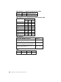
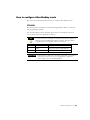
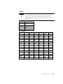
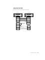
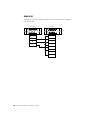
Hardware Configuration Reference Guide Doc ID 9399-HDWAREREF-JAN00 Contacting Rockwell Technical Support Telephone—440-646-5800 Software Technical Support Fax—440-646-7801 World Wide Web—www.software.rockwell.com Copyright Notice 2000 Rockwell Software Inc. All rights reserved Printed in the United States of America Portions copyrighted by Allen-Bradley Company, Inc. and used with permission. This manual and any accompanying Rockwell Software products are copyrighted by Rockwell Software Inc. Any reproduction and/or distribution without prior written consent from Rockwell Software Inc. is strictly prohibited. Please refer to the license agreement for details. Trademark Notices WINtelligent Series is a registered trademark, and the Rockwell Software logo, RSAlarm, RSAnimator, RSAssistant, RSBatch, RSBreakerBox, RSButton, RSChart, RSCompare, RSControlRoom, RSData, RSDataPlayer, RSEventMaster, RSGuage, RSJunctionBox, RSLogix Emulate 5, RSLogix Emulate 500, RSGuardian, RSHarmony, RSKeys, RSLadder, RSLadder 5, RSLadder 500, RSLinx, RSLogix 5, RSLogix 500, RSLogix Frameworks, RSMailman, RSNetworx for ControlNet, RSNetworx for DeviceNet, RSPortal, RSPower, RSPowerCFG, RSPowerRUN, RSPowerTools, RSRules, RSServer32, RSServer, RSServer OPC Toolkit, RSSidewinderX, RSSlider, RSSnapshot, RSSql, RSToolbox, RSToolPak I, RSToolPak II, RSTools, RSTrainer, RSTrend, RSTune, RSVessel, RSView32, RSView, RSVisualLogix, RSWheel, RSWire, RSWorkbench, RSWorkshop, SoftLogix 5, A.I. Series, Advanced Interface (A.I.) Series, AdvanceDDE, ControlGuardian, ControlView, INTERCHANGE, Packed DDE, WINtelligent, WINtelligent LINX, WINtelligent LOGIC 5, WINtelligent VIEW, WINtelligent RECIPE, WINtelligent VISION, and WINtelligent VISION2 are trademarks of Rockwell Software Inc. PLC, PLC-2, PLC-3 and PLC-5 are registered trademarks, and Data Highway Plus, DH+, DHII, DTL, MicroLogix, ControlLogix 5550, Network DTL, PowerText, Pyramid Integrator, PanelBuilder, PanelView, PLC-5/250, PLC-5/20E, PLC-5/40E, PLC-5/80E, SLC, SLC 5/01, SLC 5/02, SLC 5/03, SLC 5/04, SLC 5/05, and SLC 500 are trademarks of the Allen-Bradley Company, Inc. Microsoft, MS-DOS, Windows, and Visual Basic are registered trademarks, and Windows 95, Windows NT, Windows 98, Microsoft Access, Microsoft Excel are trademarks of the Microsoft Corporation. Lotus 1-2-3 is a trademark of the Lotus Corporation. ControlNet is a trademark of ControlNet International. Ethernet is a registered trademark of Digital Equipment Corporation, Intel, and Xerox Corporation. IBM is a registered trademark of International Business Machines Corporation. AIX, PowerPC, Power Series, RISC System/6000 are trademarks of International Business Machines Corporation. UNIX is a registered trademark in the United States and other countries, licensed exclusively through X/Open Company Limited. AutoCAD is a registered trademark of Autodesk, Inc. All other trademarks are the property of their respective holders and are hereby acknowledged. Warranty This Rockwell Software product is warranted in accord with the product license. The product's performance will be affected by system configuration, the application being performed, operator control and other related factors. The product's implementation may vary among users. This manual is as up-to-date as possible at the time of printing; however, the accompanying software may have changed since that time. Rockwell Software reserves the right to change any information contained in this manual or the software at anytime without prior notice. The instructions in this manual do not claim to cover all the details or variations in the equipment, procedure, or process described, nor to provide directions for meeting every possible contingency during installation, operation, or maintenance. Preface Purpose of this Document This document provides you with reference information to configure your hardware with Rockwell Software (RS) products. This document may be used as reference guide and/or troubleshooting guide. Supplemental Publications We suggest that you accompany this document with other Allen-Bradley (A-B) publications that have been published for the hardware you have purchased. See Chapter 1 for a Publication Reference chart that provides publication numbers and titles of additional documentation. In addition, we suggest that you consult the Rockwell Software documentation provided with your software. For additional reading, refer to the following A-B publications: SD499 Allen-Bradley Publications Index B112 Allen-Bradley Automation Systems ICCG-1.2 Control, Communication, and Information Reference Guide Please contact Allen-Bradley for more information. Intended Audience We assume you are familiar with: the Allen-Bradley products in your system. your IBM-compatible personal computer (PC). the MS-DOS, Windows 3.x, Windows for Workgroups 3.x, Windows 95, or Windows NT operating environments. i Document Conventions The conventions used throughout this document for the user interface comply with those recommended by Microsoft. If you are not familiar with the Microsoft Windows user interface, we recommend that you read the documentation supplied with the operating system you are using before attempting to use this software. There are also several abbreviations used in this document. A-B Allen-Bradley BNC A connector for coaxial cable. DH Data Highway IRQ Interrupt Request PC Personal Computer RS Rockwell Software SW-1 The letters SW will be accompanied by a number. This signifies a switch assembly. SW-2 Base Memory Address 1 2 Feedback Please use the feedback form packaged with your software to report errors or let us know what information you would like to see added in future editions of this document. ii Table of contents Chapter 1 Before using this document........................................................................................... 1 What operating system am I using?......................................... 2 What communication network am I using? ............................. 2 What communication card or module am I using? .................. 3 What is memory management software? ................................ 4 MS-DOS ........................................................................................................................................ 5 Windows 95................................................................................................................................... 6 386MAX......................................................................................................................................... 7 QEMM ........................................................................................................................................... 8 Publication reference............................................................... 9 Chapter 2 Hardware configuration ................................................................................................ 11 How to use this chapter......................................................... 11 Communication networks ...................................................... 12 How to configure Allen-Bradley modules............................... 13 1770-KF2 (Series B)................................................................................................................... 13 1770-KF3 ..................................................................................................................................... 17 1770-KFC .................................................................................................................................... 19 1770-KFD.................................................................................................................................... 21 1785-KE (Series B)..................................................................................................................... 23 How to configure Allen-Bradley cards ................................... 27 1784-KL ....................................................................................................................................... 27 1784-KT....................................................................................................................................... 28 iii 1784-KT2..................................................................................................................................... 30 1784-KTC/KTCX ..................................................................................................................... 31 1784-KTX/KTXD/KTS.......................................................................................................... 36 1784-PCMK ................................................................................................................................ 38 How to configure S-S Technologies cards ............................. 39 5136-SD (Revision 1)................................................................................................................. 39 5136-SD (Revision 2)................................................................................................................. 42 5136-SD-MCA ............................................................................................................................ 46 Chapter 3 Communication cables..................................................................................................47 How to use this chapter ......................................................... 47 Cables ..................................................................................... 48 9399-C5/1784-CAK .................................................................................................................. 49 9399-C6/1784-CAS ................................................................................................................... 50 9399-C7 ........................................................................................................................................ 51 9399-C8 ........................................................................................................................................ 52 9399-C9/1784-CYS ................................................................................................................... 53 9399-C10...................................................................................................................................... 54 9399-C11...................................................................................................................................... 55 9399-C13...................................................................................................................................... 56 9399-C13B ................................................................................................................................... 57 9399-C14...................................................................................................................................... 58 9399-C15/1784-CP5.................................................................................................................. 59 9399-C16...................................................................................................................................... 60 9399-C17/1772-TC.................................................................................................................... 61 9399-C18/1784-CP2.................................................................................................................. 62 9399-C19/1784-CP.................................................................................................................... 63 9399-C20...................................................................................................................................... 64 9399-C21...................................................................................................................................... 65 9399-C23/1784-CP3.................................................................................................................. 66 iv Hardware Configuration Reference Guide 9399-C25...................................................................................................................................... 67 9399-C26/1784-CP7.................................................................................................................. 68 9399-C27 (Obsolete).................................................................................................................. 69 9399-C28/1784-CP10................................................................................................................ 70 9399-C29/1747-CP3.................................................................................................................. 71 9399-C30...................................................................................................................................... 72 Index ............................................................................................................................. 73 v vi Hardware Configuration Reference Guide Chapter Before using this document To use this document effectively, please read the following sections and familiarize yourself with the terminology used throughout this document. After becoming familiar with the basic terminology, you will be ready to configure your hardware with Rockwell Software products. This chapter explains: Operating systems Communication links Communication cards and modules Memory management software At the end of the chapter, there is a Publication Reference chart that lists the publications for the communication card or modules in this document. Consult these publications for further information on your hardware. 1 What operating system am I using? There are five operating systems that are referenced in this document. MS-DOS Windows 3.x Windows for Workgroups 3.x Windows 95 Windows NT What communication network am I using? There are seven local area networks (LANs) that are used to transfer data that are referenced in this document. LAN Description Data Highway (DH) An Allen-Bradley floating-master baseband local area network. Data Highway Plus (DH+) An Allen-Bradley token-passing baseband local area network. Data Highway II (DHII) An Allen-Bradley token-passing carrier-band local area network. Data Highway 485 (DH485) An Allen-Bradley token-passing baseband link for a local area network based on the RS-485 standard. ControlNet An Allen-Bradley open control network that uses the producer/consumer model to combine the functionality of an I/O network and a peer-to-peer network. DeviceNet An open communication network designed to provide an interface through a single cable from a PLC processor directly to devices such as sensors, pushbuttons, and drives. Ethernet A local area network with a baseband communication rate of 10Mbits/second. 2 Hardware Configuration Reference Guide What communication card or module am I using? In this document, there is hardware configuration information on the following modules and cards. Modules Description 1770-KF2B Provides an interface from a RS-232C or RS-422A device to a Data Highway (DH) or a Data Highway Plus (DH+) network. 1770-KF3 Allows the host computer on an RS-232C link to communicate with SLC processors on a DH485 network. 1770-KFC Connects devices network that cannot communicate directly on the link to a ControlNet network. 1770-KFD Allows connection from an IBM-compliant laptop, desktop, or notebook computer to a DeviceNet network. 1785-KE Provides an interface between RS-232C devices to a Data Highway Plus (DH+) network. Cards Description 1784-KL Provides an interface from a PC bus to a Data Highway Plus (DH+) network. 1784-KT Provides an interface from a PC bus directly to a PLC-5, PLC-3, or PLC-2 processor, or over a Data Highway Plus (DH+) network to a PLC-5 processor. 1784-KT2 Allows an IBM/PS2 personal computer workstation to communicate directly to a PLC-5, PLC-3, or PLC-2 processor, or over a Data Highway Plus (DH+) network to any processor. 1784-KTC/ KTCX Allows a 16-bit ISA or a 32-bit EISA-compatible computer to communicate on a ControlNet network. 1784-KTX/ KTXD/KTS Allows the ISA/EISA PC bus to communicate with PLC or SLC processors via a DH, DH485, or remote I/O network. 1784-PCMK Provides a PCMCIA communication interface between an IBM compliant notebook computer and PLC and SLC processors. 5136-SD (Rev 1 and 2) Communicates from a PC bus to a Data Highway (DH) or Data Highway (DH+) network. 5136-SD-MCA Communicates to a Data Highway (DH) or a Data Highway Plus (DH+) network. (Direct-Link Interface card) Before using this document 3 What is memory management software? This discussion of memory management software and memory exclusion is directed towards the MS-DOS, Windows 3.x, Windows for Workgroups 3.x, and Windows 95 operating systems. Please be aware that you do not need this software with Windows NT. Memory management software optimizes the use of memory in your computer. If your computer has expanded memory (EMS) or extended memory (XMS) installed, you will be using memory management software. Memory management software programs supervise the use of extended memory so that applications do not try to use the same memory simultaneously. Configure the memory manager to exclude (not use) memory addresses required by your interface hardware. Determine the specific range of memory addresses used in order to prevent memory conflicts. 4 Hardware Configuration Reference Guide MS-DOS Microsoft supplies three files that manage memory usage in your computer with MS-DOS. EMM386.EXE HIMEM.SYS SMARTDRV.SYS EMM386.EXE EMM386.EXE is a type of extended memory manager program provided with MS-DOS. In the CONFIG.SYS file, the command line that loads EMM386.EXE can be modified to avoid conflicts with DH485 and DH+ compatible cards. 1. Use the exclude statement with EMM386.EXE to specify which address to avoid. The command line below avoids an A-B 1784-KT communication card with a memory address of D800. DEVICE=C:\DOS\EMM386.EXE EXCLUDE=D800-DBFF 2. Use the MEMMAKER utility to assist you in allocating memory if you are not using 386MAX or QEMM. MEMMAKER makes more conventional memory available by loading some device drivers and memory-resident programs into the upper memory area. TIP MEMMAKER can be too aggressive and cause communications problems. Apply this utility with caution. HIMEM.SYS The MS-DOS operating system includes the extended memory manager program HIMEM.SYS. HIMEM.SYS is necessary for EMM386.EXE to function. SMARTDRV.SYS The SMARTDRV.SYS is a disk-caching program designed to decrease the amount of time the operating system takes to read data from the hard drive. The SMARTDrive program needs the HIMEM.SYS extended memory manager. Consult your MS-DOS documentation for more details. Before using this document 5 Windows 95 How to exclude memory areas in the SYSTEM.INI file TIP Regardless of whether you are using memory management software (a memory manager that is loaded in CONFIG.SYS), add an exclude statement to the SYSTEM.INI file. IMPORTANT Be sure to make a backup copy of the SYSTEM.INI file before editing it. SYSTEM.INI is a Windows initialization file that contains settings that you can use to customize Windows for your system’s hardware. Using Notepad or another text editor, add a statement to your Windows SYSTEM.INI file to exclude the memory range required by your specific communication interface card. SYSTEM.INI is located in the \WINDOWS subdirectory. 1. Add the exclude statement anywhere in the [386 Enh] section. The exclude statement below avoids conflict with the 1784-KT communication interface card at an address of D800. emmexclude=D800-DBFF 2. After adding this line to the SYSTEM.INI file, exit and restart Windows. This is necessary for the changes to take effect. 6 Hardware Configuration Reference Guide 386MAX 386MAX is a type of memory management software produced by Qualitas, Inc. Use 386MAX to avoid conflicts with the following communication interface cards: Allen-Bradley 1784-KL 1784-KT 1784-KT2 1784-KTX/KTXD/KTS 1784-PCMK 1784-KTC/KTCX S-S Technologies, Inc. 5136-SD (Revisions 1 and 2) 5136-SD-MCA How to avoid conflicts with the Allen-Bradley communication interface cards 386MAX includes a program named MAXIMIZE.EXE. This program examines your computer and makes sure that there will not be any memory conflicts with your existing hardware. If you use MAXIMIZE.EXE to configure 386MAX, there should be no conflicts with A-B communication interface cards. See the 386MAX documentation for more details. How to avoid conflicts with S-S Technologies, Inc. communication interface cards The CONFIG.SYS file launches a 386MAX reference initialization file named 386MAX.PRO stored in the 386MAX subdirectory. The 386MAX.PRO file can be modified to prevent memory conflicts with S-S Technologies communication interface cards. Add a RAM=statement in the 386MAX.PRO file to specify the memory addresses to avoid. See the following example to prevent memory conflicts with a 5136-SD with a memory address of D800. RAM=D800-DBFF When making a change to your system configuration and installing 386MAX, run MAXIMIZE.EXE to optimize your memory management. Consult the 386MAX documentation for details. Before using this document 7 QEMM QEMM is a type of memory management software produced by Quarterdeck, Inc. Use QEMM to avoid conflicts with the following communication interface cards: Allen-Bradley 1784-KL 1784-KT 1784-KT2 1784-KTX/KTXD/KTS 1784-PCMK 1784-KTC/KTCX S-S Technologies, Inc. 5136-SD (Revisions 1 and 2) 5136-SD-MCA The command line in your CONFIG.SYS file that launches QEMM may be modified to prevent memory conflicts with these communication interface cards. Use the EXCLUDE qualifier in the DEVICE= statement that launches QEMM to specify which address to avoid. The following statement is designed to prevent memory conflicts with an A-B 1784-KT with a memory address of D800. DEVICE=C:\QEMM\QEMM\QEMM.SYS X=D800-DBFF When using Rockwell Software products with QEMM, disable QEMM Stealth Mode. Consult the QEMM documentation for details. Whenever you make a change to the system configuration and QEMM is installed, run QEMM’s OPTIMIZE.EXE to optimize your memory management. Consult the QEMM documentation for details. 8 Hardware Configuration Reference Guide Publication reference Allen-Bradley Publication Title Publication Numbers 1770-KF2B DH/DH+ Asynchronous RS-232 or RS-422 Interface Module User Manual 1770-6.5.13 1770-KF3 DH485 Communication Module User Manual 1770-6.5.18 1770-KFC ControlNet Communication Interface Module User Manual 1770-6.5.20 1770-KFD 1770-KFD Communication Protocol Reference Manual 1770-6.5.22 1785-KE 1785-KE Data Highway Communications Interface Module User Manual 1785-6.5.2 1784-KL Data Highway Plus Local Area Network Product Data 1785-2.6 1784-KT Communication Interface Module Installation Data 1784-2.31 1784-KT2 Communication Interface Module Installation Data 1784-6.5.16 1784-KTX/KTXD/KTS 1784 Communication Interface Card User Manual 1784-6.5.22 1784-PCMK PCMK Communication Card User Manual 1784-6.5.19 1784-KTC/KTCX ControlNet Communication Interface Card Installation Instructions 1784-5.20 5136-SD (Rev 1 and 2) 5136-SD User’s Guide SDMS.DOC 5136-SD-MCA 5136-SD-MCA Direct Link Interface User’s Guide MCMAN.DOC Modules Cards S-S Technologies Cards Before using this document 9 10 Hardware Configuration Reference Guide Chapter Hardware configuration This chapter provides basic configuration instructions for communication cards and modules manufactured by either Allen-Bradley or S-S Technologies. There is a Communication Links chart in this chapter for product comparison. If you have any additional questions on your hardware, we suggest that you contact the hardware manufacturer. If you have additional questions on configuring your hardware for Rockwell Software products, please contact Rockwell Software technical support. How to use this chapter 1. Determine the type of communication interface card or module that you are configuring. 2. Refer to the appropriate section of this chapter. If you need additional information on your hardware, refer to the documentation from the manufacturer. The Allen-Bradley and S-S Technologies publication numbers are included in each section of this chapter and in Chapter 1 of this document. TIP You may not have all the communication interface cards or modules listed in this chapter. It is only necessary that you follow the instructions for the type of communication interface card or module that will be used in your system. TIP Not all software supports all hardware. If you foresee or encounter an incompatibility problem, refer to your hardware and software documentation for the solution or contact Rockwell Software technical support. 11 Communication networks Communication Networks Product Catalog Number Data Highway (DH) Data Highway (DH+) x x Data Highway II (DHII) Data Highway 485 (DH485) ControlNet DeviceNet Modules 1770-KF2B x 1770-KF3 x 1770-KFC x Allen-Bradley 1770-KFD x 1785-KE Cards 1784-KL x 1784-KT x 1784-KT2 x 1784-KTC x 1784-KTCX x 1784-KTX 1784-KTXD x x x x x x 1784-KTS (RIO) Technologies S-S 1784-PCMK Cards 5136-SD (Rev 1) x x 5136-SD (Rev 2) x x 5136-SD-MCA x x 12 Hardware Configuration Reference Guide Ethernet How to configure Allen-Bradley modules This section provides information on how to configure Allen-Bradley modules. 1770-KF2 (Series B) This module provides an interface from an RS-232C or RS-422A device to the Data Highway or the Data Highway (DH+). On the bottom of the module, there are eight switch assemblies. Each of the switch assemblies may contain up to five switches. For more information on the 1770-KF2B, please refer to DH/DH+ Asynchronous RS-232 or RS-422 Interface Module User Manual, publication 1770-6.5.13. The 1770-KF2B reads the status of the communications option switches only at power-up. Make the selections with the power OFF. IMPORTANT Side View ON ON Front View 1 A-B OFF O N ON O F F ALLEN-BRADLEY PWR XMTG RCVG DATA-HIGHWAY COMMUNICATION INTERFACE RDY ACTV OFF CPU 2 OFF SW-1 Asynchronous Link Features SW-8 RS-232-C/RS-422-A Selection 1 1 2 2 3 4 SW-5 SW-6 Network Asynchronous Link Communication Communication Rate Rate SW-2, SW-3, SW-4 Station Address 5 1 1 2 2 3 1 2 3 1 1 2 2 3 SW-7 Communication Link Selection 4 1 O N O N O N O N O N O N O N O N O F F O F F O F F O F F O F F O F F O F F O F F 2 Hardware configuration 13 SW-1 (Asynchronous Link Features) Protocol Error Parity checking Embedded Switch Response 1 2 3 4 5 Full duplex BCC None No OFF OFF n/a n/a OFF Full duplex BCC Even No ON OFF OFF Full duplex BCC None Yes OFF ON OFF Full duplex BCC Even Yes ON ON OFF Half duplex BCC None No OFF OFF ON Half duplex BCC Even No ON OFF ON Full duplex CRC None Yes OFF ON ON Half duplex CRC None No ON ON ON SW-1 Switch 3 (Duplicates) Messages Switch 3 Detect and ignore duplicates ON Accept all regardless of duplication OFF SW-1 Switch 4 (Handshaking) Handshaking Switch 4 Use handshaking signals ON Ignore handshaking signals OFF 14 Hardware Configuration Reference Guide SW-2 (Station Address) First Digit SW-3, SW-4 (Station Address) Second and Third Digits Digit Switch 1 Switch 2 Digit Switch 1 Switch 2 Switch 3 0 OFF OFF 0 OFF OFF OFF 1 OFF ON 1 OFF OFF ON 2 ON OFF 2 OFF ON OFF 3 ON ON 3 OFF ON ON 4 ON OFF OFF 5 ON OFF ON 6 ON ON OFF 7 ON ON ON SW-5 (Network Communication Rate) Switch 1 Switch 2 Communication rate ON ON 57,600 bits per second SW-6 (Asynchronous Link Communication Rate) Bits per second Switch 1 Switch 2 Switch 3 110 OFF OFF OFF 300 ON OFF OFF 600 OFF ON OFF 1200 ON ON OFF 2400 OFF OFF ON 4800 ON OFF ON 9600 OFF ON ON SW-6 Switch 4 (Diagnostic Command) Status Switch 4 Execute ON Pass OFF Hardware configuration 15 SW-7 (Communication Link Selection) Network Switch 1 Switch 2 Data Highway (DH) OFF OFF Data Highway Plus (DH+) or Peer Communication Link (PCL) ON OFF Communication interface Switch 1 Switch 2 RS-232C OFF ON RS-422A ON OFF SW-8 (RS-232C/RS-422A) 16 Hardware Configuration Reference Guide 1770-KF3 This module is an interface between a host computer on an RS-232C link and SLC processors on a Data Highway 485 (DH485) network. On the bottom of the module, there is a pushbutton display that is used to configure the module’s communication parameters. For more information on the 1770-KF3, please refer to DH485 Communication Module User Manual, publication 1770-6.5.18. A-B ALLEN-BRADLEY DH 485 COMMUNICATION INTERFACE RS 232 DH 485 ACTIVITY ACTIVITY FAULT POWER Current Setting Communication Parameter Save View Data Exit Hardware configuration 17 Communication Parameters (Factory Defaults) DH485 Parameters Parameter Number Parameter Factory Default 0 DH485 Node Address 00 1 DH485 Baud Rate 96 (9600 baud) 2 Diagnostic Command Execution 01 (the KF3 executes the commands) 3 RS-232C Baud Rate 96 (9600 baud) 4 RS-232C Parity 00 (none) 5 DF1 Device Category 00 (full duplex) RS-232C Parameters Parameter Number Parameter Factory Default 6 Error Detection 00 (BCC) 7 Flow Control 00 (Disabled) 8 Duplicate Message Detection 01 (Enabled) 9 Sub-menu Parameters N/A A Series and Revision N/A Advanced Communication Parameters Parameter Number Parameter Factory Default 0 Maximum Token Holder 31 1 Token Hold Factor 01 2 Number of Retries 02 3 DF1 ACK Timeout 10 (1.0 second timeout) 4 CTS to Transmit Delay 00 (no delay) 5 End of Message to RTS Off 00 (no delay) 6 Master Station Address 10 (octal) 7 Group Number 00 18 Hardware Configuration Reference Guide 1770-KFC This module provides an interface from RS-232C devices to the ControlNet network. On the bottom of the module, there is a push button display that is used to configure the communication parameters. For more information on the 1770-KFC, please refer to ControlNet Communication Interface Module User Manual, publication 1770-6.5.20. Status LEDs Fuse Parallel Port Reset Switch RS-232C Port Network Access Port ControlNet Port A BNC Connector Power Connector ControlNet Port B BNC Connector Current Setting Communication Parameter Save View Data Exit Hardware configuration 19 Communication Parameters (Factory Defaults) Basic Communication Parameters Parameter Number Parameter Factory Default 0 Network address 02 1 DF1 port 00 2 Baud Rate 96 3 Parity 00 4 Full/Half Duplex 00 5 Parallel Port Transfer 01 6 Error detection 00 7 DF1 Station address 00 8 Diagnostic Command Execution 00 A Sub-menu N/A F Series/Revision N/A Advanced Communication Parameters Parameter Number Parameter Factory Default 0 Number of Retries 02 1 Duplicate message detection 01 2 DF1 ACK Time-out 10 3 Modem Handshaking 00 4 CTS to transmit delay No delay (00) 5 End of message to RTS off No delay (00) 20 Hardware Configuration Reference Guide 1770-KFD This module provides an interface from RS-232 devices to the DeviceNet network. This module is configured through your software. For more information on the 1770-KFD, please refer to 1770-KFD Communication Protocol Reference Manual, publication 1770-6.5.22. NETWORK STATUS MODULE STATUS INTERFACE RS-232 RS-232 STATUS A-B ALLEN-BRADLEY Network Status Indicator Color Status Off Offline Flashing green Online Solid red Link failed (critical fault) Solid green Online, communicating Hardware configuration 21 Module Status Indicator Color Status Off No power Solid green Device OK Flashing green Not configured Solid red Critical fault Flashing red Non-critical fault RS-232 Indicator Color Status Off No activity, link OK Flickering green Activity, link OK Solid red Link failed (critical fault) Flashing red Link failed (non-critical fault) 22 Hardware Configuration Reference Guide 1785-KE (Series B) This module provides an interface between RS-232C devices to a Data Highway Plus (DH+) network. On the side of the module, there are four switch assemblies. Each of the switch assemblies may contain up to eight switches. There is also a switch guide printed on the side of the module. For more information on the 1785-KE, please refer to 1785-KE Data Highway Communications Interface Module User Manual, publication 1785-6.5.2. SW-2 Station Address SW-1 Asynchronous Link Features O F F 1 2 3 4 5 6 O F F 1 2 3 O N O N ON 4 5 6 7 8 SW-3 Communication Rate O F F O N 1 2 3 4 5 6 SW-4 O F F 1 2 3 4 O N OFF Hardware configuration 23 SW-1 (Asynchronous Link Features) Protocol Error Parity Checking Embedded Switch Response 1 2 3 Full duplex BCC None No OFF OFF OFF Full duplex BCC Even No ON OFF OFF Full duplex BCC None Yes OFF ON OFF Full duplex BCC Even Yes ON ON OFF Full duplex BCC None No OFF OFF ON Half duplex BCC Even No OFF ON ON Full duplex CRC None Yes OFF ON ON Half duplex CRC None No ON ON ON SW-1 Switch 4 (Duplicate) Messages Switch 4 Detect and ignore duplicates ON Accept all regardless of duplication OFF SW-1 Switch 5 (Handshaking) Handshaking Switch 5 Use handshaking signals ON Ignore handshaking signals OFF SW-1 Switch 6 (Diagnostics) Diagnostic Command Switch 6 Execute ON Pass OFF 24 Hardware Configuration Reference Guide SW-2 Switches 1, 2 (Station Address) Switch 1 Switch 2 ON ON SW-2 Switches 3, 4, 5 (Octal Digit 1)(most significant) To set first digit (octal): Switch 3 4 5 0 ON ON ON 1 ON ON OFF 2 ON OFF ON 3 ON OFF OFF 4 OFF ON ON 5 OFF ON OFF 6 OFF OFF ON 7 OFF OFF OFF SW-2 Switches 6, 7, 8 (Octal Digit 2)(least significant) To set second digit (octal): Switch 6 7 8 0 ON ON ON 1 ON ON OFF 2 ON OFF ON 3 ON OFF OFF 4 OFF ON ON 5 OFF ON OFF 6 OFF OFF ON 7 OFF OFF OFF Hardware configuration 25 SW-3 Switches 1, 2 (Network Communication Rate) Switch 1 Switch 2 Communication rate ON ON 57, 600 bits per second SW-3 Switches 3, 4, 5 (Asynchronous Communication Rate) Bits per second Switch 3 4 5 110 OFF OFF OFF 300 ON OFF OFF 600 OFF ON OFF 1200 ON ON OFF 2400 OFF OFF ON 4800 ON OFF ON 9600 OFF ON ON 19200 ON ON ON SW-3 Switch 6 To use the 1785-KE to connect Switch 6 Computer or other intelligent RS-232C device Local (ON) to a Data Highway Plus network Data Highway Plus node (such as a PLC-5) as Remote (OFF) a slave on a multidrop link, using a modem Two Data Highway Plus networks over a point-to-point modem link SW-4 Switch 1 Switch 2 Switch 3 Switch 4 OFF OFF OFF OFF 26 Hardware Configuration Reference Guide Remote (OFF) How to configure Allen-Bradley cards This section provides information on how to configure Allen-Bradley cards. 1784-KL This card provides an interface from the Data Highway Plus (DH+) to the A-B T47 programming terminal. For more information on the 1784-KL, please refer to Data Highway Plus Local Area Network Product Data, publication 1785-2.6. TIP It is not necessary to configure the 1784-KL card’s memory address or interrupt for use with Rockwell Software products. The base address and interrupt are not adjustable and are set as follows: Series Base Address IRQ A E000 None (the card uses Polled Mode) B E000 2 IMPORTANT Exclude memory addresses from E000 to E100 with your memory management software. If you are using Windows, exclude the memory addresses in the SYSTEM.INI file. Hardware configuration 27 1784-KT This card provides an interface from a PC bus to a Data Highway Plus (DH+) network. The 1784-KT card contains a set of DIP switches and a jumper which must be set before you can use the 1784-KT with your Rockwell Software product. For more information on the 1784-KT card, please refer to Communication Interface Module Installation Data, publication 1784-2.31. Base Address 3 4 5 6 3 2 7 5 4 1 Interrupt Factory base address setting of D400 ON OFF IMPORTANT Be careful when reading the switches on the 1784-KT card. The side of the switch that is pushed into the switch block is the activated side. (The small red dots on the switches do not denote the switch’s position.) 28 Hardware Configuration Reference Guide Interrupt TIP WINtelligent LINX does not use the 1784-KT interrupt. However, you may be using other software that does use the 1784-KT interrupt. In that case, set the interrupt as recommended for that software. The 1784-KT interrupt may conflict with other devices in your computer as shown below. Interrupt May conflict with 3 COM2 4 COM1 5 LPT2 7 LPT1 Base Address Address Switch 1 Switch 2 Switch 3 Switch 4 Switch 5 Switch 6 A000 ON ON ON OFF ON OFF A400 OFF ON ON OFF ON OFF A800 ON OFF ON OFF ON OFF AC00 OFF OFF ON OFF ON OFF B000 ON ON OFF OFF ON OFF B400 OFF ON OFF OFF ON ON B800 ON OFF OFF OFF ON OFF C000 ON ON ON ON OFF OFF C400 OFF ON ON ON OFF OFF C800 ON OFF ON ON OFF OFF CC00 OFF OFF ON ON OFF OFF D000 ON ON OFF ON OFF OFF D400 OFF ON OFF ON OFF OFF D800 ON OFF OFF ON OFF OFF Hardware configuration 29 1784-KT2 This module is an IBM/PS2 MicroChannel card that provides an interface from a PC bus to a Data Highway Plus (DH+) network. Use an IBM Reference Diskette to configure this module. For more information on the 1770-KT2, please refer to Communication Interface Module Data, publication 1784.6.5.16. TIP Please refer to your Allen-Bradley documentation for installing and configuring this module. Supported memory addresses C000-C3FF C400-C7FF C800-CBFF CC00-CFFF D000-D3FF D400-D7FF D800-DBFF DC00-DFFF Supported interrupts IRQ9 IRQ10 IRQ11 IRQ12 30 Hardware Configuration Reference Guide 1784-KTC/KTCX This card provides an interface from a PC bus to the ControlNet network. The 1784-KTCX is the card pictured in this documentation. There are two series to this card: A and B. The 1784-KTCX series A/B contains two BNC receptacles to connect directly to a ControlNet network. The 1784-KTC series A/B is identical to the KTCX series A/B except that the KTC does not have BNC connectors. For more information on the 1784-KTC/KTCX, please refer to ControlNet Communication Interface Card Installation Instructions, publication 1784-5.20. Series A 1784-KTC/KTCX E3 JPR1 JPR2 BNC receptacles on 1784-KTCX card only JPR3 Hardware configuration 31 Series B 1784-KTC/KTCX E1 E2 BNC receptacles on 1784-KTCX card only E3 Switch Assemblies (Series A KTC/KTCX and Series B KTC/KTCX) SW-3 Base I/O Channel Address 1 2 Side View 3 SW-2 SW-1 Base Memory Address Base Memory Address 4 1 Front View Down (0) Up (1) 32 Hardware Configuration Reference Guide 2 1 2 3 4 Base Memory Address for the Series A card IMPORTANT Do not mix 8-bit and 16-bit cards within a 64K segment boundary. A 1784-KT (series B) card cannot be placed in the same segment range of D000-DFFF or C000-CFFF. The 8-bit card may not work in this setup. The two cards, 1784-KTC (series A) (16-bit) and 1784KT (series B) (8-bit), can be placed with one in the C000-CFFF range and one in the D000-DFFF range. SW-1 SW-2 Base Memory Address Base Memory Address SW-2 SW-1 Switch Switch 1 2 1 2 3 4 C000 DOWN DOWN DOWN DOWN UP UP C400 UP DOWN DOWN DOWN UP UP C800 DOWN UP DOWN DOWN UP UP CC00 UP UP DOWN DOWN UP UP D000 DOWN DOWN UP DOWN UP UP D400 UP DOWN UP DOWN UP UP D800 DOWN UP UP DOWN UP UP DC00 UP UP UP DOWN UP UP Hardware configuration 33 SW-3 Base I/O Channel Address Base I/O Channel Address Switch 1 2 3 4 200 DOWN DOWN DOWN DOWN 220 UP DOWN DOWN DOWN 240 DOWN UP DOWN DOWN 260 UP UP DOWN DOWN 280 DOWN DOWN UP DOWN 2A0 UP DOWN UP DOWN 2C0 DOWN UP UP DOWN 2E0 UP UP UP DOWN 300 DOWN DOWN DOWN UP 320 UP DOWN DOWN UP 340 DOWN UP DOWN UP 360 UP UP DOWN UP 380 DOWN DOWN UP UP 3A0 UP DOWN UP UP 3C0 DOWN UP UP UP 3E0 UP UP UP UP 34 Hardware Configuration Reference Guide Series A Jumper Explanations JPR 1 JPR 2 JPR 1 JPR 2 Use these jumper positions for normal card operation and field flash upgrade of card's main code. JPR 3 When installed, use this jumper to latch certain address lines that some 286 machines and older may not latch. E3 Use these jumper positions for field flash upgrade of card's boot code. This jumper must be installed during field flash upgrades. This jumper must be uninstalled during normal card operation. Series B Jumper Explanations E1 E2 Use these jumper positions for normal card operation and field flash upgrade of card's main code. E1 E2 Use these jumper positions for field flash upgrade of card's boot code. E3 When installed, use this jumper to latch certain address lines that some 286 machines and older may not latch. Hardware configuration 35 1784-KTX/KTXD/KTS Use this document to configure the 1784-KTX, the 1784 KTXD, and the 1784KTS cards. For more information on these cards, please refer to 1784 Communication Interface Card User Manual, publication 1784-6.5.22. Features Supported Product Catalog Number Channels Communicates from a PC bus to these networks Description 1784-KTX 1 DH+ or DH485 1 set of rotary dials and interrupt jumpers. RJ connector in place of middle 3pin Phoenix connector. 1784-KTXD 2 DH+ and/or DH485 2 sets of rotary dials and interrupt jumpers. 1784-KTS 1 N/A A single channel device that acts only as remote scanner. 1784-KTXD Channel 2 SW-1 SW-2 Phoenix connectors Interrupts Ch2 Ch1 TIP Channel 1 SW-3 SW-4 The 1784-KTX is similar in appearance but only has one channel and one RJ connector. 36 Hardware Configuration Reference Guide Memory Address Channel 2 SW-1 SW-3 SW-2 Channel 1 SW-4 Interrupts IRQ No IRQ Ch2 Ch1 IRQ 3 3 4 4 5 5 7 7 9 9 10 10 11 11 12 12 15 15 IRQ 5 Hardware configuration 37 1784-PCMK This card provides a PCMCIA (Personal Computer Memory Card International Association) communication interface to Data Highway Plus (DH+) and Data Highway 485 (DH485) networks, and the communication port on the front of PLC-2 processors. There are no explicit configuration instructions for this card, as Windows can handle any configuration required. For more information on the 1784-PCMK, please refer to PCMK Communication Card User Manual, publication 1784-6.5.19. IMPORTANT Your computer must be PCMCIA 2.1 compliant to support the PCMK card. EMM386.EXE Loading EMM386.EXE in the CONFIG.SYS file may interfere with the driver’s ability to map the 1784-PCMK into MS-DOS memory. Either remove EMM386.EXE from CONFIG.SYS, or use it with the WIN= option in the command line. Refer to the What is Memory Management Software section in Chapter 1 for more information on EMM386.EXE. 38 Hardware Configuration Reference Guide How to configure S-S Technologies cards This section provides information on how to configure S-S Technologies cards. 5136-SD (Revision 1) This card provides an interface from a PC bus to a Data Highway (DH) and Data Highway Plus (DH+) network. There are two revisions to this card. Revision 1 has eight switches. Revision 2 has six switches. For more information on the 5136-SD (Revision 1 and 2), please refer to 5136-SD User’s Guide, publication SDMS.DOC. Transmit Enable/Disable Jumper Enable Factory default IRQ setting of 5 and I/O Channel Address of 250 Switches ON 1 2 3 4 5 6 7 8 OFF Hardware configuration 39 I/O Channel Address I/O Channel Address Switch Remarks 4 5 6 7 8 200 ON ON ON ON ON 208 ON ON ON ON OFF 210 ON ON ON OFF ON 218 ON ON ON OFF OFF 220 ON ON OFF ON ON 228 ON ON OFF ON OFF 230 ON ON OFF OFF ON 238 ON ON OFF OFF OFF 240 ON OFF ON ON ON 248 ON OFF ON ON OFF 250 ON OFF ON OFF ON 258 ON OFF ON OFF OFF 260 ON OFF OFF ON ON 268 ON OFF OFF ON OFF 270 ON OFF OFF OFF ON 278 ON OFF OFF OFF OFF 280 OFF ON ON ON ON 288 OFF ON ON ON OFF 290 OFF ON ON OFF ON 298 OFF ON ON OFF OFF 2A0 OFF ON OFF ON ON 2A8 OFF ON OFF ON OFF 2B0 OFF ON OFF OFF ON 2B8 OFF ON OFF OFF OFF 2C0 OFF OFF ON ON ON 2C8 OFF OFF ON ON OFF 2D0 OFF OFF ON OFF ON 2D8 OFF OFF ON OFF OFF 2E0 OFF OFF OFF ON ON 40 Hardware Configuration Reference Guide Game port Default LPT2 I/O Channel Address Switch Remarks 4 5 6 7 8 2E8 OFF OFF OFF ON OFF 2F0 OFF OFF OFF OFF ON 2F8 OFF OFF OFF OFF OFF COM4 COM2 IRQ Setting IRQ Switch 1 Switch 2 Switch 3 May conflict with 3 ON OFF OFF COM2 5 OFF ON OFF LPT2 7 OFF OFF ON LPT1 None OFF OFF OFF Default Transmit Enable/Disable Jumper (JB1) Disable Enable Hardware configuration 41 5136-SD (Revision 2) This card provides an interface from a PC bus to a Data Highway (DH) and Data Highway Plus (DH+) network. There are two revisions to this card. Revision 2 has six switches. Revision 1 has eight switches. For more information on the 5136-SD (Revision 1 and 2), please refer to 5136-SD User’s Guide, publication SDMS.DOC. Transmit Enable/Disable Jumper Enable Factory default I/O Channel Address of 250 Switches ON 1 2 3 42 Hardware Configuration Reference Guide 4 5 6 OFF I/O Channel Address I/O Channel Address Switch Remarks 1 2 3 4 5 6 200 ON ON ON ON ON ON 208 ON ON ON ON ON OFF 210 ON ON ON ON OFF ON 218 ON ON ON ON OFF OFF 220 ON ON ON OFF ON ON 228 ON ON ON OFF ON OFF 230 ON ON ON OFF OFF ON 238 ON ON ON OFF OFF OFF 240 ON ON OFF ON ON ON 248 ON ON OFF ON ON OFF 250 ON ON OFF ON OFF ON 258 ON ON OFF ON OFF OFF 260 ON ON OFF OFF ON ON 268 ON ON OFF OFF ON OFF 270 ON ON OFF OFF OFF ON 278 ON ON OFF OFF OFF OFF 280 ON OFF ON ON ON ON 288 ON OFF ON ON ON OFF 290 ON OFF ON ON OFF ON 298 ON OFF ON ON OFF OFF 2A0 ON OFF ON OFF ON ON 2A8 ON OFF ON OFF ON OFF 2B0 ON OFF ON OFF OFF ON 2B8 ON OFF ON OFF OFF OFF 2C0 ON OFF OFF ON ON ON 2C8 ON OFF OFF ON ON OFF 2D0 ON OFF OFF ON OFF ON 2D8 ON OFF OFF ON OFF OFF 2E0 ON OFF OFF OFF ON ON 2E8 ON OFF OFF OFF ON OFF Game port Default LPT2 COM4 Hardware configuration 43 I/O Channel Address Switch Remarks 1 2 3 4 5 6 2F0 ON OFF OFF OFF OFF ON 2F8 ON OFF OFF OFF OFF OFF COM2 600 OFF ON ON ON ON ON Game port 608 OFF ON ON ON ON OFF 610 OFF ON ON ON OFF ON 618 OFF ON ON ON OFF OFF 620 OFF ON ON OFF ON ON 628 OFF ON ON OFF ON OFF 630 OFF ON ON OFF OFF ON 638 OFF ON ON OFF OFF OFF 640 OFF ON OFF ON ON ON 648 OFF ON OFF ON ON OFF 650 OFF ON OFF ON OFF ON 658 OFF ON OFF ON OFF OFF 660 OFF ON OFF OFF ON ON 668 OFF ON OFF OFF ON OFF 670 OFF ON OFF OFF OFF ON 678 OFF ON OFF OFF OFF OFF 680 OFF OFF ON ON ON ON 688 OFF OFF ON ON ON OFF 690 OFF OFF ON ON OFF ON 698 OFF OFF ON ON OFF OFF 6A0 OFF OFF ON OFF ON ON 6A8 OFF OFF ON OFF ON OFF 6B0 OFF OFF ON OFF OFF ON 6B8 OFF OFF ON OFF OFF OFF 6C0 OFF OFF OFF ON ON ON 6C8 OFF OFF OFF ON ON OFF 6D0 OFF OFF OFF ON OFF ON 6D8 OFF OFF OFF ON OFF OFF 44 Hardware Configuration Reference Guide LPT2 I/O Channel Address Switch Remarks 1 2 3 4 5 6 6E0 OFF OFF OFF OFF ON ON 6E8 OFF OFF OFF OFF ON OFF 6F0 OFF OFF OFF OFF OFF ON 6F8 OFF OFF OFF OFF OFF OFF COM4 COM2 Transmit Enable/Disable Jumper (JB2) Disable Enable Hardware configuration 45 5136-SD-MCA This card provides an interface from an IBM PS/2 bus to a Data Highway (DH) and Data Highway Plus (DH+) network. TIP The original cards were labeled 5136-SD-MCA. Revised cards are labeled 5136-SD2-MC (Revision 1). See S-S Technologies’ documentation for details. TIP Installing and configuring the 5136-SD-MCA requires a reference disk that is supplied with the computer. The .ADF files for installing the 5136-SD-MCA are included on the reference disk. For more information on the 5136-SD-MCA, please refer to 5136-SD-MCA Direct-Link Interface Card User’s Guide, publication MCMAN.DOC. Enable Transmit Enable/Disable Jumper Jumper Settings Card Jumper Setting Function Original card J2 Enable Enables transmission Revised card P6 Enable (left position) Enables transmission 46 Hardware Configuration Reference Guide Chapter Communication cables This chapter provides you with basic connection information. In this chapter, there is also a chart to reference the communication cables. If you have additional questions on your cabling, we suggest that you contact the cable manufacturer. If you have additional questions on cabling your hardware with Rockwell Software products, please contact Rockwell Software technical support. TIP Some of the products listed in this may be no longer available from Rockwell Software, Inc. Please contact Rockwell Software for details on availability. How to use this chapter 1. Determine the type of communication devices that you are configuring. 2. Refer to the appropriate section of Chapter 3. 47 Cables Rockwell Software Part Number Product Description Allen-Bradley Part Number 9399-C5 Serial Port to 1771-KG, -KE, -KF, or 1785-KE Module 1784-CAK 9399-C6 Serial Port to 1770-SA or 1770-SB Recorder 1784-CAS 9399-C7 Serial Port to 1770 T3 Terminal 9399-C8 6120 Industrial XT to 1771-KF, -KG, or 1785-KE Module 9399-C9 6120 Industrial XT to 1770-SA or 1770-SB Recorder 9399-C10 6120 Industrial XT to 1770 T3 Terminal 9399-C11 Serial Port to 1770-KF2B or 1770-KF3 Module 9399-C13 25-Pin Male to 9-Pin Female Adapter 9399-C13B 9-Pin Male to 25-Pin Female Adapter 9399-C14 Serial Port to1771-DB Module 9399-C15 1784-KTK1 or 1770-KF2B to PLC-5 Processor 9399-C16 Serial Port to PLC-3 Channel 0 or 5 9399-C17 Rockwell Software L2-101 Interface Card (9399-L2101) to PLC-2 Front Port 1772-TC 9399-C18 1784-KT or 1784-KL to PLC-2 Front Port 1784-CP2 9399-C19 1784-KT or 1784-KL to PLC-5 Processor 1784-CP 9399-C20 1785-KE to PLC-5 Processor (blue hose for DH, DH+, and remote I/O) 9399-C21 Serial Port to 1774-TC Cable 9399-C23 1784-KT to PLC-3 Front Port 9399-C25 Serial Port Adapter for 1774-TD Cable 9399-C26 8-Pin Mini DIN to 9-Pin Female 9399-C27 (Obsolete) 9399-C28 Serial Port to PLC-5 Channel 0 1784-CP10 9399-C29 Serial Port to SLC 500/03 Channel 0 1747-CP3 9399-C30 Serial Port to CVIM/CVIM2 RJ-45 8-Pin Connector KTC/KTCX 48 Hardware Configuration Reference Guide 1784-CYS 1784-CP5 1784-CP3 1784-CP7 1786-CP 9399-C5/1784-CAK This cable connects a T50, 6121, or IBM AT to a 1771-KG, -KE, -KF, or 1785KE module. 15-Pin Male 22 1 9 10 3 11 4 12 5 13 9-Pin Female 6 14 7 15 8 9 2 3 4 5 8 7 1 6 1 4 1 2 7 3 13 4 6 2 5 3 7 8 5 6 8 11 Communication cables 49 9399-C6/1784-CAS This cable connects a T50, 6121, or IBM AT to a 1770-SA or 1770-SB recorder. 25-Pin Male 1 14 2 15 3 16 4 17 5 18 6 19 7 9-Pin Female 8 20 9 21 22 10 23 11 24 12 13 9 1 2 3 3 2 4 7 5 8 6 6 7 5 8 1 20 4 50 Hardware Configuration Reference Guide 2 3 4 5 25 8 7 1 6 9399-C7 This cable connects an IBM AT to the 1770 T3 terminal. 9-Pin Female 9 2 3 4 5 8 7 25-Pin Male 1 6 1 14 2 15 3 16 4 17 5 18 6 7 19 3 2 2 3 7 4 8 5 6 6 5 7 1 8 4 20 20 8 9 21 22 10 23 11 24 12 13 25 Communication cables 51 9399-C8 This cable connects the 6120 Industrial XT to a 1771-KF, -KG, or 1785-KE module. 9-Pin Female 2 1 6 3 7 4 8 15-Pin Male 22 1 5 9 9 7 1 10 3 4 11 1 shield frame ground 2 3 3 2 4 4 5 5 6 11 8 6 9 8 7 13 52 Hardware Configuration Reference Guide 12 5 13 6 14 7 15 8 9399-C9/1784-CYS This cable connects the 6120 Industrial XT to 1770-SA or 1770-SB recorder. 25-Pin Male 1 14 2 15 3 16 4 17 5 18 6 19 7 20 8 9-Pin Female 9 10 21 22 23 11 24 12 25 13 9 2 3 4 5 8 7 1 6 1 2 2 3 3 4 4 5 5 6 6 7 7 8 8 20 9 Communication cables 53 9399-C10 This cable connects a 6120 Industrial XT to a 1770 T3 terminal. 9-Pin Female 9 2 3 4 5 8 7 1 25-Pin Male 1 1 14 6 2 15 3 16 Frame Ground 2 2 3 3 4 4 5 5 6 6 7 7 8 8 9 20 54 Hardware Configuration Reference Guide 4 17 5 18 6 19 7 20 8 9 21 22 10 23 11 24 12 25 13 9399-C11 This cable connects a 1770-KF2B or 1770-KF3 module. 9-Pin Female 4 5 9 3 8 2 7 25-Pin Female 13 1 25 6 Frame Ground 12 24 11 10 23 22 9 21 8 20 7 19 6 5 18 17 4 16 3 15 2 1 14 1 3 3 2 2 7 4 8 5 6 20 4 8 1 6 5 7 Communication cables 55 9399-C13 This cable is a 25-pin male to 9-pin female adapter. 25-Pin Male 1 14 2 15 3 16 4 17 5 18 6 19 7 20 9-Pin Female 8 9 21 22 10 11 23 56 Hardware Configuration Reference Guide 24 12 25 13 3 4 5 9 8 2 7 2 3 3 2 4 7 5 8 6 6 7 5 8 1 20 4 22 9 1 6 9399-C13B This cable connects to a 9-pin male to a 25-pin female port or vice versa. This cable allows a cable to be used interchangeably on 9- and 25-pin serial ports. 9-Pin Male 3 2 1 6 7 4 8 25-Pin Female 5 9 13 25 12 24 11 23 10 22 3 2 2 3 7 4 8 5 6 6 5 7 1 8 4 20 9 22 9 21 8 20 7 19 6 5 18 17 4 16 3 15 2 1 14 Communication cables 57 9399-C14 This cable connects the 9-pin serial port to the 25-pin port on the 1771-DB module. This cable comes with an adapter for use with 9- or 25-pin serial ports on the computer. 9-Pin Female 3 4 5 9 2 7 8 1 6 1 25-Pin Male 1 14 2 15 3 16 4 17 5 18 6 19 Frame Ground 3 3 2 2 5 7 6 1 4 58 Hardware Configuration Reference Guide 7 20 8 9 21 22 10 23 11 24 12 25 13 9399-C15/1784-CP5 This cable connects the 1784-KTK1 or 1770-KF2B module to a 9-pin serial port on a PC. 9-Pin Male 3 2 1 6 7 4 8 15-Pin Female 5 9 8 15 7 14 6 13 5 4 12 11 3 10 2 1 9 6 1 7 8 5 7 Communication cables 59 9399-C16 This cable is a serial port that connects the computer’s 25-pin serial port to the Channel 0 or Channel 5 on the PLC-3. This cable comes with an adapter for use with 9- or 25-pin serial ports on the computer. 25-Pin Female 13 25 12 24 11 23 10 22 9 21 8 20 7 19 25-Pin Male 6 5 18 17 4 16 3 15 2 1 1 14 14 Frame Ground 2 15 3 16 4 17 5 18 1 2 2 3 3 4 4 5 5 6 6 7 7 8 8 20 20 60 Hardware Configuration Reference Guide 6 19 7 20 8 9 21 22 10 23 11 24 12 25 13 9399-C17/1772-TC This cable connects the port on the interface card to the communication port on the front of the PLC-2 processor. 15-Pin Male 22 1 9 10 3 11 4 12 5 15-Pin Male 6 13 14 7 15 8 22 1 9 10 3 4 11 12 1 1 2 2 3 3 4 4 5 5 6 6 7 7 8 8 5 13 6 14 7 8 15 9 Communication cables 61 9399-C18/1784-CP2 This cable connects the 1784-KT or 1784-KL to the communication port on the front of the PLC-2 processor. 62-Pin Male 1 2 22 23 43 44 3 24 45 4 5 25 26 46 47 6 27 48 7 28 8 9 29 30 49 50 51 10 31 52 11 32 53 12 13 33 34 14 54 55 16 17 15 35 37 38 36 56 18 39 58 59 57 19 40 60 21 20 41 61 42 62 15-Pin Male 22 1 9 10 3 11 4 5 12 4 1 5 2 7 3 6 4 26 5 27 6 47 7 48 8 62 Hardware Configuration Reference Guide 13 6 14 7 15 8 9399-C19/1784-CP This cable connects the 1784-KT or 1784-KL to Channel 1 on a PLC-5 processor serial port. 62-Pin Male 1 22 43 2 23 44 3 24 45 4 5 25 26 46 47 6 27 48 7 8 9 29 30 28 49 50 51 10 31 52 11 32 53 12 13 33 34 54 55 14 35 56 15 36 57 16 17 37 38 58 59 18 39 19 40 60 61 20 41 21 42 62 9-Pin Male 6 36 clear clear black black 3 2 1 7 4 8 5 9 1 35 34 5 7 Communication cables 63 9399-C20 This cable connects the 1785-KE to the PLC-5 processor serial port. 9-Pin Male 3 2 1 6 7 4 8 9-Pin Male 5 9 3 2 1 6 7 1 1 7 7 5 5 64 Hardware Configuration Reference Guide 4 8 5 9 9399-C21 This cable connects a 9-pin serial port to the 1774-TC cable. This cable comes with an adapter for use with 9- or 25-pin serial ports on the computer. 9-Pin Female 3 4 5 9 8 2 7 25-Pin Female 1 6 13 25 12 24 11 23 10 22 9 21 2 3 3 2 5 18 8 20 7 19 6 5 18 17 4 16 3 15 2 1 14 25 Communication cables 65 9399-C23/1784-CP3 This cable connects the 1784-KT to the PLC-3 processor serial port. 62-Pin Male 1 22 43 2 23 44 3 24 4 5 25 26 46 47 45 6 27 48 7 28 49 8 9 29 30 50 51 10 31 52 11 32 53 12 13 33 34 54 55 14 16 17 15 35 37 38 36 56 18 58 59 57 19 39 60 21 20 40 41 61 42 62 25-Pin Male 1 14 2 15 3 16 4 17 5 6 18 23 3 24 18 2 25 1 14 1 66 Hardware Configuration Reference Guide 19 7 20 8 9 21 22 10 23 11 24 12 25 13 9399-C25 This cable connects the computer’s 9-pin serial port to the 1774-TD cable. 25-Pin Female 13 25 12 24 11 23 10 22 9 21 8 20 7 19 6 9-Pin Female 5 4 18 17 16 3 15 2 14 1 3 4 5 9 2 7 8 2 2 3 3 7 5 5 1 4 4 6 6 8 8 1 6 7 Communication cables 67 9399-C26/1784-CP7 This cable connects an 8-pin Mini DIN to a 9-pin female. 8-Pin Mini-DIN connector 9-Pin Female 3 4 5 9 2 7 8 1 1 6 3 6 7 5 1 68 Hardware Configuration Reference Guide Shield Blue Clear 3 1 6 9399-C27 (Obsolete) The 9399-C27 cable is an obsolete gender changer. It was used in conjunction with the RS 9399-C11 cable to connect the computer serial port to Channel 0 of an Enhanced PLC-5 processor. The combined cable function is now accomplished with the RS 9399-C28 cable. 25-Pin Male 1 14 2 15 3 16 4 17 5 18 6 19 7 20 25-Pin Male 8 9 21 22 10 11 23 24 12 25 13 1 2 14 1 1 2 2 3 3 4 4 5 5 6 6 7 7 8 8 9 9 10 10 11 11 12 12 13 13 14 14 15 15 16 16 17 17 18 18 20 20 21 21 22 22 23 23 24 24 25 25 15 3 16 4 17 5 18 6 7 19 20 8 21 9 22 10 23 11 24 12 13 25 Communication cables 69 9399-C28/1784-CP10 This cable connects the to Channel 0 of an Enhanced PLC-5 processor. 9-Pin Female 3 4 5 9 8 2 7 25-Pin Male 1 6 1 14 2 15 3 16 4 17 5 6 18 3 3 2 2 7 4 8 5 6 20 1 6 4 8 5 7 70 Hardware Configuration Reference Guide 19 7 20 8 9 21 22 10 23 11 24 12 25 13 9399-C29/1747-CP3 This cable connects to Channel 0 on a SLC 500/03. 9-Pin Female 3 4 5 9 8 2 7 9-Pin Female 1 6 3 4 5 9 2 7 8 3 2 2 3 4 6 1 6 1 6 4 1 7 8 5 5 8 7 Communication cables 71 9399-C30 This cable connects to a CVIM/CVIM2. This cable is equivalent to a standard null-modem cable. 9-Pin Female 3 4 5 9 8 2 7 9-Pin Male 1 6 3 2 1 6 8 7 1 1 2 3 3 2 5 4 5 6 7 8 72 Hardware Configuration Reference Guide 4 5 9 Index 386MAX ......................................................7 386MAX.PRO ..............................................7 Allen-Bradley publications.........................9 Cables 9399-C10 ................................................ 54 9399-C11 ................................................ 55 9399-C13 ................................................ 56 9399-C13B.............................................. 57 9399-C14 ................................................ 58 9399-C15/1784-CP5 ............................. 59 9399-C16 ................................................ 60 9399-C17/1772-TC ............................... 61 9399-C18/1784-CP2 ............................. 62 9399-C19/1784-CP ............................... 63 9399-C20 ................................................ 64 9399-C21 ................................................ 65 9399-C23/1784-CP3 ............................. 66 9399-C25 ................................................ 67 9399-C26/1784-CP7 ............................. 68 9399-C27 (Obsolete) ............................. 69 9399-C28/1784-CP10 ........................... 70 9399-C29 ................................................ 71 9399-C30 ................................................ 72 9399-C5/1784-CAK.............................. 49 9399-C6/1784-CAS............................... 50 9399-C7 .................................................. 51 9399-C8 .................................................. 52 9399-C9/1784-CYS............................... 53 1784-KT ................................................. 28 1784-KT2 ............................................... 30 1784-KTC/KTCX................................. 31 1784-KTX/KTXD/KTS...................... 36 1784-PCMK ........................................... 38 5136-SD (Revision 1) ............................ 39 5136-SD (Revision 2) ............................ 42 5136-SD-MCA ....................................... 46 Communication networks ................... 2, 12 CONFIG.SYS........................................... 7, 8 ControlNet.................................................. 2 Data Highway (DH) .................................... 2 Data Highway (DH485) .............................. 2 Data Highway II (DHII)............................... 2 Data Highway Plus (DH+) .......................... 2 DeviceNet .................................................. 2 Document conventions .............................iv EMM386.EXE........................................ 5, 38 Ethernet ..................................................... 2 Expanded memory (EMS) .......................... 4 Extended memory (XMS)........................... 4 HIMEM.SYS ................................................ 5 MAXIMIZE.EXE........................................... 7 MEMMAKER ............................................... 5 Memory exclusion ..................................... 4 Cards 1784-KL.................................................. 27 Memory management software ................ 4 386MAX ................................................... 7 73 MS-DOS................................................... 5 QEMM ..................................................... 8 Windows 95.............................................. 6 Modules 1770-KF2 (Series B) .............................. 13 1770-KF3................................................ 17 1770-KFC............................................... 19 1770-KFD .............................................. 21 1785-KE (Series B)................................ 23 MS-DOS Memory management software .............. 5 74 § Hardware Configuration Reference Guide Operating systems..................................... 2 OPTIMIZE.EXE ........................................... 8 Publication reference ................................ 9 QEMM ......................................................... 8 SMARTDRV.SYS ......................................... 5 S-S Technologies publications.................. 9 SYSTEM.INI ................................................ 6 Windows 95 Memory management software .............. 6