1
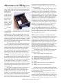
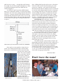
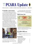
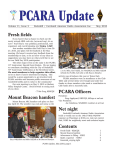
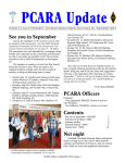
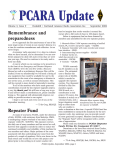
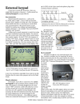
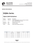
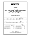
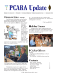
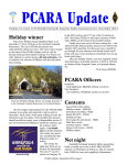
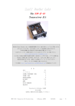
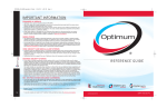
PCARA Update
Volume 5, Issue 1
Peekskill / Cortlandt Amateur Radio Association Inc.
January 2004
New for 2004!
Field Day Results
There is a change in the
line-up of officers for 2004. I
would like to take this
opportunity to welcome Joe,
WA2MCR as the newly
elected Vice President of
PCARA. On behalf of the
membership, I would like to
thank Bob, N2CBH for his
years of service as PCARA
Vice President. Through Bob’s
leadership, PCARA was able
Joe, WA2MCR at
to accomplish many things
Field Day 2003.
that would not have been
possible without it. Bob, Thank you.
There has been discussion of PCARA sponsoring a
Technician Class Course
during ’04. If you would be
interested in either teaching
or enrolling in the class,
please contact Malcolm,
NM9J or one of the officers.
I would like to wish
everyone and their families a
very Happy and Healthy New
Year. Hope to see you all at
Bob, N2CBH at Field
the January 4th meeting, we
Day. Bob has organized
have another busy year to
PCARA’s three Field Days
plan for!
and coordinates PCARA’s
– 73 de Greg, KB2CQE
three repeaters.
December’s QST includes results for Field Day.
You’ll remember that the weekend of June 28-29 was
very pleasant and PCARA ran up a record score. Here
are the results as reported in QST:
Peekskill/Cortlandt ARA, W2NYW:
This score placed PCARA 201st nationally out of
421 entries in category 2A. Read on for a comparison
with our friends in neighboring radio clubs.
PCARA was 8th out of 15 in category 2A for the
Hudson Division, and 33rd out of 81 entries for all
categories in the Hudson Division. The club was 7th out
of 22 entries in the ENY Section, behind leader
Poughkeepsie ARC, third place Yonkers ARC and fifth
place WECA. In fact we were top station (out of three
entries) for category 2A in ENY, ahead of PEARL and
Schenectady Museum ARA.
Full results are in December 2003 QST page 88, or
in the online scores database available to ARRL members at http://www.arrl.org/contests/results
Kevin N2KZE operating Field Day 2003 with Alan logging.
Contents
New for 2004, KB2CQE
Field Day Results
Adventures in DXing, N2KZ
Review - Yaesu VX-2, N2CBH
Node news
The perfect speaker
Antenna trials
Don’t leave the room
QSOs: 733, Power output: 2 (<150W), Participants: 11,
total score: 2,328, ARRL section: ENY.
1
1
2
4
4
5
6
7
PCARA Officers
President:
Greg Appleyard, KB2CQE
Vice President:
Joe Calabrese, WA2MCR;
Secretary/Treasurer:
Mike Aiello, N2HTT
PCARA Update, January 2004, page 1
kb2cqe @ arrl.net
wa2mcr @ arrl.net
n2htt @ arrl.net
Adventures in DXing -N2KZ
It has been a busy month filled with many adventures. A good friend, Lonnie NY2LJ, offered me a trial
run of another QRP CW kit he built. This time it was a
Small Wonder
Labs DSW-II, a
miracle designed
by Dave Benson,
K1SWL. Producing 4 watts of
power on 20
meters, it weighs
about 12 ounces
and can be held
in the palm of
your hand.
It is truly
tiny!
Small Wonder Labs’ DSW-II QRP single
I enjoyed
this marvel for a band CW transceiver for 7 or 14 MHz
weekend with
amazing results. Unlike the Small Wonder Labs RockMite, the DSW-II is continuously tunable. If you push
down a mini toggle switch, the unit will send you what
frequency you are tuned to in Morse numbers. 14.0300
would read back to you as “3 - 0 - 0.” The tuner also
has a useful RIT feature and the ability to tune to WWV
time signals broadcast on 15 MHz.
The DSW-II has one quirk, which really threw me
at first. I turned the rig on and raised what I thought
was the audio control wide open. The receiver sounded
really hot with many stations apparent up and down
the band. I sent CQ to try my luck. I got an instant
reply from N1KSN, Andy, in Menasha, Wisconsin. Keep
in mind the DSW-II was connected to my 20-meter
dipole with no antenna tuner. Bingo! The rig must be
working.
I had a rewarding and effortless QSO. The DSW-II
has a built-in keyer with very smooth QSK. The receiver
held Andy’s signal from Wisconsin without any problem. I turned down the volume since he was pounding
in. After half an hour or so, we said 73. The band
seemed dead as a doornail. In fact, it seemed too dead.
The background noise was gone and I heard no stations
at all. Did a winter static hit blow out the front end?
What’s going on?
The answer is simple. The gain control is not for
AF. It’s for RF. I don’t think I have ever seen a rig
designed like this before. I wish I could talk to Dave,
K1SWL, to ask him why he decided to do this. As
designed, it is a workable system, but it does take some
time to get used to. During periods of severe signal
abuse from megawatt short-wave broadcasters you can
hear a wisp of their signals leak into the DSW-II’s front
end, but you have to really listen for it. Its receive
bandwidth is nominally 500 Hz which serves you well
for CW operation.
Construction of the rig is nearly effortless. There
are only four toroids to wind. The unit requires no
alignment. Leave your test equipment on your bench!
The estimated assembly time is six hours. A 40-meter
version is available, as well. The RF output power is
adjustable from nearly four watts to nearly zero should
“high power” seem like too much luxury or a lack of
challenge to you. I ran this rig on 8 AA batteries for
hours and hours without any noticeable change in
performance. You can use any power source from 8 to
15 volts of DC. The current draw on receive is only 55
milliamps. If you connected this rig to a charged car
battery, you could probably operate for years!
If I have piqued your curiosity, take a look at
http://www.smallwonderlabs.com where the DSW-II
manual can be downloaded. The purchase price is $150
direct from Small Wonder Labs. If you are looking for
big performance for little dollars, this rig could provide
you with many hours of fun.
DTV: Looking for adventure at a higher baud rate?
Investigate the world of digital television! I have been
experimenting with an over-the-air set top box tuner
using my array of television antennas to see what
programming is available in our area. I feel as if I have
jumped back 55 years to the beginnings of television.
Only some channels are broadcasting in DT, with some
odd surprises. HD programming is only available
during very limited hours, mostly in the evening. It’s
amazing how this technology still seems like it is in its
fetal stages years after its introduction.
I managed to pull in nine program streams at my
QTH near Goldens Bridge, New York, just south of
Brewster off I-684.
Here’s a basic digital TV channel guide:
22 - WLIW PBS digital feed and SD Ch. 21 feed
27 - WTBY Trinity Christian Broadcasting Poughkeepsie
33 - WFSB CBS Hartford (analog channel 3)
44 - WNYW “Fox 5” and WWOR “UPN 9”
45 - WABC
52 - WEDW CPTV Connecticut (analog channel 49)
56 - WCBS
57 - WLNY Long Island (analog channel 55)
Missing in action were WNBC, WPIX and WNET
from New York. I had also heard that WNYE was on the
air from Brooklyn with PBS programming. I saw no
signal from them, either.
One interesting attribute of DTV is the ability to
send more than one program stream per carrier. Channel 44 carried both Fox 5 and UPN 9 signals. Using an
enormous remote control, you can key in 44-1 or 44-2
PCARA Update, January 2004, page 2
to distinguish between the feeds.
WLIW, analog PBS channel 21 from
Long Island, also had two feeds on
their signal. Channel 22-1 is a
continuous feed of PBS Digital programs
in HDTV. Channel 22-2 is a digital
version of their analog programming.
I found the ability to grab signals easy and forgiving. Weak signals would lock in within a wide range of
antenna bearing towards the transmitter. Only the
weakest signals, like Channel 33 from Hartford, needed
to be dead-on to lock them in. The channels are also
mapped to the receiver display. Key in 45 for WABC and
you will see 7-1 in the display referring to their overthe-air analog signal on Channel 7. If you can see
reasonable quality analog TV pictures from New York
City with an antenna, especially on the UHF channels,
you should be able to lock in digital TV with no problem.
Digital TV broadcasts also have the ability to send
several versions of captioning (many stations had
English and Spanish captions available) and other
helpful data such as program titles and length and
what type of digital television you are watching. There
are currently 18 different “standards” of DTV relating
mostly to the level of definition presented. Most common are 1080i (1080 lines interlaced), 720p (720 lines
progressive) and 480p (480 lines progressive). 480p is
considered the digital equivalent to analog TV quality.
There are other sources of digital HDTV that I
have not yet experienced. Local cable companies
suggest having feeds of HD programming, but I haven’t
seen it yet. Keep in mind that over-the-air digital has no
connection to what cable companies call “Digital
Cable.” Digital cable refers to how the signals are
processed and delivered to your home almost always in
standard definition. Digital cable is almost always not
high definition television.
Both DirecTV and Dish Network provide a handful
of HDTV via satellite, most notably HD feeds of
Showtime, HBO and a HD-only feed called HDNet.
HDNet is a feed provided as a demonstration channel
with a repetitive schedule of programs from a multitude of sources. Also worth noting is a new service
from Rainbow Programming on Long Island called
VOOM. This service has no connection to Dr. Seuss and
The Cat in the Hat. It is a brand new service catering
especially to HD viewers as a single source to receive
HD programming, also delivered by satellite.
To gain a better understanding of what is being
offered in HDTV, take a look at: http://
www.titantv.com/ttv/home/HDTVUpdate.aspx This is a
site related to a web service called Titan TV that acts as
a HD version of TV Guide. Another site that is a must:
http://www.lge.com/experience/yourbetterlife/
digitalTV.jsp
Here you will find great inspiration to purchase an
HDTV system from Korean manufacturer LG (formerly
known as Lucky Goldstar or simply
Goldstar.) Read about the life of husband
and pregnant wife. A good 30-second
giggle is guaranteed!
CW: Want to practice code without being on the air?
You can now send CW via the Internet using a server in
Australia. Download free software for “CW Communicator” at: http://www.mrx.com.au/. Install the application on your computer. Establish an Internet connection. It’s easy to set up for operation. Your down-arrow
key on your keyboard is your straight key. You can
attach an external key or keyer to a serial port on your
computer, if you wish.
First, click on the icon that looks like little slidefader volume controls. Go to “Morse Key” and click on
“manual,” “keyboard,” and “reset method” and save
your settings by clicking “close”. Make sure your
computer audio is on. Press the down-arrow key and
the box in the upper left hand corner should go white
and you should hear your keying. Now you are ready.
Next, go to the first icon that looks like a globe.
Here you connect to the server. Enter your callsign. Hit
“connect” and you will be connected to the server.
Unless you enter another virtual channel in the “Morse
Key” box, you will default to the calling channel of
1000. After you are connected, click the icon that looks
like a computer monitor to reveal all the operators who
are communicating on the virtual channels. Go have an
Internet CW QSO!
I have already worked several hams and non-hams
from around the world on this system. There is no
QRN, QRM or QSB, but there is sometimes a bit of a lag
when Internet traffic is high. It’s a whole new way of
sending code, and a great way to practice your abilities
before you earn HF privileges. Try it out today!
Finally, please note that New Year’s Eve and New
Year’s Day is a sacred time for all CW enthusiasts. From
0000 UTC to 2359 UTC January 1, 2004, the ARRL
sponsors “Straight Key Night.” SKN is a casual contest
encouraging CW operators of all skill levels to get on
the air with their straight keys. No bugs, keyers or
computers are allowed! This is a wonderful opportunity
for testing your CW wings and meeting many, many
operators who are usually not on this mode. Contacts
can be made on any band within the allocations for
your level of license. Listen for many hams sending “CQ
SKN” and sending “SKN” instead of K when turning a
conversation back to another ham. For more details,
please see: http://www.arrl.org/contests/rules/2004/
skn.html
Until next month, happy trails from the Old Goat,
— N2KZ Karl
PCARA Update, January 2004, page 3
Review: Yaesu
VX-2 – N2CBH
Recently, I tagged along with
my wife on a business trip to Las
Vegas, Nevada. With not much to do
one day I took a stroll over to the
local AES store with the idea of
picking up a Yaesu VX-2. Many Yaesu
products were being offered with a
rebate attached until the end of the
2003 so I couldn’t resist. The unit
normally sells for $179.00 but with a
fifty dollar rebate the price was an
irresistible $129.00!
I walked back to the hotel
where we were staying and opened Yaesu’s new VX-2R
the box and immediately charged the lightweight dual
battery. Later that afternoon the rig band HT.
was ready to try out. The user
manual is clear and easy to understand. Yaesu uses a
standard type menu driven system for most of their
products. If you learn one, you have most of them
covered. Basic capabilities include dual band VHF/UHF
transceiver with wide band receiving capability from
500 kHz to 1.0 GHz, cellular blocked. This includes
wide band reception in the FM broadcast band. Shortwave and AM broadcast band listening are possible but
an external antenna is definitely required. The power
output is 1.5 watts high power on VHF and 1 watt high
power on UHF. The low power setting is 0.5 watts on
both bands. The unit utilizes a 1000 mAH lithium ion
battery pack which charges quickly in 2.5 hours and
has excellent stamina. I was pleased with the battery
life to say the least!
Rather than tell you everything there is to know
about this rig, I would like to focus on some things that
impressed me. As I said earlier, the user manual is very
straightforward. I usually have some difficulty with a
new radio but this one programmed easily the first time
with little frustration. In no time I had about 10 or 15
memories filled and had the Yaesu menu system figured
out. Once you enter the frequency of interest from the
VFO mode you can enter the menu system by pressing
one button for one second. The menu has 48 selections.
You simply rotate the function switch to the menu item
and select those parameters that you want. Once all of
the menu items are selected you can program all of
these items into a memory location by pressing another
button. To me, this is simple and easy to understand.
Another thing that impressed me was the small package. This rig is literally the size of a cigarette pack
easily fitting into a shirt pocket. Another feature that I
think is kind of neat is the ARTS™ function. ARTS
stands for Automatic Range Transponder System. ARTS
is a system whereby two ARTS equipped radios can tell
one another that they are in range of one another. This
could be handy for field operations such as rescue or
hiking. Another feature that will come in handy for my
work is the little known transmitter “channel counter”.
The radio has the ability to sniff out transmitting
antennas in close proximity and display the transmitted
frequency. It does this by applying a 50 dB attenuator
to the front end of the receiver so as to only pick up
signals in close proximity to the rig’s antenna. This is
really a great feature. I must confess that I didn’t know
about this feature until I bought the rig! Another
confession is that I haven’t tried this feature out yet!
The VX-2 like many of Yaesu’s handhelds can be
programmed from a PC with additional software and a
programming cable. If you are a real scanner junkie or
like to program all of the available 900 memories, the
software and cable are a must. There are only seven
buttons on the front panel of the rig and it doesn’t sport
a DTMF keypad, but this doesn’t prevent you from
generating DTMF tones. This is done by programming a
string of DTMF tones and then accessing one of the
DTMF memory banks to execute the string. I would say
that this is cumbersome but it probably beats trying to
press microscopically small DTMF buttons!
There are a lot more features to this rig than an
article in a newsletter could possibly hold. I will bring
the rig in for the next PCARA meeting for a little show
and tell. I can tell you that since I brought this rig home
my older Kenwood TH-79 has been gathering dust!
— 73 de Bob, N2CBH
Node news is good news
PCARA members may remember that at the
September 2003 meeting we had a successful demonstration of Internet linking. An IRLP link between
PCARA’s node 4214 and node number 5220 in
Southport, England featured a contact with node owner
Mark, G4EID. (By the way your editor has known Mark
for many a year from my own time in Southport. Mark
was instrumental in introducing me to IRLP during a
visit, and in helping to get the PCARA node on the air.)
Latest news from Southport is that Mark recently
drove 250 miles to Portsmouth in southern England.
There he took the U.S. Technician, General, Extra and
code tests with an overseas V.E. Team and on December
16 was granted the U.S. Extra class call of AI4DC by the
FCC. Mark has requested a 2x1 Vanity call reflecting his
own initials. He should get a chance to use that new
call for the first time on a visit to the U.S.A. later in
2004.
- NM9J
PCARA Update, January 2004, page 4
The perfect speaker
Occasionally I’ll
go on a quest for the
perfect something.
One recent search was
for the perfect loudspeaker.
The first thing to
realize is that the
built-in speaker on
any transceiver is a
long way from being
optimal. How can you
Internal speaker from a Yaesu
expect good quality
from a speaker that is FT-7100 mobile transceiver.
Diameter is a mere 1¾ inches and
less than 2 inches in
5
diameter and less than depth is only /16 inch.
half an inch deep? The second thing to realize is that
different circumstances can require different speaker
characteristics.
HF and Shortwave: You might think that a
loudspeaker frequency response of 300 to 3000 Hz
would be adequate for an SSB transceiver. But suppose
the radio’s general coverage receiver strays out of the
amateur bands from time to time onto the high frequency and medium frequency AM broadcast bands. In
that case, you’ll probably want something better than
“good communications quality”. Those AM broadcast
stations transmit plenty of bass frequencies. One
approach is to connect a full size hi-fi speaker to the
loudspeaker output jack. There is a beneficial side
effect as well — if netting one carrier to another or
tuning AM signals in SSB mode, the bass response of
the speaker will help you adjust for zero-beat.
Perhaps you have a portable shortwave receiver
with a low-power headphone jack. In that case, try
plugging in a pair of amplified computer speakers. The
improvement in audio quality can be quite startling. I
have had good results with Yamaha YST-M7 amplified
speakers and with the Cambridge Soundworks
“PCWorks” model
that includes a
separate subwoofer. If
you run into RF-hum
problems caused by
the speaker power
supply, check the
following article:
http://
home.computer.net/
~pritch/
shortwav.htm.
These Yamaha YST-M7 amplified
A good quality
computer speakers work well with speaker for AM will
a portable shortwave receiver.
work equally well on
single sideband. The transmitted audio bandwidth on
SSB is usually limited to ~300 Hz to 2.8 kHz, so it
won’t matter too much if there is some bass cut below
300 Hz. However, a large speaker makes a big difference if you are monitoring the “wideband sideband”
signals around 14.178 MHz. You will need a receiver
with adequate low-end bandwidth, or you can make
use of your transceiver’s “I.F. shift” control to move bass
frequencies into the SSB filter’s passband.
VHF-UHF FM: You might think that similar
considerations would apply to an external speaker for
your VHF or UHF FM transceiver. Why not simply plug
in a hi-fi loudspeaker and enjoy the high quality that
FM can produce? There’s a very good reason why not
— and it’s called “PL”. These days, many repeaters carry
an ‘encode’ PL or CTCSS tone on the output frequency.
PL is sometimes described as a ‘sub-audible’ tone – but
the frequencies concerned, from 67 to 250 Hz, are well
within the range of normal hearing. If your FM transceiver does not include adequate audio filtering to
remove these low frequency tones, you will hear a
steady hum coming from the loudspeaker while the
repeater is on the air. Use an external speaker with an
extended bass response and the effect will be magnified. If you would like a practical demonstration, try
listening to our PCARA 146.67 MHz repeater on an
Icom IC-706 with a large external speaker. (By the way,
W2NYW/R uses an encode tone of 156.7 Hz.)
So the first requirement for a VHF/UHF FM
speaker is a frequency response that cuts off below 300
Hz. This is fairly easy to arrange – a small diameter
speaker and an inadequate baffle will destroy the bass
response in no time. However, if you will be using the
radio under mobile conditions, a tiny, inefficient
speaker is not such a good idea – your aim is to convert
as much of the radio’s undistorted audio output to
acoustic energy as possible without driving the speaker
into distortion. If you have a noisy vehicle, the louder
the better! There are plenty of mobile speakers available including branded models from Icom and
Kenwood – but I’ve
had the most success
with products from
business radio manufacturers such as Pye
and Motorola. They
know how to make
rugged products that
will stand up to years
of abuse in the harsh
Motorola model contains a large,
environment of a
heavy loudspeaker for mobile use.
motor vehicle. You will
probably need to cut off the original connector and
substitute a standard amateur radio 1/8 inch mono
phone plug to fit the transceiver’s external speaker jack.
- 73 de Malcolm, NM9J
PCARA Update, January 2004, page 5
Antenna trials – NM9J
Antennas can be a trial — especially when things
go wrong high in the air. Here’s how things went wrong
twice one fine December day.
My neighbor, Joe WA2MCR had asked for some
help with his Windom. There was snow on the ground
and Joe’s yard was still soggy but we braved the winter
weather and set forth to investigate the problem.
Joe’s yard is surrounded by tall trees and two of
the tallest were supporting a “Carolina Windom 160
Special”. Joe had been experiencing problems loading
up his transceiver/ATU into this antenna, so it was time
for a closer look.
Radio Works’ Carolina Windom for 80-10 meters
Radio Works’ (http://www.radioworks.com)
Carolina Windom consists of a 133 foot dipole fed with
coax – not in the middle – but 51 feet from one end.
According to the ARRL Antenna Book, this off-center
feed results in unequal currents flowing in the dipole
sections, and as a result, the vertical feeder may also
radiate. Radio Works makes a virtue of this vertical
component. They include a “dedicated matching unit”
at the feed point to match the coax feed line to the
antenna and to “enhance transmission line radiation”.
(This “DMU” is probably a 4:1 or 6:1 transformer.)
Twenty two feet below the DMU is a “Line Isolator”,
which provides “a large inductive reactance at the
Radio Works Carolina Windom viewed from below.
The Line Isolator is nearest to the camera.
insertion point” to eliminate
transmission line radiation
beyond the point where it is
inserted. Radio Works describes the overall design as
an inverted-vertical antenna
located high in the air.
Joe’s “160 Special”
version of the Carolina
Windom has an “improved
DMU and line isolator” to
allow use on 160 meters, as
well as 80-10 meters.
The first thing we
The Carolina Windom’s
checked was overall perfordedicated matching unit
mance. I connected my MFJseemed in good shape...
259 antenna analyzer at the
end of the antenna’s coaxial feeder and made a note of
each resonant frequency — wherever there was a
distinct dip in the SWR. Joe was not very satisfied with
the results, so we lowered the antenna and examined
the connections. The “dedicated matching unit” seemed
to be in good shape, but the “line isolator” was less
encouraging. First of all, its coaxial connector was
loose, then we
saw water
dripping from
the plastic
enclosure.
Inspection of
the top of the
...but the line isolator had something
isolator —
wrong inside...
where the
vertical coaxial feeder enters — showed a far from
perfect seal.
The plastic enclosures consist of lengths of PVC
pipe, sealed off with end caps. Unfortunately, Radio
Works seemed to have secured the end caps with PVC
cement and removing them would have required
destruction with a hacksaw — so we coiled up the
antenna and Joe took
it indoors to dry out.
Later I checked on
Google and found five
other people who had
experienced problems
with water entering
their Carolina
Windoms and spoiling
the performance.
(More attention needs
to be paid to waterproofing the sections
of plastic pipe — one
approach might be to Joe shows where water had entered
the top of the line isolator.
fill the internal space
PCARA Update, January 2004, page 6
with hot wax or epoxy — though this would increase
the weight. An even better approach might be to adopt
a design that eliminates the heavy DMU and line
isolator altogether.)
Joe decided to put his previous G5RV antenna
back up as a temporary measure. It did not take long to
attach the wire ends to the existing halyards and haul it
into place. I connected the MFJ-259 antenna analyzer –
and found that disaster had struck. There were no dips
at all in the SWR readings, and connecting the antenna
to Joe’s transceiver gave poor loading and indifferent
reception.
G5RV antenna for 80-10 meters as used by Joe, WA2MCR.
Once again we went outside to inspect the antenna. Joe’s commercial G5RV has a current choke
between the coaxial feeder and the twin feeder that
runs up to the center of the
dipole. The center insulator
was in good shape, but the
current choke, mounted
once again inside a length
of plastic pipe, looked
rather doubtful with only
three screws holding the
SO-239 connector to the
base. We disassembled the
plastic pipe and found that
the outer conductor of the
coaxial cable was no longer
connected to the SO-239.
The bolt that should have
completed the circuit had
simply sheared off.
It did not take too long
to replace the broken
hardware and hoist Joe’s
Current choke on Joe’s
G5RV antenna.
G5RV antenna back into
place. Walking back into the radio room, we heard the
welcome sound of CHU-Canada booming out of the
receiver on 3330 kHz – and a quick check with the
MFJ-259 showed that the antenna was now resonant in
or near the usual amateur bands from 80 to 10 meters.
Joe was happy when his TS-530 transceiver and MFJ
antenna tuning unit loaded up satisfactorily. He later
reported that the G5RV was performing in a similar
manner to the Carolina Windom, but with less pickup
of noise — probably because of the reduced vertical
component from this fully balanced antenna.
Conclusions: With antennas, it seems that
simpler is better. The more complicated hardware you
have outside, the more there is to go wrong. Joe’s
experience shows that dipole antennas suspended
between tree limbs can experience a lot of strain and
need to be checked from time to time. Incidentally, Joe
uses a system of water-filled bottles as counterweights
to maintain steady tension in the antenna halyards
while the tree branches are moving around in the wind.
A second conclusion concerns the modern practice
of enclosing baluns and chokes in sections of plastic
water pipe — this may not be ideal for wire dipole
antennas. The PVC pipe is heavy, solvent-welded pipe
fittings cannot be removed easily and the overall
assembly can become waterlogged if there are any
holes in the top or sides.
The G5RV antenna, with its balanced dipole and
lightweight twin lead for the first 30 feet, seems to be a
better mechanical design than the Carolina Windom...
but perhaps the Windom is a superior multiband
antenna to the G5RV? It’s hard to say, but if you want
to read further, take a look at W4RNL’s series of articles
(9, 10, 11) on “Off-Center-Fed Dipoles” at http://
www.cebik.com/gup/groundup.html.
- Malcolm, NM9J
Don’t leave the room!
PCARA meeting “At the Reef” restaurant, December 7, 2003,
when Joe WA2MCR was elected to the post of Vice President.
PCARA Update, January 2004, page 7
Peekskill / Cortlandt
Amateur Radio Association
PCARA Calendar
Sunday Jan 4: January meeting, HVHC, 3:00 P.M.
Mail: PCARA, PO Box 146, Crompond, NY 10517
E-Mail: [email protected]
Web site: http://www.pcara.org
Sun Jan 18: ARRL New York/Long Island Section Convention,
Long Island Mobile ARC, East Woods School in Oyster Bay, Long
Island.
Sun Feb 29: LIMARC Long Island Hamfair, Levittown Hall,
201 Levittown Pkwy, Hicksville, NY. 9:00 am.
PCARA Update Editor: Malcolm Pritchard, NM9J
E-mail: NM9J @ arrl.net
Newsletter contributions are always very welcome!
PCARA Information
PCARA is a Non-Profit Community Service Organization. PCARA meetings take place the first Sunday
of each month at 3:00 p.m. in Dining Room B of the
Hudson Valley Hospital Center, Route 202, Cortlandt
Manor, NY 10567. Drive round behind the main hospital building and enter from the rear (look for the
oxygen tanks). Talk-in is available on the 146.67
repeater.
Hamfests
VE Test Sessions
Jan 4: Yonkers ARC, Yonkers Police Dept., 1st Precinct, E Grassy
Sprn Rd, 8:30 A.M. Contact: D. Calabrese, 914 667-0587.
Jan 12: Split Rock ARA, Hopatcong High School, Rm C-1,
Hopatcong NJ. 7:00 p.m. Contact Sid Markowitz, 973 724-2378.
Jan 23: Bergen ARA, Westwood Regional HS, 701 Ridgewood
Rd, Washington Township NJ. 7:00 P.M. Contact Donald Younger
201 265-6583.
Jan 26: Columbia Univ ARC, Watson Labs, 612 W 115th St.
New York, NY, 6:30 p.m. Contact Alan Crosswell, 212 854-3754.
Feb 1: Yonkers ARC, Yonkers Police Dept., 1st Precinct, E Grassy
Sprn Rd, 8:30 A.M. Contact: D. Calabrese, 914 667-0587.
PCARA Repeaters
W2NYW:
146.67 MHz -0.6, PL 156.7Hz
KB2CQE:
449.925MHz -5.0, PL 179.9Hz
(IRLP node: 4214)
N2CBH:
448.725MHz -5.0, PL 107.2Hz
Peekskill / Cortlandt Amateur Radio Association Inc.
PO Box 146
Crompond, NY 10517
PCARA Update, January 2004, page 8