1
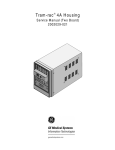
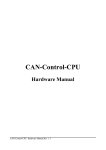
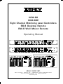
VCM-88
VCM-88E
Eight Channel Matrixing Level Controllers
RD-8 Desktop Remote
RW-8 Wall Mount Remote
Operating Manual
-6 0 +6
-12
-23
Sig Thr
Sig Thr
+12
+18
-18
-6 0 +6
-12
-23
Sig Thr
-6 0 +6
+12
-12
+18
-18
+23
dBu
-23
Sig Thr
Sig Thr
+12
+18
-18
+23
dBu
+23
dBu
-6 0 +6
-12
+12
+18
-18
-23
-6 0 +6
-12
-23
Sig Thr
+12
+18
-18
+23
dBu
-6 0 +6
-12
-23
Sig Thr
+12
+18
-18
+23
dBu
+23
dBu
∞
On
∞
Gain (dB)
ASHLY AUDIO INC.
847 Holt Road Webster, NY 14580-9103 Phone: (585) 872-0010
Toll-Free: (800) 828-6308 Fax: (585) 872-0739
www.ashly.com
Operating Manual - VCM-88, VCM-88E, RD-8, RW-8 Level Controllers
Table Of Contents
1 Introduction . . . . . . . . . . . . . . . . . . . . . . . . . . . . . . . . . . . . . . . . . . . . . . . . . . . . . . . . . . . . . . . . . . . . . . . 4
2 Unpacking . . . . . . . . . . . . . . . . . . . . . . . . . . . . . . . . . . . . . . . . . . . . . . . . . . . . . . . . . . . . . . . . . . . . . . . . . 4
3 AC Power Requirements . . . . . . . . . . . . . . . . . . . . . . . . . . . . . . . . . . . . . . . . . . . . . . . . . . . . . . . . . . . . . 4
4 Security Covers . . . . . . . . . . . . . . . . . . . . . . . . . . . . . . . . . . . . . . . . . . . . . . . . . . . . . . . . . . . . . . . . . . . . . 4
5 VCM-88, VCM-88E Features . . . . . . . . . . . . . . . . . . . . . . . . . . . . . . . . . . . . . . . . . . . . . . . . . . . . . . . . . . 5
5.1 Signal Present LED . . . . . . . . . . . . . . . . . . . . . . . . . . . . . . . . . . . . . . . . . . . . . . . . . . . . . . . . . . . . . . 5
5.2 Limiter Threshold Control and Indicator . . . . . . . . . . . . . . . . . . . . . . . . . . . . . . . . . . . . . . . . . . . . . 5
5.3 Master Attenuation Control . . . . . . . . . . . . . . . . . . . . . . . . . . . . . . . . . . . . . . . . . . . . . . . . . . . . . . . 5
5.4 Digital Remote Control Status Indicator . . . . . . . . . . . . . . . . . . . . . . . . . . . . . . . . . . . . . . . . . . . . . . 5
5.5 Digital Remote Control Disable Switch . . . . . . . . . . . . . . . . . . . . . . . . . . . . . . . . . . . . . . . . . . . . . . 5
5.6 Power Switch . . . . . . . . . . . . . . . . . . . . . . . . . . . . . . . . . . . . . . . . . . . . . . . . . . . . . . . . . . . . . . . . . . 5
5.7 Master Output and Channel Pass Through . . . . . . . . . . . . . . . . . . . . . . . . . . . . . . . . . . . . . . . . . . . 6
5.8 DC Control . . . . . . . . . . . . . . . . . . . . . . . . . . . . . . . . . . . . . . . . . . . . . . . . . . . . . . . . . . . . . . . . . . . . 6
5.9 Remote Control Data Input . . . . . . . . . . . . . . . . . . . . . . . . . . . . . . . . . . . . . . . . . . . . . . . . . . . . . . . 6
5.10 Device ID Select . . . . . . . . . . . . . . . . . . . . . . . . . . . . . . . . . . . . . . . . . . . . . . . . . . . . . . . . . . . . . . . . 6
5.11 RS-232 Input . . . . . . . . . . . . . . . . . . . . . . . . . . . . . . . . . . . . . . . . . . . . . . . . . . . . . . . . . . . . . . . . . . 6
5.12 RS-232 Mode Switch (VCM-88E only) . . . . . . . . . . . . . . . . . . . . . . . . . . . . . . . . . . . . . . . . . . . . . . . 6
5.13 Data Protocol Selector Switches (VCM-88E only) . . . . . . . . . . . . . . . . . . . . . . . . . . . . . . . . . . . . . . . 7
5.14 MIDI (VCM-88 only) . . . . . . . . . . . . . . . . . . . . . . . . . . . . . . . . . . . . . . . . . . . . . . . . . . . . . . . . . . . . . 7
5.15 Slave Data In/Out (VCM-88E only) . . . . . . . . . . . . . . . . . . . . . . . . . . . . . . . . . . . . . . . . . . . . . . . . . 7
6 RD-8/RW-8 Remote . . . . . . . . . . . . . . . . . . . . . . . . . . . . . . . . . . . . . . . . . . . . . . . . . . . . . . . . . . . . . . . . . 7
6.1 Channel and Master On Switch . . . . . . . . . . . . . . . . . . . . . . . . . . . . . . . . . . . . . . . . . . . . . . . . . . . . 7
6.2 Channel and Master Fader . . . . . . . . . . . . . . . . . . . . . . . . . . . . . . . . . . . . . . . . . . . . . . . . . . . . . . . 7
6.3 Remote Disable Indicator . . . . . . . . . . . . . . . . . . . . . . . . . . . . . . . . . . . . . . . . . . . . . . . . . . . . . . . . . 7
6.4 Data Connection . . . . . . . . . . . . . . . . . . . . . . . . . . . . . . . . . . . . . . . . . . . . . . . . . . . . . . . . . . . . . . . 7
7 Audio Connections and Cables . . . . . . . . . . . . . . . . . . . . . . . . . . . . . . . . . . . . . . . . . . . . . . . . . . . . . . . 8
7.1 Balanced and Unbalanced Signals . . . . . . . . . . . . . . . . . . . . . . . . . . . . . . . . . . . . . . . . . . . . . . . . . . 8
7.2 Input Connections . . . . . . . . . . . . . . . . . . . . . . . . . . . . . . . . . . . . . . . . . . . . . . . . . . . . . . . . . . . . . . 8
7.3 Output Connections . . . . . . . . . . . . . . . . . . . . . . . . . . . . . . . . . . . . . . . . . . . . . . . . . . . . . . . . . . . . . 8
8 Input
8.1
8.2
8.3
and Output Configuration Options . . . . . . . . . . . . . . . . . . . . . . . . . . . . . . . . . . . . . . . . . . . . . . . 9
Single Connector Insert . . . . . . . . . . . . . . . . . . . . . . . . . . . . . . . . . . . . . . . . . . . . . . . . . . . . . . . . . . 9
Single Channel Pass-Through . . . . . . . . . . . . . . . . . . . . . . . . . . . . . . . . . . . . . . . . . . . . . . . . . . . . . . 9
Input/Output Matrixing . . . . . . . . . . . . . . . . . . . . . . . . . . . . . . . . . . . . . . . . . . . . . . . . . . . . . . . . . . 9
9 Data
9.1
9.2
9.3
9.4
9.5
Connections and Configurations . . . . . . . . . . . . . . . . . . . . . . . . . . . . . . . . . . . . . . . . . . . . . . . . . 10
Standard Remote Data Control . . . . . . . . . . . . . . . . . . . . . . . . . . . . . . . . . . . . . . . . . . . . . . . . . . . . 11
AMX and Legacy . . . . . . . . . . . . . . . . . . . . . . . . . . . . . . . . . . . . . . . . . . . . . . . . . . . . . . . . . . . . . . . . 11
DC Control Voltage Connection . . . . . . . . . . . . . . . . . . . . . . . . . . . . . . . . . . . . . . . . . . . . . . . . . . . . 11
RS-232 Control and Protea System Software . . . . . . . . . . . . . . . . . . . . . . . . . . . . . . . . . . . . . . . . . . 11
MIDI Implementation . . . . . . . . . . . . . . . . . . . . . . . . . . . . . . . . . . . . . . . . . . . . . . . . . . . . . . . . . . . . 11
2
Operating Manual - VCM-88, VCM-88E, RD-8, RW-8 Level Controllers
10 Troubleshooting Tips . . . . . . . . . . . . . . . . . . . . . . . . . . . . . . . . . . . . . . . . . . . . . . . . . . . . . . . . . . . . . . . 12
10.1 No Output . . . . . . . . . . . . . . . . . . . . . . . . . . . . . . . . . . . . . . . . . . . . . . . . . . . . . . . . . . . . . . . . . . . . 12
10.2 Very Little Output Signal . . . . . . . . . . . . . . . . . . . . . . . . . . . . . . . . . . . . . . . . . . . . . . . . . . . . . . . . . 12
10.3 Distorted Sound . . . . . . . . . . . . . . . . . . . . . . . . . . . . . . . . . . . . . . . . . . . . . . . . . . . . . . . . . . . . . . . . 12
10.4 Excessive Hum or Noise . . . . . . . . . . . . . . . . . . . . . . . . . . . . . . . . . . . . . . . . . . . . . . . . . . . . . . . . . . 12
11 Warranty Information . . . . . . . . . . . . . . . . . . . . . . . . . . . . . . . . . . . . . . . . . . . . . . . . . . . . . . . . . . . . . . 13
12 Specifications . . . . . . . . . . . . . . . . . . . . . . . . . . . . . . . . . . . . . . . . . . . . . . . . . . . . . . . . . . . . . . . . . . . . . 13
13 Dimensional Drawings and Schematics . . . . . . . . . . . . . . . . . . . . . . . . . . . . . . . . . . . . . . . . . . . . . . . 14
14 Common Applications . . . . . . . . . . . . . . . . . . . . . . . . . . . . . . . . . . . . . . . . . . . . . . . . . . . . . . . . . . . . . . 14
15 Schematics . . . . . . . . . . . . . . . . . . . . . . . . . . . . . . . . . . . . . . . . . . . . . . . . . . . . . . . . . . . . . . . . . . . . . . . 15
15.1 VCM-88 . . . . . . . . . . . . . . . . . . . . . . . . . . . . . . . . . . . . . . . . . . . . . . . . . . . . . . . . . . . . . . . . . . . . . . 15
15.2 VCM-88E . . . . . . . . . . . . . . . . . . . . . . . . . . . . . . . . . . . . . . . . . . . . . . . . . . . . . . . . . . . . . . . . . . . . . 16
15.3 RD-8 and RW-8 . . . . . . . . . . . . . . . . . . . . . . . . . . . . . . . . . . . . . . . . . . . . . . . . . . . . . . . . . . . . . . . . 20
The lightning flash with arrowhead
symbol, within an equilateral triangle, is
intended to alert the user to the presence
of uninsulated "dangerous voltage" within
the product's enclosure that may be of
sufficient magnitude to constitute a risk
of electric shock to persons.
CAUTION
RISK OF ELECTRIC SHOCK
DO NOT OPEN
The exclamation point within an eqilateral
triangle is intended to alert the user to the
presence of import ant operating and
maintenance instructions in the literature
accompanying the device.
TO REDUCE THE RISK OF ELECTRIC SHOCK, DO NOT REMOVE COVER. NO USER SERVICEABLE PARTS INSIDE.
REFER SERVICING TO QUALIFIED SERVICE PERSONNEL.
TO REDUCE THE RISK OF FIRE OR ELECTRICAL SHOCK,
DO NOT EXPOSE THIS APPlIANCE TO RAIN OR MOISTURE.
TO REDUCE THE RISK OF FIRE, REPLACE ONLY WITH
SAME TYPE FUSE. REFER REPLACEMENT TO QUALIFIED SERVICE PERSONNEL.
WARNING:
THIS APPARATUS MUST BE EARTHED
3
Operating Manual - VCM-88, VCM-88E, RD-8, RW-8 Level Controllers
1. Introduction
2. Unpacking
One of the many useful circuits to be developed
for audio use is the VCA, or voltage controlled amplifier.
A VCA circuit allows for accurate, low distortion level control without signal degradations encountered when using
mechanical controls or long signal paths. VCA circuits can
be found in compressor/limiter/expanders, noise gates, noise
reduction systems, automatic mixers, VCA-Bus consoles,
and other places where remote control or fast automatic
system response is required. Designers at Ashly felt there
was still a need for high quality VCA control which could
be incorporated into professional sound systems without
unnecessarily high cost or complication.
As a part of our system of quality control, every
Ashly product is carefully inspected before leaving the factory to ensure flawless appearance. After unpacking, please
inspect for any physical damage. Save the shipping carton
and all packing materials , as they were carefully designed
to reduce to minimum the possibility of transportation damage should the unit again require packing and shipping. In
the event that damage has occurred, immediately notify your
dealer so that a written claim to cover the damages can be
initiated.
The Ashly VCM-88 and the similar VCM-88E
(euro-block connector model) provide eight fully-independent VCA channels in a single unit capable of limiting, remote level control, and mixing. When connected to the
Ashly RD-8 (desktop) or RW-8 (wall-mount) remote controller, direct DC control, or Ashly's Protea System Software, the VCM-88(E) controls individual channel and master levels with a range of -75dB to +20dB. Each VCA channel has separate input and output jacks for patching into
line-level signal paths, and can be reconfigured to use single
connector insertion for patching into mixing consoles.
When using the VCM-88(E) as a mixer (using the master
output), each channel’s input can be configured to “passthrough” to its output for daisy chaining multiple units together.
The Ashly VCM-88E maintains the features of the
VCM-88 while replacing 1/4" jacks with Euroblock connectors. It also adds bi-directional data communications,
non-volatile memory of level settings, and uses all recessed
face panel controls specifically for fixed installations.
The right to any claim against a public carrier can
be forfeited if the carrier is not notified promptly and if the
shipping carton and packing materials are not available for
inspection by the carrier. Save all packing materials until
the claim has been settled.
3. AC Power Requirements
A standard IEC-320 AC inlet is provided on the
rear panel to accept the detachable power cord shipped with
the unit. Units distributed within the United States are
preselected for 120VAC, 60Hz and should be plugged into
a standard NEMA 5-15 3-wire grounded AC receptacle.
Most units distributed outside the US are preselected and
labeled for 240VAC, 50-60Hz and are shipped with the
appropriate power cord.
The VCM-88(E) will perform normally from 100
to 125 volts AC. An internal line fuse is used. In the event
of fuse failure, refer to a qualified service technician for
servicing. Maximum power consumption of the VCM88(E) is 18 watts.
4. Security Covers
The RD-8 remote controller is a compact slidefader
remote level controller which can be desk-top situated or
rack-mounted into two rack spaces (3.5 inches) using the
RD8-RM optional mounting bracket. This remote controller is also available as the RW-8 for wallmounting into a
standard 4-gang electrical box. The RD-8 controls the audio levels of the VCM-88(E) over a standard XLR snake
cable or shielded twisted pair. As it is powered entirely by
the VCM-88(E), no batteries or remote power supply are
necessary for either RD-8 or RW-8. The RD-8 can communicate to the VCM-88(E) over a 24 gauge snake cable in
excess of 1/4 mile (400m). The RD-8 also pulse-shapes
the digital waveform to eliminate digital crosstalk noise into
adjacent audio channels.
For installations where it is desirable to protect the
front panel controls from tampering or accidental
misadjustment, use the Ashly security cover, which is available in both single and double rack space sizes. Installation is simple and does not require removal of the equipment from your rack. See your Ashly dealer for details.
4
Operating Manual - VCM-88, VCM-88E, RD-8, RW-8 Level Controllers
Sig Thr
Sig Thr
Sig Thr
Sig Thr
Sig Thr
Sig Thr
5. VCM-88, VCM-88E Features
5.1 Signal Present LED
Each channel has a green LED to indicate input
signal present (app. -20dBu). Since the LED is referencing the audio signal prior to the VCA circuit, the LED will
continue flashing even if the channel level is turned down.
5.2 Limiter Threshold Control and Indicator
The recessed Limiter Threshold trimpot adjusts the
signal threshold above which the limiter will become active. The units of this threshold dial are dBu where 0dBu =
0.775Vrms. The limiter is a peak-detecting true VCA type
limiter with very low distortion. The input to output ratio
of the limiter is approximately 10 to 1 with a relatively fast
attack and moderate release time behavior. The adjacent
yellow threshold LED indicates when the limiter circuit has
been activated by an audio signal above the threshold level.
To disable the limiter on any given channel, simply rotate
its threshold adjustment fully clockwise to +23dBu, which
is the maximum input signal of the unit.
Sig Thr
∞
stopped and continue to operate as if there were no changes
happening. Reconnecting the remote data signal with the
VCM-88(E) still operating will instantly change the channel level settings to wherever the controller is currently set.
Note: If the VCM-88 AC power is switched on with no data
reception, all eight channels and the master level will default to unity gain (0dB). The VCM-88E will remember the
last level settings when the AC power is switched off and
will restore these settings on power-up.
5.5 Digital Remote Control Disable Switch
This switch disables the RD-8 remote controller
and returns all eight channels to unity gain. On the VCM88E, this switch is Protea Software selectable to provide
either unity gain or the last level settings before the remote
is disabled. The adjacent red LED indicates when this
switch is depressed. The nearby green Remote Active indicator will go off when the remote is disabled because the
RD-8 does not send any data when it is disabled. After
releasing the remote disable switch, all channels return to
their respective levels set by the RD-8 remote controller or
software control.
5.3 Master Attenuation Control
5.6 Power Switch
This control (fully recessed on the VCM-88(E) attenuates all eight channels uniformly, and was designed as
a simple means of turning down all eight audio channels at
the VCM-88(E) location in the event of feedback or other
sound system problems. Normally this control should be
set fully clockwise at 0dB attenuation.
5.4 Digital Remote Control Status Indicator
On the VCM-88, this front-panel push-button
switches the AC power to the unit. The switch is located
on the back panel of the VCM-88E. A green LED indicates when the unit is powered on. If the green LED does
not light, check to see if the unit is plugged into a live outlet, and that the removable AC cord is firmly plugged into
the VCM-88(E). If there is still no light, refer the unit to a
qualified service technician.
This green LED indicates when the VCM-88(E) is
receiving data from the RD-8, RW-8, or computer control.
In the event of remote control data interruption, the VCM88(E) will lock all settings just before the data reception
5
Operating Manual - VCM-88, VCM-88E, RD-8, RW-8 Level Controllers
RS-232
CAUTI ON
10
12
10K CW
Pin 1-9
RISK OF ELECTRIC SHOCK
DO NOT OPEN
CAUTION
Risk of Electric
Shock. Do
Not Open
VCM-88E
Made In USA
5.7 Master Output and Channel Pass Through
The VCM-88(E) can be used as an eight-in/oneout remote level control for personal monitor mixing using
the Master Output. Multiple VCM-88(E) units can be daisy
chained to produce several unique mixes from the same
program source. To simplify cabling for this application,
the VCM-88(E) has the ability to internally pass each
channel’s input signal directly to its output jack, disabling
that channel’s direct VCA output but eliminating the need
for special “Y” cables. The passed-through channel’s VCA
output is automatically summed to the 200 Ohm pseudobalanced Master Output along with other channels for final output. The gain from any one input channel to Master
Output is -6dB so that a mix of several audio channels will
have approximately the same volume as one of the input
channels. See section 8.2 for channel pass-through details.
5.8 DC Control
A 15 pin female D-Sub connector on the back panel
(12-position Euroblock on the VCM-88E) is used for DC
control of the eight VCA channels and Master Attenuation,
providing a simple and cost-effective method for custom
control of the VCM-88(E). Most electronics hardware
stores will have the male connector complement. The reference DC voltage is also provided, thus requiring only the
male connector, wire, and a 10K ohm potentiometer for
each channel to control audio levels from any reasonable
distance. See section 9.3 for DC Control details.
5.9 Remote Control Data Input
This connector is used for remote control by the
Ashly RD-8 or RW-8, or other third party controllers. AMX
and Crestron are companies which manufacture touchscreen computer interfaces for a variety of control applications, including the VCM-88(E). AMX and Crestron provide a hardware interface which uses the XLR Data In con-
6
nector on the VCM-88 and the Remote RD/RW-8 Euroblock
connector on the VCM-88E. See section 9.1 for AMX and
Crestron interface details.
5.10 Device ID Select
Each VCM-88(E) can be addressed to one of 16
devices, allowing for control of up to 128 channels (16 x 8)
from a single data line. The device ID on the VCM-88E is
selected in binary format from the Device ID DIP switch
on the rear panel. The device ID on the VCM-88 is internally selected with jumpers. See section 9.5 for Device ID
Select DIP switch settings or internal jumper locations.
5.11 RS-232 Input
RS-232 is a bi-directional serial communications
connection which allows computer devices to control other
hardware. Ashly Protea System Software (see section 9.4)
uses RS-232 to control the VCM-88(E), and other third party
sources may use RS-232 as well.
While both the VCM-88 and the VCM-88E have
dedicated RS-232 input jacks, only the VCM-88E RS-232
input is truly bidirectional. RS-232 data is read into the
memory of the VCM-88E and stored, then read back from
memory to get an actual snapshot of the current data settings. This is especially useful to upload to Protea System
Software the current settings of a VCM-88E.
The VCM-88 data is unidirectional in receiving
data only, meaning there is no RS-232 data out from the
unit.
5.12 RS-232 Mode Switch (VCM-88E only)
The RS-232 mode switch is pushed in only when
the VCM-88E RS-232 Input is connected to a PC, and another unit is connected to the Slave Data connector.
Operating Manual - VCM-88, VCM-88E, RD-8, RW-8 Level Controllers
5.13 Data Protocol Selector (VCM-88E only)
5.14 MIDI (VCM-88 only)
These two DIP switches allow selection of four data
protocols. The Standard protocol is selected for use with
current Ashly, AMX, or Crestron controllers. The Protea
Software protocol is selected for use with Ashly's Protea
System Software. The MIDI protocol is used for control
by a MIDI device. The Legacy protocol is selected for control by a legacy Ashly or AMX device. On the VCM-88,
protocols are selected using internal jumpers. See fig. 9.2
for VCM-88 data protocol details.
MIDI In and MIDI Thru jacks allow complete
implementation of the VCM-88 in a MIDI network. An internal jumper selection is required to operate under MIDI
control. For specific details regarding internal selection,
as well as continuous controller numbers and values, see
section 9.5.
5.15 Slave Data In/Out (VCM-88E only)
Multiple VCM-88E units can be placed in the same
control loop using the Slave Data In/Out euroblock connectors. Control data originates from another unit under
RS-232 or MIDI control. (See fig. 9.5)
6.4
6.3
6.1
6.2
∞
Gain (dB)
6. RD-8/RW-8 Remote
6.3 Remote Disable Indicator
The RD-8 and RW-8 are functionally the same. The
difference is the RW-8 is designed to mount as a wall plate
using a standard 4-gang electrical box. Both the VCM-88
and VCM-88E respond identically to the RD-8 or RW-8.
This red LED illuminates when the RD-8 has been
disabled by the Remote Disable Switch on the VCM-88(E).
When the Remote Disable LED goes off, the RD-8 remote
controller will resume normal operation. Avoid dramatically changing the level settings of the controller when disabling it or disconnecting the data line, as the VCM-88(E)
master will immediately respond to any changes made to
the controller upon re-connecting.
6.1 Channel and Master On Switch
These push-buttons switch the respective VCM88(E) channel on or off. When switched on, the channel
gain is controlled by the setting of the respective channel
fader on the RD-8. When switched off, the respective VCM88(E) channel is muted to approximately -75dB by the internal VCA circuit. The adjacent green LED is lit when the
channel is switched on.
6.2 Channel and Master Fader
The slide faders on the RD-8 and RW-8 control
the gain (volume) in dB of their respective channel in the
VCM-88(E). The Master fader controls the gain of all eight
channels together. That is to say, the master fader can raise
or lower all eight channels uniformly without affecting the
“mix” just like the master fader on a mixing console.
6.4 Data Connection
The male XLR jacks on the side and bottom of the
RD-8 are wired in parallel so that an XLR plug may be
inserted into the side for desktop operation or into the bottom for rack-mount operation. Pin 2 is the data output, pin
3 is the positive DC voltage input, and pin 1 is ground.
This XLR data output may be “split” with an XLR Y-cable
to feed two VCM-88(E) units to give stereo 8-channel capability. Also, by installing factory customized firmware
into the device ROM, the RD-8 slide faders can be assigned
to any (or several) arbitrary VCM-88(E) channels. Contact
a factory technical service representative for details.
7
Operating Manual - VCM-88, VCM-88E, RD-8, RW-8 Level Controllers
7. Audio Connections and Cables
7.1 Balanced and Unbalanced Signals
Balanced signal connections are preferred in pro
audio applications because of their improved immunity to
induced hum and noise. A properly shielded and wired
balanced input stage on any product will by design reject
most unwanted noise picked up by the cable as well as minimize ground loop problems. Therefore it is always advantageous to use balanced connections when running signal
more than ten or fifteen feet, although particularly noisy
environments (high RFI, EMI, etc.) may require that even
short cabling be balanced. Ashly TRS (tip-ring-sleeve) balanced connections use the tip as (+) and the ring as (-) signal, with sleeve used for ground. Ashly XLR connectors
use pin 2 (+) and pin 3 (-) with pin 1 ground.
Unbalanced connections are used mostly for short
distance, high level signals (0dBu nom). Most external EMI
noise pick-up will be masked under the noise floor of the
signal, assuming there is little or no gain following the unbalanced signal. If a gain stage does follow a signal, or if
externally sourced noise persists, use balanced connectors.
Tip (+)
Ring (-)
Sleeve (Gnd)
Stereo Phone Plug
used for balanced
Tip (+)
Sleeve (Gnd)
Mono Phone Plug
used for unbalanced
Fig 7.1
The VCM-88 and the VCM-88E are factory configured for separate input and output connectors. Used this
way, inputs and outputs can be wired balanced or unbalanced. An internally selected single connector insert is also
available (see section 8.1).
+ -
G
+-
7.2 Input Connections
Unbalanced
Input
Fig 7.2
+ -
The VCM-88 uses balanced 1/4" input jacks (see
fig. 7.1), while the VCM-88E uses Euroblock connectors
(see fig. 7.2). Both unit's inputs are 20K ohm active balanced and 10K ohm unbalanced. If the VCM-88E uses unbalanced inputs, connect the input signal to (+) and connect the (-) pin to ground. Note: If the single connector
insert mode is selected (see section 8.1), the In jack serves
as the TRS insert on the VCM-88 and the (+) and (-)
euroblock connections serve as the input and output respectively on the VCM-88E.
G
G
Euroblock
Input
Connections
+ -
+ -
G
Balanced
Input
G
7.3 Output Connections
The VCM-88(E) audio outputs are 200 ohm
pseudo-balanced (balanced impedance but signal drive on
tip or (+) only). For unbalanced euroblock outputs on the
VCM-88E, connect the signal wire to (+) and the shield to
ground (see fig. 7.3).
Note: If the single connector insert mode is selected
(see section 8.1), the output signal is taken from the ring or
(-) of the Input jack, while the Output jack is not used.
8
+
G
Unbalanced
Output
Fig 7.3
+ -
G
Euroblock
Output
Connections
+ -
G
Balanced
Output
Operating Manual - VCM-88, VCM-88E, RD-8, RW-8 Level Controllers
8. Input and Output Configuration Options:
8.1 Single Connector Insert
To use a mixing console’s single jack insert capabilities with the VCM-88, an internal jumper must be selected to properly configure the input and output connecFig 8.1
tions. The jumper must be placed in the “1” position (see
drawing at top of page) for single jack in/out operation.
With the jumper set to “1”, the input is on the tip and the
output is on the ring of the In jack. The Out jack is not
used. This convention is compatible with most mixing consoles equipped with single TRS insert jacks, but check your
mixer specifications before assuming this to be true.
On the VCM-88E, the single connector insert capability can be selected by placing jumpers in both the "1"
position and the "P" position. The (+) input pin becomes
the input connection and the (-) input pin becomes the output connection. The out jack is not used.
8.2 Single Channel Pass-Through
When Using Master Output for personal monitor
mixing or other application, it is possible to pass a channel’s
input directly to it’s output jack, eliminating the need for
extra “Y” cables when daisy-chaining several VCM-88(E)
units together. Place the internal jumper in the “T” position to select individual channel pass-through. The VCA
circuit’s output signal is still summed to the Master Output, but is removed from the channel output jack.
8.3 Input/Output Matrixing
Input Matrixing means that an input can be internally routed to one or more additional channel inputs, particularly useful in distributed zone applications. Each of
the matrixed VCA channels share a common input signal
but retain their distinct level controls via the RD-8, RW-8,
or other hardware or software controllers.
O
There are two steps required for input/output
matrixing. First, the internal jumper must be set to the “P”
position (see fig. 8.1) for each channel being patched into.
The actual input or output channel used to connect to the
input source remains in either the “2” position if separate
input and output jacks are used, or the “1” position if using
single jack TRS insertion.
The second step is to insert 22 gauge solid insulated “bell wire” from the input or output Patch holes of
the source channel to the Patch socket of the channel being
patched into. Strip 1/4" of insulation from each end after
cutting to the appropriate length, and firmly press the bare
wire end straight into either side of the Patch hole, avoiding any kinks along the strip length. Daisy chain the Patch
holes, one into the next, until all shared input requirements
are met. Those channels which have received the internal
patch input should all be set to the “P” position, and the
input jack on each of those channels cannot be used, since
each patched channel’s input is derived internally.
9
Operating Manual - VCM-88, VCM-88E, RD-8, RW-8 Level Controllers
9. Data Connections and Configurations
9.1 Standard Remote Data Control
To connect the RD-8 or RW-8 remote controller,
the VCM-88 uses a rear panel female XLR jack, while the
VCM-88E uses a three pin euroblock connector. The controller data can be sent through one channel of a standard
audio snake without affecting adjacent audio channels.
Do not use an isolation transformer in the data line.
Product
RD-8
RW-8
Legacy (old) Prefix
708- ****
709-****
VCM-88
MIDI (1,3)
J6
1 2
RS-232 (2,3)
3 4
CRESTRON (1,4)
The Standard data protocol is compatible with current RD-8 and RW-8 remote controllers, AMX (VCM-88
and VCM-88E drivers), and Crestron controllers. Both
AMX and Crestron provide hardware which interfaces with
the VCM-88(E) through the XLR or euroblock Data In connector. To learn more about their integrated control systems, visit their websites at <www.amx.com> and
<www.crestron.com>.
The details of the Standard VCM-88(E) digital format are as follows: Pin 1 is ground, Pin 2 is used for the
data input signal to the VCM-88(E), and Pin 3 is used as a
+26VDC power supply signal for powering the RD-8 remote controller. Do not use pin 3 with 3rd party hardware
such as AMX or Crestron.
A valid message consists of two bytes with no break
between byte1 and byte 2.
1 Byte = start bit + 8 data bits + stop bit (10 bits
total, no parity)
Baud rate: 9600 bps
Start bit: logical 0 (current on)
Stop bit: logical 1 (current off)
Byte 1: Channel ID Character:
hex 80 - hex FF = Channels 1 - 128
Byte 2: Channel Level Character:
hex 7F = full on = +20.25dB
hex 64 = unity gain = 0dB
hex 00 = off = -75dB
(step size = 0.75dB)
Standard (new) Prefix
794-****
797-****
To set the data protocol on a VCM88 for Legacy controllers, set the internal
jumpers (J6) to Ashly/AMX. To set the
data protocol on a VCM-88E for Legacy
controllers, DIP switches on the back panel
must be set to the Legacy configuration.
ASHLY (2,4)
(AMX)
Fig. 9.2
9.3 DC Control Voltage Connection
Direct DC voltage control of internal VCA circuits
is available on the VCM-88(E). On the VCM-88, a D-Sub
15 pin female connector is used, while the VCM-88E uses
a 12 pin euroblock connector. DC control meets the remote control objectives with minimal hardware requirements and allows for custom “low-tech” hardware interfaces. Two wires are used to supply positive and negative
DC voltage to ordinary 10K ohm linear-taper potentiometers, and a wire is used to return the wiper of each control
to its respective channel (see pinout below). Telephone wire
with eleven conductors or more is a good choice for this
application, and since only DC voltage is used, control line
distance is not a major concern.
Pin
Pin
Pin
Pin
Pin
Pin
Pin
Pin
Pin
Pin
Pin
Pin
Pin
1 Channel 1 DC control input
2 Channel 2 DC control input
3 Channel 3 DC control input
4 Channel 4 DC control input
5 Channel 5 DC control input
6 Channel 6 DC control input
7 Channel 7 DC control input
8 Channel 8 DC control input
9 Master DC control input
10 +15VDC - Connect to pot CCW
11 (Ground for data input)
12 -4VDC - Connect to pot CW
13-15 Not Used
9.4 RS-232 Control and Protea System Software
9.2 AMX and Legacy
Using older RD-8 and RW-8 remote controllers,
as well as retired AMX products using the VCX-88 driver,
requires the Legacy data protocol. To know whether Ashly
hardware controllers require the Legacy or Standard protocol, look at the first three numbers in the Serial Number
sticker affixed to the unit.
10
Protea System Software is Ashly’s custom Windows program for controlling the Protea family of digital
audio processors, as well as the VCM-88(E). Using the
software extends the capabilities of the VCM-88 by allowing storage of channel and scene settings to disk. The program interface has the look and feel of the RD-8 remote
control, and can control up to 16 devices for a total of 128
audio channels. (See fig. 9.3)
Operating Manual - VCM-88, VCM-88E, RD-8, RW-8 Level Controllers
9.5 MIDI Implementation
Both the VCM-88 and the
VCM-88E can be fully implemented in a MIDI system as a
slave unit, that is, able to receive
data without being able to generate new data. On the VCM-88, the
MIDI Thru jack is a buffered reflection of the MIDI input, and is
used to connect to other MIDI devices in the network. On the VCM88E, use the Slave Data In and Out
to connect to a MIDI controller.
The quality and accuracy of MIDI
control is limited only by the quality of the MIDI Master device.
Fig. 9.3
To use the VCM-88 with Protea Software, internal
data jumpers (see fig. 9.2) must be placed in the RS-232
position on the printed circuit board.
On the VCM-88E, the Standard protocol selection
is used for Ashly RD-8, RW-8, AMX, and Crestron. To
control the VCM-88E with Protea System Software, select
the Protea Software protocol on the back-panel DIP
switches.
The RS-232 Input connector to a VCM-88(E) is a
D-Sub 9 pin female, and connects to an unused Com port
on a PC. See fig. 9.4 for custom RS-232 wiring. Protea
System Software allows Com Port assignment (1-16) in its
setup menu. If the only available port on a PC is a USB
port, a USB to RS-232 converter can be purchased from
computer suppliers. Protea System Software is available
free of charge on the Ashly website <www.ashly.com>.
D-Sub 9 Pin Female
RS-232 Pin-Out
Fig. 9.4
5
4
9
3
8
2
7
1
6
Pin #
RS-23 2 DCE Name
1
2
3
4
5
6
7
8
9
Not C onnected
Transm itted Data
Received Data
Data Terminal Ready (tied to pin 6 )
Ground
Data Set Ready (tied to pin 4)
Not C onnected
Not C onnected
Not C onnected
To use the VCM-88 in a
MIDI network, two circuit board
jumpers must be placed in the
MIDI position (see fig. 9.2) to select the MIDI communications
protocol. To use the VCM-88E in a MIDI network, set the
back panel Protocol DIP switch to the MIDI configuration.
Set the VCM-88 to the desired MIDI Channel
(VCM-88 device 1-16) using the Bank ID Select jumpers
found on the circuit board (see fig. 9.5). Device 1 equals
MIDI channel 1, device 2 equals MIDI channels 2, and so
on, up to device 16.
Set the VCM-88E to the desired MIDI Channel by
using the Device ID DIP switches on the back panel. The
VCM-88E Slave Data signals, which are located on a 6-pin
euroblock style connector, may be used to interface other
VCM-88E units for software or MIDI control. The Slave
Data jack may also be used to interface Ashly Protea products, via their MIDI In/Out jacks, (see pin compatibility
VCM-88
Internal
Device ID
(MIDI Channel)
Jumper Select
Fig. 9.5
* PCB May Say
"Bank Select"
VCM-88E
Back Panel
Device ID
(MIDI Channel)
DIP Switch Select
01 2 3 4
(default)
(default)
1
9
1
9
2
10
2
10
3
11
3
11
4
12
4
12
5
13
5
13
6
14
6
14
7
15
7
15
16
8
16
8
11
Operating Manual - VCM-88, VCM-88E, RD-8, RW-8 Level Controllers
below). The Slave Data Out from the first unit is connected
to the Slave Data In on the next unit, and so on, with the
Slave Data Out from the last unit returning to the Slave
Data In on the first. A serial RS-232 cable is then connected
to the first unit, and the RS-232 switch is set to Multiple
RS-232 mode on this first unit only. (Note: the RS-232
switch must be set to standard mode on all other units.) All
units must be set to the same Protocol, such as Protea Software, if that is the control method implemented.
The Slave Data signals are fully MIDI hardware
compliant, and standard MIDI controller messages may be
implemented when MIDI Protocol is selected. MIDI Continuous Controller #42-49 are used to control the level of
VCM-88(E) channels 1-8 respectively. Controller level
(0-127) yields a channel level of -75dB to +20.25dB, in
0.75dB steps, where 100 = 0dB. MIDI 5-pin DIN compatibility is as follows:
Slave Data Pin MIDI signal
10.3 Distorted Sound
The maximum input signal level is +23dBu =
10.95Vrms. Above this input level, input clipping distortion will occur. Also, if the input signal level plus the gain
set by the remote controller goes above +23dBu, output
clipping distortion will result.
10.4 Excessive Hum or Noise
Hum and buzz noise is usually caused by a “ground
loop” between audio components. Try using balanced input and output connections between the VCM-88(E) and
other components in the system. Also, try to power all components in the system from a single AC branch circuit.
5-pin MIDI DIN
Slave In +
Slave In Slave In NC
MIDI In +
pin #4
MIDI In pin #5
(MIDI shield - float at input, per MIDI spec)
Slave Out +
Slave Out Slave Out G
MIDI Out +
MIDI Out MIDI Shield
pin #4
pin #5
pin #2
Note: whenever Ashly Protea System Software is
used the Protocol must be set to Protea Software on all units.
If problems occur, be sure to check that the protocol is selected to MIDI, that the VCM-88(E) has been selected to the correct device (MIDI Channel), that the correct continuous controller number is being used for the
desired audio channel, and that the controller value is correct.
10. Troubleshooting Tips
10.1 No Output
Check AC power - is green power LED indicator
on? Check input/output connections - are they reversed?
Is the Master Attenuator control turned fully up? Are remote controller channels switched on? Are the input/output jacks configured correctly (one jack insert versus two
jacks) for the application?
10.2 Very Little Output Signal
Are the yellow Limiter Threshold indicators on
often? Rotate the recessed Threshold controls clockwise
to allow greater output signals to pass unlimited. Check
the Master Attenuator control - normally this control should
12
be fully clockwise at 0dB. Check the RD-8 remote controller -the fader levels should normally be operated around
0dB.
Noise can also be caused by a large amount of gain
applied to an insufficiently low input signal. The VCM88(E) is not designed to feed microphones directly into the
inputs without a mic preamp first. The VCM-88(E) is essentially a line level unity-gain device, meaning it is designed to be fed by a nominal 0dBu line level signal and its
output should typically be 0dBu in level. To ensure proper
gain structure in your sound system, press the remote disable switch in and rotate the Master Attenuator control fully
clockwise so that all VCM-88(E) channels are at unity gain.
Adjust your signal source which precedes the VCM-88(E)
for nominal 0dBu signal levels, then push the Remote Disable switch out for remote controllability.
If you still have problems, contact your Ashly
dealer or call Ashly direct at (800) 828-6308.
Operating Manual - VCM-88, VCM-88E, RD-8, RW-8 Level Controllers
11. Warranty Information
We thank you for expression of confidence in Ashly
products. The unit you have just purchased is protected by
a limited five year warranty. To establish the warranty, you
must first complete and mail the warranty card attached to
your product.
12.6
Limiter
Threshold Range: -23dBu to +22dBu
Compression Ratio: 10:1
12.7
RD-8 Data Input
Input Type: XLR (VCM-88), Euroblock (VCM-88E)
pin 2=data, pin 3=+V, pin 1=ground
Data Format: 2Vp raised-cosine,
RS-232 Input
Input Type: D-Sub 9 pin female
pin 3=data, pin 5=ground
1 start, 9 data, 1 stop bits at 9600 baud
12.8
Fill out the information below for your records.
Model Number ______________________
12.9
Serial Number _______________________
Dealer______________________________
12.10
Date of Purchase _____________________
Dealer’s Address _____________________
DC Control Inputs
Input Type: DB 15-pin female connector (VCM-88)
Euroblock (VCM-88E)
Control Voltage: -4V to +15V provided for
external 10K ohm potentiometers
Overall
Size: 19" x 1.75" x 6"
(483mm x 44mm x 152mm)
Power Requirements: 100-125VAC, 50-60Hz 18W
(240V available)
Shipping Weight: 10 lbs. (4.5kg)
Net weight: 6.9 lbs. (3.1kg)
___________________________________
12.11
___________________________________
Dealer’s Phone ______________________
Salesperson _________________________
RD-8, RW-8 Specifications
Fader Range: +10dB to -75dB
(master fader at 0dB)
Data/Power Connector: Male XLR jack
Max Data Cable Length:
1500 ft. of 24 ga. twisted pair
Data Format: 9600 baud, 2Vp raised cosine
Data crosstalk to audio:
<-110 dB along 1000' of 150 ohm shielded cable
12. SPECIFICATIONS:
12.1
Input
Input Type: 1/4" TRS (VCM-88), Euroblock (VCM-88E)
Input Impedance: 20K ohm balanced, 10K ohm unbalanced
Max input level: +23dBu
Input jack may be internally selected as a single in/out insert
12.2
Channel Outputs
Output Type: 1/4" TRS (VCM-88), Euroblock (VCM-88E)
Output Impedance: 200 ohm pseudo-balanced,
100 ohm unbalanced
Max output level: +22dBu
12.3
Master Output
Output Type: 1/4" TRS (VCM-88), Euroblock (VCM-88E)
Output Impedance: 200 ohm pseudo-balanced
100 ohm unbalanced
Max output level: +22dBu
12.4
Audio Performance
Nominal Gain: 0dB +/-0.5dB
Gain Range: +20dB to -75dB
Frequency Response: +/-0.2dB 20Hz-20KHz
THD: <0.05% at 0dBu, 20Hz-20KHz
Output Hum & Noise:
<-94dBu 20Hz-20KHz unweighted
Crosstalk: <-80dB at 20KHz
12.5
Signal Present
Green LED turns on at -20dBu
Power Requirements:
Phantom powered by VCM-88(E)
Shipping Weight: 3 lbs. (1.4kg)
13
Operating Manual - VCM-88, VCM-88E, RD-8, RW-8 Level Controllers
17.00 (432)
0.10 (2.5)
1.25
(31.8)
(44.5)
1.75
1.15 (29)
6.00 (152)
13. Dimensional Drawings
DiensionalDrainor!CM-88an"!CM-88#inInches$%
RD-8
Remote
Level
Control
1.60
R-8
0.38
emote
e!el
"o$trol
7.94 (202)
0.79
(20)
allountController
14. Common Applications
• Eight In, Eight Out Individual Channel Remote Control
Use for individual mixer channel or subgroup remote control, especially suited for situations where the audio equipment
rack is installed away from an adequate listening point. Also useful to control monitor levels/mixes from the front-ofhouse position. Separate input/output connectors or single jack TRS patch available. Control with RD-8,
RW-8,
Custom DC Voltage Controller, AMX or Crestron Touch Screen Systems, or Ashly Protea System Software.
• Eight In, One Out For Remote Control Sub-Mixing
Use up to eight inputs and the Master Output to allow mixdown of all VCM-88(E) inputs. Individual channel pass
through is available to daisy-chain multiple VCM-88(E) units together for personal monitor mixes. Control with RD-8,
RW-8, Custom DC Voltage Controller, AMX or Crestron Touch Screen Systems, or Ashly Protea System Software.
• One In, Eight Out For Remote Control of Distributed Zones
Use Input Channel Patch to internally jump one channel’s input into one or more other inputs for distribution of single
audio signal. Control with RD-8, RW-8, Custom DC Voltage Controller, AMX or Crestron Touch Screen Systems, or
Ashly Protea System Software.
• Limiter With Threshold Control On All Eight Channels
Use VCM-88(E) as stand-alone eight channel, true VCA peak limiter, with adjustable threshold on each channel. No
controller is required.
14
D21
R12
1M
4148
D22
4148
LM393
U4B
+
R11
4
4
4
3 4
(AMX)
ASHLY
1 2
3
CRESTRON
1 2
3
RS232
1 2
3
MIDI
1 2
ACINLET
IEC 320
NEUT
X R30
SW2
L
SW1
R
Q4
D30
R60
2K
IN
240V
2
3
L1
12
11
R33
R35
R36
R31
R26
+5
D14
D16
.1U
C15 100V
27K
U6B
7
-18
C17
C16
1M
C14
U7
1.5U
D12
1
3
7918
1000
35V
2
D10
-
D3
100uF
100V
+18
C25
D4
+
LM393
U4A
1M
10P
R5
C7
D5
4
1
BEAD
L2
BEAD
Vi
2
3
4148
D9
R7
10.0K
1 VOLT
THRESH.
-18
C19
D13
5
8
7
6
R15
R14
+5
1
3
R57
R61
22
+
U6D
1K
4003
D8
+5
8 11
+
UNIVERSAL
4800bps
DATA INPUT
FEMALE XLR
6
2
7
3
8
4
9
5
R3
3.3K
BLACK
WIRE
J1
RS-232
VCM-88 ONLY
1
J14
6
U3
3
47UF
C11
16
VCC
HC4051
X0
X1
X2
X3
X4
X5
X6
X7
X
R19
1-JACK INSERT
2-JACK INSERT
VR_3
25K
LOG
-18
CW
15.8K
R_5
C_7
10.0K
D_1
4148
D_2
4148
R_30
34184
+
U_4B
15K
-
R_29
62K
1
100
R_17
19.6K
-18
+18
R_20
5.6K
0
C_6
+
C_52
+
R_24
6.8K
+
U_3A
34184
-
Q_1
+18
4123
RELEASE
100K
X
J13
J12
U10A
4560
+
U10B
R82
U_1A
+18
R_32
34184
U_4A
-18
+
R_34
1M
+18
SIG
PRES
R76
2.4K
-18
D_6
G
+27
R74
2.4K
C_5
47U
+
R_14
O
100
R_9
J_2
CH.1
OUTPUT
PASS-THRU
V
T
VCA
J_4
J8-12
R84
100
Q_3
4123
-18
D_4
4148
47K
R_35
+27
UNREG.
R75
2.4K
R77
2.4K
7 LED’S
IN SERIES
LIMIT
D_5
YEL
PATCH OUTPUT PIN
R_8
100
R_7
1 OF 8 CHANNELS
5.33dB/VOLT SCALE
-75dB TO +20dB RANGE
+
-
C27 X
J8-8
R85
100
CHANNELS 1-8
SUMMED OUTPUT
R80 R81
4560
27P
4560
-
+
R_12
19.6K
47
C42
C26
4.7K
CW NULL
ADJ
VR_2 None -18
R_23 1K
+18
+ 1.5uF
R_25
68K
1.5uF
C_10
C_11
R_26
-
+
C41
13 10
SUMMING
BUS
X
5
.1uF
4125
Q_4
LM393
R_39
100K
U_5B
7
LED CIRCUITS
IN SERIES
R_51
1M
C_50
.1uF
-18
R_27
Q_2
4125
3
3
7
1 2180LC 8
4 5 2 6
R_50 R_38
15K 10M
ATTACK
100
1M
R_37
6
U_2
33
C_2
X
+18
R_22
VR_1
None
None
SYM
C_8 ADJ -18 R_21
None
27P
+
4148
C_12
1.5uF
SIG PRES
ON AT -18dBu
OFF AT -19dBu
RATIO 10:1
R_31 1K
R_28
15K
R_16
C_51
R_36
.1uF
1K D_3 -.5VDC
+
47UF R_13
C_4
R_3 R_18
100K 10.0K
+
1K
27P
7
-4VDC
R83 JUMP
R_19
R_10
1K
R_11
U_3B
34184
10.0K
C_3
47UF R_15
10.0K
R_6 9.76K
U_1B
R_33
20K
-23dBU TO +23dBu
LIMIT
THRESH
-
4560
+
$FF=-3.75V=+20dB
$00=+15.1V=-75dB
SIG PRES
VCM-88 ONLY
PATCH
INPUT
PINS
100K
R_2
FOR 1-JACK:
TIP=INPUT
RING=OUT
J_1
CH.1
IN/IO
-4VDC
TO DSUB
1M
R_4
2
CONNECTOR FOR DC CTRL
C40
9
10 1 2 3 4 5 6 7 8
12 11
.001uF
C30 C29 C31 C32 C33 C34 C35 C36 C37 C38 C28
CW
EXAMPLE OF DC CONTROL OF CHANNEL 1:
10K LINEAR
11 9 14 4
HEAT SINK
1 7815 3 +15
C43
U11 2
X
J8
.01uF
x 11
MASTER
10P5312
DC CONTROL
RS232
CARD
PATCH
INPUT
P- SHUNT
C_1
J_3
13
14
15
12
1
5
2
4
10U
R23 +18
.001
C4
220
VEE A B C G
7 11 10 9 8
/EN
D26
6.8V
754
C22
MIDI THRU
J5
.001
4148 D25
33
Q6
R20
4125
35mA LIMIT
10P5312
C6
.001U
48KHz LPF
Q5
4123
-18
-18
R18
10
R1
D23
5.1V
751
4
1
L5
2
BEAD
5
3
L4
BEAD
Q7 4125
D24 4148
33
R70
2K
R69 2K
X
C3
220
10 R16
U2E
$FF=-1.45V
$00=+5.81V
10
34184 8
9
U6C
TP3
Vo
DATA DISABLE
FROM PD5
HC11 PIN 25
D19
1N270
+5
R22
100K
U2D
RxD
HC11 - PIN20
9
R17
DCN DATE SCH REV PCB REV DESCRIPTION
635 8-27-03
E
5310-1 CHANGE VCA TO 2180LC - R69-70 FROM 220 TO 2K - R_10/_11/_23 FROM 2K TO 1K
R_19 FROM 68 TO 33 - R_20 FROM 2.4K TO 5.6K - REMOVE R_21 R_22 VR1
REPLACE VR2 WITH 0 OHM JUMPER - ADD H30N01500 HEAT SINK TO U11
MIDI CONTROL
VCM-88 ONLY
TIP29C
D1
ON SINK
R62
X R63 REMOTE
X DISABLE
OUT SW3R
IN
D2
Q1
2
12
33mA I LIMIT
-18
C23
-18
VR2
10K
34184
14
931
6.34K
13
-
R71
R72
+5
D20
4003
Q2
4123
.001
R6
40.2K
+5
CW
R73 18K
R65 10.0K
+78VDC
6N138
U1
E
LEVEL SHIFTER/SCALER
Vo = (-0.727)Vi + 5.81
.001
C2
.001
0dB SHIFT
D7
27V
971
20K
R56
R13
220
REV.
8-27-2003
C1 D27
OF
DATE:
DATE:
D28
U8
G
1
7818 3
7805
C18 D11
3
2
POWER U9 2 C24
1.5U
1.5U
1000
35V
1
.1U
C5
4.7K
R4
+5
10.0K
R66
2 34184
1
3
+
U6A
L1-8
65VAC FROM .1uF
51P7106 100V
L1-7
D6
2
L3
$FF=9.96V
$00=0V
$CD=8V ON RESET
5
3
J4
SHEET
MIDI IN
VR1
B10K
MASTER ATTENUATOR
CW
R67
18K
JRD
R68
10.0K
DAC
TP4
SCALE:
APPROVED:
DRAWN:
DATA IN
TP1
D18
4148
R2
D15
D17
+5
+
34184
-
R27
C20
.1U
5
6
R64
10.0K
+18
.1U
C21
BANK SELECT
Q3
4125
4123 R8
4 3 2 1 0
3 4
J6 1 2
DATA
CONFIGURATION
R44
R55
10.00K IS +/-.1%
51P7106
10
120/240 5
4
300K
150K
20K
10K
40.2K
JUMP
10.00K
JUMP
+5V
R45
R47
8-BIT DAC
R48
R46
R37
REM DIS
DATA DIS
J7
47U
C8
TP2
SYNC
1M
470K
300K
150K
40.2K
40.2K
10.00K
10.00K
+18
43
45
47
49
44
46
48
50
20
21
22
23
24
25
9
10
11
12
13
14
15
16
6
4
42
41
40
39
38
37
36
35
34
33
32
31
30
29
28
27
5
REMOTE
DATA
GREEN
PE0/AN0
PE1/AN1
PE2/AN2
PE3/AN3
PE4/AN4
PE5/AN5
PE6/AN6
PE7/AN7
REM DIS
(PD4)
R59
VRL
VRH
MODA/LIR
MODB/VSTBY
/IRQ
PC0
PC1
PC2
PC3
PC4
PC5
PC6
PC7
STRB/RW
STRA/AS
PB0
PB1
PB2
PB3
PB4
PB5
PB6
PB7
PD0/RxD
PD1/TxD
PD2/MISO
PD3/MOSI
PD4/SCK
PD5/SS
52 PIN PLCC
/XIRQ
E
PA0/IC3
PA1/IC2
PA2/IC0
PA3/OC5/OC1
PA4/OC4/OC1
PA5/OC3/OC1
PA6/OC2/OC1
PA7/PAI/OC1
U5
MC68HC11A1FN
/RESET
XTAL
EXTAL
VSS
VDD
SW3L
OUT
120V
1/2AGC
S1
IN
OUT
REMOTE D29
DISABLE
RED
R58
330
51
52
3
2
19
18
+5V
R28
R24
17
8
7
1
26
+5V
R25
18P
C9
JUMP
R29
8MHz
X1
GROUND
C12
.1U
+5V
10M R21
+5V
HOT
J2
C10
18P
DATA CONFIGURATION
R10
R9
27K
RESET CIRCUIT
+5
10U
C13
+
DRAWING NO. 10S5310E
+
NOTES:
UNLESS OTHERWISE MARKED, ALL RESISTORS 5% 1/4W, ALL CAP VALUES uF,
ALL DIODES 1N4003, ALL UNMARKED RESISTORS 10K
+
3
SCHEMATIC DIAGRAM
8 CHANNEL REMOTE VCA/LIMITER
VCX-80/VCM-88
+
+
1
+
ASHLY AUDIO INC.
847 HOLT ROAD
WEBSTER, NY 14580-9103
+
2
+
ASHLY
+
+
+
R_1
100
Schematic Diagram: VCM-88
Operating Manual - VCM-88, VCM-88E, RD-8, RW-8 Level Controllers
15
A
B
C
D
+
-
n/c
+
-
G
J5
6
5
4
3
2
1
L
G
N
C21
H9
BRACKET 4-40
1
2
C23
BEAD
L4
BEAD
L1
BEAD
L2
ACN
out
D8
7
17
4
34
33
32
31
30
29
28
27
18
19
2
3
52
43
45
47
49
44
46
48
50
51
C13
18P
C8
.1U
2
4
3
5
U9
6N138
10
11
7
12
8
+5
5
8
7
6
2
1
C41
.1U
T1
[XFMR-PCB] P85D07106
in=240V
3
2
.1U
C9
U8A
74HC08
/DATA OUT 3
C19
10U
+5
2
H2
BRACKET 4-40
H3
BRACKET 4-40
H4
BRACKET 4-40
8
5
6
42
41
40
39
38
37
36
35
9
10
11
12
13
14
15
16
20
21
22
23
24
25
+5
D19
10K
1K
+78VDC
.1U
C4
J4 none
Data In
1M
470K
300K
150K
40.2K
40.2K
10.00K
10.00K
C40
100U
1M
R35
10.00K
R65
D28
1N4004
1N4004
3
+27
D29
Out
3
1N4004
U11
7918
(SINK)
In
Out
3
1N4004
U10
7818
(SINK)
In
D21
Q5
2N4123
27K
1
C46
1.5U
C45
1.5U
-18
1K
D31
1N4004
G [T1]
D30 Power
1N4004
3
2
+18
6
4
10.0K
R43
.1U
C2
+18
-18
1
In
Out
3
1N4004
U12
7805
D22
-18
10
D24
1N4004
R81
C47
1.5U
+5
10K
R23
D32
1N4004
RemotePower
DATAin
TXD
D7
1N4148
100K
R73
D11
1N5231B
5.1V
7.15K
R47
9
10
D5
1M
R36
-18
U6B
7
5
AG
DG
RG
8
6
3
C14
47U
33
R69
33
R68
6
J13A
(To Daughter Card)
D12
1N5231B
+5
RXD
Q3
2N4125
Mux/EN 6
(to HC11 pin-31) /EN
2K
R50
2K
R48
5.1V
10K
R26
ConfigA
DIP14 [SOCKET]
* STAR GROUND
Force connect: Earth, Analog, Digital, & Remote Grounds
EG
D6
U7C
MC34184
J2
none
Vo
$FF=-1.45V
$00=+5.81V
D1
1N754A
6.8V
DCmaster
Q2 1N4148 1N4148
2N4125
35mA LIMIT
4560
R25
10K
6
5
U7D
MC34184 14
0.6V
12
13
0dB Trim
18K
R46
R44
10.0K
5
1
(+5V rail holds for 350ms after18V rail drops to 15V)
C48
470U
5
+18
-18
VR2
10K
D23
1N4004
C5
.1U
U7A
MC34184 1
SW3B
SW DPDT
2K
R49
R71
D10
Q6
TIP29C
(SINK)
C15
47U
G [T1]
Remote Data
D9
+18
4
10.0K
R42
R45
18K
VR1
10K
Master Attenuator
J1
none
DAC
R78 R79 R80
C24
.001U
Q4
2N4123
U7B
MC34184 7
10.0K
R41
HEAT SINK [3 X TO-220 1.625"]
HS2
2
C44
1000U 35V
C43
1000U 35V
1
5
6
Q1
2N4125
R2
+5
D33
1N971B
27V
R67
20K
1N4148
D4
300K
150K
20K
10K
40.2K
R39
R59
R66
R22
R62
Remote Ground (RG)
D26
1N4004
1N4004
D27
D25
1N4004
D17
1N4004
D20
1N4004
D18
1N4004
R30
R70
R72
100K
R33
R57
R40
R58
R60
R61
R63
R64
H5
BRACKET 4-40
C42
.1U
*M68HC711E9*
EXTAL
XTAL
(in socket)
RST
E
STRA/AS
STRB/R/W
PA0/IC3
PB0/A8
PA1/C2
PB1/A9
PA2/C1
PB2/A10
PA3/OC5/OC1
PB3/A11
PA4/OC4/OC1
PB4/A12
PA5/OC3/OC1
PB5/A13
PA6/OC2/OC1
PB6/A14
PA7/PAI/OC1
PB7/A15
XIRQ/VPP
PC0/AD0
IRQ
PC1/AD1
MODB/VSTBY
PC2/AD2
MODA/LIR
PC3/AD3
VRH
PC4/AD4
PE0/AN0
PC5/AD5
PE1/AN1
PC6/AD6
PE2/AN2
PC7/AD7
PE3/AN3
PD0/RXD
PE4/AN4
PD1/TXD
PE5/AN5
PD2/MISO
PE6/AN6
PD3/MOSI
PE7/AN7
PD4/SCK
VRL
PD5/SS
U1
10M
C12
18P
R38
8.00MHZ
Front panel PCB mounting hardware
out
SW2
SW DPDT 120V
ACH2
/DATA IN
1N4148
220
R77
220
R75
SW1
SW DPDT
.001U .001U
C22
10K
R24
Chan0
10K Chan1
10K Chan2
10K Chan3
10K Ptcol0
10K Ptcol1
10K
10K
1
Mux/EN
SYNC
J3
none
SW3A
SW DPDT
Remote Disable
3
1
R55
330
R16
R17
R18
R19
R20
R21
R15
ACH
D13
R [T1]
1
NJM2903
+5
3AG ½ AMP AGC
F2
FUSE CLIP [3AG]
F1
.001U .001U
C20
L3
BEAD
R76
220
+5
* Connect AC Inlet G to chasis using:
m70b22550 - 22ga green wire,
s45w08030 - #6 (small) ring 16ga,
f10b06331 - 6-32 x 5/16" screw,
f30z06301 - #6 split ring washer,
f40z06300 - 6-32 hex nut
AC-INLET
J7
1M
H1
BRACKET 4-40
EUROBLOCK 6
IN
OUT
7
C1
.1U
U2A
R14
10K
1N4148
D3
1N4148
NJM2903
R34
U2B
R13
10K
D2
2
3
R32
1M
R3
10K
/Low Power Detect
(18vRail < 15.1v)
5
6
DATA
R54
3.16K
R53
40.2K
+18
+1.1v
R1
27K
8
4
10K
10K
10K
10K
10K
10K
R4
R5
R6
R7
R8
R85
X1
26
+5
1
GND
+5
+5
14
GND
7
/Reset Circuit (5vRail < 4.1v)
1
4
11
16
RS232out
ConfigB
D14
1N5818
10K
R27
10K
R9
+18
X0
X1
X2
X3
X4
X5
X6
X7
13
14
15
12
1
5
2
4
5
4
9
10
2.5V
R29
10K
1
8
of
10s5320b-1.Sch
Sheet #
6
4
+18
-18
4560
U5B
U6A
11
D16
1N746A
MUX1
MUX2
MUX3
MUX4
10K
R11
8
9
10
11
12
13
14
DC1
DC2
DC3
DC4
DC5
DC6
DC7
DC8
SUM
SUM
7
C16
47U
Dan Szaba
6-Jan-2004
8
B
Print Date 11:31:11 Rev.
Phone: (716) 872-0010 Fax: (716) 872-0739
$VKO\ $XGLR ,QF
DC5
DC6
DC7
DC8
DC1
DC2
DC3
DC4
+18
3
2
C3
.1U
C
847 Holt Road
Webster, NY 14580-9103
330
R56
Daughter Card
10s5320b-2.Sch
10s5320b-4.Sch
Analog Channels 5-6
SigLED4
LimLED4
4560
U5A
C7
.1U
1
4.7K
R52
10s5320b-3.Sch
Analog Channels 1-4
MUX5
MUX6
MUX7
MUX8
8
C18
-18
none
DC7
DC6
DC5
DC4
DC3
DC2
DC1
SUM
7
6
5
4
3
2
1
(To Daughter Card)
J6A
SigLED4
LimLED4
1M
5
6
DC8
Drawn By
C11
.1U
1
R37
1N746A
D15 C10
.1U
7
10K
R10
MasterOut
C17
none
4560
74HC08
U8D
2
3
-4
R51
ControlCW
ControlCCW
A->B @ 157%
13
12
R74
100K
+5
C6
none
3
Unused Gates
74HC08
U8C
10K
R28
74HC08
U8B
U4
7815
Out
7
DIP14 [SOCKET]
VCM-88E, 8 Channel Remote VCA / Limiter
APPROVED:
Dwg #
10s5320
B
Size
C49
47U
In
MUX1
MUX2
MUX3
MUX4
MUX5
MUX6
MUX7
MUX8
1
HS1
None
D34
1N4004
U3
74HC4051
(to RIB2a-12)
-4
VEE
7
VCC
11
A
10
B
9
C
8
G
4
2
E
none
3
22
2
2
1
1
2
3
none
(LEDs in series)
1
2
RD/RS232in
1
2
3
4
5
6
7
14
13
12
11
10
9
8
Chan3
Chan2
Chan1
Ptcol1
Chan0
Ptcol0
0 OHM
8
4
4
16
8
Schematic Diagram: VCM-88E, Page 1 of 4
A
B
C
D
E
Operating Manual - VCM-88, VCM-88E, RD-8, RW-8 Level Controllers
A
B
C
D
1
2
3
4
5
6
+
G
+
G
P
2
J101 1
1
2
3
4
5
6
+
G
+
G
P
2
J301 1
H340
BRACKET 4-40
R121
100
Out1
O1
1
4
3
2
1
R321
100
Out3
O3
HDRM 1X4
J302
EUROBLOCK 6
OUT
IN
J306
CH.3
H120
BRACKET 4-40
4
3
2
1
HDRM 1X4
J102
EUROBLOCK 6
OUT
IN
J106
CH.1
15K
1K
R123
R124
-18
12
18K
15K
1K
R322
R323
R324
12
13
14
1N4148
D301 1N4148
RATIO 10:1
R326 15K
TLE2064
U301D
62K
R325
D302
10
1K
R305
2
R327
-18
100
Q301
2N4125
U301C
8
10.0K
R313
C307 27P
DC3
1K
+15.1V=-75dB
R304
-18
TLE2064
DC3
9
15.8K
C304
27P
10.0K
R312
10.0K
R311
R310
10.0K
R302
9.76K
R127
100
Q101
2N4125
U101C
8
10.0K
R113
14 -3.75V=+20dB
U341D
RATIO 10:1
R126 15K
THRESHOLD
R309
100K
C303
47U
C302
47U
VR300
25KLOG
J303
Patch Input
R308
100K
C301
10U
1N4148
D101 1N4148
TLE2064 14
12
U101D
13
62K
R301 13 TLE2064
1M
R303
MUX3
18K
R125
D102
10
1K
R105
1K
C107 27P
DC1
TLE2064
DC1
9
15.8K
C104
27P
10.0K
R112
10.0K
R111
R110
10.0K
R102
9.76K
+15.1V=-75dB
R104
14 -3.75V=+20dB
U121D
THRESHOLD
R122
MUX3
-18
C103
47U
C102
47U
R109
100K
12
R101 13 TLE2064
1M
R103
MUX1
VR100
25KLOG
J103
Patch Input
R108
100K
C101
10U
9
1
R328
10
9
U401C
Q302
2N4123
R330 +18
6.8K
+18
-18
C310
U341A
3
17
R119
R319
47K
D303
1N4148
1
LimLED2
1M
4
1M
2
3
1M
R138
-18
1M
-18
R337
20K
1M
-18
1M
R338
2
3
-18
.1U
10M
R439
1M
1
C318
.1U
100K
+
G
+
G
D306
G [T1]
SIG PRES 3
(-20 dBu)
SigLED2
5
1
2
3
4
5
6
EUROBLOCK 6
OUT
SigLED3
CH.4
IN
J406
P
2
J401 1
SigLED3
R221
100
Out2
O2
4
3
2
1
R421
100
Out4
O4
HDRM 1X4
J402
D406
G [T1]
SIG PRES 4
(-20 dBu)
SigLED4
Q404
2N4125
R440
100K
+
G
+
G
D106
G [T1]
SIG PRES 1
(-20 dBu)
R141
2.4K
-18
Q304
2N4125
R340
R339
10M
-18
NJM2903
U342A
.1U
+18 C317
-18
7
100K
1
2
3
4
5
6
4
3
2
1
HDRM 1X4
J202
EUROBLOCK 6
OUT
IN
J206
P
2
J201 1
SigLED1
SigLED1
CH.2
100K
D206
G [T1]
SIG PRES 2
(-20 dBu)
SigLED2
5
Q204
2N4125
R240
Q104
2N4125
R140
R139
10M
NJM2903
U342B
R438
6
5
-18
C118
.1U
NJM2903 1
U122A
1X2 FEMALE SHUNT
J307
C415
1.5U
1N4148
1M
R238
NJM2903 7
6
U122B
5
10M
R239
+18 C117
R437
20K
R435
1K C416 .1U
D405
-18
R335
1K C316 .1U
D305
R320
J305
100 Patch
Output
V
T
O
SIG4
HDRM 1X3
J304
1
2
3
R137
20K
J107
R135
1K C116 .1U
D105
D304
1N4148
Y [T1]
LIMIT 3
C315
1.5U
LimLED3
100
R318
10K
O3
Out3
R134
2.4K
-18
Q303
2N4123
R333
47U
C312
R317
10K
D103
1N4148
47K
1
V
T
O
HDRM 1X3
J104
1
2
3
R120
J105
100 Patch
Output
O1
Out1
C215
1.5U
1N4148
R237
20K
R235
1K C216 .1U
D205
D104
1N4148
Y [T1]
LIMIT 1
C115
1.5U
LimLED1
100
R118
10K
Q103
2N4123
R133
47U
C112
R117
10K
SIG2
4
Schematic Diagram: VCM-88E, Page 2 of 4
U401D
TLE2064
2.7K
1
19.6K
14
C311
27P
R316
.1U
R332
13
12
14
U201D
TLE2064
R331
1M
+18
3
C110
TLE2064
2.7K
1
19.6K
U121A
.1U
R132
13
12
C309
2
R329
68K
-18
C111
27P
R116
TLE2064
.1U
8
R315
5.6K
+18
3
R131
1M
- U302
+
-18
8
.1U
1K
R307
C308
+18
100K
TLE2064
R130 +18
6.8K
R129
68K
+18
3
R115
5.6K
2
8
Q102
2N4123
8
2180LC
C314
1.5U
RELEASE
C313
1.5U
19.6K
33
R306
U201C
TLE2064
.1U
C109
- U102
+
-18
100K
.1U
1K
R107
C108
+18
2180LC
C114
1.5U
RELEASE
10
R314
1
R128
C113
1.5U
19.6K
R114
33
R106
6
6
MUX1
3
2
3
2
E
7
5
7
5
4
4
4
11
4
SUM
SUM
R236
2
R336
11
R136
8
4
R436
8
4
R224
R223
R222
-18
R424
R423
R422
1K
15K
18K
10
-18
47U
C403
1K
15K
18K
6
3
2
D402
D401 1N4148
1
R426
-18
1K
R405
1K
15K
R427
-18
5
6
1
5
6
of
4
U401B
TLE2064
A->B @ 157%
Q402
2N4123
7
R430 +18
6.8K
R429
68K
-18
.1U
APPROVED:
7
1
1
1
2
3
J405
R420 Patch
100 Output
O4
Out4
J407
HDRM 1X3
J404
D404
Y [T1]
LIMIT 4
V
T
O
V
T
O
$VKO\ $XGLR ,QF
C
847 Holt Road
Webster, NY 14580-9103
LimLED3
Q403
2N4123
LimLED4
100
R419
R418
10K
D403
1N4148
47K
R433
47U
C412
R417
10K
1
2
3
HDRM 1X3
J204
J207
J205
R220 Patch
100 Output
O2
Out2
D204
Y [T1]
LIMIT 2
LimLED1
Q203
2N4123
LimLED2
100
R219
R218
10K
D203
1N4148
47K
R233
47U
C212
R217
10K
8
Dwg #
Dan Szaba
Drawn By
8
10s5322
6-Jan-2004
B
Print Date 11:31:58 Rev.
Phone: (716) 872-0010 Fax: (716) 872-0739
+18
U401A
C406
.1U
1
C405
U341B
7
19.6K
TLE2064
R432
2.7K
2
C411
27P
R416
-18
1
U201A
C206
.1U
TLE2064
3
.1U
C205
TLE2064
R431
1M
+18
5
R415
5.6K
6
8
7
19.6K
U121B
R232
2.7K +18
2
3
C211
27P
R216
TLE2064
R231
1M
- U402
+
-18
100K
.1U
C408
+18
1K
R407
Q202
2N4123
7
2180LC
C414
1.5U
RELEASE
C413
1.5U
R428
33
R406
U201B
TLE2064
R230 +18
6.8K
R229
68K
+18
5
R215
5.6K
6
8
- U202
+
-18
100K
C214
1.5U
RELEASE
10s5320b-3.Sch
3
2180LC
.1U
1K
R207
C208
+18
7
VCM-88E Analog Channels 1-4
B
Size
SIG4
1
R228
33
R206
C213
1.5U
19.6K
R414
SIG2
19.6K
R214
Sheet #
100
Q401
2N4125
U301B
7
10.0K
R413
C407 27P
DC4
-3.75V=+20dB
+15.1V=-75dB
R404
RATIO 10:1
TLE2064
U301A
C306
.1U
.1U
1N4148
+18 C305
62K
R425
THRESHOLD
5
-18
TLE2064
DC4
6
15.8K
C404
27P
10.0K
R412
10.0K
R411
R410
10.0K
R402
9.76K
8
R227
100
Q201
2N4125
U101B
7
10.0K
R213
RATIO 10:1
U341C
15K
R226
R401 9 TLE2064
1M
R403
C402
47U
R409
100K
.1U
TLE2064 1
3
U101A
C106
.1U
2
D202
D201 1N4148
1N4148
+18 C105
62K
R225
5
1K
R205
1K
C207 27P
DC2
-3.75V=+20dB
+15.1V=-75dB
R204
TLE2064
DC2
6
15.8K
C204
27P
10.0K
R212
10.0K
R211
R210
10.0K
R202
9.76K
8
U121C
THRESHOLD
MUX4
VR400
25KLOG
J403
Patch Input
R408
100K
C401
10U
MUX4
-18
C203
47U
C202
47U
R209
100K
10
R201 9 TLE2064
1M
R203
MUX2
VR200
25KLOG
J203
Patch Input
R208
100K
C201
10U
MUX2
6
6
6
4
3
2
3
2
11
4
11
7
5
7
5
4
4
11
4
11
4
SUM
SUM
1
A
B
C
D
E
Operating Manual - VCM-88, VCM-88E, RD-8, RW-8 Level Controllers
A
B
C
D
E
1
2
3
4
5
6
+
G
+
G
P
2
J501 1
H780
BRACKET 4-40
EUROBLOCK 6
OUT
IN
+
G
+
G
1
R721
100
Out7
O7
4
3
2
1
P
J706
2
J701 1
1
2
3
4
5
6
HDRM 1X4
J702
R521
100
Out5
O5
CH.7
H560
BRACKET 4-40
4
3
2
1
HDRM 1X4
J502
EUROBLOCK 6
OUT
IN
J506
CH.5
15K
1K
R523
R524
-18
12
18K
15K
1K
R722
R723
R724
12
13
14
1N4148
D701 1N4148
RATIO 10:1
R726 15K
TLE2064
U701D
62K
R725
D702
10
1K
R705
1K
2
R727
-18
100
Q701
2N4125
U701C
8
10.0K
R713
C707 27P
DC7
+15.1V=-75dB
R704
-18
TLE2064
DC7
9
15.8K
C704
27P
10.0K
R712
10.0K
R711
R710
10.0K
R702
9.76K
R527
100
Q501
2N4125
U501C
8
10.0K
R513
14 -3.75V=+20dB
U781D
RATIO 10:1
R526 15K
THRESHOLD
R709
100K
C703
47U
C702
47U
VR700
25KLOG
J703
Patch Input
R708
100K
C701
10U
1N4148
D501 1N4148
TLE2064 14
12
U501D
13
62K
R525
D502
R701 13 TLE2064
1M
R703
MUX7
18K
R522
MUX7
-18
10
1K
R505
C507 27P
DC5
TLE2064
DC5
9
15.8K
C504
27P
10.0K
R512
10.0K
R511
R510
10.0K
R502
9.76K
1K
+15.1V=-75dB
R504
14 -3.75V=+20dB
U561D
THRESHOLD
R509
100K
C503
47U
C502
47U
VR500
25KLOG
J503
Patch Input
R508
100K
C501
10U
12
R501 13 TLE2064
1M
R503
MUX5
9
1
R728
10
9
U801C
3
Q702
2N4123
R730 +18
6.8K
-18
C710
U781A
3
14
U801D
TLE2064
2.7K
1
19.6K
.1U
R732
13
12
C711
27P
R716
TLE2064
R731
1M
+18
2
R729
68K
+18
14
U601D
TLE2064
2.7K
C709
C510
U561A
1
19.6K
.1U
R532
13
12
.1U
8
R715
5.6K
-18
C511
27P
R516
TLE2064
R531
1M
- U702
+
-18
8
.1U
1K
R707
C708
+18
100K
TLE2064
R530 +18
6.8K
R529
68K
+18
3
- U502
R515
5.6K
2
Q502
2N4123
8
2180LC
C714
1.5U
RELEASE
C713
1.5U
19.6K
33
R706
U601C
TLE2064
.1U
3
+18
C509
8
+
-18
100K
.1U
1K
R507
C508
+18
2180LC
C514
1.5U
RELEASE
10
R714
1
R528
C513
1.5U
19.6K
R514
33
R506
6
6
MUX5
3
2
3
2
2
7
5
7
5
4
4
4
11
4
R719
47K
D703
1N4148
1
V
T
O
SIG8
1
V
T
O
LimLED6
1M
R737
20K
J707
C815
1.5U
1N4148
4
1M
-18
1M
R738
2
3
.1U
10M
R839
1M
.1U
1
C718
.1U
100K
SigLED6
D706
G [T1]
SIG PRES 7
(-20 dBu)
SigLED7
5
+
G
+
G
EUROBLOCK 6
OUT
IN
1
2
3
4
5
6
P
2
J801 1
R621
100
Out6
O6
4
3
2
1
R821
100
Out8
O8
HDRM 1X4
J802
D806
G [T1]
SIG PRES 8
(-20 dBu)
SigLED7
J806
CH.8
100K
Q804
2N4125
R840
R841
2.4K
+27
SigLED4
D506
G [T1]
SIG PRES 5
(-20 dBu)
SigLED5
Q704
2N4125
R740
R739
10M
-18
NJM2903
U782A
-18
7
100K
+
G
+
G
4
3
2
1
HDRM 1X4
J602
EUROBLOCK 6
OUT
IN
1
2
3
4
5
6
P
2
J601 1
SigLED5
J606
CH.6
100K
D606
G [T1]
SIG PRES 6
(-20 dBu)
SigLED6
5
Q604
2N4125
R640
Q504
2N4125
R540
R539
10M
-18
NJM2903
U782B
R838
6
5
-18
C518
.1U
+18 C717
1M
-18
1M
NJM2903 1
U562A
R837
20K
1M
R538
2
3
-18
NJM2903 7
U562B
R638
6
5
10M
R639
+18 C517
1M
R835
1K C816 .1U
D805
-18
R735
1K C716 .1U
D705
R720
J705
100 Patch
Output
3
HDRM 1X3
J704
O7 1
Out7 2
R537
20K
J507
C615
1.5U
1N4148
R637
20K
R635
1K C616 .1U
D605
R535
1K C516 .1U
D505
R520
J505
100 Patch
Output
3
D704
1N4148
Y [T1]
LIMIT 7
C715
1.5U
LimLED7
100
R718
10K
Q703
2N4123
R733
47U
C712
LimLED4
R717
10K
D503
1N4148
47K
O5 1
Out5 2
HDRM 1X3
J504
SIG6
4
D504
1N4148
Y [T1]
LIMIT 5
C515
1.5U
LimLED5
100
R518
10K
R519
R517
10K
Q503
2N4123
R533
47U
C512
SUM
SUM
1
R736
11
R536
R636
8
4
R836
8
4
R624
R623
R622
-18
R824
R823
R822
1K
15K
18K
10
47U
C803
1K
15K
18K
6
3
2
D801 1N4148
1
R826
-18
1K
R805
1K
15K
R827
-18
5
6
1
5
6
of
4
U801B
TLE2064
A->B @ 157%
Q802
2N4123
7
R830 +18
6.8K
R829
68K
-18
7
19.6K
1
APPROVED:
7
100
1
J807
1
V
T
O
J805
R820 Patch
100 Output
3
HDRM 1X3
J804
D804
Y [T1]
LIMIT 8
$VKO\ $XGLR ,QF
C
847 Holt Road
Webster, NY 14580-9103
LimLED7
V
T
O
J605
R620 Patch
100 Output
3
O8 1
Out8 2
R834
2.4K
+27
100
Q803
2N4123
R818
10K
R819
R817
10K
O6 1
Out6 2
J607
HDRM 1X3
J604
D604
Y [T1]
LIMIT 6
LimLED5
Q603
2N4123
LimLED6
R618
10K
D803
1N4148
47K
R833
47U
C812
8
R619
R617
10K
D603
1N4148
47K
R633
47U
C612
SUM
Dwg #
Dan Szaba
Drawn By
8
10s5323
6-Jan-2004
B
Print Date 11:32:28 Rev.
Phone: (716) 872-0010 Fax: (716) 872-0739
U801A
C806
.1U
TLE2064
.1U
C805
U781B
R832
2.7K +18
2
C811
27P
R816
-18
1
U601A
C606
.1U
TLE2064
3
.1U
C605
TLE2064
R831
1M
+18
5
R815
5.6K
6
8
7
19.6K
U561B
R632
2.7K +18
2
3
C611
27P
R616
TLE2064
R631
1M
- U802
+
-18
100K
.1U
C808
+18
1K
R807
Q602
2N4123
7
2180LC
C814
1.5U
RELEASE
C813
1.5U
R828
33
R806
U601B
TLE2064
R630 +18
6.8K
R629
68K
+18
5
- U602
R615
5.6K
6
8
+
-18
100K
C614
1.5U
RELEASE
10s5320b-4.Sch
4
2180LC
.1U
1K
R607
C608
+18
7
VCM-88E Analog Channels 5-8
B
Size
SIG8
1
R628
33
R606
C613
1.5U
19.6K
R814
SIG6
19.6K
R614
Sheet #
100
Q801
2N4125
U701B
7
10.0K
R813
C807 27P
DC8
-3.75V=+20dB
+15.1V=-75dB
R804
RATIO 10:1
TLE2064
U701A
C706
.1U
.1U
-18
TLE2064
D802
5
1N4148
+18 C705
62K
R825
THRESHOLD
8
DC8
6
15.8K
C804
27P
10.0K
R812
10.0K
R811
R810
10.0K
R802
9.76K
15K
R627
100
Q601
2N4125
U501B
7
10.0K
R613
RATIO 10:1
U781C
R626
-18
R801 9 TLE2064
1M
R803
C802
47U
R809
100K
.1U
TLE2064 1
3
U501A
C506
.1U
2
D602
D601 1N4148
1N4148
+18 C505
62K
R625
5
1K
R605
1K
C607 27P
DC6
-3.75V=+20dB
+15.1V=-75dB
R604
TLE2064
DC6
6
15.8K
C604
27P
10.0K
R612
10.0K
R611
R610
10.0K
R602
9.76K
8
U561C
THRESHOLD
MUX8
VR800
25KLOG
J803
Patch Input
R808
100K
C801
10U
MUX8
-18
C603
47U
C602
47U
R609
100K
10
R601 9 TLE2064
1M
R603
MUX6
VR600
25KLOG
J603
Patch Input
R608
100K
C601
10U
MUX6
6
6
6
4
3
2
3
2
11
4
11
7
5
7
5
4
4
11
4
11
4
18
SUM
Schematic Diagram: VCM-88E, Page 3 of 4
A
B
C
D
E
Operating Manual - VCM-88, VCM-88E, RD-8, RW-8 Level Controllers
A
B
C
1
H6
BRACKET 4-40
DEVICE ID
SW5
SW DIP4
Data
J8
EUROBLOCK 3
REMOTE
RemotePower
3
2
1
RemoteGround
DATAin
TXD
ConfigB
ConfigA
R82
2.4K
L5
BEAD
C25
.001U
PROTOCOL
SW6
SW DIP2
C26
.001U
BEAD
L6
2
RS-232
J10
DSUB 9F
L7
BEAD
2
X
X1
19
3
CONFIG SWITCH
3
.001U
.001U
C32
C33
G
.001U
C31
J9
EUROBLOCK 3
100
R83
.001U
C30
100
R84
J6B
.001U
C29
2
of
10s5320b-2.Sch
Sheet #
4
J11
EUROBLOCK 6
DC CONTROL A
4
DIP14 [SOCKET]
APPROVED:
4
.001U
.001U
C39
$VKO\ $XGLR ,QF
H8
BRACKET 4-40
5
Dwg #
Dan Szaba
11:31:35
5
10s5321
6-Jan-2004
Date
B
Rev.
Phone: (716) 872-0010 Fax: (716) 872-0739
C
847 Holt Road
Webster, NY 14580-9103
.001U
C38
.001U
.001U
.001U
C37
C36
C35
C34
Drawn By
DC CONTROL B
J12
EUROBLOCK 6
VCM-88E Daughter Card
A
Size
MASTER OUTPUT
H7
BRACKET 4-40
.001U
C28
Schematic Diagram: VCM-88E, Page 4 of 4
SW DPDT
6 SW4B
5
4
SW DPDT
3 SW4A
2
1
C27
.001U
00 = RD/RW-8/AMX/Crestron
01 = Protea System Software
10 = MIDI
11 = Legacy (Original VCX-80/AMX)
R31
10K
RS232out
DIP14 [SOCKET] J13B
8
7
6
5
1
2
3
4
1
6
2
7
3
8
4
9
5
D
RD/RS232in
1
2
3
4
5
6
7
14
13
12
11
10
9
8
Chan3
Chan2
Chan1
Ptcol1
Chan0
Ptcol0
4
3
1
2
1
2
3
1
2
3
4
5
6
DC1
DC2
DC3
DC4
DC5
DC6
1
2
3
4
5
6
7
14
13
12
11
10
9
8
Control CW
Aux Ground
Control CCW
DCmaster
DC8
DC7
6
5
4
3
2
1
- +
1
A
B
C
D
Operating Manual - VCM-88, VCM-88E, RD-8, RW-8 Level Controllers
VCM R-3
-
D12
4148
D11
4148
1M
R35
U2A
LM393
+
R32
10K
18P
C19
R39
10K
18P
C20
R40
1
51
52
3
2
19
18
17
+5
8
7
1
26
VRL
VRH
MODA/LIR
MODB/VSTBY
/IRQ
PC0
PC1
PC2
PC3
PC4
PC5
PC6
PC7
STRB/RW
STRA/AS
PB0
PB1
PB2
PB3
PB4
PB5
PB6
PB7
PE0/AN0
PE1/AN1
PE2/AN2
PE3/AN3
PE4/AN4
PE5/AN5
PE6/AN6
PE7/AN7
PD0/RxD
PD1/TxD
PD2/MISO
PD3/MOSI
PD4/SCK
PD5/SS
52 PIN PLCC
/XIRQ
E
PA0/IC3
PA1/IC2
PA2/IC0
PA3/OC5/OC1
PA4/OC4/OC1
PA5/OC3/OC1
PA6/OC2/OC1
PA7/PAI/OC1
MC68HC11A1FN
/RESET
XTAL
EXTAL
VSS
VDD
U3
43
45
47
49
44
46
48
50
20
21
22
23
24
25
9
10
11
12
13
14
15
16
6
4
42
41
40
39
38
37
36
35
34
33
32
31
30
29
28
27
5
C9
+5
R31
TP1
SYNC
R22
12
-
.1UF X 8
ASHLY AUDIO INC.
847 HOLT ROAD
WEBSTER, NY 14580-9103
SCALE:
APPROVED:
DRAWN:
G.G.
DRAWING NO.
+
OF
DATE:
DATE:
C8 +
10
5818
12-12-01
REV. E
5818
D8
9
+
U1
-3.7V
C6
34184
-
8
R16
R15
10.0K 10.0K
5818
D9
47U
D7
R13
10.0K
D10
47U
5818
47U
C7 +
14
U1A
.015U
1
4
2
3
FADER
R11
X
R8
10.0K
10.0K
R12
R6
40.2K
+5
5
6
-
10.0K
R5
7
+5 TO uC
D25
1N751
+
34184
Schematic Diagram: RD-8, RW-8
SHEET
10S5301E.SCH
C5
34184
R23
13
1.0K
NEG. CHARGE PUMP
10.0K
300K
150K
20K
10K
40.2K
R17
C10 C11 C12 C13 C14 C15 C16
R42
10K
1M
470K
300K
150K
40.2K
40.2K
10.0K
10.0K
R24
8-BIT DAC
R41
10K
+5
DESCRIPTION
ADDED R57 - D22 - D23
ADDED 1N751 ZENER (D25) FROM R7 TO GND TO PROTECT HC11 SUPPLY
CHANGED D7-D10 TO 1N5818, R1 FROM 560 TO 470, ADDED D26
C17
.1U
10K R36
+5
Y1
8.0MHz
10M
C21
SCHEMATIC DIAGRAM
REMOTE VCA CONTROLLER PCB
ASHLY
DCN DATE SCH REV PCB REV
461 10-98
C
3
525 5-00
D
3
560 12-01
E
4
R33
10K
R34
27K
RESET CIRCUIT
+5
.1U
C18
+
47U
+5
+
21mA TYP
.1U
C3
R7
22
1
2
3
10V
758
5.1V
1N751
10.5mA TYP
47U
C4
+15.1V
+25VDC
22.5mA
D24
RED
REMOTE
DISABLE
D2
D1
4003
R14 100
DATA OUT
FEMALE XLR
4003 2Vpp
D6 4800bps
4148
J1,2
D5
4003
R57 100
+15.1V
+
20
D4
C1
.001U
C2
47U
R4 1K
6mA MAX
.5m MAX
D3
R1
470
ON
GRN
D20
ON
GRN
D19
ON
GRN
D18
ON
GRN
D17
ON
GRN
D16
ON
GRN
D15
ON
GRN
D14
ON
GRN
D13
ON
GRN
D21
+
6.7mA
1
680
Q1
4123
R44
10K
1N4003
IN OUT
SW8
R3
MASTER
SW9
IN
10K
R9
+
R53
B50K
10K
R38
CH.8
VR8
CH.7
B50K VR7
10K
R37
CH.6
B50K VR6
10K
R55
CH.5
B50K VR5
10K
R54
CH.4
B50K VR4
10K
-3.7V
D23
1N4003
4148
D26
4 +15.1V
1
34184
2
11
3
CH.2
VR2
CH.3
B50K VR3
10K
R52
B50K
10K
R51
R50 10K 3
CH.1
1 VR1
B50K 2
OUT
R56
10K
IN OUT
SW7
R49
10K
IN OUT
SW6
R48
10K
IN OUT
SW5
R47
10K
IN OUT
SW4
R46
10K
IN OUT
SW3
R45
10K
IN OUT
SW2
D22
R10 10K
2 B50K
VR9
3
R43
10K
IN OUT
SW1
Operating Manual - VCM-88, VCM-88E, RD-8, RW-8 Level Controllers
ASHLY AUDIO INC. 847 Holt Road Webster, NY 14580-9103
Phone: (585) 872-0010 Fax: (585) 872-0739
Toll Free (800) 828-6308 www.ashly.com
© 2004 by Ashly Audio Corporation. All rights reserved worldwide.
Printed in USA 0204