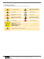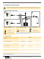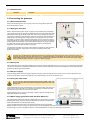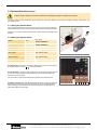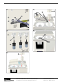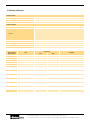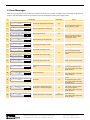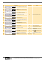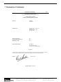
1
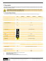
Hydrogen Gas Generator
H2PEM-100 / H2PEM-165 / H2PEM-260 / H2PEM-510
User Guide
EN
Original Language
aerospace
climate control
electromechanical
filtration
fluid & gas handling
hydraulics
pneumatics
process control
sealing & shielding
Warranty
This warranty applies to the generator and associated parts (the equipment) manufactured and supplied by Parker Hannifin Ltd.,
Industrial Division (the company).
Use of the generator without the recommended water quality or genuine parts will expressly invalidate the warranty.
It should be noted that the generator must be installed and running within three months of dispatch from the company to ensure
the optimum efficiency of the PEM cell. If this is not adhered to the warranty will be invalid. Should the equipment be defective as
to materials or workmanship, the company warrants that it will remedy such defect. Where the equipment is the generator, the
warranty period will be 12 months from date of commissioning or 18 months from date of manufacture, whichever comes first.
Where the equipment is the PEM CELL, the warranty period will be 24 months from date of commissioning. In the case of
equipment other than the generator, the warranty period shall commence from the date of dispatch.
Should any defect occur during the warranty period and be notified in writing to the company or its authorised distributor within
the said period, the company will, as its sole option, remedy such defect by repair or provision of a replacement part, provided
that the equipment has been used strictly in accordance with the instructions provided with each item of equipment and has been
stored, installed, commissioned, operated and maintained in accordance with such instruction and with good practice. The
company shall not be under any liability whatsoever under the warranty, if, before giving notification in writing to the company as
aforesaid, the Customer or any third party meddles, interferes, tampers with or carries out work whatsoever (apart from normal
maintenance as specified in the said instructions) in relation to the equipment or any part thereof.
Any accessories, parts and equipment supplied by the company but not manufactured by the company shall carry whatever
warranty the manufacturer has given the company providing it is possible for the company to pass on such warranty to the
customer.
To claim under the warranty, the goods must have been installed and continually maintained in the manner specified in the User
Guide. Our product support engineers are qualified and equipped to assist you in this respect. They are also available to make
repairs that may become necessary in which event they will require an official order before carrying out the work. If such work is
to be the subject of a warranty claim, the order should be endorsed for consideration under warranty.
Where equipment is sold outside the UK mainland direct to the end user the warranty will cover parts only. Any substitution of
parts not manufactured or approved by the company will expressly invalidate the warranty.
CONTENTS
1 Safety Information ........................................................................................................................................................................................1
1.1 Markings and Symbols ........................................................................................................................................................................2
2 Description ....................................................................................................................................................................................................3
2.1 Technical Specification........................................................................................................................................................................3
2.2 Approvals ..............................................................................................................................................................................................4
2.3 Materials of Construction ....................................................................................................................................................................4
2.4 Weight and Dimensions .......................................................................................................................................................................5
2.5 Receiving and Inspecting the Equipment ..........................................................................................................................................6
2.5.1 Storage.........................................................................................................................................................................................6
2.5.2 Unpacking ....................................................................................................................................................................................6
2.5.3 Overview of the equipment ..........................................................................................................................................................6
2.6 Locating the Equipment.......................................................................................................................................................................7
2.6.1 Environment .................................................................................................................................................................................7
2.6.2 Space Requirements....................................................................................................................................................................7
2.6.3 Ventilation Requirements .............................................................................................................................................................7
2.6.4 Water Supply Requirements ........................................................................................................................................................7
2.6.5 Electrical Supply Requirements ...................................................................................................................................................7
3 Installation & Commissioning .....................................................................................................................................................................8
3.1 Recommended system layout ............................................................................................................................................................8
3.1.1 Installation Parts...........................................................................................................................................................................8
3.1.2 Installation Kit ...............................................................................................................................................................................9
3.2 Connecting the generator....................................................................................................................................................................9
3.2.1 Environmental filters .....................................................................................................................................................................9
3.2.2 Hydrogen outlet port.....................................................................................................................................................................9
3.2.3 Drain ports....................................................................................................................................................................................9
3.2.4 Electrical supply ...........................................................................................................................................................................9
3.2.5 Filling the water bottle ..................................................................................................................................................................9
3.2.6 Water supply (generators fitted with Auto Water Fill) ...................................................................................................................9
3.3 Options Board Accessory .................................................................................................................................................................10
3.3.1 Fitting the Options Board............................................................................................................................................................10
3.3.2 Wiring the Options Board ...........................................................................................................................................................10
3.4 Commissioning the Generator .........................................................................................................................................................11
4 Operating the equipment ...........................................................................................................................................................................12
4.1 Overview of controls ..........................................................................................................................................................................12
4.2 Starting the equipment ......................................................................................................................................................................12
4.3 Operating Menus ................................................................................................................................................................................13
4.3.1 Default Menu ..............................................................................................................................................................................13
4.3.2 Conductivity................................................................................................................................................................................14
4.3.3 Pressure Measurement ..............................................................................................................................................................14
4.3.4 Run Time Data ...........................................................................................................................................................................14
4.3.5 Flow............................................................................................................................................................................................14
4.3.6 Error Log ....................................................................................................................................................................................14
4.3.7 Generator Self Test ....................................................................................................................................................................14
4.3.8 Network Node Number...............................................................................................................................................................15
4.3.9 Cell Hydration Sequence............................................................................................................................................................15
4.4 Hard Reset...........................................................................................................................................................................................15
4.5 Stopping the equipment and depressurising ..................................................................................................................................15
5 Servicing......................................................................................................................................................................................................16
5.1 Cleaning ..............................................................................................................................................................................................16
5.1.1 Service Intervals.........................................................................................................................................................................16
5.2 Service Kits ........................................................................................................................................................................................17
5.2.1 Recommended Service A - Required every 4000Hrs (6 months) .............................................................................................17
5.2.2 Recommended Service B - Required every 16000Hrs (24 months) .........................................................................................17
5.2.3 Recommended Service C - As required.....................................................................................................................................17
5.3 Consumable Replacement Procedures ............................................................................................................................................18
5.3.1 Draining the water bottle (A).......................................................................................................................................................18
5.3.2 Replacing the deioniser cartridge and 100 micron water filter (B) .............................................................................................18
5.3.3 Replacing the Environmental Filters (C).....................................................................................................................................18
5.3.4 Replacing the Desiccant Cartridge (D) .......................................................................................................................................18
5.3.5 Filling the water bottle (E) ..........................................................................................................................................................18
5.4 Service Record ...................................................................................................................................................................................20
6 Error Messages ...........................................................................................................................................................................................21
7 Declaration of Conformity .........................................................................................................................................................................23
Parker Hannifin Corporation
Filtration and Separation Division, 242 Neck Road, Haverhill, MA 01835
Tel: 978-858-0505 Fax: 978-556-7501 www.labgasgenerators.com
Parker Hannifin Corporation 2011
Printed in U.S.A. Bulletin 174970328
1 Safety Information
Do not operate this equipment until the safety information and instructions in this user guide have been read and understood by all
personnel concerned.
USER RESPONSIBILITY
FAILURE OR IMPROPER SELECTION OR IMPROPER USE OF THE PRODUCTS DESCRIBED HEREIN OR RELATED ITEMS CAN CAUSE
DEATH, PERSONAL INJURY AND PROPERTY DAMAGE.
This document and other information from Parker Hannifin Corporation, its subsidiaries and authorised distributors provide product or system
options for further investigation by users having technical expertise.
The user, through its own analysis and testing, is solely responsible for making the final selection of the system and components and assuring
that all performance, endurance, maintenance, safety and warning requirements of the application are met. The user must analyse all aspects
of the application, follow applicable industry standards, and follow the information concerning the product in the current product catalogue and in
any other materials provided from Parker or its subsidiaries or authorised distributors.
To the extent that Parker or its subsidiaries or authorised distributors provide component or system options based upon data or specifications
provided by the user, the user is responsible for determining that such data and specifications are suitable and sufficient for all applications and
reasonably foreseeable uses of the components or systems.
Only competent personnel trained, qualified, and approved by Parker Hannifin should perform installation, commissioning, service and repair
procedures.
This equipment is for indoor use only. Do not operate outdoors.
This equipment is not suitable for use in any Hazardous, Flammable, or Explosive environments. Hydrogen is a highly flammable gas. Keep the
generator away from excessive heat and naked flames.
With the exception of oxygen, any gas can cause asphyxiation in high enough concentrations. In most scenarios, however, because hydrogen
rises and disperses so rapidly, it is unlikely to be confined where asphyxiation might otherwise occur. Always ensure that the generator is
operated in a well ventilated area and all of the vent ports on the rear of the generator are kept clear and free from blockages.
Use of the equipment in a manner not specified within this user guide may result in an unplanned release of pressure, which may cause serious
personal injury or damage.
When handling, installing or operating this equipment, personnel must employ safe engineering practices and observe all related regulations,
health & safety procedures, and legal requirements for safety.
Ensure that the equipment is depressurised and electrically isolated, prior to carrying out any of the scheduled maintenance instructions
specified within this user guide.
Parker Hannifin can not anticipate every possible circumstance which may represent a potential hazard. The warnings in this manual cover the
most known potential hazards, but by definition can not be all-inclusive. If the user employs an operating procedure, item of equipment or a
method of working which is not specifically recommended by Parker Hannifin the user must ensure that the equipment will not be damaged or
become hazardous to persons or property.
Most accidents that occur during the operation and maintenance of machinery are the result of failure to observe basic safety rules and
procedures. Accidents can be avoided by recognising that any machinery is potentially hazardous.
Note: Any interference with the calibration warning labels will invalidate the gas generator's warranty and may incur costs for the recalibration of
the gas generator.
Should you require an extended warranty, tailored service contracts or training on this equipment, or any other equipment within the Parker
Hannifin range, please contact your local Parker Hannifin office.
Details of your nearest Parker Hannifin sales office can be found at www.parker.com/pag
Retain this user guide for future reference.
Parker Hannifin Corporation
Filtration and Separation Division, 242 Neck Road, Haverhill, MA 01835
Tel: 978-858-0505 Fax: 978-556-7501 www.labgasgenerators.com
1
Parker Hannifin Corporation 2011
Printed in U.S.A. Bulletin 174970328
1.1 Markings and Symbols
The following markings and international symbols are used on the equipment or within this manual:
DO NOT OBSTRUCT VENT PORTS
LEAVE OPEN TO ATMOSPHERE OR
PIPE TO VENTILATED AREA
WARNING
GENERATOR MUST BE SHUT DOWN AND
DEPRESSURISED BEFORE PERFORMING
ANY MAINTENANCE
(REFER TO USER GUIDE)
LISTED
Caution, Read the User manual.
Highlights actions or procedures which, if not
performed correctly, could lead to electric
shock.
Risk of electric shock.
When disposing of old parts always follow local
waste disposal regulations.
Highlights actions or procedures which, if not
performed correctly, may lead to personal
injury or death.
Conformité Européenne
Highlights actions or procedures which, if not
performed correctly, may lead to damage to
this product.
Waste electrical and electronic equipment
should not be disposed of with municipal
waste.
Wear disposable gloves.
Do not expose to naked flame.
DO NOT OBSTRUCT VENT PORTS LEAVE
OPEN TO ATMOSPHERS OR PIPE TO
VENTILATED AREA
WARNING
GENERATOR MUST BE SHUTDOWN AND
DEPRESSURIZED BEFORE
PERFORMING ANY MAINTENANCE
(REFER TO USER manual)
This product has been certified by Underwriters Laboratories®.
LABORATORY
EQUIPMENT 84NA
2
Parker Hannifin (UK) Ltd.
Suite 42, Industrial Division, Kent House, Romney Place, Maidstone Kent, ME15 6LH, UK
Tel: +44 (0) 1622 772440 Fax: +44 (0) 1622 772446 Email: [email protected] www.parker.com/pag
2 Description
This generator will produce a constant stream of high purity hydrogen at a predetermined flow rate and pressure when connected to a suitable
power supply and fed with a suitable quality of deionised water. It is suitable for use in laboratories and light industrial environments and is nonhazardous for transportation purposes.
In order to guarantee the optimum efficiency of the PEM cell, this generator must be installed and running within three months of dispatch
from Parker Hannifin. Failure to do this may invalidate the warranty.
The generator will perform a 240 minute (4 hours) initialisation sequence when powered for the first time. This sequence, which cannot be
aborted, is necessary to guarantee the correct hydration of the cell.
2.1 Technical Specification
This specification is valid when the equipment is located, installed, operated, and maintained as specified within this user guide.
Units
H2PEM-100
L/week
0.750
H2PEM-165
H2PEM-260
H2PEM-510
Water
Water quality
Deionised, ASTM II, >1 M, <1S, filtered to <100m
Consumption (Approximate)1
1.25
2
psi g
(bar g)
1.45
(0.1)
Supply flow rate (max) 2
cc/min
1000
Supply pressure (max)
o
F
(oC)
Supply temperature (max) 2
2
4
260
510
68
(20)
High Purity Hydrogen (H2)
Outlet flow rate
cc/min
Outlet pressure
psi g
(bar g)
5 -100 ± 0.5
(0.3 -6.89 ± 0.034)()
%
> 99.999%
Purity3
100
165
Mechanical Connections
Hydrogen outlet
18 Compression fitting
Water drain
Quick release push in fitting
Automatic water fill inlet (factory or field fit
option)
Blank
Overflow drain
Quick release push in fitting
Spillage drain
1/2” Barbed push on fitting
Electrical Data
Connection type
IEC320
Supply voltage range
Vac
Power consumption4
W
5
100-230 5060Hz
90
125
A
Fuse
185
235
5
Environmental Data
o
F
(oC)
41–104
(5–40)()
Relative Humidity
-
50% @ 104oF (40oC) (80% MAX < 87.8oF (31oC)
IP Rating
-
IP20, NEMA 1, indoor use only
Pollution Degree
-
2
Installation Over voltage Category
-
II
ft.
(m)
<6562
(2000)
dB(A)
< 60
Ambient Temperature
Maximum Altitude
Noise
1.
2.
3.
4.
5.
Based on full flow with 24 hour 7 day operation at 22oC (72oF) ambient temperature.
Applies to generators with auto water fill only.
The balance is O2 and moisture.
The power consumption when in standby mode is 20W.
Anti Surge (T), 250V, 5 x 20mm HBC, Breaking Capacity 1500A @ 250V, IEC 60127, UL R/C Fuse
Parker Hannifin Corporation
Filtration and Separation Division, 242 Neck Road, Haverhill, MA 01835
Tel: 978-858-0505 Fax: 978-556-7501 www.labgasgenerators.com
3
Parker Hannifin Corporation 2011
Printed in U.S.A. Bulletin 174970328
2.2 Approvals
Safety and Electromagnetic Compatibility (EMC)
This equipment has been tested and complies with the following European Standards:
EN61010-1: 2001 — Safety Requirements for Electrical Equipment for Measurement, Control, and Laboratory use - Part 1:
General Requirements.
EN61326: 2006 — Electrical Equipment for Measurement, Control, and Laboratory use, EMC Requirements.
EN50366: 2003 (+ A1: 2006) — Household and similar electrical appliances. Electromagnetic fields. Methods for evaluation and
measurement.
IEC 62233: 2008 — Measurement methods for electromagnetic fields of household appliances and similar apparatus with regard
to human exposure.
LISTED
This equipment has been tested to and complies with the following standard:
UL 61010-1 2nd Edition, “Electrical Equipment for Laboratory Use; Part 1: General Requirements.
CAN/CSA C22.2 No.61010-1 2nd Edition, “Electrical Equipment for Laboratory Use; Part 1: General Requirements.
LABORATORY
EQUIPMENT 84NA
2.3 Materials of Construction
Facia and Covers
Noryl FN150 (R4G334/ AE251/1 Trimite coated)
Chassis
Mild Steel (Epoxy Powder Coated)
Seal Materials
Nitrile, Viton, EPDM, PTFE (tape)
Display Bezel
PA-765 ABS
Display Facia
Polyester film (Lumirror S10)
Deionised Water Circuit Tubing
Tygon, Natural PTFE
Hydrogen Circuit Tubing
Natural PTFE
Inlet/ Outlet Circuit Tubing
Cleaned* Stainless Steel 316 (Inlet/ outlet Piping)
Satellite filter
Polypropylene
Barbed Fittings
Water Reservoir
Float
Polyethylene
Conductivity Sensor
Floats
Polyvinyl Chloride
Manifold, Bowl and Spigot
Natural Polycarbonate
JG Fittings
Acetyl
Conductivity Probes
Water Bottle to Pump Fitting
Clean 316 Stainless Steel
Pressure Switch
4
PEM Cell
Platinum and Titanium
Desiccant Cartridge (adsorbant)
Molecular Sieve MS 544/Clear Polycarbonate Cal. 300EP-22
Mounting Feet
Polyamide reinforced nylon and plated mild steel
Parker Hannifin (UK) Ltd.
Suite 42, Industrial Division, Kent House, Romney Place, Maidstone Kent, ME15 6LH, UK
Tel: +44 (0) 1622 772440 Fax: +44 (0) 1622 772446 Email: [email protected] www.parker.com/pag
2.4 Weight and Dimensions
The dimensions and weight of the equipment are specified below.
W
Dimension
Units
H2PEM-100
H2PEM-165
H2PEM-260
H2PEM-510
H
in (mm)
17.1
(435)
17.1
(435)
17.1
(435)
17.1
(435)
W
in (mm)
13.5
(342)
13.5
(342)
13.5
(342)
13.5
(342)
D
in (mm))
18
(457)
18
(457)
18
(457)
18
(457)
(a)
in (mm)
25.4
(645)
25.4
(645)
25.4
(645)
25.4
(645)
(b)
in (mm)
4.3
(108)
4.3
(108)
4.3
(108)
4.3
(108)
(c)
in (mm)
4.4
(111.5)
4.4
(111.5)
4.4
(111.5)
4.4
(111.5)
(d)
in (mm)
2.3
(59.5)
2.3
(59.5)
2.3
(59.5)
2.3
(59.5)
Water bottle empty
lb (Kg)
41.9 (19)
41.9 (19)
41.9 (19)
41.9 (19)
Water bottle full
lb (Kg)
50.7 (23)
50.7 (23)
50.7 (23)
50.7 (23)
(c)
(d)
(b)
H
(a)
D
Weight
Table 2.2 Weight and Dimensions
Parker Hannifin Corporation
Filtration and Separation Division, 242 Neck Road, Haverhill, MA 01835
Tel: 978-858-0505 Fax: 978-556-7501 www.labgasgenerators.com
5
Parker Hannifin Corporation 2011
Printed in U.S.A. Bulletin 174970328
2.5 Receiving and Inspecting the Equipment
On receipt of the equipment carefully inspect the packaging for damage. If the packaging is damaged inform the delivery company immediately
and contact your local Parker Hannifin office.
2.5.1 Storage
If the equipment is to be stored prior to installation, do not remove it from the packaging. Ensure that it is stored in an upright position as
indicated by the arrows on the packaging.
Do not attempt to lift the generator by yourself. It is recommended that the generator be carried by a minimum of two persons or transported
on a pallet truck.
Note. The storage area should be secure and the environmental conditions should fall within those specified in the technical specification.If the
generator is stored in an area where the environmental conditions fall outside of those specified, it is essential that it be moved to its final
location (installation site) and left to stabilise prior to unpacking. Failure to do this could cause condensing humidity and potential failure of the
generator.
2.5.2 Unpacking
Once ready to install, remove the equipment from the packaging and check for signs of damage. Verify that the following items have been
included with the shipment:
Description
Qty
Water drain tube
1
1
1
Water fill tube
Deioniser cartridge
1
Environmental filters
3
Electrical supply cable
3
1. Supplied only with generators fitted with the water fill option.
If any items are missing or damaged please contact your local Parker Hannifin office. Do not attempt to power up the generator.
2.5.3 Overview of the equipment
11
6
7
12
8
10
9
Key:
6
1
Control panel
7
Auto water fill connection (factory or field fit option)
2
Options board connection port
8
Overflow drain
3
O2 Vent (<250ml/min)
9
Fused IEC 320 inlet socket and ON/OFF switch
4
Excess H2 vent (<1ml/min)
10
Water bottle spillage drain
5
Water bottle vent
11
Environmental filter
6
Water drain
12
Hydrogen Outlet
Parker Hannifin (UK) Ltd.
Suite 42, Industrial Division, Kent House, Romney Place, Maidstone Kent, ME15 6LH, UK
Tel: +44 (0) 1622 772440 Fax: +44 (0) 1622 772446 Email: [email protected] www.parker.com/pag
2.6 Locating the Equipment
This equipment is not suitable for use in any Hazardous, Flammable, or Explosive environments. Keep the generator away from excessive
heat and naked flames.
2.6.1 Environment
The equipment should be located indoors in an environment that protects it from direct sunlight, moisture, and dust. Changes in temperature,
humidity, and airborne pollution will affect the environment in which the equipment is operating and consequently may impair the safety and
operation.
It is the customers' responsibility to ensure that the environmental conditions specified in table 2.1 are maintained.
2.6.2 Space Requirements
The equipment should be mounted on a flat surface, capable of withstanding the weight of the equipment and all ancillary parts. A minimum
clearance of 150mm (5.9in) should be provided on all sides of the generator for air flow. Additional space should be provided so that the
generator can be moved to allow unrestricted access to the generator during servicing and maintenance.
Do Not block the side vents or the fans located on the rear panel of the generator.
When considering the vertical clearance you must take into account the height required when the front upper access panel is in the open
position. Refer to table 2.2 for overall dimensions of the equipment.
Do Not position the equipment so that it is difficult to operate or disconnect from the electrical supply.
2.6.3 Ventilation Requirements
The accumulation of hydrogen can displace oxygen thereby creating and asphyxiation hazard. Always ensure that the equipment is operated
in a well ventilated area.
2.6.4 Water Supply Requirements
Generators fitted with automatic water fill system maintain the water level from a gravity fed fresh deionised water supply. Refer to “Technical
Specification” on page 3 for the supply requirements.
The use of any water, other than deionised water (Deionised, ASTM II, >1 M, <1S, filtered to <100m), within this generator will damage and
reduce the life time of the hydrogen cell.
The generator should be connected to the supply using 1/4” Tygon or PTFE tubing (not supplied).
Note. The automatic water fill system is available as a factory or field fit optional extra. Contact Parker Hannifin for further details.
2.6.5 Electrical Supply Requirements
The equipment should be connected directly from the fused IEC 320 inlet socket to the electrical supply using the power cord supplied. The
equipment should be positioned so that it can be connected to the electrical supply without the use of an extension cord.
It is the customers responsibility to provide a fused electrical supply to the equipment (Refer to table 2.1 for the electrical specification). It is
recommended that this supply have surge protection.
The equipment is connected to protective earth (ground) through the power cord. It is essential that electrical supply is equipped with a
protective earth (ground) terminal. If an alternative power cord is used to connect the equipment to the electrical supply, ensure that it is
suitably rated for the application and contains a protective earth (Ground) conductor.
Parker Hannifin Corporation
Filtration and Separation Division, 242 Neck Road, Haverhill, MA 01835
Tel: 978-858-0505 Fax: 978-556-7501 www.labgasgenerators.com
7
Parker Hannifin Corporation 2011
Printed in U.S.A. Bulletin 174970328
3 Installation & Commissioning
Only competent personnel trained, qualified, and approved by Parker Hannifin should perform commissioning and service procedures.
3.1 Recommended system layout
A
D
C
B
A
Single generator
C
Application Instrument
Non return valve
B
Multiple generators
D
Back up supply
Flow Controller
Pressure regulator
Pressure relief valve
Isolation Valve
3-way ball valve with vent
line.
Note. The pressure regulator and flow controller shown in (C) are recommended to account for pressure drop across
the piping. This may be integrated in to the application instrument.
3.1.1 Installation Parts.
Part Number
Description
Stainless Steel
Brass
Copper
1/8" OD Tube Ball Valve
2A-MB2LPFA-SSP
2A-MB2LPFA-BP
--
1/4" OD Tube Ball Valve
4A-MB4LPFA-SSP
4A-MB4LPFA-BP
--
1/8" OD Tube 3 Way Ball Valve
2A-MB2XPFA-SSP
2A-MB2XPFA-BP
--
1/4" OD Tube 3 Way Ball Valve
4A-MB4XPFA-SSP
4A-MB4XPFA-BP
--
VCD-SVS-1500
--
--
1/8" OD Tube Non Return Valve
2A-C2L-1-BN-SS
2A-C2L-1-BN-BP
--
1/4" OD Tube Non Return Valve
1/8" OD Tube Flow Controller (0-1200 ml/min)
4A-C4L-1-BN-SS
4A-C4L-1-BN-B
--
1/8" OD Tube Equal Tee
2ET2-316
2ET2-B
--
1/4" OD Tube Equal Tee
4ET4-316
4ET4-B
--
4-4-2 JLZ-SS
4-4-2 JLZ-B
--
1/4" OD Tube Tee with 1/8" Side Port
1/8" OD Tube Pressure Relief Valve
This relief valve should be sized by the installer to suit the installation
1/4" BSPP Pressure Regulator
IR4003SK3SP24B
1/8" BSPT (R1/8") to 1/8" OD Tube Connector
2MSC2K-316
2MSC2K-B
1/4" BSPT (R1/4") to 1/4" OD Tube Connector
4MSC4K-316
4MSC4K-B
---
1/8" OD Copper Tube (Grade B-280) (50 FT)
--
--
X50CT-2-30
1/4" OD Copper Tube (Grade B-280) (50 FT)
--
--
X50CT-4-30
Installation Parts display Parker Master Catalogue part number and may ordered through your local authorised Parker Sales Company. Please note gas bottle and/or gas bottle
regulator are not supplied by Parker Hannifin.
8
Parker Hannifin (UK) Ltd.
Suite 42, Industrial Division, Kent House, Romney Place, Maidstone Kent, ME15 6LH, UK
Tel: +44 (0) 1622 772440 Fax: +44 (0) 1622 772446 Email: [email protected] www.parker.com/pag
3.1.2 Installation Kit
Kit Number
Description
IK7532
Installation Kit including:
Copper tube (50 ft), 18 tube nuts (x3), Front and back ferrules (x3), 18 tube T-pieces (x1)
3.2 Connecting the generator
3.2.1 Environmental filters
Remove the transit plugs from the vent ports, on the rear of the generator, and fit the
environmental filters as shown.
3.2.2 Hydrogen outlet port
Refer to “Recommended system layout” on page 8 for the desired system configuration.
The generator should be connected to the application instrument using either high quality
stainless steel tube or grade (B-280) copper tube. Remove the protective dust cap from
the hydrogen outlet port compression fitting. Insert the tube into the outlet port fitting and
rotate the tube nut until finger tight. Using a spanner (wrench) tighten the nut one and
one-quarter (1 14) turns. When cutting the tubes always use the correct tools to allow a
clean perpendicular cut. Cutting tubes will cause debris that, if not removed, may damage
the downstream instrumentation. It is recommended that all pipes are purged to remove
any debris that may exist. When routing the tubes ensure that they are adequately
supported to prevent damage and leaks in the system.
All components used within the system must be rated to at least the maximum operating
pressure of the equipment. Always protect the system by installing suitably rated
pressure relief valves.
To prevent injury, and damage to the application instrument, the system piping will require purging for at least 15 minutes to remove any
trapped oxygen. If using a 3-way ball valve with vent line, as recommended on page 8, ensure that the valve is open to the vent line and not to
the application instrument. If a ball valve is not being used, ensure that the application instrument is not connected to the system piping.
Refer to “Commissioning the Generator” on page 11 for details on purging.
3.2.3 Drain ports
The overflow drain and the water bottle spillage drain must be permanently piped away using 1/2” and 1/4” Tygon or PTFE tubing respectively.
The tube connected to the overflow drain should have a u-bend to prevent contamination of the internal water bottle. Always check with local
guidelines for disposing of deionised water.
3.2.4 Electrical supply
Check the rating plate for the correct supply voltage and frequency. Select the required power cord and connect it to the switched IEC 320
socket on the generator. Connect the plug directly to the electrical supply. Do not use an extension cord.
3.2.5 Filling the water bottle
The use of any water, other than deionised water (Deionised, ASTM II, >1 M, <1S,
filtered to <100m), within this generator will damage and reduce the life time of the
hydrogen cell.
Fill the water bottle using fresh deionised water to a level approximately 15mm below the
upper lip of the neck of the bottle. If the generator is powered up an audible and visual
indication will be given when the correct level is reached.
Wearing suitable gloves to prevent contamination, insert the deioniser cartridge into the
water bottle and fit the cap securely.
3.2.6 Water supply (generators fitted with Auto Water Fill)
The optional water fill allows the generator's water bottle to be gravity fed from a suitable
deionised water supply. When the water level falls below the mid-point, the water bottle
will be replenished from the deionised water supply.
WA T E R
F U L L
Connect the deionised water supply to the automatic water fill inlet using the barbed
adaptor provided and clean 1/4” Tygon (or similar) tubing. It is recommended that a balance line is fitted at the inlet to prevent air locks. Flush
the line through to remove any trapped air. Refer to “Technical Specification” on page 3 for water supply requirements.
Parker Hannifin Corporation
Filtration and Separation Division, 242 Neck Road, Haverhill, MA 01835
Tel: 978-858-0505 Fax: 978-556-7501 www.labgasgenerators.com
9
Parker Hannifin Corporation 2011
Printed in U.S.A. Bulletin 174970328
3.3 Options Board Accessory
The options board is designed for connection to Safe Extra Low Voltage (SELV) systems only. Maximum 12vdc 50mA.
The options board accessory allows direct communication with a PC via the USB port, and connection of water monitoring, remote alarm, and
remote stop circuits.
3.3.1 Fitting the Options Board
Plug the options board into the 15-way D-type connector on the rear of the generator.
The board should be secured in place using the retaining screw and spacer provided.
Place the cover over the options board and secure in place using the 2 retaining screws
provided.
3.3.2 Wiring the Options Board
RS485
JP1_1
NOT USED
(DO NOT CONNECT)
RS485
JP2_1
NOT USED
(DO NOT CONNECT)
Remote Stop
JP3_1
Switched input
JP3_2
GND
Alarm Output
Water Fill Output
USB
JP4_1
JP4_2
JP5_1
JP5_2
Open collector output
Open collector output
JP6
JP3 Remote Stop–The remote stop function allows the generator to be connected to
an external stop circuit. Press
to reset the generator.
JP4 Alarm Output–The alarm output is designed for remote alarm indication. When an
error occurs on the generator, the output switching circuit is activated causing the
remote circuit to be complete.
The remote alarm circuit will be reset when the generator error has been reset.
JP3
JP4 JP5
1
1
2
2
1
JP5 Water Fill Output–The water fill output allows for remote monitoring of the water
bottle level. When the water level drops below the mid-point in the water bottle the
output switching circuit is activated. The circuit will only be de-energised when the
water bottle is filled to its upper limit.
10
Parker Hannifin (UK) Ltd.
Suite 42, Industrial Division, Kent House, Romney Place, Maidstone Kent, ME15 6LH, UK
Tel: +44 (0) 1622 772440 Fax: +44 (0) 1622 772446 Email: [email protected] www.parker.com/pag
2
3.4 Commissioning the Generator
Ensure that a suitable vent line is provided during the commissioning stage as hydrogen will flow from the unterminated system piping.
In order to guarantee the optimum efficiency of the PEM cell, this generator must be installed and running within three months of dispatch
from Parker Hannifin. Failure to do this may invalidate the warranty.
The generator will perform a 240 minute (4 hours) initialisation sequence when powered for the first time. This sequence, which cannot be
aborted, is necessary to guarantee the correct hydration of the cell.
1
Referring to the recommended set up, use the 3-way ball valve to isolate the application instrument from the system and divert the flow to
the vent line.
If a 3-way ball valve has not been installed, disconnect the application instrument from the system and connect the open ended piping to a
suitable vent line.
2
Connect the generator to the electrical supply and switch it on at the wall socket. Turn the
generator on at the power switch (located on the rear of the generator) and wait.
SE T
AC T
1 0 0 P S I
9 0 P S I
F L OWX
SE T
AC T
1 0 0 P S I
1 0 0 P S I
F L OW
The generator will perform a system check during which time the water bottle indicators will
illuminate blue then red, the system check LED will flash, and the software version number,
generator serial number and the company banner will be displayed on the LCD.
On completion the generator will revert to the default menu as shown.
Note: Upon first use the generator may appear to stop building pressure while the
separation chamber fills with water. Should this happen, restart the generator.
3
The internal pressure (“ACT” pressure) of the generator will build up to the required operating pressure (“SET” pressure).
4
Once the required pressure is reached, the outlet valve of the generator will be opened, as indicated by “ F L O W ” on the display, and
hydrogen will flow through the system piping and out through the atmospheric vent line.
Unless a high capacity moisture trap is fitted at the inlet to the application instrument, continue running in this state for up to 48 hours to
reach the required purity.Failure to do so could damage the application instrument.
5
Close the 3-way ball valve to pressurise the system piping. Check for leaks and repair as required.
6
Open the 3-way ball valve to divert the flow to the application instrument.
During start-up the generator may revert to the last error mode it experienced. If this occurs press
generator will continue with the start up procedure.
. When the error is cleared the
If the error cannot be cleared by this method follow the fault finding procedure in section 6 of this user guide.
If the pressure envelope of the system has been breached it will be necessary to run through this procedure when starting the generator.
Parker Hannifin Corporation
Filtration and Separation Division, 242 Neck Road, Haverhill, MA 01835
Tel: 978-858-0505 Fax: 978-556-7501 www.labgasgenerators.com
11
Parker Hannifin Corporation 2011
Printed in U.S.A. Bulletin 174970328
4 Operating the equipment
4.1 Overview of controls
1
16x2 line menus display.
2
Control key pad used for menu navigation and generator
operation.
3
Tri coloured System Check Indicator.
Indicator
Generator Status
Flashing Green -
Start Up
Initialisation
Solid Green -
On-line
Flashing Red -
Non Critical Errors
Red -
Critical Errors
(System Locked)
Amber -
On-line, Service Required
4.2 Starting the equipment
Connect the generator to electrical supply and switch it on at the wall socket. Turn the generator
on at the power switch (located on the rear of the generator) and wait.
SE T
AC T
1 0 0 P S I
9 0 P S I
F L OWX
SE T
AC T
1 0 0 P S I
1 0 0 P S I
F L OW
The generator will perform a system check during which time the water bottle indicators will
illuminate blue then red, the system check LED will flash, and the software version number,
generator serial number and the company banner will be displayed on the LCD.
On completion the generator will revert to the default menu as shown.
Note: Upon first use the generator may appear to stop building pressure while the separation
chamber fills with water. Should this happen, restart the generator.
The internal pressure (“ACT” pressure) of the generator will build up to the required operating
pressure (“SET” pressure). Once the required pressure is reached, the outlet valve of the generator will be opened, as indicated by
“ F L O W ” on the display, and hydrogen will be supplied to the application instrument.
If the generator is being powered for the first time, it will take approximately 48 hours for the generator to reach the purity specified.
During start-up the generator may revert to the last error mode it experienced. If this occurs press
generator will continue with the start up procedure.
. When the error is cleared the
If the error cannot be cleared by this method follow the fault finding procedure in section 6 of this user guide.
12
Parker Hannifin (UK) Ltd.
Suite 42, Industrial Division, Kent House, Romney Place, Maidstone Kent, ME15 6LH, UK
Tel: +44 (0) 1622 772440 Fax: +44 (0) 1622 772446 Email: [email protected] www.parker.com/pag
4.3 Operating Menus
There are 9 menus used by the generator to display and access operational parameters and data. These can be accessed from the default
menu by sequentially pressing
on the control panel.
SE T
AC T
1
1 0 0 P S I
1 0 0 P S I
F L OW
C ON D U C T I V I T Y
X
2
P R E S S U R E
P S I
4
H OU R S
R U N
S E R V I C E
I N
5
F L OW m l
L I T R E S
* *
7
S E T
8
Pressure - units of measurement
X X X X X
X X X X X
0 0 0
0 0 0
/ M I N
E R R OR
H OL D
6
S E L F
H OL D
Conductivity (water quality)
U OM
3
L OG
&
T E S T
&
N E T WO R K
H OL D
&
Run time / Service interval
Flow
Error Log
* *
NOD E
C E L L H Y D R A T I O N
&
H OL D
9
Default
Generator self test
Network node number
Cell hydration
4.3.1 Default Menu
The default menu displays the following data:
SET - The outlet pressure required by the application.
SE T
AC T
1 0 0 P S I
1 0 0 P S I
F L OW
The required outlet pressure can be adjusted up and down using the
and
keys respectively.
ACT - Current actual internal / outlet pressure of the generator.
FLOW X /
- Indicates the status of the generator outlet valve. “X” - Outlet is closed,
“ “- Outlet is open.
100% - The shaded blocks indicate the rate of hydrogen production.
Each block represents 20% of the rated capacity of the generator.
During initial start up, or after a massive pressure drop, all five blocks will be shaded
indicating that the generator is building up pressure and not currently on line. When
the generator is on-line and delivering gas to the application, the number of blocks shaded will depend upon the flow required by the
application.
Stand by Mode–The flow of hydrogen to the application can be interrupted by switching the generator into standby mode.
Press and hold
to select stand by. The default menu will change to the standby menu
as shown to indicate that the outlet valve is closed and hydrogen is no longer being supplied
to the application.
To return to normal operation, press
**
S T A N D B Y
1 0 0 P S I
**
**
R E S E T
**
AC T
.
Reset–Pressing the enter key (middle key) during an error condition will reset the system.
Parker Hannifin Corporation
Filtration and Separation Division, 242 Neck Road, Haverhill, MA 01835
Tel: 978-858-0505 Fax: 978-556-7501 www.labgasgenerators.com
13
Parker Hannifin Corporation 2011
Printed in U.S.A. Bulletin 174970328
4.3.2 Conductivity
The conductivity menu gives a graphical indication of the water quality. When all 10 blocks
are shaded the water quality is to specification.
C ON D U C T I V I T Y
X
When the number of shaded blocks drops to four, the “Change Water” error message will be
displayed, the water bottle indicator will flash red, and an intermittent alarm will sound.
Hydrogen will continue to be delivered to the application.
C h a n g e
Wa t e r
AC T
1 0 0 P S I
If the water quality degrades to the point at which none of the blocks are shaded, the outlet
valve of the generator will close and a conductivity error will be generated. The water bottle
indicator will illuminate red and a continuous alarm will sound. Hydrogen will not be delivered
to the application.
C o n d u c t i v i t y
AC T
1 0 0 P S I
Press
to advance to the next menu.
The water bottle should be drained and refilled with deionised water, ASTM II, >1 M, <1S, filtered to <100m at the earliest convenient time.
4.3.3 Pressure Measurement
The units of pressure measurement may be changed between bar, psi and Mpa.
Press
or
P R E S S U R E
P S I
to change the units of measurement.
When the desired units have been selected, press
U OM
to advance to the next menu.
4.3.4 Run Time Data
The Run Time Data Menu displays the following data:
H OU R S
R U N
I N
S E R V I C E
HOURS RUN - Time in hours that the generator has been producing hydrogen.
X X X X X
X X X X X
SERVICE IN - The time in hours that the generator can produce hydrogen before a
service is required.
4.3.5 Flow
The Flow menu displays the current flow and the total amount of hydrogen produced by the
generator when on-line.
F L OW m l
L I T R E S
/ M I N
0 0 0
0 0 0
Flow ml/min. - Current flow in ml/min being produced by the generator. This is for indication
only and we recommend the use of a flow meter to gain an accurate measurement.
Litres - Total amount of hydrogen produced by the generator measured in litres.
4.3.6 Error Log
The Error Log menu allows the user to access the 10 most recent error messages.
To access the errors press and hold
and
E R R OR
H OL D
.
The menu will display the most recent error, message number “0”, along with the date and
time of when the error occurred.
Use the
and
keys to scroll through the remaining error messages. Press
return to the error log menu.
L OG
&
D D / MM/ Y Y
H H : MM
*
D E S C R I P T I ON
0
*
to
4.3.7 Generator Self Test
The generator must be disconnected from the system when running the self test routine.
From the Self Test Menu press and hold
and
. As the generator runs through the test routine, the menus will change as follows:
Pressure release– All pressure within the generator is released. The test will not proceed
until the generator is fully depressurised.
Pressure build–The generator is pressurised to a maximum operating pressure of 6.89 bar g
(100 psi g). The time taken to reach this pressure is monitored by the generator.
14
P R E S S U R E
1 0 0 P S I
R E L E A S E
C A N C E L
P R E S S U R E
1 0 0 P S I
B U I L D
C A N C E L
Parker Hannifin (UK) Ltd.
Suite 42, Industrial Division, Kent House, Romney Place, Maidstone Kent, ME15 6LH, UK
Tel: +44 (0) 1622 772440 Fax: +44 (0) 1622 772446 Email: [email protected] www.parker.com/pag
Pressure Hold–The pressure is held for a predetermined time and the monitored for decay.
Pressure Release–The outlet solenoid valve opens to release all pressure within the
generator.
P R E S S U R E
1 0 0 P S I
H OL D
C A N C E L
P R E S S U R E
1 0 0 P S I
R E L E A S E
C A N C E L
Test Passed / Failed–Once fully depressurised the generator switches to standby and the
result of the test is displayed.
T E S T
P A S S E D
S T A N D B Y
NOTE Always perform a self test whenever the pressure circuit has been disturbed e.g. changing the desiccant
cartridge.
4.3.8 Network Node Number
S E T
Up to 27 generators can be networked together, and their status monitored remotely using
Parker Hannifin’s RemoteNet software. In order for the generator to be recognised on the
network it must be assigned a Node number (1-27). If the node number is set to zero the
generator will not appear on the network.
N E T WO R K
H OL D
&
NOD E
The Network Node number is set through the generator’s menu system as follows:
1
From the Set Network Node menu press and hold
2
Use the
3
Press
or
&
.
keys to select the required node number and press
.
twice to return to the default menu.
Note. Do not assign the same node numbers to different generators as this will cause communication errors.
Contact Parker Hannifin for further details on the RemoteNet software.
4.3.9 Cell Hydration Sequence
The cell hydration sequence should be run if the generator has not been powered up for 90 days or more.
From the default menu press
and hold both
and
seven times to navigate to the cell hydration menu. Press
to initiate the sequence.
The sequence takes approximately 240 minutes (4 hours) to complete, however it may be
aborted at any time by pressing
. On completion press
twice to return to the
default menu.
C E L L H Y D R A T I O N
H OL D
&
C E L L H Y D R A T I N G
X X X : X X
E X I T
4.4 Hard Reset
If a critical error occurs an error lock menu will be displayed and the generator will need to be hard reset. If an overpressure, H2 or O2 vent
blocked error occurs, the generator will need to be hard reset once the problem has been resolved. This will also be the case if the same error
is reset 3 times consecutively.
Before a hard reset is performed the initial fault must be rectified; refer to “Error Messages” on page 21 for guidance. When the faults are
rectified, switch the generator off at the mains switch.
Press and hold
. At the same time reapply the power to the generator. When the generator has powered up press
generator will reset all errors then continue with the normal start up procedure.
again. The
4.5 Stopping the equipment and depressurising
Ensure that the generator is fully depressurised prior to shipment or servicing.
1
Ensure that the application instrumentation no longer requires hydrogen.
2
Switch the generator off at the mains power switch and disconnect it from the electrical supply.
3
Slowly disconnect the Hydrogen outlet connection pipe from the side of the generator allowing the system to depressurise.
.
Hydrogen gas will escape under pressure when the piping is disconnected.
4
The generator is now shut down.
5
If the generator is to be transported drain the water from the generator as described in section 6. Refit the hydrogen outlet port cover and
the three transit plugs to the O2 vent, excess H2 vent and the water bottle vent.
Parker Hannifin Corporation
Filtration and Separation Division, 242 Neck Road, Haverhill, MA 01835
Tel: 978-858-0505 Fax: 978-556-7501 www.labgasgenerators.com
15
Parker Hannifin Corporation 2011
Printed in U.S.A. Bulletin 174970328
5 Servicing
The recommended service procedures identified below, along with all other repair and calibration work, should be undertaken by a Parker
Hannifin approved engineer.
5.1 Cleaning
Clean the equipment with a damp cloth only and avoid excessive moisture around any electrical sockets. If required you may use a mild
detergent, however do not use abrasives or solvents as they may damage the warning labels on the equipment.
Generator
Check for leaks.
Generator
Recommended Service A
6 Month Service.
Generator
Recommended Service B
24 Month Service.
Generator
Recommended Service C
Check the desiccant cartridge and replace if opaque.
Service
6Months
(4000Hrs.)
12Months
(8000Hrs.)
24Months
(16000Hrs.)
72 Months
(48000 Hrs.)
Check the water bottle spillage drains
66 Months
(44000 Hrs.)
Generator
60 Months
(40000 Hrs.)
Check the water conductivity.
54 Months
(36000 Hrs.)
Generator
36 Months
(24000 Hrs.)
Check the water level.
30 Months
(20000 Hrs.)
Generator
24 Months
(16000 Hrs.)
Check the STATUS / FAULT Indicator on the control panel.
18 Months
(12000 Hrs.)
Generator
12 Months
(8000 Hrs.)
Check the power ON indicator is illuminated.
6 Months
(4000 Hrs.)
Generator
48 Months
(32000 Hrs.)
Daily
Operation
42 Months
(28000 Hrs.)
Component
Weekly
5.1.1 Service Intervals
A
B
Key:
Check
Essential Procedure
servicereminder.com
Servicereminder.com is a web based reminder service developed to track when service work is due to be carried out. This ensures that parts can be ordered in
advance and that the service is carried out at the optimum time in accordance with the manufacturers recommendations. This service is free to use, simply log on
to www.servicereminder.com and select New User Registration.
16
Parker Hannifin (UK) Ltd.
Suite 42, Industrial Division, Kent House, Romney Place, Maidstone Kent, ME15 6LH, UK
Tel: +44 (0) 1622 772440 Fax: +44 (0) 1622 772446 Email: [email protected] www.parker.com/pag
5.2 Service Kits
5.2.1 Recommended Service A - Required every 4000Hrs (6 months)
Description
Filter Service
Catalogue Number
Technical Reference
MKH2PEM-6M
MKH2PEM-6M
Contents
(1) Deioniser cartridge
(2) 100 micron water filter
(3) Environmental filters (x3)
(4) Filter replacement tool
5.2.2 Recommended Service B - Required every 16000Hrs (24 months)
Description
Complete Service
Catalogue Number
Technical Reference
Contents
(1) Deioniser cartridge
(2) 100 micron water filter
(3) Environmental filters (x3)
(4) Filter replacement tool
(5) Float
(6) Water pump
(7) Desiccant cartridge
(8) Cartridge spanner (wrench)
(9) Service reset dongle
(10) 1/4” Tygon tube
MKH2PEM-24M
MKH2PEM-24M
Catalogue Number
Technical Reference
MKH2PEM-D
MKH2PEM-D
5.2.3 Recommended Service C - As required
Description
Replace Cartridge
Contents
(7) Desiccant cartridge
(8) Cartridge spanner
Note: The desiccant cartridge should be changed as and when required, however it is recommended that it is changed at least every 6, 4, and
2 months on the H2PEM-100 / H2PEM-165, H2PEM-260 and H2PEM-510 respectively.
Parker Hannifin Corporation
Filtration and Separation Division, 242 Neck Road, Haverhill, MA 01835
Tel: 978-858-0505 Fax: 978-556-7501 www.labgasgenerators.com
17
Parker Hannifin Corporation 2011
Printed in U.S.A. Bulletin 174970328
5.3 Consumable Replacement Procedures
5.3.1 Draining the water bottle (A)
Locate the drain port on the rear of the generator and insert the drain line (1). Ensure that the line is locked in position to obtain a complete seal.
Leave the water to drain into a suitable container, then press the lock (2) downwards and remove the line.
In order to prevent contamination and prolong the life of the cell do not reuse the old water.
5.3.2 Replacing the deioniser cartridge and 100 micron water filter (B)
Change the deioniser cartridge every 4000 hours (6 months), or if it has become contaminated.
Switch the generator into Stand by mode and remove the top front cover and the water bottle cap.
Wearing disposable gloves, remove the deioniser cartridge (3) and discard. Extract the 100 micron water filter (4) using the H2 filter replacement
tool (5). Push the tool over the filter so that the webs on the filter fit into the slots on the end of the tool. Unscrew the filter and remove it from the
water bottle.
Fit the replacement filter and ensure that it is secured into the water bottle. Refill the water bottle with deionised water, ASTM II, >1 M, <1S,
filtered to <100m, as described below, and fit the replacement deioniser cartridge.
Refit the water bottle cap and the top front cover and restart the generator.
5.3.3 Replacing the Environmental Filters (C)
Remove the three environmental filters (6) from the vent ports by pushing the push in fitting (7) upwards to release. Fit the replacement filters
and check that they are secure.
Note: Environmental filters should be changed every six months as there is no visual indication of exhausted filters.
5.3.4 Replacing the Desiccant Cartridge (D)
Depressurise the generator as specified in “Stopping the equipment and depressurising” on page 15.
Remove the top front cover. Break the seal of the cartridge using a sise 19mm open ended spanner (wrench) (8) and then unscrew it by hand.
Remove the cartridge and fit the replacement. The new cartridge should be tightened by hand and then nipped up, by a further 1/8th of a turn,
using the 19mm spanner (wrench).
Refit the top front cover and the outlet fitting. Restart the generator and initiate a self test as described in “Generator Self Test” on page 14.
5.3.5 Filling the water bottle (E)
The use of any water, other than deionised water (ASTM II, >1 M, <1S, filtered to <100m) within this generator will damage and reduce the
life time of the hydrogen cell.
Remove the top front cover and the water bottle cap (9). Fill the water bottle using fresh deionised water to a level approximately 15mm below
the upper lip of the neck of the bottle.
If the generator is powered during refilling, an audible and visual indication will be given by the generator when the correct level is reached, and
the LCD will display “Water Full” message. Once full replace the water bottle cap and top front cover.
Note: If the water has been changed due to high conductivity, the deioniser cartridge must also be changed.
18
Parker Hannifin (UK) Ltd.
Suite 42, Industrial Division, Kent House, Romney Place, Maidstone Kent, ME15 6LH, UK
Tel: +44 (0) 1622 772440 Fax: +44 (0) 1622 772446 Email: [email protected] www.parker.com/pag
A
B
C
D
E
Parker Hannifin Corporation
Filtration and Separation Division, 242 Neck Road, Haverhill, MA 01835
Tel: 978-858-0505 Fax: 978-556-7501 www.labgasgenerators.com
19
Parker Hannifin Corporation 2011
Printed in U.S.A. Bulletin 174970328
5.4 Service Record
Generator Details
Model Number:
Serial Number
Supply Voltage
Commissioned By:
Company Name
Address:
Telephone:
Fax:
Contact Name:
Date of Commission:
Service Interval
Months (Hours)
Serviced By
Date
Comments
Print
Sign
6 (4,000)
12 (8,000)
18 (12,000)
24 (16,000)
30 (20,000)
36 (24,000)
42 (28,000)
48 (32,000)
54 (36,000)
60 (40,000)
66 (44,000)
72 (48,000)
78 (52,000)
84 (56,000)
90 (60,000)
96 (64,000)
102 (68,000)
108 (72,000)
20
Parker Hannifin (UK) Ltd.
Suite 42, Industrial Division, Kent House, Romney Place, Maidstone Kent, ME15 6LH, UK
Tel: +44 (0) 1622 772440 Fax: +44 (0) 1622 772446 Email: [email protected] www.parker.com/pag
6 Error Messages
When an error occurs the LCD will cycle between the default menu and the error message. In addition to the error messages the generator will
provide a visual and audible indication using the System Check LED, Water Bottle Indicator and its integral sounder.
No.
1
Error Message
AC T
F i l l
Wa t e r
1 0 0 P S I
The water has dropped below the mid-point.
H2 Production
Action
Yes
Fill with deionised water, ASTM II, >1
M, <1S, filtered to <100m.
2
Wa t e r
Em p t y
AC T
1 0 0 P S I
Water has dropped below minimum point.
No
3
C h a n g e
Wa t e r
AC T
1 0 0 P S I
Water conductivity is high.
Yes
Drain the water bottle and refill with
deionised water, ASTM II, >1 M,
<1S, filtered to <100m.
4
C o n d u c t i v i t y
AC T
1 0 0 P S I
Water conductivity is unacceptably high.
5
V o l t a g e
H i g h
AC T
1 0 0 P S I
The hydrogen cell voltage is too high.
6
L o w
V o l t a g e
AC T
1 0 0 P S I
The hydrogen cell voltage is too low.
No
Contact Parker Hannifin for advice.
Reset / Hard reset the generator.
No
7
H i g h
C u r r e n t
AC T
1 0 0 P S I
The hydrogen cell current is too high.
8
L o w
C u r r e n t
AC T
1 0 0 P S I
The hydrogen cell current is too low.
If the problem persists contact Parker
Hannifin.
Contact your service agent for advice.
Check that the drying cartridge is fitted
correctly.
9
I n t e r n a l
AC T
1 0 0 P S I
L e a k
Hydrogen leak in the internal pressure
system.
No
Check the internal pressure circuit.
If the problem persists contact Parker
Hannifin for advice.
10
AC T
H 2
Ou t l e t
1 0 0 P S I
Check outlet piping and connections.
Massive pressure loss.
No
If the problem persists contact Parker
Hannifin for advice.
Check that the drying cartridge is fitted
correctly.
11
H y d r o g e n
AC T
1 0 0 P S I
L e a k
Internal leak.
No
Check the internal pressure circuit.
If the problem persists contact Parker
Hannifin for advice.
Check for external leaks on the outlet of
the generator.
12
AC T
Ov e r - R u n
1 0 0 P S I
The generator is operating above 100%
rated capacity or running to atmosphere.
No
Verify that the generator is specified
correctly for the application.
If the problem persists contact Parker
Hannifin for advice.
13
Ov e r
P r e s s u r e
AC T
1 0 0 P S I
Maximum internal pressure is exceeded.
Parker Hannifin Corporation
Filtration and Separation Division, 242 Neck Road, Haverhill, MA 01835
Tel: 978-858-0505 Fax: 978-556-7501 www.labgasgenerators.com
No
(System locked)
Depressurise the generator and
perform a hard reset.
If the problem persists contact Parker
Hannifin for advice.
21
Parker Hannifin Corporation 2011
Printed in U.S.A. Bulletin 174970328
No.
Error Message
14
C o n d u c t
T r a n s
1 0 0 P S I
AC T
There is a fault with the conductivity sensor.
15
P r e s s u r e
T r a n s
AC T
1 0 0 P S I
There is a fault with the pressure transducer
or wiring.
16
17
18
19
AC T
Wa t e r
P u mp
1 0 0 P S I
There is a fault with the water pump.
AC T
C a l i b r a t
1 0 0 P S I
The calibration file is out of date.
AC T
AC T
i o n
Wa t c h d o g
1 0 0 P S I
F L OA T
T R A N S
1 0 0 P S I
There is a fault in the float chamber; the
water level is too high.
21
S e r v i c e
R e q d
AC T
1 0 0 P S I
A service is required.
22
O2
V e n t
B l o c k e d
AC T
1 0 0 P S I
The oxygen vent is blocked.
24
22
AC T
R e m o t e
S t o p
1 0 0 P S I
L o c k
1 0 0 P S I
No
Contact Parker Hannifin for advice.
Yes
Perform the required service.
There is a fault with the float chamber water
level transducer.
F L OA T
C H A MB E R
1 0 0 P S I
AC T
AC T
Action
Internal software time out.
20
23
H2 Production
No
(System locked)
Remove the blockage and perform a
hard reset.
If the problem persists contact Parker
Hannifin for advice.
The terminals on JP3 of the options board
are short circuit.
No
Press
when required to reset
the generator.
Pressure error, O2 vent blocked or three
consecutive errors of the same type have
occurred.
No
(System locked)
Resolve the initial fault and reset the
generator.
Parker Hannifin (UK) Ltd.
Suite 42, Industrial Division, Kent House, Romney Place, Maidstone Kent, ME15 6LH, UK
Tel: +44 (0) 1622 772440 Fax: +44 (0) 1622 772446 Email: [email protected] www.parker.com/pag
7 Declaration of Conformity
Declaration of Conformity
EN
Parker Hannifin ltd, Industrial division
Dukesway, TVTE, Gateshead, Tyne & Wear, NE11 0PZ. UK
Laboratory Hydrogen Generator
H2PEM-100, H2PEM-165, H2PEM-260, H2PEM-510
Directives
2006/95/EC
2004/108/EC
Standards used
EN 61010-1 : 2001 + CORR 1 & 2
EN 61326 : 2006
EN 50366 : 2003 (A1 : 2006)
IEC 62233 : 2008
PED Assessment Route :
EC Type-examination Certificate:
Notified body for PED:
N/A
N/A
N/A
Authorised Representative
Derek Bankier
Divisional Quality Manager
Parker Hannifin Ltd, Industrial Division
Declaration
I declare that as the authorised representative, the above information in relation to the supply / manufacture of this product, is
in conformity with the standards and other related documents following the provisions of the above Directives.
Signature:
Date: 27/11/07
Declaration Number: 0045/271107
Parker Hannifin Corporation
Filtration and Separation Division, 242 Neck Road, Haverhill, MA 01835
Tel: 978-858-0505 Fax: 978-556-7501 www.labgasgenerators.com
23
Parker Hannifin Corporation 2011
Printed in U.S.A. Bulletin 174970328
L E
. R E
C
Y
A
B
L
.
. R
A B L E
E C Y C
L
E
R
E
C
L A
Y C
B
L
Parker Hannifin (UK) Ltd
Industrial Division, Suite 42, Kent House
Romney Place, Maidstone, Kent, ME15 6LH, UK
Tel: +44 (0) 1622 772440 Fax: +44 (0) 1622 772446
www.parker.com/pag
C
Parker Hannifin Corporation
Filtration and Separation Division
242 Neck Road, Haverhill, MA 01835
Tel: 978-858-0505 Fax: 978-556-7501
www.labgasgenerators.com
Copyright© Parker Hannifin Corporation 2001, 2011. All rights reserved.
Bulletin: 174970328 Rev: 05