1
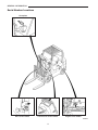
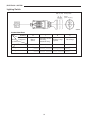
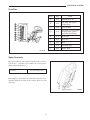
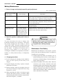
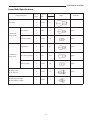
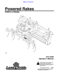
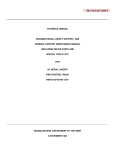
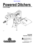
Service Manual
Chassis & Mast
GC15K
AT81C-00011-up
AT81D-00011-up
AT81E-00011-up
GC25K
AT82C-00011-up
AT82D-00011-up
AT82E-00011-up
GC18K
AT81C-00011-up
AT81D-00011-up
AT81E-00011-up
GC25K HP
AT82C-90011-up
AT82D-90011-up
AT82E-90011-up
GC20K
AT82C-00011-up
AT82D-00011-up
AT82E-00011-up
GC30K
AT83C-00011-up
AT83D-00011-up
AT83E-00011-up
GC20K HP
AT82C-90011-up
AT82D-90011-up
AT82E-90011-up
For use with 4G63/4G64 Engine Service Manual and
Liquefied Petroleum Gas Supplements.
99719-80150
FOREWORD
This service manual is a guide to servicing the 1-ton to 3-ton internal combustion cushion
models of CatTM Lift Trucks. The instructions are grouped by systems to serve the convenience
of your ready reference.
Long productive life of your lift trucks depends to a great extent on correct servicing – the
servicing consistent with what you will learn from this service manual. We hope you read the
respective sections of this manual carefully and know all the components you will work on
before attempting to start a test, repair or rebuild job.
For the items pertaining to the engines, refer to the following service manuals:
• 4G63/4G64 Gasoline Engine Service Manual (Pub. No. 99729-74120)
For use with both gasoline and LP Gas engines.
• 4G63/4G64 LP Gas Supplement (Pub. No. 99729-85100)
For use with LP Gas units with a “D” in the chassis serial number.
• 4G63/4G64 LP Gas Supplement (Pub. No. 99729-85110)
For use with LP Gas units with an “E” in the chassis serial number.
Safety Related Signs
The following safety related signs are used in this service
manual to emphasize important and critical instructions:
WARNING
CAUTION
NOTE
Indicates a specific potential hazard
resulting in serious bodily injury or
death.
Indicates a specific potential hazard
resulting in bodily injury, or damage
to, or destruction of, the machine.
Indicates a condition that can cause
damage to, or shorten service life of,
the machine.
Pub. No. 99719-80150
HOW TO READ THIS MANUAL
Disassembly diagram (example)
Each disassembly diagram is followed by
Disassembly sequence and Suggestions for
disassembly.
Disassembly sequence
Sequence
1. Cover, Bolt, Washer (part name)
2. Output shaft (part name)
Suggestion for disassembly
(1) Output shaft removal
Unit: mm (in.)
A
0.020 to 0.105
(0.00079 to 0.00413)
B
0.15
(0.0059)
Clearance between
cylinder and piston
A: Standard value
Symbols or abbreviations
OP ...................Option
R1/4.................Taper pipe thread (external) 1/4 inch (formerly PT1/4)
Rc1/8 ...............Taper pipe thread (internal) 1/8 inch (formerly PT1/8)
G1/4A..............Straight pipe thread (external) 1/4 inch (formerly PF1/4-A)
Rp1/8...............Straight pipe thread (internal) 1/8 inch (formerly PS1/8)
B: Repair or service limit
WARNING
SAFETY
WARNING
The proper and safe lubrication and
maintenance for this lift truck, recommended
by Cat, are outlined in the OPERATION &
MAINTENANCE MANUAL for these trucks.
Improper performance of lubrication or
maintenance procedures is dangerous and
could result in injury or death. Read and
understand
the
OPERATION
&
MAINTENANCE MANUAL before performing
any lubrication or maintenance.
The serviceman or mechanic may be unfamiliar with
many of the systems on this truck. This makes it
important to use caution when performing service
work. A knowledge of the system and/or components
is important before the removal or disassembly of any
component.
Because of the size of some of the truck components,
the serviceman or mechanic should check the weights
noted in this Manual. Use proper lifting procedures
when removing any components.
Following is a list of basic precautions that should
always be observed.
1. Read and understand all warning plates and decals
on the truck before operating, lubricating or
repairing the product.
2. Always wear protective glasses and protective
shoes when working around trucks. In particular,
wear protective glasses when pounding on any
part of the truck or its attachments with a hammer
or sledge. Use welders gloves, hood/goggles,
apron and other protective clothing appropriate to
the welding job being performed. Do not wear
loose-fitting or torn clothing. Remove all rings
from fingers when working on machinery.
3. Do not work on any truck that is supported only
by lift jacks or a hoist. Always use blocks or jack
stands to support the truck before performing any
disassembly.
WARNING
Do not operate this truck unless you have
read and understand the instructions in the
OPERATION & MAINTENANCE MANUAL.
Improper truck operation is dangerous and
could result in injury or death.
4. Lower the forks or other implements to the ground
before performing any work on the truck. If this
cannot be done, make sure the forks or other
implements are blocked correctly to prevent them
from dropping unexpectedly.
5. Use steps and grab handles (if applicable) when
mounting or dismounting a truck. Clean any mud
or debris from steps, walkways or work platforms
before using. Always face truck when using steps,
ladders and walkways. When it is not possible to
use the designed access system, provide ladders,
scaffolds, or work platforms to perform safe repair
operations.
6. To avoid back injury, use a hoist when lifting
components which weigh 23 kg (50 lb.) or more.
Make sure all chains, hooks, slings, etc., are in
good condition and are of the correct capacity. Be
sure hooks are positioned correctly. Lifting eyes
are not to be side loaded during a lifting
operation.
7. To avoid burns, be alert for hot parts on trucks
which have just been stopped and hot fluids in
lines, tubes and compartments.
8. Be careful when removing cover plates.
Gradually back off the last two bolts or nuts
located at opposite ends of the cover or device and
pry cover loose to relieve any spring or other
pressure, before removing the last two bolts or
nuts completely.
9. Be careful when removing filler caps, breathers
and plugs on the truck. Hold a rag over the cap or
plug to prevent being sprayed or splashed by
liquids under pressure. The danger is even greater
if the truck has just been stopped because fluids
can be hot.
10. Always use tools that are in good condition and
be sure you understand how to use them before
performing any service work.
11. Reinstall all fasteners with same part number.
Do not use a lesser quality fastener if
replacements are necessary. Do not mix metric
fasteners with standard nuts and bolts.
12. If possible, make all repairs with the truck
parked on a level, hard surface. Block truck so it
does not roll while working on or under truck.
13. Disconnect battery and discharge any capacitors
(electric trucks) before starting to work on truck.
Hang “Do not Operate” tag in the Operator’s
Compartment.
14. Repairs, which require welding, should be
performed only with the benefit of the
appropriate reference information and by
personnel adequately trained and knowledgeable
in welding procedures. Determine type of metal
being welded and select correct welding
procedure and electrodes, rods or wire to provide
a weld metal strength equivalent at least to that
of parent metal.
15. Do not damage wiring during removal
operations. Reinstall the wiring so it is not
damaged nor will it be damaged in operation by
contacting sharp corners, or by rubbing against
some object or hot surface. Do not connect
wiring to a line containing fluid.
16. Be sure all protective devices including guards
and shields are properly installed and functioning
correctly before starting a repair. If a guard or
shield must be removed to perform the repair
work, use extra caution.
17. Always support the mast and carriage to keep
carriage or attachments raised when maintenance
or repair work is performed, which requires the
mast in the raised position.
18. Loose or damaged fuel, lubricant and hydraulic
lines, tubes and hoses can cause fires. Do not
bend or strike high pressure lines or install ones
which have been bent or damaged. Inspect lines,
tubes and hoses carefully. Do not check for
leaks with your hands. Pin hole (very small)
leaks can result in a high velocity oil stream that
will be invisible close to the hose. This oil can
penetrate the skin and cause personal injury. Use
cardboard or paper to locate pin hole leaks.
19. Tighten connections to the correct torque. Make
sure that all heat shields, clamps and guards are
installed correctly to avoid excessive heat,
vibration or rubbing against other parts during
operation. Shields that protect against oil spray
onto hot exhaust components in event of a line,
tube or seal failure, must be installed correctly.
20. Relieve all pressure in air, oil or water systems
before any lines, fittings or related items are
disconnected or removed. Always make sure all
raised components are blocked correctly and be
alert for possible pressure when disconnecting
any device from a system that utilizes pressure.
21. Do not operate a truck if any rotating part is
damaged or contacts any other part during
operation. Any high speed rotating component
that has been damaged or altered should be
checked for balance before reusing.
GENERAL INFORMATION
Vehicle Exterior
102696
Models
Truck model
Model code – Serial number
GC15K
AT81C – 00011- up
AT81D – 00011- up
AT81E – 00011- up
GC18K
AT81C – 00011- up
AT81D – 00011- up
AT81E – 00011- up
GC20K
AT82C – 00011- up
AT82D – 00011- up
AT82E – 00011- up
GC25K
AT82C – 00011- up
AT82D – 00011- up
AT82E – 00011- up
GC20K HO
AT82C – 90011- up
AT82D – 90011- up
AT82E – 90011- up
GC25K HO
AT82C – 90011- up
AT82C – 90011- up
AT82C – 90011- up
GC30K
AT83C – 00011- up
AT83C – 00011- up
AT83C – 00011- up
1-1
Engine mounted
Mitsubishi 4G63 gasoline engine
Mitsubishi 4G64 gasoline engine
GENERAL INFORMATION
Serial Number Locations
Nameplate
Mast serial number
Transmission serial number
Engine serial number
207070
1-2
GENERAL INFORMATION
Dimensions
G
C
L
K
D
E
J
A
H
I
P
B
M
N
O
F
207071
1-4
GENERAL INFORMATION
Unit: mm (in.)
Ref.
No.
Truck Model
Item
A
Maximum fork height
B
1-ton models
GC15K
GC18K
2-ton models
GC20K
GC20K HP
GC25K
GC25K HP
3-ton models
GC30K
3325 (131)
3340 (131)
3315 (130)
Free fork height
115 (4.5)
130 (5.1)
135 (5.3)
C
Fork spacing (out-to-out)
minimum/maximum
200/820
(8.0/32.3)
200/920
(8.0/36.2)
200/960
(10/38)
D
Fork length
E
Tilt angle (forward–backward)
F
Overall length
G
Overall width (outside of tires)
945 (37.5)
1055 (41.5)
1105 (43.5)
H
Overall height
(to top of mast lowered)
2105 (83)
2110 (83.5)
2155 (85)
I
Overall height
(to top of overhead guard)
2022 (79.6)
J
Overall height
(to top of mast extended)
4550 (179)
4565 (180)
4535 (176)
K
Trend (front)
793 (31.2)
877 (34.5)
902 (35.5)
L
Trend (rear)
826 (32.5)
M
Wheelbase
1190 (46.9)
1350 (53.1)
1500 (59.1)
N
Load moment constant
376 (14.8)
399 (15.7)
412 (16.2)
O
Rear overhang
P
Ground clearance (at frame)
1067 (42)
5–10°
2055 (80.9)
479 (18.9)
5–10°
2083 (82.0)
507 (20.0)
95 (3.7)
1-5
2227 (87.5)
5–6°
2287 (90)
2455 (96.7)
2060 (81.1)
922 (36.3)
475 (18.7)
897 (35.5)
532 (20.9)
130 (5.1)
897 (35.5)
529 (20.8)
GENERAL INFORMATION
Technical Data (Standard Models)
Truck Model
Item
Rated capacity/load center
kg/mm (lb/in.)
Work
performance
GC15K
GC18K
GC20K
GC25K
GC30K
1500/500
(3000/24)
1800/500
(3500/24)
200/500
(4000/24)
2500/500
(5000/24)
3000/500
(6000/24)
Maximum fork height
mm (in.)
3300 (131)
3300 (131)
3300 (131)
Lift speed (rated load)
mm/sec (fpm)
590 (116)
510 (100)
470 (93)
610 (120)
550 (108)
500 (98)
Lowering speed (rated load)
mm/sec (fpm)
Tilt angle (forward – backward)
Free fork height
Traveling
performance
mm (in.)
Forward
Travel speed (loaded)
km/h (mph) Reverse
Minimum turning radius
mm (in.)
Gradeability (rated load)
[at 1.6 km/h (1 mph)]
% tan
Overall length
mm (in.)
Overall width
mm (in.)
To top of
mast lowered
Overall height
To top of
mm (in.) mast extended
To top of
overhead guard
Dimensions
Wheel base
Tread
mm (in.)
mm (in.)
5–10°
5–10°
5–6°
115 (4.5)
130 (5.1)
135 (5.3)
15 (9.3)
16 (9.9)
16 (9.9)
15 (9.3)
16 (9.9)
1790 (70.4)
1945 (76.6)
2002 (78.8)
2169 (85.4)
35
31
25.5
21
23
2949 (116.1)
2980 (117.3)
4335 (170.7)
4392 (172.9)
4559 (179.5)
945 (37.2)
1055 (41.5)
1105 (43.5)
2105 (83)
2110 (83.1)
2155 (85)
4550 (179)
4565 (180)
4535 (176)
2022 (79.6)
2060 (81.1)
2060 (81.1)
1500 (59.1)
1190 (46.9)
1350 (53.1)
Front
793 (31.2)
877 (34.5)
Rear
826 (32.5)
Load moment constant
mm (in.)
Rear overhang
mm (in.)
Ground clearance (at frame)
16 (9.9)
1760 (69.3)
376 (14.8)
479 (18.9)
507 (20.0)
922 (36.3)
897 (35.5)
399 (15.7)
475 (18.7)
532 (20.9)
902 (35.5)
897 (35.5)
412 (16.2)
529 (20.8)
95 (3.7)
130 (5.1)
130 (5.1)
18 × 6 × 12-1/8
21 × 7 × 15
21 × 8 × 15
14 × 4-1/2 × 8
16 × 6 × 10-1/2
16 × 6 × 10-1/2
2630 (5800)
3650 (8050)
4170 (9190)
4G63
4G63
4G64
Make
Mitsubishi
Motors
Mitsubishi
Motors
Mitsubishi
Motors
Type
Gasoline
Gasoline
Gasoline
Tire size
mm (in.)
Front
Rear
Service weight (empty)
kg (lb)
Engine model
Cooling System
No. of cylinders - arrangement
Water
Water
Water
4 -in-line
4 -in-line
4 -in-line
4
4
4
No. of strokes
Types of combustion chambers
Semi-spherical
Semi-spherical
Semispherical
Valve arrangement
Overhead valve
and OHC
Overhead valve
and OHC
Overhead
valve and
OHC
Type of cylinder liners
Integral with
cylinder block
Integral with
cylinder block
Integral with
cylinder
block
85 × 88 (3.346 × 3.465)
85 × 88 (3.346 × 3.465)
86.5 × 100
(3.406 × 3.937)
1997 (121.8)
1997 (121.8)
2350 (143.4)
Engine
Cylinder bore × stroke
Displacement
mm (in.)
cc (cu in.)
1-6
GENERAL INFORMATION
Truck Model
Item
Compression ratio
8.6 : 1
57/2400
139 (14.2)
[105]/1600
139 (14.2)
[105]/1600
176 (18)
[130]/1600
576 × 604.6 × 730.7
(22.7 × 23.8 × 28.8)
576 × 604.6 × 730.7
(22.7 × 23.8 × 28.8)
576 × 604.6 × 736.7
(22.7 × 23.8 × 29.0)
150 (330)
150 (330)
150 (330)
Rear
Rear
Rear
Open BTDC
12°
12°
12°
Close ABDC
40°
40°
40°
Open BBDC
54°
54°
54°
Close ATDC
6°
6°
6°
Intake valves
0.00 (hot)
0.00 (hot)
0.00 (hot)
0.00 (hot)
0.00 (hot)
0.00 (hot)
Dimensions
(length × width × height)
mm (in.)
Weight (service)
kg (lb)
Location
mm Exhaust valves
Ignition
Firing order
Ignition timing BTDC
Fuel tank rated capacity
Spark
Spark
Spark
1-3-4-2
1-3-4-2
1-3-4-2
degree/rpm
liter (U.S. gal.)
4/700 ± 50 (gasoline)
9/700 ± 50 (LPG)
34 (9)
46 (12)
56 (15)
Type
With external resistor
With external resistor
With external
resistor
Make
Mitsubishi Electric
Mitsubishi Electric
Mitsubishi
Electric
Type
Non-contact point
type (C.E.I.)
Non-contact point
type (C.E.I.)
Non-contact
point type
(C.E.I.)
Make
Mitsubishi Electric
Mitsubishi Electric
Mitsubishi
Electric
Centrifugal
pneumatic type
Centrifugal
pneumatic type
Centrifugal
pneumatic type
W14EX-U
W14EX-U
W14EX-U
Ignition coil
Ignition
system
(gasoline
models)
Distributor
Spark advancer
Type
Spark plugs
Make
Denso
Denso
Denso
Size
mm (in.)
14 × 1.25
(0.55 × 0.049)
14 × 1.25
(0.55 × 0.049)
14 × 1.25
(0.55 × 0.049)
mm (in.)
0.7 to 0.8
(0.028 to 0.031)
0.7 to 0.8
(0.028 to 0.031)
0.7 to 0.8
(0.028 to 0.031)
Gap
Carburetor
Governor
Fuel system
Fuel pump
Air cleaner
Type
Down-draft
Down-draft
Down-draft
Make
Mikuni Kogyo
Mikuni Kogyo
Mikuni Kogyo
Type
Pneumatic
Pneumatic
Pneumatic
Make
Mikuni Kogyo
Mikuni Kogyo
Mikuni Kogyo
Type
Diaphragm
Diaphragm
Diaphragm
Make
Kyosan Electric
Kyosan Electric
Kyosan Electric
Type × number
Cyclone-paper
element × 1
Cyclone-paper
element × 1
Cyclone-paper
element × 1
Make
Nippon Rokaki
Nippon Rokaki
Nippon Rokaki
Pressure feed
Pressure feed
Pressure feed
Gear type
Gear type
Gear type
Paper-element type
Paper-element
type
Type
Oil pump
Lubrication
system
GC30K
8.5 : 1
N·m (kgf·m) [lbf·ft]/rpm
Valve clearance
GC25K
46/2400
Maximum torque
Exhaust valves
GC20K
8.5 : 1
Hp/rpm
Intake valves
GC18K
46/2400
Rated output
Engine
GC15K
Oil filter
Oil pan
Refill capacities
Oil filter
liter (U.S. gal.)
Total
Paper-element type
45 (1.2)
45 (1.2)
45 (1.2)
0.3 (0.1)
0.3 (0.1)
0.3 (0.1)
4.8 (1.3)
4.8 (1.3)
4.8 (1.3)
1-7
GENERAL INFORMATION
Truck Model
GC15K
Item
Type
Cooling
system
Radiator
Refill capacity
liter (U.S. gal.)
Water pump
Thermostat
Battery
Alternator
and regulator
Starter
Power train
Powershaft
transmission
Reduction gear
Differential
9.85 (2.6)
9.85 (2.6)
9.85 (2.6)
Centrifugal type
Centrifugal type
Centrifugal type
12
40
3-phase
3-phase
3-phase
V - kW
Type
Model
12 - 65
12 - 65
12 - 65
Built-in IC type
Built-in IC type
Built-in IC type
Lever-shift type
Lever-shift type
Lever-shift type
12 - 1.2
12 - 1.2
12 - 1.2
3-element, 1-stage,
2-phase
3-element, 1-stage,
2-phase
3-element,
1-stage, 2-phase
Daikin DC6649
Daikin XT027
Daikin DC6649
Stall torque ratio
2.8
3.0
3.0
Control and shift
Hydraulic column
shift
Hydraulic column
shift
Hydraulic
column shift
Forward
2.913
2.913
2.913
Reverse
2.913
2.913
2.913
Skew bevel
Ratios
Type of gears
Skew bevel
Skew bevel
Ratio
4.571
4.571
4.571
Axle housing
Banjo
Banjo
Banjo
Straight bevel - 2
Straight bevel - 2
straight bevel - 2
Straight bevel - 2
Straight bevel - 2
Straight bevel - 2
Full hydrostatic
power stearing
Full hydrostatic
power stearing
Full hydrostatic
power stearing
Type of gears- Gears
number
Pinions
Inside
83°
83°
78°05´
Outside
54°
56°
52°14´
330 (13)
330 (13)
330 (13)
mm (in.)
mm (in.)
63.5 × 40 (2.5 × 1.575)
76.2 × 50 (3.0 × 1.97)
195 (7.68)
210 (8.27)
Relief pressure
kPa (kgf/cm2) [psi]
7845 (80) [1138]
Flow rate
liter (U.S. gal.)/min
23 (6.07)
Rear axle
Front wheels
Rear wheels
Toe-in
Wheel
alignment
Corrugated fin
(pressure) type
40
Front axle
Traveling
system
Corrugated fin
(pressure) type
32
Effective stroke
Mounting
Corrugated fin
(pressure) type
Ah
Steering cylinder
ID × rod OD mm (in.)
Steering
cylinder
Forced
circulation
Wax type
V-A
Steering wheel diameter
Steering
system
Forced circulation
12
Type
Turning angle
Forced circulation
Wax type
Type
Torque
converter
GC30K
12
Regulator
Voltage - output
GC25K
Wax type
Alternator type
Capacity
GC20K
V
Voltage
5-hr rating
GC18K
Full-floating tubular
type
Full-floating tubular
type
Full-floating
tubular type
Elliott type
Elliott type
Elliott type
Fixed type
Fixed type
Fixed type
Center-pivot type
Center-pivot
type
Center-pivot type
mm (in.)
Camber
0
0
0
1°
1°
1°
Caster
0°
0°
0°
Kingpin inclination
0°
0°
0°
1-8
GENERAL INFORMATION
Truck Model
Item
Brake system
Parking brake
GC18K
Drum diameter
mm (in.)
254 (10.00)
310 (12.20)
310 (12.20)
Lining (length ×
width × thickness
× number)
mm (in.)
274.2 × 48.5 × 4.78 × 2
(10.80 × 1.91 × 0.19 × 2)
344 × 60.0 × 6.4 × 2
(13.54 × 2.36 × 0.24 × 2)
344 × 60.0 × 6.4 × 2
(13.54 × 2.36 ×
0.24 × 2)
Master cylinder
ID
mm (in.)
22.22 (0.8748)
22.22 (0.8748)
22.22 (0.8748)
Wheel cylinder
ID
mm (in.)
22.22 (0.8748)
28.58 (1.1252)
28.58 (1.1252)
Mechanical, mounted
on front wheels
Mechanical, mounted
on front wheels
Mechanical,
mounted
on front wheels
Unitized type
Unitized type
Unitized type
Gear
Gear
Gear
Shimadzu SGP1-27
Shimadzu SGP1-30
Shimadzu
SGP1-34
64.8 (3954)
/2400 rpm
72.0 (4394)
/2400 rpm
79.9 (4876)
/2400 rpm
Universal joint
Universal joint
Type
Model
Rated output
liter (cu in.)
Drive line
Universal joint
Model
Shimadzu MSV 04-3-7645
Relief pressure
kPa
(kgf/cm2) [psi]
Hydraulic
system
Type
Flow regulator
valve
Lift cylinders
Tilt cylinders
Regulated flow
rate
liter (cu in.)/min
ID
mm (in.) Stroke
ID
mm (in.) Stroke
Hydraulic tank capacity (approx.)
liter (U.S. gal)
Mast
Outer
Mast dimensions
mm (in.)
(Flange inside width ×
Flange × thk (F.R)×Flange Inner
thk (R.E) × Web thk)
mm (in.)
Type
Main rollers
Mast and
forks
GC30K
Self-adjusting
duo-servo
Body-frame
Control valve
GC25K
Self-adjusting
duo-servo
Type
Hydraulic pump
GC20K
Self-adjusting
duo-servo
Type
Service brake
GC15K
18142
+490
0
[2361
+5
(185 0 )
+71
0
]
+490
0
[2361
+490
18142 0
+5
(185 0 )
+71
[2361 0 ]
+5
(185 0 )
+71
0
]
Variable
Variable
Variable
50 ± 3 (3051 ± 183)
65 ± 3 (3967 ± 183)
75 ± 3
(4577 ± 183)
45 (1.77)
50 (1.97)
55 (2.17)
1650 (64.96)
1650 (64.96)
1600 (62.99)
63 (2.48)
70 (2.76)
80 (3.15)
96 (3.78)
111 (4.37)
111 (4.37)
21 (5.5)
30 (7.9)
36 (9.5)
Roller type CL
Roller type CL
Roller type CL
100 × 17 × 19 × 11
(3.94 × 0.67 × 0.75 × 0.43)
115 × 22 × 27 × 12
(4.53 × 0.87 × 1.06 × 0.47)
100 × 17 × 19 × 10
(3.94 × 0.67 × 0.75 × 0.39)
115 × 22 × 23 × 11
(4.53 × 0.87 × 0.91 × 0.43)
#6308 ball bearing
Diam × width
mm (in.)
18142
100 × 27 (3.94 × 1.06)
#6309 ball
bearing
#6309 ball bearing
115 × 30 (4.53 × 1.18)
Type
Lubricating type
needle roller bearing
Lubricating type
needle roller bearing
Lubricating type
needle roller
bearing
Diam × width
mm (in)
42 × 36 (1.65 × 1.42)
42 × 36 (1.65 × 1.42)
42×36
(1.65 × 1.42)
Side rollers
Lift chains
BL534
BL634
BL834
mm (in.)
1067 × 100 × 35
(42 × 4 × 1.4)
1067 × 100 × 40
(42 × 4 × 1.6)
1067 × 125 × 45
(42 × 5 × 1.8)
mm (in.)
200 to 820
(8 to 32.5)
200 to 920
(8 to 36)
200 to 960
(10 to 38)
Fork (length × width × thickness)
Fork spacing (out-to-out)
1-9
COOLING SYSTEM
Structure and Function
209479
The cooling fan is installed inside the engine compartment.
This helps minimize radiator core clogging and retain high
cooling efficiency even in continuous operation for hours.
The radiator’s lower tank has a built-in transmission oil
cooler.
2-1
COOLING SYSTEM
Removal and Installation
Fan Belt Removal
206419
Sequence
1
2
3
4
5
Fan guard
Tensioner, Tensioner pulley
Support, Cooling fan
Start by:
Remove the engine hood and gas-filled cylinder.
Suggestions for Removal
Make sure the muffler, engine and exhaust pipe is cool
enough to touch with your hand.
2-2
Universal joint
Fan belt
COOLING SYSTEM
Installation
To install, follow the reverse of removal procedure and take
the following steps:
(1) After removing the belt, turn the fan to examine the
bearings for abnormal noise. Replace the bearings if
abnormally noisy.
(2) After installing the belt, push it inward midway
between the pulleys to make sure the tensioner pulley
moves freely before tightening the tensioner lock bolt
and mounting bolt.
206420
2-3
COOLING SYSTEM
Inspection and Adjustment
Fan Belt Inspection
(1) Make sure the belt is free from oil, grease or other
foreign matter. Replace the belt if necessary. A
slightly dirty belt can be reused by cleaning with cloth
or paper. Do not clean the belt with gasoline or the
like.
(2) At the time of overhauling the engine or adjusting the
belt tension, check the belt and replace it if defective.
Fan Belt Adjustment
(1) Loosen the tensioner lock bolt and mounting bolt.
(2) Insert a small-diameter bar (or screwdriver) into the
tension adjustment hole for leverage, and adjust the
belt tension
(3) Adjust the belt so that its deflection is 16 mm (0.6 in.)
when the belt is pushed downward with 98 N (10 kgf)
[22 lbf] force exerted midway between the fan pulley
and tensioner pulley.
(4) Tighten the tensioner lock bolt and mounting bolt.
(5) After the admustment, install the fan guard. If cracks or
other abnormalities are found in the fan guard, replace
the fan guard.
NOTE
Be careful not to damage the radiator core with the bar
(screwdriver) during belt tension adjustment.
2-4
206461A
ELECTRICAL SYSTEM
Console Box
1
2
3
4
5
6
7
8
Engine coolant temperature gauge
Chock control
Fuel gauge
Service hourmeter
OK monitor
Starter switch
Lighting switch
Fuse box
209480
OK Monitor
209481
Function
No.
Indicator light
OFF
ON or flickering
Remarks
1
Powershift transmission oil temp. indicator light
Normal
Overheating
Option
2
Air cleaner element indicator light
Normal
Clogged
Option
3
Brake fluid level indicator light
Normal
Low
4
Engine oil pressure indicator light
Normal
Low
5
Alternator not charging indicator light
Normal
Abnormal
6
Check engine light
Normal
Service Engine
2004 Model
7
Engine coolant level indicator light
Normal
Low
Option
How to check indicator light bulbs
The bulbs are normal if the indicator lights 1, 2 and 3 come ON when the starter switch key is turned to
(ON) position. (The indicator lights will go OFF when the engine starts.)
3-1
ELECTRICAL SYSTEM
Disassembly and Reassembly
Console Box
3
2
4
1
206422A
Disassembly
Reassembly
1. Disconnect the electrical wires at connectors 1.
(In the gasoline models, disconnect the choke cable
on the engine side.)
To reassemble the console box, follow the reverse of
disassembly procedure.
2. Remove screws 2 (four) securing the cover.
3. Remove screws 3 (six) and separate the front and
rear panels.
4. Remove screws 4 (four) securing the instrument
panel.
NOTE
To replace the instrument panel bulbs, remove screws
3 and 4.
3-2
BUY NOW ELECTRICAL SYSTEM
Components in Console Box
206423A
1
2
3
4
5
6
Power relay
Power relay
Turn signal relay
3-3
Lighting switch
Starter switch
Fuses
ELECTRICAL SYSTEM
Combination Meter
Disassembly
206480
Sequence
1
2
3
4
5
6
7
8
9
Meter cover
Dial
Engine coolant temperature gauge
Service hourmeter
Fuel gauge
Meter case
Printed circuit
Bulb
Socket
CAUTION
Be careful not to damage the printed circuit
when disassembling the combination meter.
Reassembly
Bulb Replacement
To reassemble the combination meter, follow the
reverse of disassembly procedure.
For bulb replacement, remove the socket from the
printed circuit by turning it to the left. For
configuration of the indicator lights, refer to “OK
Monitor”.
3-4
ELECTRICAL SYSTEM
Major Electrical Components
Starter Switch (with Anti-Restart Lock)
This switch has a built-in anti-restart lock, so the key
cannot be turned from (ON) to
(START) position
while the engine is running.
(OFF)
(ON)
B
(START)
M
S
203561A
Connection Chart
Terminal
Key
position
Component
B
M
S
Fuse box, battery,
alternator
Fuse box, fuel-cut
solenoid
Starter, neutral switch
(powershift
transmission models)
(OFF)
(ON)
(START)
3-5
ELECTRICAL SYSTEM
Lighting Switch
OFF 1st 2nd
8 8
(0.3) (0.3)
Knob position
Stroke
[Unit: mm (in.)]
206481
Connection Chart
B
T
H
P
Battery
(fuses)
Tail lamps, licence
plate lamp,
instrument lamp
Working lamps
(option)
Head lamps
1st position
2nd position
Terminal
Knob
Component
position
(OFF)
3-6
ELECTRICAL SYSTEM
Fuse Box
A
B
C
D
E
F
G
H
J
Code
Amp
Circuit
A
10 A
SOLENOID (F-R)
B
15 A
Stop lamp, turn signals,
backup lamps
C
15 A
Spare terminal
D
15 A
Tail lamps, clearance lamps,
working lamps (option),
Instrument panel lamps
E
15 A
Head lamps
F
10 A
Spare fuse
G
10 A
Horn
H
15 A
Fuel pump relay
J
10 A
Engine, ECU
101441D
Spare Terminals
The spare terminal cord extends from the fuse box in the
console box. (Another spare terminal is located on the
chassis-side main harness.)
Cord color
Lg (yellowish green)
Removing the console box rear panel will expose this spare
terminal which is fastened to the harness protector with
vinyl tape.
206424
3-7
ELECTRICAL SYSTEM
Battery Maintenance
1. State of charge and electrolyte specific gravity adjustment
S.G.: specific gravity
Specific gravity reading
at 20°C (68°F)
State of charge
Adjustment
1.280 to 1.265
Fully charged
If difference in S.G. between any two cells is 0.020 or more,
effect a high current discharge to minimize the difference and
then recharge battery. Adjust S.G. during recharging.
1.260 to 1.225
One-half charged
Recharge battery and adjust electrolyte S.G. Make sure
there is neither faulty components, loosely connected cord
nor corroded connection.
1.220 or lower
Discharged
Recharge battery. If difference in S.G is large, adjust it
during recharging.
If difference in S.G.
is more than 0.040
A cell with a low S.G.
is in shorted condition.
Recharge until voltage
and S.G. stabilize and
have remained constant
for more than 2 hours.
During recharging, adjust the S.G. to 1.280 and 1.265.
If difference in S.G. is more than 0.040 and a low S.G. is
found in certain cells only, replace battery.
2. Specific gravity reading and state of
charge
CAUTION
Be sure to turn OFF the starter switch and
lighting switch before disconnecting or
connecting the battery cables to prevent the
IC regulator from suffering damage.
To check the battery for state of charge, take
hydrometer readings on its electrolyte. The battery
may be fully charged if the S.G. reading is 1.280 to
1.265 at 20°C (68°F). The state of charge can be told
from the way the electrolyte level goes down to expose
the cell plates. If addition of distilled water is
necessary every month or so, the battery is
overcharged. If addition is not required for more than 3
months, it is likely that the battery is inadequately
charged.
Maintenance Free Battery
Maintenance Free Batteries do not require a specific
gravity check but the following checks are required to
extend the life of your battery:
(1) Visually inspect the battery for container, cover or
terminal damage that may have caused leakage of
electrolyte or internal damage. If serious damage is
found, replace the battery.
3. Charging precautions
(1) In slow charging, the charging current should be
about 1/10 the capacity of the battery to be
charged.
(2) Check the condition of the battery cables. Check for
corrosion on the battery terminals and cable
terminations. Make certain the ground cable is making
a good connection where it is grounded, and likewise,
check the connection of the cable to the starter relay
and/or solenoid. Replace badly corroded cables or
cables with defective terminations.
(2) In quick charging, the battery capacity in ampere
should not be exceeded.
(3) During charging, adjust the charging current to
prevent the electrolyte temperature from rising
beyond 45°C (113°F).
(4) When connecting the cables to the battery, begin
with the cable for the positive (+) terminal. When
disconnecting them from the battery, begin with the
cable for the negative (–) terminal.
3-8
ELECTRICAL SYSTEM
Lamp Bulb Specifications
Watts
No. of
bulbs
Color of
lends
2
Frosted
27
Turn signals
2
Amber
27
Option
Clearance lamps
2
Frosted
10
Option
Turn signals
2
Amber
23
Option
Turn and stop lamps
2
Red
8/23
Option
Back-up lamps
2
Frosted
10
Option
Workiing lamps
(front and rear)
4
Frosted
55
Option
Instrument panel lamps
Monitor indicator lights
9
Frosted
3
Lamp description
Head lamp
Shape
Remarks
12 V
Combination
lamps (front)
Combination
lamps (rear)
205943A
3-9
ELECTRICAL SYSTEM
Troubleshooting
Starter System
Dead or weak battery
Recharge or replace.
Short or open in circuit
Repair or replace.
Poor continuity in starter switch
Replace.
Starter and starter relay defective
Replace.
Open or short circuit
Repair or replace.
Timing control solenoid defective
Replace.
Fuel cut solenoid defective
Replace.
Open or short in circuit
Repair or replace.
Gauge internally defective
Replace.
Gauge unit defective
Replace.
Gauge or gauge unit not of the type
called for
Replace.
Loose terminal connection
Repair.
Ground in circuit between gauge and
gauge unit
Repair.
Gauge internally defective
Replace.
Open or short in circuit
Repair or replace.
Gauge internally defective
Replace.
Gauge unit defective
Replace.
Gauge or gauge unit not of the type
called for
Replace.
Loose terminal connection
Retighten.
Will indicate “Full”
regardless of the
amount of fuel left in
tank
Gauge unit poorly grounded
Repair.
Gauge internally defective
Replace.
Gauge unit defective
Replace.
Will indicate
“Empty” regardless
of the amount of
fuel left in tank
Short or open circuit in wiring between
gauge and gauge unit
Repair.
Gauge unit defective
Replace.
Gauge internally defective
Replace.
Starter will not crank
engine
Starter switch
Turning off starter
switch will not stop
engine
Gauges
Will not indicate at
all
Engine
coolant
temperature
Will not indicate
accurately
Will indicate higher
temperature than is
actual
Will not indicate at
all
Will not indicate
accurately
Fuel gauge
3-10
ELECTRICAL SYSTEM
Lighting System
Will not light
Lamps - general
Will light dimly
Head lamps
Will not light
Will not flash
Will not go out
Turn signals
Will flash too
slow
Will flash too
fast
Other lamps
Dead or weak battery
Recharge or replace.
Fuses blown out
Check and replace.
Open or short circuit
Repair or replace.
Poor ground
Clean ground spot and
re-make connection.
Filament burnt off in bulbs
Replace.
Dead or weak battery
Check and recharge.
Burned contact points in switches
Repair or replace.
Loose terminals
Retighten.
Dirty lenses
Clean.
Waterdrops inside lenses
Dry and replace packings.
Bulbs expired service life
Replace.
Lighting switch defective
Replace.
Bulbs burnt out
Replace.
Turn signal switch defective
Replace.
Turn signal relay defective
Replace.
Turn signal relay defective
Replace.
Bulbs burnt out
Replace.
Wrong wattage of bulbs
Replace.
Bulbs burnt out
Replace.
Turn signal relay defective
Replace.
Wrong wattage of bulbs
Replace.
Turn signal relay defective
Replace.
Backup lamp switch defective
Correct if improperly
installed; replace if
internally defective.
Bulbs burnt out
Replace.
Fuse blown out
Check and replace.
Open or short in circuit
Repair or replace.
Horn switch defective
Replace.
Horn defective
Replace.
Horn switch defective
Replace.
Horn defective
Repair.
Back-up lamps
will not light
Will not give
blast of sound
Horn
Will give ugly
blast of sound
3-11
ELECTRICAL SYSTEM
Battery
Tends to run down
rapidly
Tends to get
overcharged
Drive belt slipping
Readjust.
Stator coil grounded or open-circuited in alternator
Repair or replace.
Rotor coil open in alternator
Replace.
Brushes poorly seating on slip rings
Replace brushes if worn.
Clean holder and polish
slip rings.
Diode ruptured
Replace.
Regulated voltage setting too low
Readjust.
Not enough electrolyte or wrong proportion of acid to
water
Refill and check specific
gravity.
Battery cell plates deteriorated (forming, possibly
internal short-circuit)
Replace.
Terminal connections loose
Clean and retighten.
Open or loose connection between starter switch and
regulator IG terminal
Repair.
Fuse blown, or loosely set in holder
Replace and repair.
Open or loose connection between F terminals of
regulator and alternator
Repair.
Regulator IG and F terminals shorted or miswired
Repair.
Poor grounding of regulator F terminal
Repair.
Pressure coil open-circuited in regulator
Replace.
Regulated voltage too high
Readjust.
3-12