1
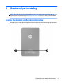
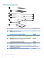
HP Pro Tablet 408 G1
Maintenance and Service Guide
IMPORTANT! This document is intended for
HP authorized service providers only.
© Copyright 2015 Hewlett-Packard
Development Company, L.P.
Bluetooth is a trademark owned by its
proprietor and used by Hewlett-Packard
Company under license. Intel is a U.S.
registered trademark of Intel Corporation.
Microsoft, Windows is a U.S. registered
trademark of Microsoft Corporation. SD Logo is
a trademark of its proprietor.
The information contained herein is subject to
change without notice. The only warranties for
HP products and services are set forth in
the express warranty statements
accompanying such products and services.
Nothing herein should be construed as
constituting an additional warranty. HP shall
not be liable for technical or editorial errors or
omissions contained herein.
First Edition: January 2015
Document Part Number: 798824-001
Product notice
This guide describes features that are common
to most models. Some features may not be
available on your tablet.
Software terms
By installing, copying, downloading, or
otherwise using any software product
preinstalled on this tablet, you agree to be
bound by the terms of the HP End User License
Agreement (EULA). If you do not accept these
license terms, your sole remedy is to return the
entire unused product (hardware and
software) within 14 days for a refund subject
to the refund policy of your place of purchase.
For any further information or to request a full
refund of the tablet, please contact your local
point of sale (the seller).
Safety warning notice
WARNING! To reduce the possibility of heat-related injuries or of overheating the device, do not place
the device directly on your lap or obstruct the device air vents. Use the device only on a hard, flat surface. Do
not allow another hard surface, such as an adjoining optional printer, or a soft surface, such as pillows or
rugs or clothing, to block airflow. Also, do not allow the AC adapter to contact the skin or a soft surface, such
as pillows or rugs or clothing, during operation. The device and the AC adapter comply with the useraccessible surface temperature limits defined by the International Standard for Safety of Information
Technology Equipment (IEC 60950).
iii
iv
Safety warning notice
Table of contents
1 Product description ....................................................................................................................................... 1
2 External component identification ................................................................................................................. 3
3 Illustrated parts catalog ................................................................................................................................ 5
Locating the product number and serial number ................................................................................................. 5
Tablet major components ..................................................................................................................................... 6
Miscellaneous parts ............................................................................................................................................... 7
4 Removal and replacement preliminary requirements ....................................................................................... 9
Tools required ........................................................................................................................................................ 9
Service considerations ........................................................................................................................................... 9
Plastic parts ......................................................................................................................................... 9
Cables and connectors ........................................................................................................................ 9
Grounding guidelines ........................................................................................................................................... 10
Electrostatic discharge damage ....................................................................................................... 10
Packaging and transporting guidelines ......................................................................... 11
Workstation guidelines ................................................................................ 11
5 Removal and replacement procedures ........................................................................................................... 13
Tablet component replacement procedures ...................................................................................................... 13
Unlocking the device and disabling Always On Remote Management ............................................................... 13
Back cover ............................................................................................................................................................ 14
Middle frame and battery .................................................................................................................................... 15
WWAN antenna .................................................................................................................................................... 17
Rear-facing webcam ............................................................................................................................................ 19
System board ....................................................................................................................................................... 20
GPS antenna ........................................................................................................................................................ 23
Transfer board ..................................................................................................................................................... 24
Display panel cable .............................................................................................................................................. 26
Front-facing webcam .......................................................................................................................................... 27
WLAN antenna ..................................................................................................................................................... 28
Speakers .............................................................................................................................................................. 29
v
6 Using HP PC Hardware Diagnostics (UEFI) ...................................................................................................... 31
Downloading HP PC Hardware Diagnostics (UEFI) to a USB device .................................................................... 31
7 Specifications ............................................................................................................................................. 32
8 Backup and recovery .................................................................................................................................... 33
Backing up your information ............................................................................................................................... 33
Performing a system recovery ............................................................................................................................ 33
Changing the boot device order ........................................................................................................ 34
Using Windows Refresh or Windows Reset ...................................................................................... 34
9 Power cord set requirements ........................................................................................................................ 35
Requirements for all countries ........................................................................................................................... 35
Requirements for specific countries and regions ............................................................................................... 35
10 Statement of Volatility .............................................................................................................................. 37
Non-volatile memory usage ................................................................................................................................ 38
Questions and answers ....................................................................................................................................... 40
Using HP Sure Start (select models only) ........................................................................................................... 41
11 Recycling .................................................................................................................................................. 42
Index ............................................................................................................................................................. 43
vi
1
Product description
Category
Description
Product Name
HP Pro Tablet 408 G1
Processor
Intel® Atom Z3736F 1.33-quad core processor soldered-on-circuit (SoC)
Panel
8.0-in, (1280×800), high-definition (HD), 10-point capacitive TouchScreen display assembly
Graphics
Internal graphics: Integrated Intel universal memory architecture (UMA) graphics
Memory
On-board; non-accessible
2-GB DDR3L (4-Gbit, 256-MB × 16, Qty=4)
Mass storage
Supports 32- or 64-GB eMMC
Audio and video
Stereo speakers (2, 0.7-W)
Single digital microphone
2.0-MP, fixed-focus front-facing webcam with activity light
8.0-MP, auto-focus rear-racing webcam with flash
Sensor
Accelerometer
Ambient Light Sensor
eCompass
GPS/AGPS/Glonass
Gyroscope
Hall sensor
SAR sensor
Network
GSM/GPRS/EDGE: Band 2/3/5/8
WCDMA: Band 1/2/4/5/8
Wireless networking
Wireless local area network (WLAN): 802.11a/b/g/n (2.4-GHz, 5.0-GHz) dual band 2×2
Bluetooth: 4.0 LE
SIM card
Micro Subscriber Identity Module (SIM) connector
Support for HP Mobile Connect
External expansion
Micro Secure Digital (SD), expandable up to 128-GB
Ports
●
Type B micro USB 2.0 port with host mode
●
3.5-mm audio jack (4-pole stereo), support for both CTIA and OMTP
●
Micro HDMI
Power requirements
Supports a 4800-mAh, Li-Ion battery (non-removable), USB charging
Supports a 10-W (5.3-V / 2-A) AC adapter with duck head adapter and localized cable
plug support
Operating system
Windows 8.1 with Bing and Office 365 Personal for Small Tablets AFO Multilingual 32-bit
1
Category
Description
Operating system (continued)
Windows 8.1 with Bing for Small Tablets Multilingual 32-bit
Windows 8.1 with Bing for Small Tablets Chinese 32-bit
Windows 8.1 Small Screen Touch 32-bit with Office, Home, and Student CPPP
Windows 8.1 Professional 32-bit
Windows 8.1 Professional 32-bit for Small Tablets
2
Security
Firmware trusted platform module (TPM)
Serviceability
End user replaceable part: AC adapter and USB cable
Chapter 1 Product description
2
External component identification
3
4
Item
Component
Item
Component
(1)
Micro HDMI jack
(8)
Front-facing webcam flash
(2)
Microphone
(9)
Rear-facing webcam
(3)
Micro USB 2.0 port
(10)
WWAN antenna (2)
(4)
Audio-out (headphone)/Audio-in
(microphone) jack
(11)
Volume up button
(5)
Power button
(12)
Volume down button
(6)
WLAN antenna (2)
(13)
Windows button
(7)
Front-facing webcam
(14)
Speakers (2)
Chapter 2 External component identification
3
Illustrated parts catalog
NOTE: HP continually improves and changes product parts. For complete and current information on
supported parts for your computer, go to http://partsurfer.hp.com, select your country or region, and then
follow the on-screen instructions.
Locating the product number and serial number
The tablet product number (1) and serial number (2) are located on the tablet bottom edge. This information
may be needed when travelling internationally or when contacting support.
Locating the product number and serial number
5
Tablet major components
6
Item
Component
Spare part number
(1)
Back cover
805078-001
(2)
Middle frame (includes 4800-mAh, LI battery)
For use only on tablet models equipped with 3G capability
805088-001
For use only on tablet models not equipped with 3G capability
805089-001
(3)
2.0-MP, fixed-focus, front-facing webcam (includes cable and double-sided adhesive)
805086-001
(4)
Display panel cable
805081-001
(5)
WLAN antenna (2, includes antenna cables, transceivers, and double-sided adhesive)
805077-001
(6)
Transfer board (includes cable and double-sided adhesive)
For use only on tablet models equipped with 3G capability
805082-001
For use only on tablet models not equipped with 3G capability
805083-001
(7)
WWAN antenna (2, includes antenna cables, transceivers, and double-sided adhesive)
805076-001
(8)
8.0-MP, auto-focus, rear-facing webcam (includes cable and double-sided adhesive)
805087-001
(9)
GPS antenna: included in the WWAN antenna spare part kit, spare part number 805076-001 (includes antenna cables,
transceivers, and double-sided adhesive)
(10)
Speakers (includes left and right speakers, cable, and double-sided adhesive)
(11)
System board equipped with an Intel Atom Z3736F 1.33-GHz quad core processor (SoC), a graphics subsystem with UMA
memory, and 2.0-GB of system memory
Chapter 3 Illustrated parts catalog
805084-001
Item
(12)
Component
Spare part number
Equipped with 64-GB of eMMC system storage, T-Mobile WWAN capability, and the Windows
8 Professional operating system
808084-601
Equipped with 64-GB of eMMC system storage, T-Mobile WWAN capability, and the Windows
8 Standard operating system
808084-501
Equipped with 64-GB of eMMC system storage, WWAN capability, and the Windows 8
Professional operating system
806368-601
Equipped with 64-GB of eMMC system storage, WWAN capability, and the Windows 8
Standard operating system
806368-501
Equipped with 64-GB of eMMC system storage and the Windows 8 Professional
operating system
805091-601
Equipped with 64-GB of eMMC system storage and the Windows 8 Standard
operating system
805091-601
Equipped with 32-GB of eMMC system storage and the Windows 8 Professional
operating system
805090-601
Equipped with 32-GB of eMMC system storage and the Windows 8 Standard
operating system
805090-601
Display panel assembly, 8.0-in, (1280×800), HD, 10-point capacitive TouchScreen, 16:10
aspect ratio (includes bezel and TouchScreen cable)
805079-001
Miscellaneous parts
Component
Spare part number
10-W (5.3-V / 2-A) AC adapter (includes duck head adapter and USB extension cable)
For use in Australia
806371-002
For use in Brazil
806371-012
For use in Europe
806371-009
For use in India
806371-005
For use in North America
806371-008
For use in the People's Republic of China
806371-006
For use in South Korea
806371-014
For use in the United Kingdom
806371-003
HP Pro Tablet 408 G1 equipped with 8.0-in, (1280×800), HD, 10-point capacitive TouchScreen display assembly, an Intel Atom Z3736F
1.33-GHz quad core processor (SoC), a graphics subsystem with UMA memory, 2.0-GB of system memory, 64-GB of eMMC
system storage, and WWAN capability
For use in Asia Pacific countries and regions
809160-371
For use in Australia
809165-011
For use in Japan
809168-291
For use in the People's Republic of China
809161-AA1
Miscellaneous parts
7
Component
Spare part number
HP Pro Tablet 408 G1 equipped with 8.0-in, (1280×800), HD, 10-point capacitive TouchScreen display assembly, an Intel Atom Z3736F
1.33-GHz quad core processor (SoC), a graphics subsystem with UMA memory, 2.0-GB of system memory, and 64-GB of eMMC
system storage
For use in Asia Pacific countries and regions
809162-371
For use in Australia
809164-011
For use in Japan
809167-291
For use in the People's Republic of China
809163-AA1
For use in the United States
810346-001 and
810350-001
HP Pro Tablet 408 G1 equipped with 8.0-in, (1280×800), HD, 10-point capacitive TouchScreen display assembly, an Intel Atom Z3736F
1.33-GHz quad core processor (SoC), a graphics subsystem with UMA memory, 2.0-GB of system memory, and 32-GB of eMMC
system storage
8
For use in Asia Pacific countries and regions
809158-371
For use in Japan
809166-291
For use in the People's Republic of China
809159-AA1
For use in the United States
810348-001
Plastics Kit (includes gasket, insulator, and tape)
805085-001
Screw Kit
805084-001
Chapter 3 Illustrated parts catalog
4
Removal and replacement preliminary
requirements
Tools required
You will need the following tools to complete the removal and replacement procedures:
●
Magnetic screw driver
●
Phillips P0 screw driver
●
Plastic case utility tool
Service considerations
The following sections include some of the considerations that you must keep in mind during disassembly
and assembly procedures.
NOTE: As you remove each subassembly from the tablet, place the subassembly (and all accompanying
screws) away from the work area to prevent damage.
Plastic parts
CAUTION: Using excessive force during disassembly and reassembly can damage plastic parts. Use care
when handling the plastic parts. Apply pressure only at the points designated in the
maintenance instructions.
Cables and connectors
CAUTION: When servicing the tablet, be sure that cables are placed in their proper locations during the
reassembly process. Improper cable placement can damage the tablet.
Cables must be handled with extreme care to avoid damage. Apply only the tension required to unseat or
seat the cables during removal and insertion. Handle cables by the connector whenever possible. In all cases,
avoid bending, twisting, or tearing cables. Be sure that cables are routed in such a way that they cannot be
caught or snagged by parts being removed or replaced. Handle flex cables with extreme care; these cables
tear easily.
Tools required
9
Grounding guidelines
Electrostatic discharge damage
Electronic components are sensitive to electrostatic discharge (ESD). Circuitry design and structure
determine the degree of sensitivity. Networks built into many integrated circuits provide some protection,
but in many cases, ESD contains enough power to alter device parameters or melt silicon junctions.
A discharge of static electricity from a finger or other conductor can destroy static-sensitive devices or
microcircuitry. Even if the spark is neither felt nor heard, damage may have occurred.
An electronic device exposed to ESD may not be affected at all and can work perfectly throughout a
normal cycle. Or the device may function normally for a while, then degrade in the internal layers, reducing
its life expectancy.
CAUTION: To prevent damage to the tablet when you are removing or installing internal components,
observe these precautions:
Keep components in their electrostatic-safe containers until you are ready to install them.
Before touching an electronic component, discharge static electricity by using the guidelines described in
this section.
Avoid touching pins, leads, and circuitry. Handle electronic components as little as possible.
If you remove a component, place it in an electrostatic-safe container.
The following table shows how humidity affects the electrostatic voltage levels generated by
different activities.
CAUTION:
A product can be degraded by as little as 700 V.
Typical electrostatic voltage levels
Relative humidity
Event
10
10%
40%
55%
Walking across carpet
35,000 V
15,000 V
7,500 V
Walking across vinyl floor
12,000 V
5,000 V
3,000 V
Motions of bench worker
6,000 V
800 V
400 V
Removing DIPS from plastic tube
2,000 V
700 V
400 V
Removing DIPS from vinyl tray
11,500 V
4,000 V
2,000 V
Removing DIPS from Styrofoam
14,500 V
5,000 V
3,500 V
Removing bubble pack from PCB
26,500 V
20,000 V
7,000 V
Packing PCBs in foam-lined box
21,000 V
11,000 V
5,000 V
Chapter 4 Removal and replacement preliminary requirements
Packaging and transporting guidelines
Follow these grounding guidelines when packaging and transporting equipment:
●
To avoid hand contact, transport products in static-safe tubes, bags, or boxes.
●
Protect ESD-sensitive parts and assemblies with conductive or approved containers or packaging.
●
Keep ESD-sensitive parts in their containers until the parts arrive at static-free workstations.
●
Place items on a grounded surface before removing items from their containers.
●
Always be properly grounded when touching a component or assembly.
●
Store reusable ESD-sensitive parts from assemblies in protective packaging or nonconductive foam.
●
Use transporters and conveyors made of antistatic belts and roller bushings. Be sure that mechanized
equipment used for moving materials is wired to ground and that proper materials are selected to avoid
static charging. When grounding is not possible, use an ionizer to dissipate electric charges.
Workstation guidelines
Follow these grounding workstation guidelines:
●
Cover the workstation with approved static-shielding material.
●
Use a wrist strap connected to a properly grounded work surface and use properly grounded tools
and equipment.
●
Use conductive field service tools, such as cutters, screw drivers, and vacuums.
●
When fixtures must directly contact dissipative surfaces, use fixtures made only of staticsafe materials.
●
Keep the work area free of nonconductive materials, such as ordinary plastic assembly aids
and Styrofoam.
●
Handle ESD-sensitive components, parts, and assemblies by the case or PCM laminate. Handle these
items only at static-free workstations.
●
Avoid contact with pins, leads, or circuitry.
●
Turn off power and input signals before inserting or removing connectors or test equipment.
Grounding guidelines
11
Equipment guidelines
Grounding equipment must include either a wrist strap or a foot strap at a grounded workstation.
●
When seated, wear a wrist strap connected to a grounded system. Wrist straps are flexible straps with a
minimum of one megohm ±10% resistance in the ground cords. To provide proper ground, wear a strap
snugly against the skin at all times. On grounded mats with banana-plug connectors, use alligator clips
to connect a wrist strap.
●
When standing, use foot straps and a grounded floor mat. Foot straps (heel, toe, or boot straps) can be
used at standing workstations and are compatible with most types of shoes or boots. On conductive
floors or dissipative floor mats, use foot straps on both feet with a minimum of one megohm resistance
between the operator and ground. To be effective, the conductive must be worn in contact with
the skin.
The following grounding equipment is recommended to prevent electrostatic damage:
●
Antistatic tape
●
Antistatic smocks, aprons, and sleeve protectors
●
Conductive bins and other assembly or soldering aids
●
Nonconductive foam
●
Conductive tabletop workstations with ground cords of one megohm resistance
●
Static-dissipative tables or floor mats with hard ties to the ground
●
Field service kits
●
Static awareness labels
●
Material-handling packages
●
Nonconductive plastic bags, tubes, or boxes
●
Metal tote boxes
●
Electrostatic voltage levels and protective materials
The following table lists the shielding protection provided by antistatic bags and floor mats.
12
Material
Use
Voltage protection level
Antistatic plastics
Bags
1,500 V
Carbon-loaded plastic
Floor mats
7,500 V
Metallized laminate
Floor mats
5,000 V
Chapter 4 Removal and replacement preliminary requirements
5
Removal and replacement procedures
This chapter provides removal and replacement procedures for authorized service provider only parts.
CAUTION: Tablet components described in this chapter should only be accessed by an authorized service
provider. Accessing these parts can damage the tablet and void the warranty.
NOTE: HP continually improves and changes product parts. For complete and current information on
supported parts for your computer, go to http://partsurfer.hp.com, select your country or region, and then
follow the on-screen instructions.
Tablet component replacement procedures
There are as many as 13 screws that must be removed, replaced, and/or loosened when servicing the tablet.
Make special note of each screw size and location during removal and replacement.
Unlocking the device and disabling Always On
Remote Management
HP Touchpoint Manager (HPTM) is a complete cloud-based solution for managing devices. For select HP
devices with the Windows operating system, the Always On Remote Management (AORM) feature is
automatically activated when HP Touchpoint Manager software is installed.
AORM can perform a secure BIOS level lock and can also securely erase internal drives (except for encrypted
self-encrypting drives). The HP Touchpoint Manager website (http://www.hptouchpointmanager.com)
provides access to the AORM lock feature. The device must be unlocked using an authorized PIN from the
same website before you can access HP Computer Setup and start the Windows operating system.
IMPORTANT: A service agent cannot retrieve the PIN from the HP Touchpoint Manager website. If a locked
device is returned for service, the agent must contact the customer to obtain the PIN to unlock the device. If a
PIN is not available, the entire system board must be replaced.
Before returning the device for service, be sure to unlock the device using the PIN from the HP Touchpoint
Manager website (http://www.hptouchpointmanager.com), and also disable the AORM feature in HP
Computer Setup.
To disable AORM:
1.
Access HP Computer Setup (F10).
a.
Turn on or restart the device, and then press esc while the “Press the ESC key for Startup Menu”
message is displayed at the bottom of the screen.
b.
Press f10 to enter Computer Setup.
NOTE: If the BIOS is protected with an Administrator password, enter the password.
2.
Select Advanced, and then select HP Touchpoint Manager Options.
3.
Clear the Allow Activation check box.
4.
Select Save changes and exit.
Tablet component replacement procedures
13
Back cover
Description
Spare part number
Back cover
805078-001
Display panel assembly, 8.0-in, (1280×800), HD, 10-point capacitive TouchScreen, 16:10 aspect ratio
(includes bezel and TouchScreen cable)
805079-001
Before disassembling the tablet, follow these steps:
1.
Turn off the tablet. If you are unsure whether the tablet is off or in Hibernation, turn the tablet on, and
then shut it down through the operating system.
2.
Disconnect the power from the tablet by unplugging the power cord from the tablet.
3.
Disconnect all external devices from the tablet.
Remove the back cover:
CAUTION: Before turning the display panel assembly upside down, make sure the work surface is clear of
tools, screws, and any other foreign objects. Failure to follow this caution can result in damage to the display
panel assembly.
14
1.
Place the tablet on a flat surface, display panel side down, with the volume control buttons toward you.
2.
Insert a thin, plastic tool (1) between the back cover and the middle frame.
3.
Lift the bottom edge of the back cover (2) until it separates from the middle frame.
4.
Remove the back cover (3).
Chapter 5 Removal and replacement procedures
Reverse this procedure to install the back cover.
Middle frame and battery
NOTE:
The middle frame spare part kit includes the 4800-mAh, LI battery.
Description
Spare part number
For use only on tablet models equipped with 3G capability
805088-001
For use only on tablet models not equipped with 3G capability
805089-001
Before removing the middle frame and battery, follow these steps:
1.
Turn off the tablet. If you are unsure whether the tablet is off or in Hibernation, turn the tablet on, and
then shut it down through the operating system.
2.
Disconnect the power from the tablet by unplugging the power cord from the tablet.
3.
Disconnect all external devices from the tablet.
4.
Remove the back cover (see Back cover on page 14).
WARNING! To reduce potential safety issues, use only the battery provided with the tablet, a replacement
battery provided by HP, or a compatible battery purchased from HP.
CAUTION: Removing a battery that is the sole power source for the tablet can cause loss of information.
To prevent loss of information, save your work or shut down the tablet through Windows before removing
the battery.
Remove the middle frame and battery:
1.
Remove the shield (1) and tape (2) the cover the battery cable.
Middle frame and battery
15
16
2.
Disconnect the battery cable (3) from the system board.
3.
Remove the eight Phillips PM2.4×4.8 screws (1) that secure the middle frame to the tablet.
4.
Lift the bottom edge of the middle frame (2) until the display panel cable zero insertion force (ZIF)
connector is accessible.
5.
Release the ZIF connector (3) to which the display panel cable is attached, and then disconnect the
display panel cable from the display panel assembly.
Chapter 5 Removal and replacement procedures
6.
Remove the middle frame (4) and battery.
Reverse this procedure to install the middle frame and battery.
WWAN antenna
Description
Spare part number
WWAN antenna (includes antenna cables, transceivers, and double-sided adhesive)
805076-001
Before removing the WWAN antenna, follow these steps:
1.
Turn off the tablet. If you are unsure whether the tablet is off or in Hibernation, turn the tablet on, and
then shut it down through the operating system.
2.
Disconnect the power from the tablet by unplugging the power cord from the tablet.
3.
Disconnect all external devices from the tablet.
4.
Remove the back cover (see Back cover on page 14).
5.
Remove the middle frame (see Middle frame and battery on page 15).
Remove the WWAN antenna:
1.
Turn the middle frame upside down with the volume control buttons facing away.
2.
Disconnect the WWAN antenna cables from the WWAN terminals (1) on the system board.
3.
Release the WWAN antenna cables from the retention clips (2) built into the middle frame.
WWAN antenna
17
4.
Detach the WWAN antenna transceivers (3) from the middle frame. (The WWAN antenna transceivers
are attached to the middle frame with double-sided adhesive.)
5.
Remove the WWAN antenna (4).
Reverse this procedure to install the WWAN antenna.
18
Chapter 5 Removal and replacement procedures
Rear-facing webcam
Description
Spare part number
8.0-MP, auto-focus, rear-facing webcam (includes cable and double-sided adhesive)
805087-001
Before removing the rear-facing webcam, follow these steps:
1.
Turn off the tablet. If you are unsure whether the tablet is off or in Hibernation, turn the tablet on, and
then shut it down through the operating system.
2.
Disconnect the power from the tablet by unplugging the power cord from the tablet.
3.
Disconnect all external devices from the tablet.
4.
Remove the back cover (see Back cover on page 14).
5.
Remove the middle frame and battery (see Middle frame and battery on page 15).
Remove the rear-facing webcam:
1.
Turn the middle frame upside down with the volume control buttons facing away.
2.
Release the ZIF connector (1) to which the rear-facing webcam is attached, and then disconnect the
rear-facing webcam cable from the system board.
3.
Detach the rear-facing webcam cable (2) from the system board. (The rear-facing webcam cable is
attached to the system board with double-sided adhesive.)
4.
Remove the rear-facing webcam (3).
Reverse this procedure to install the rear-facing webcam.
Rear-facing webcam
19
System board
Description
Spare part number
System board equipped with an Intel Atom Z3736F 1.33-GHz quad core processor (SoC), a graphics subsystem with UMA memory, and
2.0-GB of system memory
Equipped with 64-GB of eMMC system storage, T-Mobile WWAN capability, and the Windows 8
Professional operating system
808084-601
Equipped with 64-GB of eMMC system storage, T-Mobile WWAN capability, and the Windows 8 Standard
operating system
808084-501
Equipped with 64-GB of eMMC system storage, WWAN capability, and the Windows 8 Professional
operating system
806368-601
Equipped with 64-GB of eMMC system storage, WWAN capability, and the Windows 8 Standard
operating system
806368-501
Equipped with 64-GB of eMMC system storage and the Windows 8 Professional operating system
805091-601
Equipped with 64-GB of eMMC system storage and the Windows 8 Standard operating system
805091-601
Equipped with 32-GB of eMMC system storage and the Windows 8 Professional operating system
805090-601
Equipped with 32-GB of eMMC system storage and the Windows 8 Standard operating system
805090-601
Before removing the system board, follow these steps:
1.
Turn off the tablet. If you are unsure whether the tablet is off or in Hibernation, turn the tablet on, and
then shut it down through the operating system.
2.
Disconnect the power from the tablet by unplugging the power cord from the tablet.
3.
Disconnect all external devices from the tablet.
4.
Remove the back cover (see Back cover on page 14).
5.
Remove the middle frame and battery (see Middle frame and battery on page 15).
6.
Remove the rear-facing webcam (see Rear-facing webcam on page 19).
Remove the system board:
1.
20
Remove the shield (1) that covers the WLAN antenna cable connectors.
Chapter 5 Removal and replacement procedures
2.
Remove the shield (2) that covers the display panel cable connector.
System board
21
3.
Disconnect the following cables from the system board:
(1) WLAN antenna cables from the WLAN antenna terminals on the system board
(2) GPS antenna cable from the GPS antenna terminal on the system board
(3) Front-facing webcam cable from the ZIF connector on the system board
(4) Display panel cable from the ZIF connector on the system board
(5) Transfer board cable from the ZIF connector on the system board
22
4.
Turn the middle frame upside down with the volume control buttons facing away.
5.
Disconnect the WWAN antenna cables from the WWAN terminals (1) on the system board.
6.
Remove the five Phillips PM1.9×2.5 screws (2) that secure the system board to the
display panel assembly.
7.
Detach the WLAN antenna transceivers (3) from the system board. (The WLAN antenna transceivers are
attached to the system board with double-sided adhesive.)
8.
Detach the GPS antenna transceiver (4) from the system board. (The GPS antenna transceiver is
attached to the system board with double-sided adhesive.)
Chapter 5 Removal and replacement procedures
9.
Remove the system board (5).
Reverse this procedure to install the system board.
GPS antenna
Description
Spare part number
GPS antenna: included in the WWAN antenna spare part kit, spare part number 805076-001(includes
antenna cables, transceivers, and double-sided adhesive)
TBD-001
Before removing the GPS antenna, follow these steps:
1.
Turn off the tablet. If you are unsure whether the tablet is off or in Hibernation, turn the tablet on, and
then shut it down through the operating system.
2.
Disconnect the power from the tablet by unplugging the power cord from the tablet.
3.
Disconnect all external devices from the tablet.
4.
Remove the back cover (see Back cover on page 14), and then remove the following components:
a.
Middle frame and battery (see Middle frame and battery on page 15)
b.
Rear-facing webcam (see Rear-facing webcam on page 19)
c.
System board (see System board on page 20)
Remove the GPS antenna:
1.
Remove the tape (1) that secures the GPS cable to the middle frame.
GPS antenna
23
2.
Detach the GPS antenna transceiver (2) from the middle frame. (The GPS antenna transceiver is
attached to the middle frame with double-sided adhesive.)
3.
Remove the GPS antenna.
Reverse this procedure to install the GPS antenna.
Transfer board
NOTE: The transfer board spare part kit includes the transfer board cable.
Description
Spare part number
For use only on tablet models equipped with 3G capability
805082-001
For use only on tablet models not equipped with 3G capability
805083-001
Before removing the transfer board, follow these steps:
24
1.
Turn off the tablet. If you are unsure whether the tablet is off or in Hibernation, turn the tablet on, and
then shut it down through the operating system.
2.
Disconnect the power from the tablet by unplugging the power cord from the tablet.
3.
Disconnect all external devices from the tablet.
4.
Remove the back cover (see Back cover on page 14), and then remove the following components:
Chapter 5 Removal and replacement procedures
a.
Middle frame and battery (see Middle frame and battery on page 15)
b.
Rear-facing webcam (see Rear-facing webcam on page 19)
c.
System board (see System board on page 20)
Remove the transfer board:
1.
Disconnect the speaker cable (1) from the transfer board.
2.
Detach the transfer board cable (2) from the middle frame. (The transfer board cable is attached to the
middle frame with double-sided adhesive.)
3.
Detach the transfer board (3) from the middle frame. (The transfer board is attached to the middle
frame with double-sided adhesive.)
4.
Remove the transfer board.
Reverse this procedure to install the transfer board.
Transfer board
25
Display panel cable
Description
Spare part number
Display panel cable
805081-001
Before removing the display panel cable, follow these steps:
1.
Turn off the tablet. If you are unsure whether the tablet is off or in Hibernation, turn the tablet on, and
then shut it down through the operating system.
2.
Disconnect the power from the tablet by unplugging the power cord from the tablet.
3.
Disconnect all external devices from the tablet.
4.
Remove the back cover (see Back cover on page 14), and then remove the following components:
a.
Middle frame and battery (see Middle frame and battery on page 15)
b.
Rear-facing webcam (see Rear-facing webcam on page 19)
c.
System board (see System board on page 20)
Remove the display panel cable:
1.
Detach the display panel cable (1) from the middle frame. (The display panel cable is attached to the
middle frame with double-sided adhesive at two locations.)
2.
Remove the display panel cable (2).
Reverse this procedure to install the display panel cable.
26
Chapter 5 Removal and replacement procedures
Front-facing webcam
Description
Spare part number
2.0-MP, fixed-focus, front-facing webcam (includes cable and double-sided adhesive)
805086-001
Before removing the front-facing webcam, follow these steps:
1.
Turn off the tablet. If you are unsure whether the tablet is off or in Hibernation, turn the tablet on, and
then shut it down through the operating system.
2.
Disconnect the power from the tablet by unplugging the power cord from the tablet.
3.
Disconnect all external devices from the tablet.
4.
Remove the back cover (see Back cover on page 14), and then remove the following components:
a.
Middle frame and battery (see Middle frame and battery on page 15)
b.
Rear-facing webcam (see Rear-facing webcam on page 19)
c.
System board (see System board on page 20)
Remove the front-facing webcam:
1.
Detach the front-facing webcam from the middle frame. (The front-facing webcam is attached to the
middle frame with double-sided adhesive.)
2.
Remove the front-facing webcam.
Reverse this procedure to install the display panel cable.
Front-facing webcam
27
WLAN antenna
Description
Spare part number
WLAN antenna (includes antenna cables, transceivers, and double-sided adhesive)
805077-001
Before removing the WLAN antenna, follow these steps:
1.
Turn off the tablet. If you are unsure whether the tablet is off or in Hibernation, turn the tablet on, and
then shut it down through the operating system.
2.
Disconnect the power from the tablet by unplugging the power cord from the tablet.
3.
Disconnect all external devices from the tablet.
4.
Remove the back cover (see Back cover on page 14), and then remove the following components:
a.
Middle frame and battery (see Middle frame and battery on page 15)
b.
Rear-facing webcam (see Rear-facing webcam on page 19)
c.
System board (see System board on page 20)
Remove the WLAN antenna:
28
1.
Remove the tape (1) that secures the WLAN antenna cable to the middle frame.
2.
Detach the WLAN antenna transceivers (2) from the middle frame. (The WLAN antenna transceivers are
attached to the middle frame with double-sided adhesive.)
3.
Remove the WLAN antenna.
Chapter 5 Removal and replacement procedures
Reverse this procedure to install the WLAN antenna.
Speakers
Description
Spare part number
Speakers (include left and right speakers and cables)
805084-001
Before removing the speakers, follow these steps:
1.
Turn off the tablet. If you are unsure whether the tablet is off or in Hibernation, turn the tablet on, and
then shut it down through the operating system.
2.
Disconnect the power from the tablet by unplugging the power cord from the tablet.
3.
Disconnect all external devices from the tablet.
4.
Remove the back cover (see Back cover on page 14), and then remove the following components:
a.
Middle frame and battery (see Middle frame and battery on page 15)
b.
Rear-facing webcam (see Rear-facing webcam on page 19)
c.
System board (see System board on page 20)
Remove the speakers:
1.
Release the retainers (1) that secure the speakers to the middle frame.
2.
Disconnect the speaker cable (2) from the transfer board.
Speakers
29
3.
Detach the speakers (3) from the middle frame. (The speakers are attached to the middle frame with
double-sided adhesive.)
4.
Remove the speakers.
Reverse this procedure to install the speakers.
30
Chapter 5 Removal and replacement procedures
6
Using HP PC Hardware Diagnostics (UEFI)
HP PC Hardware Diagnostics is a Unified Extensible Firmware Interface (UEFI) that allows you to run
diagnostic tests to determine whether the tablet hardware is functioning properly. The tool runs outside the
operating system so that it can isolate hardware failures from issues that are caused by the
operating system or other software components.
To start HP PC Hardware Diagnostics (UEFI):
1.
Turn off the tablet.
2.
Press and hold the Power and Volume down buttons at the same time until the tablet turns on and
“Esc…pause at startup” is displayed at the bottom of the screen.
The Startup menu is displayed.
3.
Select System Diagnostics.
4.
When the diagnostic tool opens, select the type of diagnostic test you want to run, and then follow the
on-screen instructions.
NOTE:
If you need to stop a diagnostic test, press either the volume up key or the volume down key.
Downloading HP PC Hardware Diagnostics (UEFI) to a USB device
NOTE:
Instructions for downloading HP PC Hardware Diagnostics (UEFI) are provided in English only.
There are two options to download HP PC Hardware Diagnostics to a USB device:
Option 1: HP PC Diagnostics home page— Provides access to the latest UEFI version
1.
Go to http://hp.com/go/techcenter/pcdiags.
2.
Tap the UEFI Download link, and then select Run.
Option 2: Support and Drivers pages—Provide downloads for a specific product for earlier and later
versions
1.
Go to http://www.hp.com.
2.
Tap Support, located at the top of the page, and then tap Download Drivers.
3.
In the text box, enter the product name, and then tap Go.
– or –
Tap Find Now to let HP automatically detect your product.
4.
In the Diagnostic section, tap HP UEFI Support Environment.
– or –
Tap Download, and then select Run.
Downloading HP PC Hardware Diagnostics (UEFI) to a USB device
31
7
Specifications
Metric
U.S.
Width
14.0 cm
5.5 in
Depth
21.5 cm
8.5 in
Height
0.9 cm
0.4 in
Weight (lowest weight configuration)
374 g
0.83 lb
Dimensions (portrait orientation)
NOTE: The tablet operates on DC power, which can be supplied by an AC or a DC power source. The AC power source must be rated at
100–240 V, 50/60 Hz.
NOTE: The tablet can operate on DC power using an industry-standard micro-B USB cable. The HP adapter included with the tablet is
recommended for charging the tablet.
Temperature
Operating
5°C to 35°C
41°F to 95°F
Nonoperating
‑20°C to 60°C
‑4°F to 140°F
Relative humidity (non-condensing)
Operating
10% to 90%
Nonoperating
5% to 95%
Maximum altitude (unpressurized)
Operating
‑15 m to 3,048 m
‑50 ft to 10,000 ft
Nonoperating
‑15 m to 12,192 m
‑50 ft to 40,000 ft
NOTE: Applicable product safety standards specify thermal limits for plastic surfaces. The device operates well within this range of
temperatures.
32
Chapter 7 Specifications
8
Backup and recovery
To protect information, use Windows backup and restore utilities to back up individual files and folders, back
up the entire hard drive, or create system restore points. In case of system failure, use the backup files to
restore the contents of the tablet.
1.
2.
Tap
, and then tap the search box.
In the search box, type restore, and then select from the list of displayed options.
NOTE: For detailed instructions on various backup and restore options, perform a search for these topics in
Windows Help and Support.
In case of system instability, HP recommends that you print the recovery procedures and save them for later
use.
NOTE: Windows includes the User Account Control feature to improve the security of your tablet. You may
be prompted for your permission or password for tasks such as installing software, running utilities, or
changing Windows settings. For more information, see Windows Help and Support.
Backing up your information
Recovery after a system failure is as good as your most recent backup. You should create system repair
media and your initial backup immediately after initial system setup. As you add new software and data files,
you should continue to back up your system on a regular basis to maintain a reasonably current backup.
For more information on the Windows backup features, see Windows Help and Support.
Performing a system recovery
In case of system failure or instability, the tablet provides the following tools to recover your files:
●
Windows recovery tools: You can use Windows Backup and Restore to recover information you have
previously backed up. You can also use Windows Automatic Repair to fix problems that might prevent
Windows from starting correctly.
NOTE:
If you are unable to boot (start up) your tablet, contact support.
Backing up your information
33
Changing the boot device order
To change the boot order so that you can boot from an external device:
NOTE: An external flash drive is required to perform this procedure.
1.
If possible, back up all personal files.
2.
Shut down the tablet.
3.
Connect the external flash drive.
4.
Turn off the tablet.
5.
Press and hold the Power and Volume down buttons at the same time until the tablet turns on and
“Esc…pause at startup” is displayed at the bottom of the screen.
The Startup menu is displayed.
6.
Tap F9 Boot Options.
7.
Select the external flash drive as the boot device.
8.
Restart the tablet.
Using Windows Refresh or Windows Reset
When your tablet is not working properly and you need to regain system stability, the Windows Refresh
option allows you to start fresh and keep what is important to you.
The Windows Reset option allows you to perform detailed reformatting of your tablet, or remove personal
information before you give away or recycle your tablet. For more information on these features, see
Windows Help and Support.
34
Chapter 8 Backup and recovery
9
Power cord set requirements
The wide-range input feature of the tablet permits it to operate from any line voltage from 100 to 120 volts
AC, or from 220 to 240 volts AC.
The 3-conductor power cord set included with the tablet meets the requirements for use in the country or
region where the equipment is purchased.
Power cord sets for use in other countries and regions must meet the requirements of the country or region
where the tablet is used.
Requirements for all countries
The following requirements are applicable to all countries and regions:
●
The length of the power cord set must be at least 1.0 m (3.3 ft) and no more than 2.0 m (6.5 ft).
●
All power cord sets must be approved by an acceptable accredited agency responsible for evaluation in
the country or region where the power cord set will be used.
●
The power cord sets must have a minimum current capacity of 10 amps and a nominal voltage rating of
125 or 250 V AC, as required by the power system of each country or region.
●
The appliance coupler must meet the mechanical configuration of an EN 60 320/IEC 320 Standard Sheet
C13 connector for mating with the appliance inlet on the back of the tablet.
Requirements for specific countries and regions
Country/region
Accredited agency
Applicable note number
Australia
EANSW
1
Austria
OVE
1
Belgium
CEBC
1
Canada
CSA
2
Denmark
DEMKO
1
Finland
FIMKO
1
France
UTE
1
Germany
VDE
1
Italy
IMQ
1
Japan
METI
3
The Netherlands
KEMA
1
Norway
NEMKO
1
The People's Republic of China
COC
5
South Korea
EK
4
Requirements for all countries
35
36
Country/region
Accredited agency
Applicable note number
Sweden
CEMKO
1
Switzerland
SEV
1
Taiwan
BSMI
4
The United Kingdom
BSI
1
The United States
UL
2
1.
The flexible cord must be Type HO5VV-F, 3-conductor, 1.0-mm² conductor size. Power cord set fittings (appliance coupler and
wall plug) must bear the certification mark of the agency responsible for evaluation in the country or region where it will be
used.
2.
The flexible cord must be Type SPT-3 or equivalent, No. 18 AWG, 3-conductor. The wall plug must be a two-pole grounding type
with a NEMA 5-15P (15 A, 125 V) or NEMA 6-15P (15 A, 250 V) configuration.
3.
The appliance coupler, flexible cord, and wall plug must bear a “T” mark and registration number in accordance with the
Japanese Dentori Law. The flexible cord must be Type VCT or VCTF, 3-conductor, 1.00-mm² conductor size. The wall plug must
be a two-pole grounding type with a Japanese Industrial Standard C8303 (7 A, 125 V) configuration.
4.
The flexible cord must be Type RVV, 3-conductor, 0.75-mm² conductor size. Power cord set fittings (appliance coupler and wall
plug) must bear the certification mark of the agency responsible for evaluation in the country or region where it will be used.
5.
The flexible cord must be Type VCTF, 3-conductor, 0.75-mm² conductor size. Power cord set fittings (appliance coupler and wall
plug) must bear the certification mark of the agency responsible for evaluation in the country or region where it will be used.
Chapter 9 Power cord set requirements
10 Statement of Volatility
The purpose of this chapter is to provide general information regarding nonvolatile memory in industrystandards based HP Business Notebook PC systems and provide general instructions for restoring
nonvolatile memory that can contain personal data after the system has been powered off and the hard drive
has been removed.
HP Business Notebook PC products that use Intel®-based or AMD®-based system boards contain volatile DDR
memory. The amount of nonvolatile memory present in the system depends upon the system configuration.
Intel-based and AMD-based system boards contain nonvolatile memory subcomponents as originally
shipped from HP assuming that no subsequent modifications have been made to the system and assuming
that no applications, features, or functionality have been added to or installed on the system.
Following system shutdown and removal of all power sources from an HP Business Notebook PC system,
personal data can remain on volatile system memory (DIMMs) for a finite period of time and will also remain
in nonvolatile memory. The steps below will remove personal data from the notebook PC, including
the nonvolatile memory found in Intel-based and AMD-based system boards.
1.
Follow steps (a) through (j) below to restore the nonvolatile memory that can contain personal data.
Restoring or re-programming nonvolatile memory that does not store personal data is neither
necessary nor recommended.
a.
Enter BIOS (F10) Setup by powering on the system and pressing F10 when prompted near
the bottom of the display, or press the ESC key to display the start up menu, then press F10. If
the system has a BIOS administrator password, enter the password at the prompt.
b.
Select Main > Restore Defaults.
c.
Select the Security menu, and then Restore Security Level Defaults.
d.
If an asset or ownership tag is set, select the Security menu and scroll down to the Utilities menu.
Select System IDs, and the select Asset Tracking Number. Press the spacebar once to clear
the tag, then press Enter to return to the prior menu.
e.
If a DriveLock password is set, select the Security menu, scroll down to Hard Drive Tools under
the Utilities menu, select Hard Drive Tools, select DriveLock, then uncheck DriveLock password
on restart.
f.
If an Automatic DriveLock password is set, select the Security menu, scroll down to Hard Drive
Tools under the Utilities menu, select Hard Drive Tools, scroll down to Automatic DriveLock,
then select the desired hard drive and disable protection. At the automatic drive lock warning
screen, select Yes to continue. Repeat this procedure if more than one hard drive has an Automatic
DriveLock password.
g.
Select the Main menu, then Reset BIOS Security to factory default. Click yes at the warning
message.
h.
Select the Main menu, then Save Changes and Exit.
37
2.
i.
Reboot the system. If the system has a Trusted Platform Module (TPM) and/or fingerprint sensor,
one or two prompts will appear. One to clear the TPM and the other to Reset Fingerprint Sensor;
press F1 to accept or F2 to reject.
j.
Remove all power and system batteries for at least 24 hours.
Remove and retain the storage drive or clear the contents of the drive.
Clear the drive contents by using the BIOS Setup Secure Erase command option, or by using a third party
utility designed to erase data from an SSD. To run Secure Erase, follow these steps:
a.
Enter BIOS Setup by powering on the system, and then pressing F10 when prompted near
the bottom of the display.
b.
Select the Security menu and scroll down to the Utilities menu.
c.
Select Hard Drive Tools.
d.
Under Utilities, select Secure Erase, and then select the desired hard drive.
Non-volatile memory usage
Non Volatile
Memory Type
Amount
(Size)
Does this
memory
store
customer
data?
Does this
memory
retain data
when power
is removed?
What is
the purpose of
this memory?
How is data input into this
memory?
How is this memory write
protected?
HP Sure Start
flash (select
models only)
2 MB
No
Yes
Provides
protected
backup of
critical System
BIOS code, EC
firmware, and
critical PC
configuration
data for select
platforms that
support HP Sure
Start.
Data cannot be written to this
device via the host processor.
The content is managed
solely by the HP Sure Start
Embedded Controller.
This memory is protected
by the HP Sure Start
Embedded Controller.
For more
information,
see Using HP
Sure Start
(select models
only)
on page 41.
38
Real Time Clock
(RTC) battery
backed-up CMOS
configuration
memory (CMOS)
256 Bytes
No
Yes
Stores system
date and time
and limited
keyboard
controller data.
Using the F10 Setup utility or
changing the Microsoft
Windows date & time.
This memory is not writeprotected. HP
recommends password
protecting the F10 Setup
utility.
Controller (NIC)
EEPROM
64 Kbytes
(not customer
accessible)
No
Yes
Store NIC
configuration
and NIC
firmware.
Using a utility from the NIC
vendor that can be run from
DOS.
A utility is required to
write data to this memory
and is available from NIC
vendor. Writing data to
this ROM in an
inappropriate manner will
render the NIC nonfunctional.
Chapter 10 Statement of Volatility
Non Volatile
Memory Type
Amount
(Size)
Does this
memory
store
customer
data?
Does this
memory
retain data
when power
is removed?
What is
the purpose of
this memory?
How is data input into this
memory?
How is this memory write
protected?
Keyboard ROM
64 Kbytes
(not customer
accessible)
No
Yes
Stores firmware
code (keyboard,
mouse, &
battery
management).
Programmed at the factory.
Code is updated when
the system BIOS is updated.
A utility is required for
writing data to this
memory and is available
on the HP website. Writing
data to this ROM in an
inappropriate manner can
render the PC nonfunctional.
DIMM Serial
Presence Detect
(SPD)
configuration data
256 Bytes per
memory
module, 128
Bytes
programmabl
e (not
customer
accessible)
No
Yes
Stores memory
module
information.
Programmed by the memory
vendor.
Data cannot be written to
this memory when
the module is installed in
a PC. The specific write
protection method varies
by memory vendor.
System BIOS
4 to 5 MBytes
Yes
Yes
Store system
BIOS code and
PC
configuration
data.
System BIOS code is
programmed at the factory.
Code is updated when
the system BIOS is updated.
Configuration data and
settings are input using
the F10 setup utility or a
custom utility.
A utility is required for
writing data to this
memory and is available
on the HP website. Writing
data to this ROM in an
inappropriate manner can
render the PC nonfunctional.
Intel Management 1.5 or 5MByte
Engine Firmware
(present only in
specific ZBook and
EliteBook models.
For more
information, go to
http://www.hp.com/
support, and
select your
country. Select
Drivers &
Downloads, and
then follow
the on-screen
instructions.)
Yes
Yes
Stores
Management
Engine Code,
Settings,
Provisioning
Data and iAMT
third party data
store.
Management Engine Code is
programmed at the factory.
Code is updated via Intel
secure firmware update
utility. Unique Provisioning
Data can be entered at
the factory or by an
administrator using
the Management Engine
(MEBx) setup utility. The third
party data store contents can
populated by a remote
management console or local
applications registered by an
administrator to have access
to the space.
The Intel chipset is
configured to enforce HW
protection to block all
direct read/write access
to this area. An Intel
utility is required for
updating the firmware.
Only firmware updates
digitally signed by Intel
can be applied using this
utility.
Bluetooth flash
2Mbit
No
Yes
Stores
Bluetooth
configuration
and firmware.
Programmed at the factory.
Tools for writing data to this
memory are not publicly
available but can be obtained
from the silicon vendor.
A utility is required for
writing data to this
memory and is made
available through newer
versions of the driver if
the flash requires an
upgrade.
802.11 WLAN
EEPROM
4kb to 8kb
No
Yes
Stores
configuration
and calibration
data.
Programmed at the factory.
Tools for writing data to this
memory are not made public.
A utility is required for
writing data to this
memory and is typically
not made available to
the public unless a
firmware upgrade is
Non-volatile memory usage
39
Non Volatile
Memory Type
Amount
(Size)
Does this
memory
store
customer
data?
Does this
memory
retain data
when power
is removed?
What is
the purpose of
this memory?
How is data input into this
memory?
How is this memory write
protected?
necessary to address a
unique issue.
Web Camera
64K bit
No
Yes
Store Web Cam
configuration
and firmware.
Using a utility from the device
manufacturer that can be run
from Windows.
A utility is required for
writing data to this
memory and is typically
not made available to
the public unless a
firmware upgrade is
necessary to address a
unique issue.
Fingerprint Reader
512kByte
Flash
Yes
Yes
Stores
fingerprint
templates.
By enrolling in HP
ProtectTools Security
Manager.
Only a digitally signed
application can make
the call to write to
the flash.
Questions and answers
1.
2.
How can the BIOS settings be restored (returned to factory settings)?
a.
Turn on or restart the computer and press F10 when prompted near the bottom of the display.
b.
Select Main, then select Restore defaults.
c.
Follow the on-screen instructions.
d.
Select Main, save changes and exit, then press Enter.
What kind of configuration data is stored on the DIMM Serial Presence Detect (SPD) memory
module? How would this data be written?
The DIMM SPD memory contains information about the memory module such as size, serial number,
data width, speed/timing, voltage and thermal information. This information is written by the module
manufacturer and stored on an EEPROM. This EEPROM cannot be written to when the memory module is
installed in a PC. Third party tools do exist that can write to the EEPROM when the memory module is
not installed in a PC. There are various third party tools available to read SPD memory.
3.
Does the “Firmware Hub for System BIOS” contain the BIOS program? Is this chip writable, and if so
how?
The Firmware Hub does contain the BIOS program and is writable. A utility is required to perform
the write function.
4.
In some PC systems, the Firmware Hub for System BIOS is a flash memory chip so that updates can
be written by the customer. Is this true for these BIOS chips?
Yes, they are flash memory chips.
5.
What is meant by “Restore the nonvolatile memory found in Intel-based system boards”?
This relates to clearing the Real Time Clock (RTC) CMOS memory that contains PC configuration data.
6.
40
Does resetting the CMOS configuration memory return the PC back to factory defaults?
Chapter 10 Statement of Volatility
The process of resetting the CMOS will return certain system settings to factory default but will not
reset many of the system data and configuration defaults to their factory settings. To return these
system data and configuration defaults to factory settings, refer to question and answer 1 and follow
the instructions for returning the BIOS settings to factory defaults.
Using HP Sure Start (select models only)
Select computer models are configured with HP Sure Start, a technology that continuously monitors your
computer's BIOS for attacks or corruption. If the BIOS becomes corrupted or is attacked, HP Sure Start
restores the BIOS to its previously safe state automatically, without user intervention. Those select
computer models ship with HP Sure Start configured and enabled. Most users can use HP Sure Start with
the default configuration.
To access the latest documentation on HP Sure Start, go to http://www.hp.com/support, and select your
country. Select Drivers & Downloads, and then follow the on-screen instructions.
Using HP Sure Start (select models only)
41
11 Recycling
When a non-rechargeable or rechargeable battery has reached the end of its useful life, do not dispose of the
battery in general household waste. Follow the local laws and regulations in your area for battery disposal.
HP encourages customers to recycle used electronic hardware, HP original print cartridges, and rechargeable
batteries. For more information about recycling programs, see the HP Web site at http://www.hp.com/
recycle.
42
Chapter 11 Recycling
Index
A
AC adapter, spare part numbers 7
antenna
location 4
removal 17, 23, 28
spare part numbers 6, 17, 23,
28
audio, product description 1
audio-in jack 4
audio-out jack 4
B
back cover
removal 14
spare part number 6, 14
battery
removal 15
spare part numbers 6, 15
buttons
power 4
volume down 4
volume up 4
Windows 4
C
cables, service considerations 9
connectors, service considerations
9
D
display panel assembly, spare part
number 7, 14
display panel cable
removal 26
spare part number 6, 26
display panel, product description 1
E
electrostatic discharge 10
equipment guidelines 12
external expansion, product
description 1
F
front-facing webcam
location 4
removal 27
spare part number 6, 27
front-facing webcam flash 4
G
GPS antenna
removal 23
spare part number 6, 23
graphics, product description 1
grounding guidelines 10
guidelines
equipment 12
grounding 10
packaging 11
transporting 11
workstation 11
H
HDMI jack 4
headphone jack 4
HP PC Hardware Diagnostics (UEFI)
downloading 31
HP Sure Start 41
J
jacks
audio-in 4
audio-out 4
HDMI 4
headphone 4
microphone 4
M
mass storage device, product
description 1
memory
nonvolatile 37
volatile 37
memory module, product
description 1
microphone
location 4
product description 1
microphone jack 4
middle frame
removal 15
spare part numbers 6, 15
model name 1
N
network, product description 1
nonvolatile memory 37
O
operating system, product
description 1, 2
P
packaging guidelines 11
plastic parts, service
considerations 9
Plastics Kit, spare part number 8
ports
product description 1
USB 4
power button 4
power cord, set requirements 35
power requirements, product
description 1
processor, product description 1
product description
audio 1
display panel 1
external expansion 1
graphics 1
mass storage 1
memory module 1
microphone 1
network 1
operating system 1, 2
ports 1
power requirements 1
processors 1
product name 1
security 2
Index
43
sensor 1
serviceability 2
SIM card 1
video 1
wireless networking
product name 1
V
video, product description
volume down button 4
volume up button 4
1
R
rear-facing webcam
location 4
removal 19
spare part number 6, 19
recovery 34
refresh 34
removing personal data from volatile
system memory 37
S
Screw Kit, spare part number 8
security, product description 2
sensor, product description 1
service considerations
cables 9
connectors 9
plastic parts 9
serviceability, product description 2
SIM card, product description 1
speakers
location 4
removal 29
spare part number 6, 29
system board
removal 20
spare part numbers 6, 20
system memory, removing personal
data from volatile 37
T
tablet
major components 6
spare part numbers 7, 8
specifications 32
tools required 9
transfer board
removal 24
spare part numbers 6, 24
transporting guidelines 11
U
USB port, location
44
Index
4
1
W
webcam
removal 19, 27
spare part numbers 6, 19, 27
Windows button 4
Windows Refresh 34
Windows Reset 34
wireless antenna
location 4
removal 17, 23, 28
spare part numbers 6, 17, 23,
28
wireless networking, product
description 1
WLAN antenna
location 4
removal 28
spare part number 6, 28
workstation guidelines 11
WWAN antenna
location 4
removal 17
spare part number 6, 17