1
PowerFlex® 700S Drives with Phase II Control (3.01)
1
Firmware Release Notes
PowerFlex® 700S Drives with Phase II Control
(3.01)
These release notes correspond to major revision 3, minor revision 1 of
firmware for PowerFlex 700S drives with Phase II control.
Introduction
Determining Firmware
Revision Level
These release notes provide the following information:
For information about:
See page:
Determining Firmware Revision Level
Upgrading from Previous Releases
Known Anomaly
Corrected Anomalies
Enhancements
New and Changed Parameters
Restrictions
1
1
2
2
4
11
17
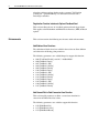
To determine the firmware version for a PowerFlex 700S drive, view
parameters 314 [VPL Firmware Rev] and 315 [VPL Build Number]. The
firmware version is the combination of the data in these parameters.
Example:
Firmware Version 3.01.01
Firmware revision from parameter 314 [VPL Firmware Rev]
Firmware build number from parameter 315 [VPL Build Number]
Upgrading from Previous
Releases
The boot code has been updated after the v2.xx release and the v2.xx release
or later needs the updated boot code (boot v1.06). When the firmware is
upgraded from the version before v2.xx (i.e., v1.12), the following
procedure is required for upgrading the boot code along with the application
code:
If the firmware is upgraded from the version after v2.xx (i.e., v2.03),
upgrading the application only is required:
2
PowerFlex® 700S Drives with Phase II Control (3.01)
Upgrading from version 1.12 (or before 2.xx release)
1. Flash 700S2bt01_06.bin using 1203-SSS Series B and HyperTerminal.
2. Cycle the power (automatically).
3. HIM displays "No System Application..." error message - ignore this
error.
4. Flash 700S2ap02_06.bin using 1203-SSS Series B and HyperTerminal.
5. Cycle the power (automatically).
6. HIM displays as normal.
Known Anomaly
Firmware revision 3.01 contains the following known anomaly:
Motion Time Keeper - No CST Detected
This is an anomaly with RSLogix™ 5000. An RSLogix program can
produce an incorrect value for the coarse multiplier in the Config Data
block. This causes an axis fault due to the controller and drive having
different coarse update periods.
This anomaly has a work around. Change the Coarse Update Rate to
another value and click the Apply button. Then set the Coarse Update Rate
to the value needed and again click the Apply button. Next, down load the
application program.
Corrected Anomalies
Firmware revision 3.01 contains the following corrections for anomalies:
Control Input Loss
This revision corrects an anomaly in the loss of control input when using
Digital Inputs 4, 5 and 6 for Start/Stop and Run with no HIM attached and
no 20-COMM module present in the drive.
Default Bit Set for High Horsepower Input Phase Loss
The High Horsepower Input Phase Loss event, parameter 370, has been
re-configured to now cause a drive fault (default value changed from 1 “Alarm” to 3 - “Flt RampStop”). This change was made to prevent single
phase operation if a phase loss is experienced.
PowerFlex® 700S Drives with Phase II Control (3.01)
3
Drive Reset with Hi-Resolution Feedback Device
This version corrects an anomaly that would reset the drive due to the
selection of port 0 for a feedback device, parameter 146 [FW TaskTime Sel]
set to a value of 2 and parameter 222 [Mtr Fdbk Sel Pri] set to 2
“Sensorless”.
Enhance Field Weakening Control
This revision provides a more efficient method for entry and exit to/from the
field weakening region.
Improve Motor Control Auto-Tune
The following parameters were added/changed to improve the Motor
Control Auto-tuning function.
533 [Flux Gain Adjust] was added to allow the flux level used to enter the
field weakening range to be adjusted.
552 [Slip Preload Val] was added to allow the Slip Gain value to be
pre-loaded if the drive is powered down.
553 [Slip Slew Rate] was added to set the rate at which the Slip Gain
regulator output transitions from the inactive state to the active state.
Increase the Maximum Brake Pulse and Brake Watts
This revision includes an increase in the maximum value of parameters 416
[Brake PulseWatts] and 417 [Brake Watts].
Motor Auto-Tune and Power Mismatch Fault
The Motor Auto Tune function was enhanced to provide better auto-tuning
performance for this revision. Also, the Horse Power fault received due to a
power mismatch between the motor nameplate value and the motor test
result has been removed.
Negative Numbers for Falling Edge Triggers in Trend Function
This revision provides for the selection of negative numbers in the Trend
Trigger Bit, parameter 565, for a falling edge trigger in the Trend function.
Position Enable Now Turns Off with DriveLogix
Revision 3.01 corrects an anomaly where by the position regulator status,
parameter 741 [Position Status], bit 7 [Regulator On] remained active (true)
4
PowerFlex® 700S Drives with Phase II Control (3.01)
when the position regulator absolute mode, parameter 740 [Position
Control], bit 7 [[AbsoluteMode] was turned off when used with a
DriveLogix controller.
Registration Function Interface to Optional Feedback Card
This revision allows the use of a feedback option on board trigger inputs.
This applies to the Heidenhain and Multi-Device Interface (MDI) feedback
options.
Enhancements
This revision contains the following new features and/or enhancements:
Add/Subtract User Functions
The add/subtract blocks have been added in the revision to allow addition
and subtraction of floating point parameters.
The following parameters were added/changed to support this function:
•
•
•
•
•
•
•
•
•
•
•
•
•
1000 [UserFunct Enable], new bit 5 “AddSub Math”
1096 [AddSub 1 Input]
1097 [AddSub 1 Add]
1098 [AddSub 1 Subtrct]
1099 [AddSub 1 Result]
1100 [AddSub 2 Input]
1101 [AddSub 2 Add]
1102 [AddSub 2 Subtrct]
1103 [AddSub 2 Result]
1104 [AddSub 3 Input]
1105 [AddSub 3 Add]
1106 [AddSub 3 Subtrct]
1107 [AddSub 3 Result]
Add Second DInt to Real Conversion User Function
This revision adds parameters to allow a second user function for
conversion of DInt to Real data values.
The following parameters were added to support this function:
• 1150 [DInt2Real2 In]
• 1151 [DInt2Real2 Scale]
• 1152 [DInt2Real2Result]
PowerFlex® 700S Drives with Phase II Control (3.01)
5
Add SynchLink™ Comm format 14: 1A-3D-14B
This revision includes a new communication format for receiving
SynchLink data which will allow the drive to receive position data that can
be used as a position reference.
The following parameter changes were made to support this function:
• 905 [SL Rx CommFormat] and 910 [SL Tx Comm Frmt], option 14 1A, 3D, 14B is new.
Analog Input Loss Detection
This revision adds the ability to determine the drive’s response to an analog
input loss.
The following parameters were added/changed to support this function:
•
•
•
•
1093 [Analog In 1 Loss] is new
1094 [Analog In 2 Loss] is new
1095 [Analog In 3 Loss] is new
322 [Exception Event3] was changed to include bit 29 [AnlgIn1 Loss],
bit 30 [AnlgIn2 Loss] and bit 31 [AnlgIn3 Loss]
The following new faults were added to support this function:
• 94 - Analog In 1 Loss
• 95 - Analog In 2 Loss
• 96 - Analog In 3 Loss
First Differential Speed Feedback Input for Inertia Adaptation
This revision adds the first difference feedback selection input for Inertia
Adaptation.
The following parameter was changed to support this function:
• 132 [Inert Adapt Sel], bit 2 [First Diff]
Flux Current Out of Range Fault Added and Horse Power Fault
Eliminated in Autotune
This revision adds a Flux Current Out of Range fault which replaces the
Horsepower Fault in the Autotune function. Bit 17 of parameter 465 will be
set to indicate that the Flux Current calculation is out of range if the flux
current value is greater than 90% of rated motor current.
The following parameter was changed to support this function:
• 465 [MC Diag Error 3], bit 17 [IFlux Range]
6
PowerFlex® 700S Drives with Phase II Control (3.01)
Heidenhain Encoder Interface (Endat 24 bit Single-Turn)
This version adds support for the Heidenhain Absolute Angle encoders
RCN727 and RCN827. The Heidenhain feedback option must be upgraded
to version 2.01 in order for this feature to work.
The following parameter changes were made to support this function:
• 264 [Heidenhain0 Stat], bit 14 was changed from [Endat BootEr] to
[Bootup Error] and bit 15 [FW VersionErr] is new
• 266 [Heidn Encdr Type]. The default value and maximum value have
been changed.
LED Statuses Display on HIM and in Application Programs
With this revision you can now monitor LED statuses, including the main
controller, SynchLink and DriveLogix5370 from a HIM or an application
program (e.g., DriveExplorer™). This feature is only available with
DriveLogix version 15.03 or later. Refer to HIM LED Status Options Not
Supported on page 18 for more information.
The following new parameter was added to support this function:
• 554 [LED Status]
Motion Planner (Trapezoidal Point-to-Point Position Control)
The Point-to-Point Motion Planner function was added to this revision. This
function allows the drive to execute point-to-point position moves using a
Trapezoidal profile. Adjustments can be made to the acceleration,
deceleration and S-curve times.
The following parameters were added/changed to support this function:
•
•
•
•
•
•
•
•
•
•
•
•
•
•
•
•
•
147 [FW Functions En], bit 19 [MotinPlanner]
149 [FW FunctionsActl], bit 19 [MotinPlanner]
1130 [PPMP Pos Command]
1131 [PPMP Pos Mul]
1132 [PPMP Pos Div]
1133 [PPMP Scaled Cmd]
1134 [PPMP Control]
1135 [PPMP Status]
1136 [PPMP Rev Spd Lim]
1137 [PPMP Fwd Spd Lim]
1138 [PPMP Over Ride]
1139 [PPMP Accel Time]
1140 [PPMP Decel Time]
1141 [PPMP SCurve Time]
1142 [PPMP Spd Output]
1143 [PPMP Pos Output]
1144 [PPMP Pos To Go]
PowerFlex® 700S Drives with Phase II Control (3.01)
7
• 1145 [PPMP TP Select]
• 1146 [PPMP TP DataDInt]
• 1147 [PPMP TP DataReal]
Motor Overload Thermal Retention (NEC Requirement)
This revision adds the ability to retain motor temperature information after
the drive is powered down. This feature is enabled by setting bit 20 “Motor
OL Ret” of parameter 153 [Control Options]. When the drive is powered up,
the stored motor temperature value is used as an initial value for the motor
overload function. If the feature is disabled, the initial value for the motor
temperature is zero (0). The stored motor temperature value can be reset to
zero by toggling bit 20 of parameter 153 from “1” to “0”, and back to “1”.
The following parameters were added/changed to support this function:
• 153 [Control Options], bit 20 [Motor OL Ret]
• 341 [Mtr I2T Count]
On/Off Delay Timers for Digital Outputs
This revision adds On/Off delay timers for use with digital outputs. Each
digital output now has two user-controlled timers associated with it. One
timer (the ON timer) defines the delay time between a FALSE to TRUE
transition (condition appears) on the output condition and the corresponding
change in state of the digital output. The second timer (the OFF timer)
defines the delay time between a TRUE to FALSE transition (condition
disappears) on the output condition and the corresponding change in the
state of the digital output.
The following new parameters were added to support this function:
•
•
•
•
•
•
848 [Dig Out1 On Time]
849 [Dig Out1 OffTime]
853 [Dig Out2 On Time]
854 [Dig Out2 OffTime]
858 [Rly Out3 On Time]
859 [Rly Out3 OffTime]
On-Off Delay Timer User Functions
This revision adds On/Off delay timers for use with user functions. This
feature provides the ability to set delay timers for two channels: two
channels ON, or two channels OFF, or one channel ON and one channel
OFF. The ON timer defines the delay time between a FALSE to TRUE
transition (condition appears) on the output condition and the corresponding
change in state of an input/output. The second timer (the OFF timer) defines
the delay time between a TRUE to FALSE transition (condition disappears)
8
PowerFlex® 700S Drives with Phase II Control (3.01)
on the output condition and the corresponding change in the state of the
digital output.
The following parameters were added/changed to support this function:
•
•
•
•
•
•
•
•
•
•
•
1000 [UserFunct Enable], new bit 6 “Delay Timer”
1108 [DelayTimer1 Data]
1109 [DelayTimer1 Bit]
1110 [DelayTimer1PrSet]
1111 [DelayTimer1Accum]
1112 [DelayTimer1Stats]
1113 [DelayTimer2 Data]
1114 [DelayTimer2 Bit]
1115 [DelayTimer2PrSet]
1116 [DelayTimer2Accum]
1117 [DelayTimer2Stats]
Phase Lock Loop
This revision adds a Phase Lock Loop (PLL), which provides a closed loop
position control system. This loop acts on the difference between a
reference (encoder) input and the feedback from the output of a virtual
encoder. The PLL can maintain a precise phase relationship between input
and output.
Virtual master reference
A virtual master reference is provided when position and velocity
references are electronically generated and sent to all drives to follow. There
is no physical shaft or encoder to generate the reference. Each drive is
electronically position locked to a virtual reference. That reference is
generated by a virtual encoder.
Real master reference
A real master reference is provided when position and velocity references
are generated by an encoder attached to and following a physical shaft. The
encoder’s signals are sent to all drives to follow. The encoder signal must
first be conditioned before it is sent out to the following drives. The real
master encoder is conditioned and re-generated by a PLL.
PowerFlex® 700S Drives with Phase II Control (3.01)
The following parameters were added/changed to support this function:
•
•
•
•
•
•
•
•
•
•
•
•
•
•
•
•
•
•
•
•
•
•
54 [Inertia TrqLpfBW]
147 [FW Functions En], bit 24 [PhaseLockLp]
149 [FW FunctionsActl], bit 24 [PhaseLockLp]
717 [PLL TP Select]
718 [PLL TP DataDInt]
719 [PLL TP DataReal]
720 [PLL Control]
721 [PLL Position Ref]
722 [PLL BandWidth]
723 [PLL Rev Input]
724 [PLL Rev Output]
725 [PLL EPR Input]
726 [PLL EPR Output]
727 [PLL VirtEncdrRPM]
728 [PLL Ext Spd Ref]
729 [PLL Ext SpdScale]
730 [PLL LPFilter BW]
731 [PLL Posit Out]
732 [PLL Posit OutAdv]
733 [PLL FiltPositOut]
734 [PLL Speed Out]
735 [PLL SpeedOut Adv]
Security Aware Function
The Security Aware function has been added in this revision and allows a
secure enabled device (e.g., PLC, etc.) to control a drive. When a drive is
Security Aware enabled, a HIM or other communication device cannot be
used to change parameters. However, the Stop button on a HIM, or other
communication device, can be used to stop the drive.
The following new parameters were added to support this function:
•
•
•
•
669 [Write Mask]
712 [Write Mask Act]
713 [Logic Mask Act]
714 [Port Mask Act]
Skip Rotate Autotune in V/Hz Mode
This revision removes the option of using rotate Autotune for the V/Hz
mode from the Start Up Menu. The Start Up Menu now only allows static
motor tuning tests in V/Hz mode.
9
10
PowerFlex® 700S Drives with Phase II Control (3.01)
Slip Frequency Tuning in Start-Up Menu
This revision adds the Slip Frequency Auto Tune function to the Motor
Tests and the Start Up Menu. This test allows the drive to establish the slip
frequency. This value is displayed in parameter 486 [Rated Slip Freq].
The test requires that the motor be run at near 50% (High Horsepower
frames 9 - 12) and 85% (Low Horsepower frames 1 - 6) speeds. The test
repeats three times.
The following parameters were added/changed to support this function:
•
•
•
•
•
150 [Logic State Mach]
153 [Control Options], bit 29 [Slip Test En]
157 [Logic Ctrl State], bits 22 and 23
165 [Tune Test Status], value 7 “Slip Test”
510 [FVC Mode Config], bit 10 [SlipSlewRtEn] and 11 [SlipPrloadEn]
Speed Limited Adjustable Torque (SLAT) Min/Max Mode Control
This revision adds Speed Limited Adjustable Torque (SLAT) Min/Max
Mode controls to allow for applications that require a robust transition from
a torque mode to a speed mode of operation.
The following parameters were added/changed to support this function:
• 110 [Speed/TorqueMode], new values 7 ”SLAT Minimum” and 8 “SLAT
Maximum”
• 119 [SLAT ErrorSetpnt]
• 120 [SLAT Dwell Time]
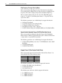
Support Frame 12 (Star-Coupler Parallel Drive)
This revision adds support for the PowerFlex 700S AC Drive Frame 12 at
480v AC/650v DC for the following ratings:
Amps
Cat. Code
HP (kW) - ND
820
920
1030
820
920
1K0
700 (450)
800 (500)
900 (500)
The following parameters were changed to support this function:
• 420 [Pwr Strct Mode], bit 3 [Parallel Drv]
• 322 [Exception Event3]
• 328 {Alarm Status 3]
The following new faults were added to support this function:
• 76 - HiHP HardwareVer
• 77 - HiHP CurrUnblnce
• 78 - HiHP VoltUnblnce
PowerFlex® 700S Drives with Phase II Control (3.01)
New and Changed
Parameters
11
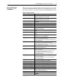
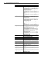
Table A below lists the parameter differences between revision 3.01 and the
revision 2.04 of firmware. Refer to PowerFlex 700S High Performance AC
Drive Phase II Control - User Manual, publication 20D-UM006 for details.
Table A Parameter Changes
Parameter Number [Name]
What Changed
49 [Selected SpdRefA]
This parameter is new and allows viewing of Speed
Reference A, parameter 27, from a HIM
This parameter is new and allows viewing of Speed
Reference B, parameter 28, from a HIM
This parameter is new and supports the new Phase Lock
Loop feature
The maximum value was changed from 600 to 3000
This parameter was changed to non-linkable
The maximum value was changed from 600 to 3000
Options 7 ”SLAT Minimum” and 8 “SLAT Maximum” are new
and support SLAT control
This parameter is new and is used for SLAT Min/Max Mode
Control
This parameter is new and is used for SLAT Min/Max Mode
Control
Bit 2 [First Diff] is new and supports First Differential Speed
Feedback Input for Inertia Adaptation
50 [Selected SpdRefB]
54 [Inertia TrqLpfBW]
81 [Spd Reg P Gain]
84 [SpdReg AntiBckup]
92 [SpdReg P Gain Mx]
110 [Speed/TorqueMode]
119 [SLAT ErrorSetpnt]
120 [SLAT Dwell Time]
132 [Inert Adapt Sel]
147 [FW Functions En]
•
•
149 [FW FunctionsActl]
•
•
Bit 19 [MotinPlanner] is new and is used to enable the
Point-to-Point Motion Planner function
Bit 24 [PhaseLockLp] is new and is used to enable the Phase
Lock Loop feature
Bit 19 [MotinPlanner] is new and is used to display the actual
state of the Point-to-Point Motion Planner function
Bit 24 [PhaseLockLp] is new and is used to display the actual
state of the Phase Lock Loop feature
150 [Logic State Mach]
Option 8 “Slip Test” is new and supports the new Slip
Frequency Auto-tuning feature
153 [Control Options]
•
•
•
157 [Logic Ctrl State]
•
•
165 [Tune Test Status]
222 [Mtr Fdbk Sel Pri]
223 [Mtr Fdbk Sel Alt]
224 [TachSwitch Level]
259 [Stegmann0 Cnfg]
263 [Heidenhain0 Cnfg]
264 [Heidenhain0 Stat]
266 [Heidn Encdr Type]
306 [DC Bus Voltage]
Bit 20 [Motor OL Ret] is new and is used to enable Motor
Over-Load Retention
Bit 21 [Inrt TrqLPEn] is new and is used to enable Inertia
Compensation Torque Output Low Pass Filter
Bit 29 [Slip Test En] is new and is used to enable Slip
Frequency Auto-tuning
Bit 22 [Slip Test En] is new and is used to support Slip
Frequency Auto-tuning
Bit 23 [S Tst FulSpd] is new and is used to support Slip
Frequency Auto-tuning
Option 7 was changed from “Mtr+Sys J” to “Slip Test” and is
used to support Slip Frequency Auto-tuning
This parameter was changed to non-linkable
This parameter was changed to non-linkable
This parameter was changed to non-linkable
This parameter was changed to non-linkable
This parameter was changed to non-linkable
Bit 14 was changed from [Endat BootEr] to [Bootup Error]
and Bit 15 [FW VersionErr] is new
The default value and maximum value have been changed
The maximum value was changed from 1000.0000 to
1170.0000
12
PowerFlex® 700S Drives with Phase II Control (3.01)
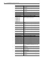
Parameter Number [Name]
What Changed
322 [Exception Event3]
The following bits are new:
•
•
•
•
•
•
325 [Fault Status 3]
The following bits are new:
•
•
•
•
•
•
328 [Alarm Status 3]
•
•
•
•
•
370 [HiHp InPhsLs Cfg]
412 [Power EE TP Sel]
414 [Brake/Bus Cnfg]
416 [Brake PulseWatts]
417 [Brake Watts]
420 [Pwr Strct Mode]
465 [MC Diag Error 3]
466 [MC TP1 Select]
475 [MC FaultTPSelect]
486 [Rated Slip Freq]
490 [StatorInductance]
Bit 11 [HH HW Ver] is used to indicate a High Horsepower
Hardware Version fault
Bit 12 [HH CurUnblnc] is used to indicate a High Horsepower
Output Current Unbalance fault
Bit 13 [HH VltUnblnc] is used to indicate a High Horsepower
Bus Voltage Unbalance fault
Bit 29 [AnlgIn1 Loss] is used to indicate a Analog Input 1 Loss
fault
Bit 30 [AnlgIn2 Loss] is used to indicate a Analog Input 2 Loss
fault
Bit 31 [AnlgIn3 Loss] is used to indicate a Analog Input 3 Loss
fault
The following bits are new:
•
341 [Mtr I2T Count]
Bit 11 [HH HW Ver] is used to indicate a High Horsepower
Hardware Version fault
Bit 12 [HH CurUnblnc] is used to indicate a High Horsepower
Output Current Unbalance fault
Bit 13 [HH VltUnblnc] is used to indicate a High Horsepower
Bus Voltage Unbalance fault
Bit 29 [AnlgIn1 Loss] is used to indicate a Analog Input 1 Loss
fault
Bit 30 [AnlgIn2 Loss] is used to indicate a Analog Input 2 Loss
fault
Bit 31 [AnlgIn3 Loss] is used to indicate a Analog Input 3 Loss
fault
Bit 11 [NonCnfgFault] is used to indicate a non-configurable
High Horsepower Hardware Version fault
Bit 12 [NonCnfgFault] is used to indicate a non-configurable
High Horsepower Output Current Unbalance fault
Bit 13 [NonCnfgFault] is used to indicate a non-configurable
High Horsepower Bus Voltage Unbalance fault
Bit 29 [NonCnfgFault] is used to indicate a non-configurable
Analog Input 1 Loss fault
Bit 30 [NonCnfgFault] is used to indicate a non-configurable
Analog Input 2 Loss fault
Bit 31 [NonCnfgFault] is used to indicate a non-configurable
Analog Input 3 Loss fault
This parameter is new and us used to support the Motor
Overload Thermal Retention feature
The default value was changed from 1 to 3
Options 74 - 92 were changed and options 93 -111 are new
Bits 5 [Fast Braking] and 6 [DC Braking] were added to
support parameters 416 [Brake PulseWatts] and 417 [Brake
Watts]. This parameter was also changed to non-linkable
The maximum value was changed to 100,000,000
The maximum value was changed 500,000
Bit 3 [Parallel Drv] is new and is used to support the start
coupler for frame 12 drives only
The bit enumeration was changed to support Motor Control
diagnostics
New option values were added to support Motor Control
diagnostics
New option values were added to support Motor Control
diagnostics
Changed the attributes to allow changing this parameter
while the drive is running
Changed the default value from 8192 to 4096
PowerFlex® 700S Drives with Phase II Control (3.01)
13
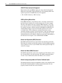
Parameter Number [Name]
What Changed
510 [FVC Mode Config]
Bits 10 [SlipSlewRtEn] and 11 [SlipPrloadEn] were added
and support Slip Frequency tuning
This parameter was changed to non-linkable
This parameter was changed to non-linkable
This parameter was changed to non-linkable
This parameter is new and is used to support Motor Control
This parameter is now linkable
This parameter is now linkable
This parameter is new and is used to support Motor Control
This parameter is new and is used to support Motor Control
This parameter is new and is used to support Motor Control
This parameter is new and is used for the LED Status
Display from HIM and Application Programs feature
This parameter is new and is used to support the Security
Aware feature
This parameter is new and is used to support the Security
Aware feature
This parameter is new and is used to support the Security
Aware feature
This parameter is new and is used to support the Security
Aware feature
This parameter is new and supports the new Phase Lock
Loop feature
This parameter is new and supports the new Phase Lock
Loop feature
This parameter is new and supports the new Phase Lock
Loop feature
This parameter is new and supports the new Phase Lock
Loop feature
This parameter is new and supports the new Phase Lock
Loop feature
This parameter is new and supports the new Phase Lock
Loop feature
This parameter is new and supports the new Phase Lock
Loop feature
This parameter is new and supports the new Phase Lock
Loop feature
This parameter is new and supports the new Phase Lock
Loop feature
This parameter is new and supports the new Phase Lock
Loop feature
This parameter is new and supports the new Phase Lock
Loop feature
This parameter is new and supports the new Phase Lock
Loop feature
This parameter is new and supports the new Phase Lock
Loop feature
This parameter is new and supports the new Phase Lock
Loop feature
This parameter is new and supports the new Phase Lock
Loop feature
This parameter is new and supports the new Phase Lock
Loop feature
511 [FVC2 Mode Config]
512 [PMag Mode Config]
514 [Test Mode Config]
533 [Flux Gain Adjust]
549 [Vuv Fdbk Offset]
550 [Vvw Fdbk Offset]
551 [CurrFdbk AdjTime]
552 [Slip Preload Val]
553 [Slip Slew Rate]
554 [LED Status]
669 [Write Mask]
712 [Write Mask Act]
713 [Logic Mask Act]
714 [Port Mask Act]
717 [PLL TP Select]
718 [PLL TP DataDInt]
719 [PLL TP DataReal]
720 [PLL Control]
721 [PLL Position Ref]
722 [PLL BandWidth]
723 [PLL Rev Input]
724 [PLL Rev Output]
725 [PLL EPR Input]
726 [PLL EPR Output]
727 [PLL VirtEncdrRPM]
728 [PLL Ext Spd Ref]
729 [PLL Ext SpdScale]
730 [PLL LPFilter BW]
731 [PLL Posit Out]
732 [PLL Posit OutAdv]
14
PowerFlex® 700S Drives with Phase II Control (3.01)
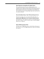
Parameter Number [Name]
What Changed
733 [PLL FiltPositOut]
This parameter is new and supports the new Phase Lock
Loop feature
This parameter is new and supports the new Phase Lock
Loop feature
This parameter is new and supports the new Phase Lock
Loop feature
Added bits 24 - 29 to support the Homing function
Added bits 13 - 15 to support the Homing function
This parameter was changed to non-linkable
This parameter was changed to non-linkable
This parameter was changed to non-linkable
Option 39 “Home Switch” is new and supports the
Point-to-Point Motion Planner function
734 [PLL Speed Out]
735 [PLL SpeedOut Adv]
740 [Position Control]
741 [Position Status]
742 [Position Ref Sel]
777 [PositionFdbk Sel]
796 [Posit Gear Ratio]
825 [Dig In1 Sel]
826 [Dig In2 Sel]
827 [Dig In3 Sel]
828 [Dig In4 Sel]
829 [Dig In5 Sel]
830 [Dig In6 Sel]
848 [Dig Out1 On Time]
849 [Dig Out1 OffTime]
853 [Dig Out2 On Time]
854 [Dig Out2 OffTime]
858 [Rly Out3 On Time]
859 [Rly Out3 OffTime]
904 [SL Error Status]
905 [SL Rx CommFormat]
906 [SL Rx DirectSel0]
907 [SL Rx DirectSel1]
908 [SL Rx DirectSel2]
909 [SL Rx DirectSel3]
910 [SL Tx CommFormat]
911 [SL Tx DirectSel0]
912 [SL Tx DirectSel1]
913 [SL Tx DirectSel2]
914 [SL Tx DirectSel3]
1000 [UserFunct Enable]
1047 [DInt2Real1 In]
1048 [DInt2Real1 Scale]
1049 [DInt2Real1Result]
1093 [Anlg In1LossCnfg]
1094 [Anlg In2LossCnfg]
This parameter is new and supports the Digital Input Timer
feature
This parameter is new and supports the Digital Input Timer
feature
This parameter is new and supports the Digital Input Timer
feature
This parameter is new and supports the Digital Input Timer
feature
This parameter is new and supports the Digital Input Timer
feature
This parameter is new and supports the Digital Input Timer
feature
This parameter was changed to non-linkable
A new comm format option was added
This parameter was changed to non-linkable
This parameter was changed to non-linkable
This parameter was changed to non-linkable
This parameter was changed to non-linkable
A new comm format option was added
This parameter was changed to non-linkable
This parameter was changed to non-linkable
This parameter was changed to non-linkable
This parameter was changed to non-linkable
Bit 5 [AddSub Math] and bit 6 [Delay Timer] were added to
support the Add/Subtract and On-Off Delay Timer User
Functions
This parameter name changed from [DInt2Real In] to
[DInt2Real1 In]
This parameter name changed from [DInt2Real Scale] to
[DInt2Real1 Scale]
This parameter name changed from [DInt2RealResult] to
[DInt2Real1Result]
This parameter is new and is used for Analog Input Loss
configuration
This parameter is new and is used for Analog Input Loss
configuration
PowerFlex® 700S Drives with Phase II Control (3.01)
Parameter Number [Name]
What Changed
1095 [Anlg In3LossCnfg]
This parameter is new and is used for Analog Input Loss
configuration
This parameter is new and is used to support the Add/
Subtract User Function
This parameter is new and is used to support the Add/
Subtract User Function
This parameter is new and is used to support the Add/
Subtract User Function
This parameter is new and is used to support the Add/
Subtract User Function
This parameter is new and is used to support the Add/
Subtract User Function
This parameter is new and is used to support the Add/
Subtract User Function
This parameter is new and is used to support the Add/
Subtract User Function
This parameter is new and is used to support the Add/
Subtract User Function
This parameter is new and is used to support the Add/
Subtract User Function
This parameter is new and is used to support the Add/
Subtract User Function
This parameter is new and is used to support the Add/
Subtract User Function
This parameter is new and is used to support the Add/
Subtract User Function
This parameter is new and is used to support the On-Off
Delay Timer User Function
This parameter is new and is used to support the On-Off
Delay Timer User Function
This parameter is new and is used to support the On-Off
Delay Timer User Function
This parameter is new and is used to support the On-Off
Delay Timer User Function
This parameter is new and is used to support the On-Off
Delay Timer User Function
This parameter is new and is used to support the On-Off
Delay Timer User Function
This parameter is new and is used to support the On-Off
Delay Timer User Function
This parameter is new and is used to support the On-Off
Delay Timer User Function
This parameter is new and is used to support the On-Off
Delay Timer User Function
This parameter is new and is used to support the On-Off
Delay Timer User Function
This parameter is new and is used to support the
Point-to-Point Motion Planner function
This parameter is new and is used to support the
Point-to-Point Motion Planner function
This parameter is new and is used to support the
Point-to-Point Motion Planner function
This parameter is new and is used to support the
Point-to-Point Motion Planner function
1096 [AddSub 1 Input]
1097 [AddSub 1 Add]
1098 [AddSub 1 Subtrct]
1099 [AddSub 1 Result]
1100 [AddSub 2 Input]
1101 [AddSub 2 Add]
1102 [AddSub 2 Subtrct]
1103 [AddSub 2 Result]
1104 [AddSub 3 Input]
1105 [AddSub 3 Add]
1106 [AddSub 3 Subtrct]
1107 [AddSub 3 Result]
1108 [DelTmr1 TrigData]
1109 [DelTmr1 Trig Bit]
1110 [DelayTimer1PrSet]
1111 [DelayTimer1Accum]
1112 [DelayTimer1Stats]
1113 [DelTmr2 TrigData]
1114 [DelTmr2 Trig Bit]
1115 [DelayTimer2PrSet]
1116 [DelayTimer2Accum]
1117 [DelayTimer2Stats]
1120 [Home Accel Time]
1121 [Home Decel Time]
1122 [Home Speed]
1123 [Home Position]
15
16
PowerFlex® 700S Drives with Phase II Control (3.01)
Parameter Number [Name]
1125 [DC Brake Level]
What Changed
This parameter is new and is used to support the
Point-to-Point Motion Planner function
1126 [DC Brake Time]
This parameter is new and is used to support the
Point-to-Point Motion Planner function
1130 [PPMP Pos Command] This parameter is new and is used to support the
Point-to-Point Motion Planner function
1131 [PPMP Pos Mul]
This parameter is new and is used to support the
Point-to-Point Motion Planner function
1132 [PPMP Pos Div]
This parameter is new and is used to support the
Point-to-Point Motion Planner function
1133 [PPMP Scaled Cmd]
This parameter is new and is used to support the
Point-to-Point Motion Planner function
1134 [PPMP Control]
This parameter is new and is used to support the
Point-to-Point Motion Planner function
1135 [PPMP Status]
This parameter is new and is used to support the
Point-to-Point Motion Planner function
1136 [PPMP Rev Spd Lim]
This parameter is new and is used to support the
Point-to-Point Motion Planner function
1137 [PPMP Fwd Spd Lim] This parameter is new and is used to support the
Point-to-Point Motion Planner function
1138 [PPMP Over Ride]
This parameter is new and is used to support the
Point-to-Point Motion Planner function
1139 [PPMP Accel Time]
This parameter is new and is used to support the
Point-to-Point Motion Planner function
1140 [PPMP Decel Time]
This parameter is new and is used to support the
Point-to-Point Motion Planner function
1141 [PPMP SCurve Time] This parameter is new and is used to support the
Point-to-Point Motion Planner function
1142 [PPMP Spd Output]
This parameter is new and is used to support the
Point-to-Point Motion Planner function
1143 [PPMP Pos Output]
This parameter is new and is used to support the
Point-to-Point Motion Planner function
1144 [PPMP Pos To Go]
This parameter is new and is used to support the
Point-to-Point Motion Planner function
1145 [PPMP TP Select]
This parameter is new and is used to support the
Point-to-Point Motion Planner function
1146 [PPMP TP DataDInt]
This parameter is new and is used to support the
Point-to-Point Motion Planner function
1147 [PPMP TP DataReal]
This parameter is new and is used to support the
Point-to-Point Motion Planner function
1150 [DInt2Real2 In]
This parameter is new and is used for DInt to Real value
conversion
1151 [DInt2Real2 Scale]
This parameter is new and is used for DInt to Real value
conversion
1152 [DInt2Real2Result]
This parameter is new and is used for DInt to Real value
conversion
PowerFlex® 700S Drives with Phase II Control (3.01)
Restrictions
17
DriveLogix Position Error Does Not Perform as Designed
This serves as a guideline for switching between different feedback
channels when using DriveLogix Motion. Example: switching position
feedback from an encoder to a Stegmann absolute feedback. Please refer to
the DriveLogix5730 Controller for PowerFlex 700S Drives with Phase II
Control, publication 20D-UM003, for details on the PowerFlex 700S to
DriveLogix connections and related parameters.
Procedure for switching between feedback types
1. Setup the Drive and DriveLogix for motion use.
2. Calculate the Conversion Constant and Position Unwind Constants for
the Axis feedback devices you will be using. Create tags for the
Conversion Constants as Real and Position Unwind as DINT for each of
the feedback being used.
3. For the Conversion Constant change an SSV instruction will be used
with the following attributes. Class Name = Axis, Instance Name =
“Axis Name”, Attribute Name = Conversion Constant, Source =
“Conversion Constant tag created in the previous step”. An SSV
instruction for the Position Unwind will be the same construction with
the following changes, Attribute Name = PositionUnwind, Source =
“Position Unwind tag created”.
4. Changing Parameter 777 [Position FdbkSel], in the drive, must be done
via a message instruction. Do NOT attempt to use a Datalink to this
parameter. Two messages should be created to switch parameter 777
between feedback devices.
5. The rungs must be conditioned to only operate when the axis is disabled
and the drive is not running. A one shot must be used to keep the SSV
instructions from continually attempting to change the values.
High Horsepower Drives Require DC Bus Dynamic Brake
When Flying Start is used for PowerFlex 700S High Horsepower drives,
frames 9 - 13, the drive must be equipped with a DC Bus Dynamic Brake
Unit on order to eliminate possible DC Bus Overvoltage faults.
HIM Downloads
You must use the Block method for the HIM download function. The
standard method sets the values of some Power Board EEPROM parameters
to default values instead of user values.
18
PowerFlex® 700S Drives with Phase II Control (3.01)
HIM LED Status Options Not Supported
This function allows the HIM to display the status of the board mounted
LEDs for the PowerFlex 700S and DriveLogix. The following LED status
option for parameter 554 [LED Status] is not supported:
• Bit 15 [DL ComActive] - RS232 activity
HIM Stop During Motion Move
If the HIM commands a stop while the drive is executing a motion move,
the DriveLogix controller gets no indication the move has been stopped.
The drive will complete the move when the HIM commands a start. This
occurs because there is no position following error alarm in the controller.
To avoid this situation, configure parameters 696 [Motn PositErrTol] and
399 [Positin Err Cnfg] to create an alarm when position error exceeds
reasonable limits. Then configure the communication format so the
controller consumes parameter 328 [Alarm Status 3] and write ladder logic
that cancels motion commands when parameter 328 [Alarm Status 3] / bit
20 [Posit Err] turns on. In addition, configure parameter 671 [Start Mask] so
the drive does not recognize a start command from the HIM.
Motion Arm Registration (MAR) Command
The MAR command works for registration for one input but not for both.
This limits the usefulness of Drivelogix motion. Using the MAR instruction
always produces an error 13 (no extended code) when registration input 2 is
selected as a trigger.
Motion Arm Watch (MAW) Command
The MAW command only works on the controlled axis. The follower axis is
the axis most likely to use this instruction. The MAW command produces
an error 13 (no extended code) when the follower axis is selected.
Motion Homing Incompatible with Resolver Feedback Option
The homing function of Logix based Motion Control is not compatible with
the Resolver Feedback Option Card. Registration information does not
properly transfer from the drive to the controller.
PowerFlex® 700S Drives with Phase II Control (3.01)
19
Motion Registration Incompatible with Feedback Options
The registration functions of Logix based Motion Control are not
compatible with the following feedback options: Hi-Resolution (Stegmann)
Feedback Option Card, Resolver Feedback Option Card or Multi-Device
Interface Option Card. New value and registration status information does
not transfer from parameter 257 [Opt 0 Regis Ltch] to the status bits in the
axis tag of the controller.
Point-to-Point Motion Planner “Done” Bit Does Not Always Turn On
The Status word “Done” bit is not consistent. When bit11 [Done], in
parameter 1135 [PPMP Status], does not come on the Position to go and
Position Output, toggle between 1 and -1. This does not keep you from
doing another move. This could mess someone up on determining the next
move. This is parameter 1135 bit 11 does not always set when the Motion
Planner move is completed.
Remove HIM During Firmware Flash
You must remove the HIM when using the 1203-SSS Smart Self-powered
Serial Converter, or any 20-COMM communication adapter to flash-update
drive firmware.
Notes:
www.rockwellautomation.com
Power, Control and Information Solutions Headquarters
Americas: Rockwell Automation, 1201 South Second Street, Milwaukee, WI 53204-2496 USA,Tel: (1) 414.382.2000, Fax: (1) 414.382.4444
Europe/Middle East/Africa: Rockwell Automation, Vorstlaan/Boulevard du Souverain 36, 1170 Brussels, Belgium,Tel: (32) 2 663 0600, Fax: (32) 2 663 0640
Asia Pacific: Rockwell Automation, Level 14, Core F, Cyberport 3, 100 Cyberport Road, Hong Kong,Tel: (852) 2887 4788, Fax: (852) 2508 1846
Publication 20D-RN023A-EN-P - September 2005
Copyright © 2005 Rockwell Automation. All rights reserved. Printed in the U.S.A.