1
HARTING Ha-VIS Management Software
mCon 3000 Next Generation
User Manual SNMP
All brand and product names are trademarks or registered trademarks of the owner concerned.
3rd Edition 2013, revised 10/13
© HARTING Electric GmbH & Co. KG, Espelkamp
Author:HARTING
Scriptor Dokumentations Service GmbH
Editor:HARTING
All rights reserved, including those of the translation.
No part of this manual may be reproduced in any form (print, photocopy, microfilm or any other
process), processed, duplicated or distributed by means of electronic systems without the
written permission of HARTING Electric GmbH & Co. KG, Espelkamp.
Subject to alterations without notice.
Printed on bleached cellulose. 100% free from chlorine and acid.
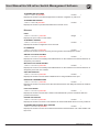
Content
1. Introduction......................................................................................................................................................... 5
2. General Advices.................................................................................................................................................. 6
3. Save Configuration............................................................................................................................................. 8
4. Overview.............................................................................................................................................................. 9
5. System Settings................................................................................................................................................ 11
5.1
5.2
5.3
5.4
5.5
5.6
5.7
5.8
5.9
General Settings................................................................................................................................................ 11
Switch Management.......................................................................................................................................... 14
Port Settings...................................................................................................................................................... 15
User Management............................................................................................................................................. 16
SNMP................................................................................................................................................................. 20
Network Discovery............................................................................................................................................. 25
Time Settings..................................................................................................................................................... 29
DHCP Relay Agent............................................................................................................................................. 38
File Transfer....................................................................................................................................................... 41
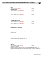
6. PROFINET.......................................................................................................................................................... 44
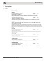
7. Redundancy....................................................................................................................................................... 45
7.1
7.2
RSTP.................................................................................................................................................................. 45
MRP................................................................................................................................................................... 49
8. VLAN................................................................................................................................................................... 56
8.1
8.2
8.3
Basic Settings.................................................................................................................................................... 56
Port Settings...................................................................................................................................................... 56
Static VLAN........................................................................................................................................................ 57
9. QoS..................................................................................................................................................................... 60
9.1
9.2
802.1p/DiffServ.................................................................................................................................................. 60
Rate Limiting...................................................................................................................................................... 62
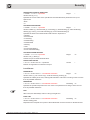
10. Security............................................................................................................................................................. 63
10.1 IP Authorized Manager....................................................................................................................................... 63
10.2 802.1x................................................................................................................................................................ 63
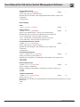
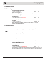
11. Link Aggregation............................................................................................................................................... 69
11.1 Basic Settings.................................................................................................................................................... 69
11.2 Interface Settings............................................................................................................................................... 69
11.3 Port Settings...................................................................................................................................................... 71
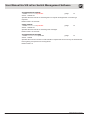
12. Multicast............................................................................................................................................................. 73
12.1 IGMP.................................................................................................................................................................. 73
12.2 VLAN Configuration........................................................................................................................................... 75
13. Alarm.................................................................................................................................................................. 79
13.1 E-Mail Alert......................................................................................................................................................... 79
13.2 SNMP Alert......................................................................................................................................................... 81
Management Software Ha-VIS mCon Series / Edition 2.4
3
User Manual Ha-VIS mCon Switch Management Software
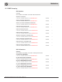
14. Diagnostics........................................................................................................................................................ 82
14.1
14.2
14.3
14.4
14.5
14.6
RMON................................................................................................................................................................ 82
Port Mirroring..................................................................................................................................................... 85
Switch History.................................................................................................................................................... 86
MAC Address Table............................................................................................................................................ 87
Light Beacon...................................................................................................................................................... 87
Ping.................................................................................................................................................................... 88
15. Statistics............................................................................................................................................................ 89
15.1 Interface............................................................................................................................................................. 89
15.2 RSTP.................................................................................................................................................................. 91
15.3 IGMP Snooping.................................................................................................................................................. 93
4
HARTING Electric GmbH
Introduction
1. Introduction
This documentation will describes how to configure the HARTING mCon 3000NG switches via
SNMP. Normally the configuration should be done via Web interface but in some cases it is also
useful to configure the switch via SNMP. The settings that will be described in this documentation
would be limited to the amount of settings that are displayed in the Web interface.
Management Software Ha-VIS mCon Series / Edition 2.4
5
User Manual Ha-VIS mCon Switch Management Software
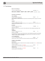
2. General Advices
Some table entries have to be created before the settings could be modified. In that case an OID
called “RowStatus” will exist. This OID handles the status of the corresponding table entry. To
create such an entry this OID has just to be set to “create and wait” (5). Afterwards the settings
of the new created entry could be modified. To activate this table entry the RowStatus has to be
set to “active” (1). When the table entry is set to “active” it is not possible to modify the settings of
this table entry, in most cases. In this case it is necessary to set the RowStatus to “not in service”
(2) and after the modifications are done back to “active” (1).
Further it is important to know that all OID extensions should have the decimal format and have
to be converted if needed. E.g. the MAC address 00:11:FC:AA:BB:CC has to be converted to
00.17.252.170.187.204.
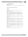
SNMP Examples
The following examples uses snmpget and snmpset from the Net-SNMP tools to illustrate the use
of authentication and privacy when accessing the managed switch.
SNMPv1 Read-Only Community
snmpget -v 1 -c public 192.168.0.126 1.3.6.1.2.1.1.5.0
SNMPv2-MIB::sysName.0 = STRING: Ha-VIS mCon 3102-AASFP
SNMPv1 Read-Write Community
snmpget -v 1 -c private 192.168.0.126 1.3.6.1.2.1.1.5.0
SNMPv2-MIB::sysName.0 = STRING: Ha-VIS mCon 3102-AASFP
snmpset -v 1 -c private 192.168.0.126 1.3.6.1.2.1.1.5.0 s “Ha-VIS mCon 3102-AASFP”
SNMPv2-MIB::sysName.0 = STRING: Ha-VIS mCon 3102-AASFP
SNMPv2c Read-Only Community
snmpget -v 2c -c public 192.168.0.126 1.3.6.1.2.1.1.5.0
SNMPv2-MIB::sysName.0 = STRING: Ha-VIS mCon 3102-AASFP
SNMPv2c Read-Write Community
snmpget -v 2c -c private 192.168.0.126 1.3.6.1.2.1.1.5.0
SNMPv2-MIB::sysName.0 = STRING: Ha-VIS mCon 3102-AASFP
snmpset -v 2c -c private 192.168.0.126 1.3.6.1.2.1.1.5.0 s “Ha-VIS mCon 3102-AASFP”
SNMPv2-MIB::sysName.0 = STRING: Ha-VIS mCon 3102-AASFP
SNMPv3
snmpget -v 3 -u harting -l authPriv -a MD5 -A 12121212 -x DES -X 12121212 192.168.0.126
1.3.6.1.2.1.1.5.0
SNMPv2-MIB::sysName.0 = STRING: Ha-VIS mCon 3102-AASFP
snmpset -v 3 -u harting -l authPriv -a MD5 -A 12121212 -x DES -X 12121212 192.168.0.126
1.3.6.1.2.1.1.5.0 s “Ha-VIS mCon 3102-AASFP”
SNMPv2-MIB::sysName.0 = STRING: Ha-VIS mCon 3102-AASFP
6
HARTING Electric GmbH
General Advices
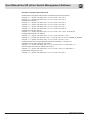
Command Description
snmpget
USAGE: snmpget [OPTIONS] AGENT OID [OID]...
OPTIONS:
-h, --help
display this help message
-v 1|2c|3
specifies SNMP version to use
SNMP Version 1 or 2c specific
-c COMMUNITY
set the community string; default password for read community: public
and for read/write community: private
SNMP Version 3 specific
-a PROTOCOL
set authentication protocol (MD5|SHA); default protocol: MD5
-A PASSPHRASE
set authentication protocol pass phrase; default passphrase: 12121212
-l LEVEL
set security level (noAuthNoPriv|authNoPriv|authPriv)
-u USER-NAME
set security name; default user: harting
-x PROTOCOL
set privacy protocol (DES|AES); default protocol: DES
-X PASSPHRASE
set privacy protocol pass phrase; default passphrase: 12121212
General communication options
-r RETRIES
set the number of retries
-t TIMEOUT
set the request timeout (in seconds)
AGENT: IP address of the switch; default: 192.168.0.126
snmpset
USAGE: snmpset [OPTIONS] AGENT OID TYPE VALUE [OID TYPE VALUE]...
OPTIONS:
-h, --help
display this help message
-v 1|2c|3
specifies SNMP version to use
SNMP Version 1 or 2c specific
-c COMMUNITY
set the community string; default password for read community: public
and for read/write community: private
SNMP Version 3 specific
-a PROTOCOL
set authentication protocol (MD5|SHA); default protocol: MD5
-A PASSPHRASE
set authentication protocol pass phrase; default passphrase: 12121212
-l LEVEL
set security level (noAuthNoPriv|authNoPriv|authPriv)
-u USER-NAME
set security name; default user: harting
-x PROTOCOL
set privacy protocol (DES|AES); default protocol: DES
-X PASSPHRASE
set privacy protocol pass phrase; default passphrase: 12121212
General communication options
-r RETRIES
set the number of retries
-t TIMEOUT
set the request timeout (in seconds)
AGENT: IP address of the switch; default: 192.168.0.126
TYPE: one of i, u, t, a, o, s, x, d, b
i: INTEGER, u: unsigned INTEGER, t: TIMETICKS, a: IPADDRESS
o: OBJID, s: STRING, x: HEX STRING, d: DECIMAL STRING, b: BITS
U: unsigned int64, I: signed int64, F: float, D: double
Management Software Ha-VIS mCon Series / Edition 2.4
7
User Manual Ha-VIS mCon Switch Management Software
3. Save Configuration
Saving the configuration persistent is one of the most important use cases. To store the
configuration the following four steps are mandatory:
Set the “Save Option” to “startup config” (4):
1.3.6.1.4.1.21108.1.81.1.10.0
integerrw
Initiate the save process (set value to “initiate” (1)):
1.3.6.1.4.1.21108.1.81.1.13.0
integerrw
Set the restore option to “restore” (2):
1.3.6.1.4.1.21108.1011.1.0
integerrw
The Default Gateway setting will not be saved in the standard configuration file. To make this
setting persistent it is necessary to set this OID:
Set the “Gateway IP address” to “Save Permanent” (1):
1.3.6.1.4.1.21108.1000.11.0
integerrw
To check the status during the saving process please use the following command:
Configuration Save Status
1.3.6.1.4.1.21108.1.81.1.14.0
integerr
Values: in Progress (1), successful (2), failed (3), not initiated (4)
8
HARTING Electric GmbH
Overview
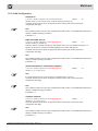
4. Overview
DEVICE NAME
1.3.6.1.2.1.1.5.0
stringrw
Shows or sets the device name. For settings of this OID see System Settings – General
Settings – General.
DEVICE CONTACT
1.3.6.1.2.1.1.4.0
stringrw
Shows or set the device contact information. For settings of this OID see System Settings –
General Settings – General.
DEVICE LOCATION
1.3.6.1.2.1.1.6.0
stringrw
Shows or set the device location information. For settings of this OID see System Settings –
General Settings – General.
DEVICE DESCRIPTION
1.3.6.1.2.1.1.1.0
Shows the device description.
stringr
PART-NO.
1.3.6.1.4.1.21108.1000.2.0
Shows the HARTING SAP order number of this device.
stringr
HARDWARE VERSION
1.3.6.1.4.1.21108.1.81.1.2.0
stringr
Shows the version number of the actual hardware implemented inside the device.
FIRMWARE VERSION
1.3.6.1.4.1.21108.1.81.1.3.0
stringr
Shows the version number of the actual running firmware release on the device.
PORT COUNT
1.3.6.1.4.1.21108.1000.1.0
integerr
Shows account of useable ports. This value is read from internal configuration file.
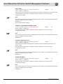
IP-ADDRESS
1.3.6.1.4.1.21108.1.27.1.5.1.2.19
ipaddrrw
Shows or set the IP address of the device. For settings of this OID see chapter System Settings
– General Settings – General.
MAC-ADDRESS
1.3.6.1.4.1.21108.1.81.1.32.0
Shows the MAC address of the device.
octetstringr
DEVICE UP TIME
1.3.6.1.2.1.1.3.0
Shows the device up time.
timeticksr
Management Software Ha-VIS mCon Series / Edition 2.4
9
User Manual Ha-VIS mCon Switch Management Software
Port Table
PORT
1.3.6.1.2.1.10.7.2.1.1.portIndex
integerr
Note
portindex from 1 up to last port, e.g. 10
JACK TYPE
1.3.6.1.4.1.21108.1000.3.1.2.portIndex
Shows information about jack type of every port.
integerr
STATUS
1.3.6.1.4.1.21108.1.27.1.4.1.4.portIndex
integerrw
Shows or set information about the administrative status of every port. For settings of this OID
see Port Settings – Basic Settings.
LINK
1.3.6.1.4.1.21108.1.27.1.4.1.5.portIndex
Shows information about the link status of every port.
integerr
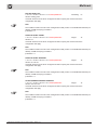
AUTO NEGOTIATION
1.3.6.1.4.1.21108.1.81.2.2.1.2.portIndex
integerrw
Shows or set information about the autonegotiation status of every port. For settings of this OID
see Port Settings – Port Control.
DATA RATE
1.3.6.1.4.1.21108.1.81.2.2.1.4.portIndex
integerrw
Shows or set information about the data rate of every port. For settings of this OID see Port
Settings – Port Control.
DUPLEX MODE
1.3.6.1.4.1.21108.1.81.2.2.1.3.portIndex
integerrw
Shows or set information about the duplex mode of every port. For settings of this OID see Port
Settings – Port Control.
10
HARTING Electric GmbH
System Settings
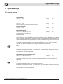
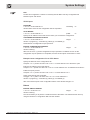
5. System Settings
5.1 General Settings
General
DEVICE NAME
1.3.6.1.2.1.1.5.0
Specify a descriptive text for the device name.
stringrw
DEVICE CONTACT
1.3.6.1.2.1.1.4.0
Specify a descriptive text for the device contact.
stringrw
DEVICE LOCATION
1.3.6.1.2.1.1.6.0
Specify a descriptive text for the device location.
stringrw
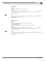
IP ADDRESS MODE
1.3.6.1.4.1.21108.1011.3.1.2.19
integerrw
Values: manual (1), dynamic (3)
IP Address Mode:
Specify the switch IP addressing mode. If Dynamic is selected in the drop-down list then the
switch is assigned a valid IP address and subnet mask during system initialisation by the DHCP
server. If Manual is selected in the drop-down list, the IP address and the subnet mask must be
entered manually. When using a DHCP server, it is also possible to assign a static IP address to
the Ethernet Switch (to its MAC address) in the settings of the DHCP server. The IP switch will
be assigned to the Ethernet Switch each time the system starts up. This makes it possible to
centralize the address administration of a large number of Ethernet switches.
Note
19 is the VLAN interface index of the management interface.
IP address parameters with Profinet: The parameters - IP Address Mode, IP Address Allocation
Protocol, IP Address, Subnet Mask and Default Gateway - cannot be altered if a connection to a
Profinet CPU is currently established!
IP ADDRESS ALLOCATION PROTOCOL
1.3.6.1.4.1.21108.1.27.1.5.1.6.19
integerrw
Values: DHCP (2)
Specify the protocol which is used to set the IP Address dynamically. The protocol DHCP is
supported.
Note
9 is the VLAN interface index of the management interface.
IP address parameters with Profinet: The parameters – IP Address Mode, IP Address Allocation
Protocol, IP Address, Subnet Mask and Default Gateway – cannot be altered if an connection to
a Profinet CPU is currently established!
Management Software Ha-VIS mCon Series / Edition 2.4
11
User Manual Ha-VIS mCon Switch Management Software
DHCP FAST ACCESS
1.3.6.1.4.1.21108.1000.21.0
integerrw
Values: enable (1), disable (2)
Sets DHCP Client to a not conform working state, that DHCP Discovers will be sent out in very
short periods.
DHCP FAST DISCOVER TIMEOUT
1.3.6.1.4.1.21108.1000.22.0
integerrw
Values: 1 - 9 sec
This option set time to wait between two DHCP discovers. It is needed for above DHCP Fast
Access.
DHCP FAST ACCESS NULL STATE TIMEOUT
1.3.6.1.4.1.21108.1000.23.0
integerrw
Values: 1 - 30 sec
This option set time to wait after four unsuccessful DHCP discovers. It is needed for above
DHCP Fast Access.
IP ADDRESS
1.3.6.1.4.1.21108.1.27.1.5.1.2.19
ipaddrrw
Precondition: IP Address Mode must be set to manual (1).
Specify the IP address of the switch. IP addresses are assigned automatically if a DHCP server
is installed.
Note
19 is the VLAN interface index of the management interface.
IP address parameters with Profinet: The parameters - IP Address Mode, IP Address Allocation
Protocol, IP Address, Subnet Mask and Default Gateway - cannot be altered if an connection to
a Profinet CPU is currently established!
SUBNET MASK
1.3.6.1.4.1.21108.1.27.1.5.1.3.19
ipaddrrw
Precondition: IP Address Mode must be set to manual (1).
Specify the subnet mask for the network. If the subnet mask is entered manually, it must be
identical with the subnet used in the network. This value is assigned automatically if you have a
DHCP server.
Note
19 is the VLAN interface index of the management interface.
IP address parameters with Profinet: The parameters - IP Address Mode, IP Address Allocation
Protocol, IP Address, Subnet Mask and Default Gateway - cannot be altered if an connection to
a Profinet CPU is currently established!
DEFAULT GATEWAY
1.3.6.1.4.1.21108.1000.10.0
Specify the default gateway for the switch.
ipaddrrw
Note
This setting will not be saved in the standard configuration file. To make this setting persistent it
is necessary to set the OID Default Gateway Saving Status: 1.3.6.1.4.1.21108.1000.11.0 to “1”.
IP address parameters with Profinet: The parameters – IP Address Mode, IP Address Allocation
Protocol, IP Address, Subnet Mask and Default Gateway – cannot be altered if an connection to
a Profinet CPU is currently established!
12
HARTING Electric GmbH
System Settings
DEFAULT GATEWAY SAVING STATUS
1.3.6.1.4.1.21108.1000.11.0
integerrw
Values: save permanent (1), save temporare (2), unsaved (3), cleared but permanent (4), act
temp but permanent (5)
Get state of default gateway IP address and optionally change to persistent save.
SWITCH BASE MAC ADDRESS
1.3.6.1.4.1.21108.1.81.1.32.0
Shows the MAC address of the device.
ipaddrr
DEFAULT VLAN IDENTIFIER
1.3.6.1.4.1.21108.1.81.1.41.0
Shows the VLAN identifier of the management port.
integerrw
CONFIGURATION SAVE STATUS
1.3.6.1.4.1.21108.1.81.1.14.0
integerr
Values: save in progress (1), save successful (2), save failed (3), not initiated (4)
Shows if the configuration has been saved.
CONFIGURATION EXPORT STATUS
1.3.6.1.4.1.21108.1.81.1.27.0
Values: in progress (1), successful (2), failed (3), not initiated (4)
Shows if the configuration has been exported to remote system.
integerr
CONFIGURATION RESTORE/IMPORT STATUS
1.3.6.1.4.1.21108.1.81.1.19.0
integerr
Values: in progress (1), successful (2), failed (3), not initiated (4)
Shows if the configuration has been restored on startup or has been imported from remote
system.
SD CARD STATUS
1.3.6.1.4.1.21108.1000.18.0
integerr
Values: system error (0), not available (1), available RO (2), available RW (3), valid
configuration RO (4), valid configuration RW (5)
Shows the current status of the SD card.
SD CARD TYPE
1.3.6.1.4.1.21108.1000.24.0
Values: None (0), MRP Client only (1), MRP Master (2).
Type of currently inserted MRP license SD card.
integer32r
SD-CARD RESTORE STATUS
1.3.6.1.4.1.21108.1000.19.0
integerr
Values: in progress (1), successful (2), checksum error (3), general error (4), not initiated (5)
Shows the status of last restore process from SD card.
HTTP PORT NUMBER
1.3.6.1.4.1.21108.1.81.1.37.0
integerrw
Shows the port through which the switch Web Interface is accessible.
Management Software Ha-VIS mCon Series / Edition 2.4
13
User Manual Ha-VIS mCon Switch Management Software
5.2 Switch Management
WEB SESSION TIMEOUT
1.3.6.1.4.1.21108.1000.14.0
Value: 60 - 36000 sec
Specify the web session timeout value in seconds.
MAXIMUM NUMBER OF WEB SESSIONS
1.3.6.1.4.1.21108.1000.15.0
Value: 1 - 10
Specify the maximum number of web session users.
integerrw
integerrw
DEFAULT/MANAGEMENT-VLAN ID
1.3.6.1.4.1.21108.1.81.1.41.0
integerrw
Before setting the management VLAN it is necessary to set the restore option to “restore factory
defaults for mgmt VLAN” (131). Afterwards the management VLAN can be modified. A reboot
should be triggered to activate the new management VLAN.
HTTP SERVER STATUS
1.3.6.1.4.1.21108.1.81.1.38.0
Values: enable (1), disable (2)
integerrw
HTTP PORT NUMBER
1.3.6.1.4.1.21108.1.81.1.37.0
integerrw
Shows the port through which the switch Web Interface is accessible.
The port to be used by the hosts to configure the switch using the web interface. A reboot is
required before this configuration will take effect.
Note
Before the HTTP port could be modified the HTTP server has to be disabled.
MULTI-FUNCTION BUTTON
1.3.6.1.4.1.21108.1000.13.0
Values: enable (1), disable (2)
Enables or disables the functionality of the multi-function button.
TELNET ACCESS
1.3.6.1.4.1.21108.1000.20.0
Values: enable (1), disable (2)
Enables or disables the Telnet/CLI-Access.
14
integerrw
integerrw
HARTING Electric GmbH
System Settings
5.3 Port Settings
Basic Settings
PORT
1.3.6.1.2.1.10.7.2.1.1.portIndex
Specifies the port number.
integerr
ADMIN STATE
1.3.6.1.4.1.21108.1.27.1.4.1.4.portIndex
integerrw
Values: up (1), down (2)
Select the desired state of the port. A port can be either enabled (up) or disabled (down).
LINK STATUS
1.3.6.1.4.1.21108.1.27.1.4.1.5.portIndex
Values: up (1), down (2)
Displays the port status.
Integerr
Port Control
PORT
1.3.6.1.2.1.10.7.2.1.1.portIndex
Specifies the port number.
integerr
AUTONEGOTIATION
1.3.6.1.4.1.21108.1.81.2.2.1.2.portIndex
integerrw
Values: auto (1), no negotiation (2)
Select whether auto-negotiation is disabled or enabled. Auto-negotiation is a function which
enables the participating interfaces to automatically determine the best possible transmission
parameters. The auto-negotiation function can either be activated (enable) or deactivated
(disable).
DUPLEX
1.3.6.1.4.1.21108.1.81.2.2.1.3.portIndex
integerrw
Values: full (1), half (2)
Select the data transmission mode for the respective port from the drop-down list. Half means
that data flows in only one direction via the port at a given time; Full enables data to flow in both
directions simultaneously.
SPEED
1.3.6.1.4.1.21108.1.81.2.2.1.4.portIndex
integerrw
Values: 10Mbit/s (1), 100Mbit/s (2), 1Gbit/s (3)
Select the data transmission rates for the port from the drop-down list: 10 Mbit/s, 100 Mbit/s or
1 Gbit/s, depending on the type of port interface.
FLOW CONTROL
1.3.6.1.4.1.21108.1.81.2.2.1.5.portIndex
integerrw
Values: enable (1), disable (2)
Select if flow control is activated (enable) or deactivated (disable). If enabled, the port sends out
pause frames when the buffer capacity reaches a certain limit.
Management Software Ha-VIS mCon Series / Edition 2.4
15
User Manual Ha-VIS mCon Switch Management Software
AUTOCROSSING
1.3.6.1.4.1.21108.1011.4.1.2.portIndex
integerrw
Values: auto (1), mdi (2), mdix (3)
Select the autocrossing mode for the respective port.
• Auto – Makes automatic modification of the transmitting and receiving line of a port possible.
• MDI – No modification of the transmitting and receiving line of a port.
• MDIX – Crosses transmitting and receiving lines of a port.
5.4 User Management
User Management
TOTAL NUMBER OF USERS
1.3.6.1.4.1.21108.2.2.70.1.1.0
The total number of users with created account.
unsignedr
CURRENTLY LOGGED ON USERS
1.3.6.1.4.1.21108.2.2.70.1.2.0
unsignedr
The total number of users who have currently logged in via different sessions will be tracked
here.
CREATE USER
To create a new user account it is necessary to know a username and password of an account
with administrative privileges. With this account it is possible to create new user.
ROWSTATUS
1.3.6.1.4.1.21108.2.2.70.2.1.1.8.noOfCharOfUser.user.noOfCharOfAuthStr.authStr
integerrw
Values: active (1), not in service (2), create and wait (5), destroy (6)
The part authString of the OID is built up as follows: currentUser.colon.currentUserPassword
Reading this OID will not show the real authString but only a dummy string:
“authenticationstring”
Note
The user and the authString must be converted to decimal ASCII (see example below).
USER PASSWORD
1.3.6.1.4.1.21108.2.2.70.2.1.1.3.noOfCharOfUser.user.noOfCharOfAuthStr.authStr
stringrw
Note
Password must have at least 6 characters.
CONFIRM PASSWORD
1.3.6.1.4.1.21108.2.2.70.2.1.1.9.noOfCharOfUser.user.noOfCharOfAuthStr.authStr
stringrw
Confirm the user password.
PRIVILEGE
1.3.6.1.4.1.21108.2.2.70.2.1.1.4.noOfCharOfUser.user.noOfCharOfAuthStr.authStr
unsignedrw
Set privilege: 15 = admin, 0 = guest
16
HARTING Electric GmbH
System Settings
Example: Create New User
Create new User entry:
Number of characters inside “User Name” string: 4
User name: root
converted to decimal ASCII: 114.111.111.116
Number of characters inside the “Authentication String”: 13
Authentication String: admin:harting
converted to decimal ASCII: 97.100.109.105.110.58.104.97.114.116.105.110.103
Password: 123456
Create the user “root” as the logon user “admin” with password “harting”:
snmpset -v 2c -c private 192.168.0.126 1.3.6.1.4.1.21108.2.2.70.2.1.1.8. 4.114.111.111.116.13.9
7.100.109.105.110.58.104.97.114.116.105.110.103 i 5
Set password 123456 for new user root:
snmpset -v 2c -c private 192.168.0.126 1.3.6.1.4.1.21108.2.2.70.2.1.1.3. 4.114.111.111.116.13.9
7.100.109.105.110.58.104.97.114.116.105.110.103 s 123456
Confirm password 123456 for new user root:
snmpset -v 2c -c private 192.168.0.126 1.3.6.1.4.1.21108.2.2.70.2.1.1.9. 4.114.111.111.116.13.9
7.100.109.105.110.58.104.97.114.116.105.110.103 s 123456
Set privilege level for new user root:
snmpset -v 2c -c private 192.168.0.126 1.3.6.1.4.1.21108.2.2.70.2.1.1.4. 4.114.111.111.116.13.9
7.100.109.105.110.58.104.97.114.116.105.110.103 u 15
Activate new user root:
snmpset -v 2c -c private 192.168.0.126 1.3.6.1.4.1.21108.2.2.70.2.1.1.8. 4.114.111.111.116.13.9
7.100.109.105.110.58.104.97.114.116.105.110.103 i 1
Management Software Ha-VIS mCon Series / Edition 2.4
17
User Manual Ha-VIS mCon Switch Management Software
Note
Find here the ASCII table:
Dez Hex
0
18
Okt
0x00 000
ASCII
Dez Hex
NUL
32
Okt
0x20 040
ASCII
Dez Hex
SP
64
Okt
0x40 100
ASCII
Dez Hex
@
96
Okt
ASCII
0x60 140 `
1
0x01 001
SOH
33
0x21 041
!
65
0x41 101
A
97
0x61 141
a
2
0x02 002
STX
34
0x22 042
“
66
0x42 102
B
98
0x62 142
b
3
0x03 003
ETX
35
0x23 043
#
67
0x43 103
C
99
0x63 143
c
4
0x04 004
EOT
36
0x24 044
$
68
0x44 104
D
100 0x64 144 d
5
0x05 005
ENQ
37
0x25 045
%
69
0x45 105
E
101 0x65 145
e
6
0x06 006
ACK
38
0x26 046
&
70
0x46 106
F
102 0x66 146
f
7
0x07 007
BEL
39
0x27 047
“
71
0x47 107
G
103 0x67 147 g
8
0x08 010
BS
40
0x28 050
(
72
0x48 110
H
104 0x68 150
h
9
0x09 011
HT
41
0x29 051
73
0x49 111
I
105 0x69 151
i
j
10
0x0A 012
LF
42
0x2A 052
*
74
0x4A 112
J
106 0x6A 152
11
0x0B 013
VT
43
0x2B 053
+
75
0x4B 113
K
107 0x6B 153 k
12
0x0C 014
FF
44
0x2C 054 ,
76
0x4C 114
L
108 0x6C 154
l
m
13
0x0D 015
CR
45
0x2D 055
-
77
0x4D 115
M
109 0x6D 155
14
0x0E 016
SO
46
0x2E 056
.
78
0x4E 116
N
110 0x6E 156 n
15
0x0F 017
SI
47
0x2F 057
/
79
0x4F 117
O
111 0x6F 157
o
p
16
0x10 020
DLE
48
0x30 060
0
80
0x50 120
P
112 0x70 160
17
0x11 021
DC1
49
0x31 061
1
81
0x51 121
Q
113 0x71 161 q
18
0x12 022
DC2
50
0x32 062
2
82
0x52 122
R
114 0x72 162
r
19
0x13 023
DC3
51
0x33 063
3
83
0x53 123
S
115 0x73 163
s
20
0x14 024
DC4
52
0x34 064
4
84
0x54 124
T
116 0x74 164
t
21
0x15 025
NAK
53
0x35 065
5
85
0x55 125
U
117 0x75 165 u
22
0x16 026
SYN
54
0x36 066
6
86
0x56 126
V
118 0x76 166
v
23
0x17 027
ETB
55
0x37 067
7
87
0x57 127
W
119 0x77 167
w
24
0x18 030
CAN
56
0x38 070
8
88
0x58 130
X
120 0x78 170
x
25
0x19 031
EM
57
0x39 071
9
89
0x59 131
Y
121 0x79 171
y
26
0x1A 032
SUB
58
0x3A 072
:
90
0x5A 132
Z
122 0x7A 172
z
27
0x1B 033
ESC
59
0x3B 073
;
91
0x5B 133
[
123 0x7B 173
{
28
0x1C 034
FS
60
0x3C 074
<
92
0x5C 134
\
124 0x7C 174
|
29
0x1D 035
GS
61
0x3D 075 =
93
0x5D 135
]
125 0x7D 175
}
30
0x1E 036
RS
62
0x3E 076
>
94
0x5E 136 ^
126 0x7E 176
~
31
0x1F 037
US
63
0x3F 077
?
95
0x5F 137
127 0x7F 177
DEL
_
HARTING Electric GmbH
System Settings
Change Password
To change the password of a user account it is necessary to know the username and password of
an account with administrative privileges. Via this account it is possible to change the password
of any other account.
To change the password the RowStatus has to be set to “not in service”.
Set and confirm the new password and set the RowStatus to active again.
ROWSTATUS
1.3.6.1.4.1.21108.2.2.70.2.1.1.8.noOfCharOfUser.user.noOfCharOfAuthStr.authStrint
rw
Values: active (1), not in service (2), create and wait (5), destroy (6)
The part authString of the OID is built up as follows: currentUser.colon.currentUserPassword
After reading this OID, it will not show the real authString. It will show a dummy string:
"authenticationstring"
USER PASSWORD
1.3.6.1.4.1.21108.2.2.70.2.1.1.3.noOfCharOfUser.user.noOfCharOfAuthStr.authStrstring rw
Password must have at least 6 characters.
CONFIRM PASSWORD
1.3.6.1.4.1.21108.2.2.70.2.1.1.9.noOfCharOfUser.user.noOfCharOfAuthStr.authStrstring rw
Confirm the user password.
Example: Change User Password
Number of Character inside “User Name” String: 4
User name: root
converted to decimal ASCII: 114.111.111.116
Number of Character inside the “Authentication String”: 13
Authentication String: admin:harting
converted to decimal ASCII: 97.100.109.105.110.58.104.97.114.116.105.110.103
Old password: 123456
New password: 13131313
Set the user “root” inactive (not in service):
snmpset -v 2c -c private 192.168.0.126 1.3.6.1.4.1.21108.2.2.70.2.1.1.8. 4.114.111.111.116.13.9
7.100.109.105.110.58.104.97.114.116.105.110.103 i 2
Set Password 13131313 for user root:
snmpset -v 2c -c private 192.168.0.126 1.3.6.1.4.1.21108.2.2.70.2.1.1.3. 4.114.111.111.116.13.9
7.100.109.105.110.58.104.97.114.116.105.110.103 s 13131313
Confirm Password 13131313 for user root:
snmpset -v 2c -c private 192.168.0.126 1.3.6.1.4.1.21108.2.2.70.2.1.1.9. 4.114.111.111.116.13.9
7.100.109.105.110.58.104.97.114.116.105.110.103 s 13131313
Set privilege level for new user root:
Activate user root:
snmpset -v 2c -c private 192.168.0.126 1.3.6.1.4.1.21108.2.2.70.2.1.1.8. 4.114.111.111.116.13.9
7.100.109.105.110.58.104.97.114.116.105.110.103 i 1
Management Software Ha-VIS mCon Series / Edition 2.4
19
User Manual Ha-VIS mCon Switch Management Software
5.5 SNMP
The SNMP settings consist of several parts based on the security enhancements of SNMPv3.
One is the User-based Security Model (USM) and the other is the View Access Control Model
(VACM). To configure a working access through SNMPv1/2c and v3 to the switch it is necessary
to configure the community-, the user-, the group-, the access- and the view-tree-family-table.
The order the tables have to be configured is very important because they depend on each other.
The names that are used in the OIDs have to be converted to decimal ASCII numbers (Example:
“public” = 112.117.98.108.105.99)
To modify a table entry it is often necessary to deactivate the RowStatus of that entry. To deactivate
it simply set the RowStatus to deactivate (2). To remove a table entry just set the RowStatus to
destroy (6). Here it is also important to regard the order.
To get the HARTING factory default, these 5 tables have to be configured as follows:
Create Default SNMP v1/v2c Access
Create default Read Community
Note
“public” and “private” are the recommended names for the default SNMP communities.
“TrapProfile1” and “TrapProfile2” are mandatory names because otherwise the SNMP traps
won't work.
CREATE COMMUNITY
1.3.6.1.6.3.18.1.1.1.8.public = integer: 5
SET COMMUNITYNAME
1.3.6.1.6.3.18.1.1.1.2.public = string: public
SET SECURITYNAME
1.3.6.1.6.3.18.1.1.1.3.public = string: TrapProfile1
Create new Read/Write Community
CREATE COMMUNITY
1.3.6.1.6.3.18.1.1.1.8.private = integer: 5
SET COMMUNITYNAME
1.3.6.1.6.3.18.1.1.1.2.private = string: private
SET SECURITYNAME
1.3.6.1.6.3.18.1.1.1.3.private = string: TrapProfile2
Create defaults for Read Community
Note
“TrapProfile1” is the name that should be used here.
20
HARTING Electric GmbH
System Settings
Group table settings
CREATE NEW GROUP FOR V1
1.3.6.1.6.3.16.1.2.1.5.1.NoOfChar.TrapProfile1 = integer: 5
ACTIVATE NEW GROUP FOR V1
1.3.6.1.6.3.16.1.2.1.5.1.NoOfChar.TrapProfile1 = integer: 1
SET GROUPNAME FOR V1
1.3.6.1.6.3.16.1.2.1.3.1.NoOfChar.TrapProfile1 = string: TrapProfile1
CREATE NEW GROUP FOR V2C
1.3.6.1.6.3.16.1.2.1.5.2.NoOfChar.TrapProfile1 = integer: 5
ACTIVATE NEW GROUP FOR V2C
1.3.6.1.6.3.16.1.2.1.5.2.NoOfChar.TrapProfile1 = integer: 1
SET GROUPNAME FOR V2C
1.3.6.1.6.3.16.1.2.1.3.2.NoOfChar.TrapProfile1 = string: TrapProfile1
Access table settings
CREATE NEW ACCESS LEVEL FOR V1
1.3.6.1.6.3.16.1.4.1.9.NoOfChar.TrapProfile1.0.1.1 = integer: 5
CREATE NEW ACCESS LEVEL FOR V2C
1.3.6.1.6.3.16.1.4.1.9.NoOfChar.TrapProfile1.0.2.1 = integer: 5
SET READVIEW NAME FOR V1
1.3.6.1.6.3.16.1.4.1.5.NoOfChar.TrapProfile1.0.1.1 = string: TrapProfile1
SET READVIEW NAME FOR V2C
1.3.6.1.6.3.16.1.4.1.5.NoOfChar.TrapProfile1.0.2.1 = string: TrapProfile1
ACIVATE ACCESS LEVEL FOR V1
1.3.6.1.6.3.16.1.4.1.9.NoOfChar.TrapProfile1.0.1.1 = integer: 1
ACTIVATE ACCESS LEVEL FOR V2C
1.3.6.1.6.3.16.1.4.1.9.NoOfChar.TrapProfile1.0.2.1 = integer: 1
View Tree Family table settings
CREATE NEW READ VIEW
1.3.6.1.6.3.16.1.5.2.1.6.NoOfChar.TrapProfile1.1.1 = integer: 5
ACTIVATE READ VIEW
1.3.6.1.6.3.16.1.5.2.1.6.NoOfChar.TrapProfile1.1.1 = integer: 1
Create defaults for Read/Write Community
Note
“TrapProfile2” is the name that should be used here.
Management Software Ha-VIS mCon Series / Edition 2.4
21
User Manual Ha-VIS mCon Switch Management Software
Group table settings
CREATE NEW GROUP FOR V1
1.3.6.1.6.3.16.1.2.1.5.1.NoOfChar.TrapProfile2 = integer: 5
ACTIVATE NEW GROUP FOR V1
1.3.6.1.6.3.16.1.2.1.5.1.NoOfChar.TrapProfile2 = integer: 1
SET GROUPNAME FOR V1
1.3.6.1.6.3.16.1.2.1.3.1.NoOfChar.TrapProfile2 = string: TrapProfile2
CREATE NEW GROUP FOR V2C
1.3.6.1.6.3.16.1.2.1.5.2.NoOfChar.TrapProfile2 = integer: 5
ACTIVATE NEW GROUP FOR V2C
1.3.6.1.6.3.16.1.2.1.5.2.NoOfChar.TrapProfile2 = integer: 1
SET GROUPNAME FOR V2C
1.3.6.1.6.3.16.1.2.1.3.2.NoOfChar.TrapProfile2 = string: TrapProfile2
Access table settings
CREATE NEW ACCESS LEVEL FOR V1
1.3.6.1.6.3.16.1.4.1.9.NoOfChar.TrapProfile2.0.1.1 = integer: 5
CREATE NEW ACCESS LEVEL FOR V2C
1.3.6.1.6.3.16.1.4.1.9.NoOfChar.TrapProfile2.0.2.1 = integer: 5
SET READVIEW NAME FOR V1
1.3.6.1.6.3.16.1.4.1.5.NoOfChar.TrapProfile2.0.1.1 = string: TrapProfile2
SET READVIEW NAME FOR V2C
1.3.6.1.6.3.16.1.4.1.5.NoOfChar.TrapProfile2.0.2.1 = string: TrapProfile2
SET WRITEVIEW NAME FOR V1
1.3.6.1.6.3.16.1.4.1.6.NoOfChar.TrapProfile2.0.1.1 = string: TrapProfile2
SET WRITEVIEW NAME FOR V2C
1.3.6.1.6.3.16.1.4.1.6.NoOfChar.TrapProfile2.0.2.1 = string: TrapProfile2
ACIVATE ACCESS LEVEL FOR V1
1.3.6.1.6.3.16.1.4.1.9.NoOfChar.TrapProfile2.0.1.1 = integer: 1
ACTIVATE ACCESS LEVEL FOR V2C
1.3.6.1.6.3.16.1.4.1.9.NoOfChar.TrapProfile2.0.2.1 = integer: 1
View Tree Family table settings
CREATE NEW READ/WRITE VIEW
1.3.6.1.6.3.16.1.5.2.1.6.NoOfChar.TrapProfile2.1.1 = integer: 5
ACTIVATE READ/WRITE VIEW
1.3.6.1.6.3.16.1.5.2.1.6.NoOfChar.TrapProfile2.1.1 = integer: 1
22
HARTING Electric GmbH
System Settings
Create Default SNMPv3 Access
Username: “harting”
Note
You can use “harting” also for Groupname and ReadWriteViewName
User table settings
CREATE NEW USER
1.3.6.1.6.3.15.1.2.2.1.13.7.128.0.8.28.4.70.83.NoOfChar.UserName = integer: 5
SET AUTHENTICATION PROTOCOL TO MD5
none (1.3.6.1.6.3.10.1.1.1), MD5 (1.3.6.1.6.3.10.1.1.2), SHA (1.3.6.1.6.3.10.1.1.3)
1.3.6.1.6.3.15.1.2.2.1.5.7.128.0.8.28.4.70.83.NoOfChar.UserName = OID:1.3.6.1.6.3.10.1.1.2
SET PASSWD FOR AUTH PROTOCOL
1.3.6.1.6.3.15.1.2.2.1.6.7.128.0.8.28.4.70.83.NoOfChar.UserName = string: password
SET PRIVACY PROTOCOL TO DES
none (1.3.6.1.6.3.10.1.2.1), DES (1.3.6.1.6.3.10.1.2.2)
1.3.6.1.6.3.15.1.2.2.1.8.7.128.0.8.28.4.70.83.NoOfChar.UserName = OID:1.3.6.1.6.3.10.1.2.2
SET PASSWD FOR PRIVACY PROTOCOL
1.3.6.1.6.3.15.1.2.2.1.9.7.128.0.8.28.4.70.83.NoOfChar.UserName = string: password
ACTIVATE NEW USER
1.3.6.1.6.3.15.1.2.2.1.13.7.128.0.8.28.4.70.83.NoOfChar.UserName = integer: 1
Group table settings
CREATE NEW GROUP
1.3.6.1.6.3.16.1.2.1.5.3.NoOfChar.UserName = integer: 5
ACTIVATE NEW GROUP
1.3.6.1.6.3.16.1.2.1.5.3.NoOfChar.UserName = integer: 1
SET GROUPNAME
1.3.6.1.6.3.16.1.2.1.3.3.NoOfChar.UserName = string: GroupName
Access table settings
CREATE NEW ACCESS LEVEL FOR
noAuthNoPriv (1), AuthNoPriv (2), AuthPriv (3)
1.3.6.1.6.3.16.1.4.1.9.NoOfChar.GroupName.0.3.3 = integer: 5
SET READVIEW NAME FOR CORRESPONDING ACCESS LEVEL
1.3.6.1.6.3.16.1.4.1.5.NoOfChar.GroupName.0.3.3 = string: ReadWriteViewName
SET WRITEVIEW NAME NAME FOR CORRESPONDING ACCESS LEVEL
1.3.6.1.6.3.16.1.4.1.6.NoOfChar.GroupName.0.3.3= string: ReadWriteViewName
ACTIVATE ACCESS LEVEL
1.3.6.1.6.3.16.1.4.1.9.NoOfChar.GroupName.0.3.3 = integer: 1
Management Software Ha-VIS mCon Series / Edition 2.4
23
User Manual Ha-VIS mCon Switch Management Software
View Tree Family table settings
CREATE NEW READ/WRITE VIEW
1.3.6.1.6.3.16.1.5.2.1.6.NoOfChar.ReadWriteViewName.1.1 = integer: 5
ACTIVATE READ/WRITE VIEW
1.3.6.1.6.3.16.1.5.2.1.6.NoOfChar.ReadWriteViewName.1.1 = integer: 1
SNMP Example 1: Change SNMP v1/2c Read and Read/Write Community Password:
Converted to decimal ASCII:
Public=112.117.98.108.105.99
Private= 112.114.105.118.97.116.101
Read =114.101.97.100
Write = 119.114.105.116.101
Change Read/Write Community Access via SNMPv1:
Change Read/Write access community password to “write”:
snmpset -v1 -c private 192.168.0.126 1.3.6.1.6.3.18.1.1.1.8.119.114.105.116.101 i 5
snmpset -v1 -c private 192.168.0.126 1.3.6.1.6.3.18.1.1.1.2.119.114.105.116.101 s write
snmpset -v1 -c private 192.168.0.126 1.3.6.1.6.3.18.1.1.1.3.119.114.105.116.101 s TrapProfile2
snmpset -v1 -c private 192.168.0.126 1.3.6.1.6.3.18.1.1.1.8.119.114.105.116.101 i 1
Change read access community password to “read”:
snmpset -v1 -c private 192.168.0.126 1.3.6.1.6.3.18.1.1.1.8.114.101.97.100 i 5
snmpset -v1 -c private 192.168.0.126 1.3.6.1.6.3.18.1.1.1.2.114.101.97.100 s read
snmpset -v1 -c private 192.168.0.126 1.3.6.1.6.3.18.1.1.1.3.114.101.97.100 s TrapProfile1
snmpset -v1 -c private 192.168.0.126 1.3.6.1.6.3.18.1.1.1.8.114.101.97.100 i 1
Delete old read access community password “public”:
snmpset -v1 -c write 192.168.0.126 1.3.6.1.6.3.18.1.1.1.8.112.117.98.108.105.99 i 6
Delete old read/write access community password “private”:
snmpset -v1 -c write 192.168.0.126 1.3.6.1.6.3.18.1.1.1.8.112.114.105.118.97.116.101 i 6
SNMP Example 2: Disable SNMP v1/2c
Converted to decimal ASCII:
Public=112.117.98.108.105.99
Private= 112.114.105.118.97.116.101
Delete old read access community password “public”:
snmpset -v1 -c private 192.168.0.126 1.3.6.1.6.3.18.1.1.1.8.112.117.98.108.105.99 i 6
Delete old read/write access community password “private”:
snmpset -v1 -c private 192.168.0.126 1.3.6.1.6.3.18.1.1.1.8.112.114.105.118.97.116.101 i 6
24
HARTING Electric GmbH
System Settings
5.6 Network Discovery
LLDP Settings
ACTIVATE LLDP
1.3.6.1.4.1.21108.1.158.1.2.0
integerrw
Values: enable (1), disable (2)
Select whether to disable or enable LLDP on the switch globally on the switch.
CHASSIS ID SUBTYPE
1.3.6.1.4.1.21108.1.158.2.1.0
integerrw
Values: chassis comp (1), interface alias (2), port comp (3), MAC address (4), network address
(5), interface name (6), local (7)
Select the Chassis ID Subtype which should be written in the LLDP packets.
CHASSIS ID
1.3.6.1.4.1.21108.1.158.2.2.0
octetstringr/rw
Depending on the Chassis ID Subtype the value will be set automatically or could be set
manually.
Select the Chassis ID which should be written in the LLDP packets.
TRANSMIT INTERVAL
1.0.8802.1.1.2.1.1.1.0
integerrw
Values: 5 - 32768 sec
The interval at which LLDP frames are transmitted on behalf of this LLDP agent. The default
value for the Transmit Interval is 30 seconds.
TTL MULTIPLIER
1.0.8802.1.1.2.1.1.2.0
integerrw
Values: 2-10
The time-to-live value expressed as a multiple of the transmit interval.
SEND IP ADDRESS
1.0.8802.1.1.2.1.1.7.1.1.1.4.ipAddr
octetstringrw
The OID extension 1.4.ipAddr indicates the context ID (1) the IP address version (4) followed by
the IP address (e.g.: 192.168.0.126).
Port Table
PORT
1.3.6.1.2.1.10.7.2.1.1.portIndex
integerr
PORT ID SUBTYPE
1.3.6.1.4.1.21108.1.158.2.3.1.1.portIndex
integerrw
Values: ifalias (1), portcomp (2), macaddr (3), nwaddr (4), ifname (5), agentcircuitid (6), local (7)
PORT ID
1.3.6.1.4.1.21108.1.158.2.3.1.2.portIndex
octetstringr/rw
Depending on the Port ID Subtype the value will be readonly or read-write.
Management Software Ha-VIS mCon Series / Edition 2.4
25
User Manual Ha-VIS mCon Switch Management Software
LLDP Connections
LLDP NEIGHBOUR CHASSIS ID SUBTYPE
1.0.8802.1.1.2.1.4.1.1.4.randomID.localPortIndex.incrementingIndex
integerr
The OID extension randomID.localPortIndex.incrementingIndex indicates a randomID (e.g.:
32901000), the local port (e.g. 3) and an incrementing index (e.g. 1).
Values: chassis component (1), interface alias (2), port component (3), MAC address (4),
network address (5), interface name (6), local (7)
The type of encoding used to identify the chassis associated with the neighbour system.
LLDP NEIGHBOUR CHASSIS ID
1.0.8802.1.1.2.1.4.1.1.5.randomID.localPortIndex.incrementingIndex
octetstringr
The OID extension randomID.localPortIndex.incrementingIndex indicates a randomID (e.g.:
32901000), the local port (e.g. 3) and an incrementing index (e.g. 1).
The string value used to identify the chassis component associated with the neighbour system.
LLDP NEIGHBOUR PORT ID SUBTYPE
1.0.8802.1.1.2.1.4.1.1.6.randomID.localPortIndex.incrementingIndex
integerr
The OID extension randomID.localPortIndex.incrementingIndex indicates a randomID (e.g.:
32901000), the local port (e.g. 3) and an incrementing index (e.g. 1).
Values: interface alias (1), port component (2), MAC address (3), network address (4), interface
name (5), agent Circuit ID (6), local (7)
The type of port identifier encoding used in the associated “LLDP Neighbour Port ID” object.
LLDP NEIGHBOUR PORT ID
1.0.8802.1.1.2.1.4.1.1.7.randomID.localPortIndex.incrementingIndex
octetstringr
The OID extension randomID.localPortIndex.incrementingIndex indicates a randomID (e.g.:
32901000), the local port (e.g. 3) and an incrementing index (e.g. 1).
The string value used to identify the port component associated with the neighbour system.
LLDP NEIGHBOUR PORT DESCRIPTION
1.0.8802.1.1.2.1.4.1.1.8.randomID.localPortIndex.incrementingIndex
octetstringr
The OID extension randomID.localPortIndex.incrementingIndex indicates a randomID (e.g.:
32901000), the local port (e.g. 3) and an incrementing index (e.g. 1).
The string value used to identify the description of the given port associated with the neighbour system.
LLDP NEIGHBOUR SYSTEM NAME
1.0.8802.1.1.2.1.4.1.1.9.randomID.localPortIndex.incrementingIndex
octetstringr
The OID extension randomID.localPortIndex.incrementingIndex indicates a randomID (e.g.:
32901000), the local port (e.g. 3) and an incrementing index (e.g. 1).
The string value used to identify the system name of the neighbour system.
LLDP NEIGHBOUR SYSTEM DESCRIPTION
1.0.8802.1.1.2.1.4.1.1.10.randomID.localPortIndex.incrementingIndex
octetstringr
The OID extension randomID.localPortIndex.incrementingIndex indicates a randomID (e.g.:
32901000), the local port (e.g. 3) and an incrementing index (e.g. 1).
The string value used to identify the system description of the neighbour system.
LLDP NEIGHBOUR SYSTEM CAPABILITIES SUPPORTED
1.0.8802.1.1.2.1.4.1.1.11.randomID.localPortIndex.incrementingIndex
bitstringr
The OID extension randomID.localPortIndex.incrementingIndex indicates a randomID (e.g.:
32901000), the local port (e.g. 3) and an incrementing index (e.g. 1).
Values: other (0), repeater (1), bridge (2), WLAN access point (3), router (4), telephone (5),
docsis cable device (6), station only (7)
The bitmap value used to identify which system capabilities are supported on the neighbour
system.
26
HARTING Electric GmbH
System Settings
LLDP NEIGHBOUR SYSTEM CAPABILITIES ENABLED
1.0.8802.1.1.2.1.4.1.1.12.randomID.localPortIndex.incrementingIndex
bitstringr
The OID extension randomID.localPortIndex.incrementingIndex indicates a randomID (e.g.:
32901000), the local port (e.g. 3) and an incrementing index (e.g. 1).
Values: other (0), repeater (1), bridge (2), WLAN access point (3), router (4), telephone (5),
docsis cable device (6), station only (7)
The bitmap value used to identify which system capabilities are enabled on the neighbour
system.
LLDP NEIGHBOUR MANAGEMENT ADDRESS INTERFACE SUBTYPE
1.0.8802.1.1.2.1.4.2.1.3.randomID.localPortIndex.incrementingIndex.1.4.ipAddrinteger
r
The OID extension randomID.localPortIndex.incrementingIndex.1.4.ipAddr indicates a
randomID (e.g.: 32901000), the local port (e.g. 3) and an incrementing index (e.g. 1), the
context ID (1), the IP version (IPv4) and the neighbour IP address (e.g.: 192.168.0.126).
Values: unknown (1), interface index (2), system port number (3)
The value that identifies the interface numbering method used for defining the interface number,
associated with the neighbour system.
LLDP NEIGHBOUR MANAGEMENT ADDRESS INTERFACE ID
1.0.8802.1.1.2.1.4.2.1.4.randomID.localPortIndex.incrementingIndex.1.4.ipAddrinteger
r
The OID extension randomID.localPortIndex.incrementingIndex.1.4.ipAddr indicates a
randomID (e.g.: 32901000), the local port (e.g. 3) and an incrementing index (e.g. 1), the
context ID (1), the IP version (IPv4) and the neighbour IP address (e.g.: 192.168.0.126).
The integer value used to identify the interface number regarding the management address
component associated with the neighbour system, e.g. 19 for Management Interface VLAN1.
LLDP NEIGHBOUR MANAGEMENT ADDRESS OID
1.0.8802.1.1.2.1.4.2.1.5.randomID.localPortIndex.incrementingIndex.1.4.ipAddrOID
r
The OID extension randomID.localPortIndex.incrementingIndex.1.4.ipAddr indicates a
randomID (e.g.: 32901000), the local port (e.g. 3) and an incrementing index (e.g. 1), the
context ID (1), the IP version (IPv4) and the neighbour IP address (e.g.: 192.168.0.126).
The OID value used to identify the type of hardware component or protocol entity associated
with the management address advertised by the neighbour system agent.
Management Software Ha-VIS mCon Series / Edition 2.4
27
User Manual Ha-VIS mCon Switch Management Software
Advanced LLDP Settings
PORT
1.3.6.1.2.1.10.7.2.1.1.portIndex
integerr
LLDP PORT SETTINGS
1.0.8802.1.1.2.1.1.6.1.2.portIndex
Integerrw
Values: TX only (1), RX only (2), TX and RX (3), disabled (4)
TX only - The LLDP agent will transmit LLDP frames on this port and it will not store any
information about the neighbour systems connected.
RX only - The LLDP agent will receive, but it will not transmit LLDP frames on this port.
TX and RX - The LLDP agent will transmit and receive LLDP frames on this port.
Disabled - The LLDP agent will not transmit or receive LLDP frames on this port.
Example: LLDP Configuration
Activate LLDP:
snmpset -v 2c -c private 192.168.0.126 1.3.6.1.4.1.21108.158.1.2.0 i 1
Set Send IP Address:
snmpset -v 2c -c private 192.168.0.126 1.0.8802.1.1.2.1.1.7.1.1.1.4.192.168.0.126 x FFFFFFFF
Set Transmit Interval to 5 sec:
snmpset -v 2c -c private 192.168.0.126 1.0.8802.1.1.2.1.1.1.0 i 5
Set TTL Multiplier to 2:
snmpset -v 2c -c private 192.168.0.126 1.0.8802.1.1.2.1.1.2.0 i 2
Set port ID at port 7 to MAC address:
snmpset -v 2c -c private 192.168.0.126 1.3.6.1.4.1.21108.158.2.3.1.1.7 i 3
Set port ID at port 8 to custom “Port8”:
snmpset -v 2c -c private 192.168.0.126 1.3.6.1.4.1.21108.158.2.3.1.1.8 i 7
snmpset -v 2c -c private 192.168.0.126 1.3.6.1.4.1.21108.158.2.3.1.2.8 s “Port8”
Set ports 9 and 10 disabled for LLDP:
snmpset -v 2c -c private 192.168.0.126 1.0.8802.1.1.2.1.1.6.1.2.9 i 4
snmpset -v 2c -c private 192.168.0.126 1.0.8802.1.1.2.1.1.6.1.2.10 i 4
28
HARTING Electric GmbH
System Settings
5.7 Time Settings
Manual Time Settings
1.3.6.1.4.1.21108.1.81.1.34.0
octetstringrw
Value: <Hour>”:”<Minute>”:”<Second>” “<Day>” “<Month>” “<Year>
Read-Output: <WeekDay>” ”<Month>” ”<Day>” “<Hour>”:”<Minute>”:”<Second>” “<Year>
Automatic Time Settings
AUTO UPDATE
1.3.6.1.4.1.21108.1.149.1.1.3.0
integerrw
Values: enable (1), disabled (0)
Check this box in order to receive the system time automatically with the support of an SNTP
server.
STATUS
1.3.6.1.4.1.21108.1.149.1.1.15.0
integerr
Values: not running (1), not synchronized (2), none configured (3), sync to local (4), sync to
remote server (5), unknown (99)
INTERVAL
1.3.6.1.4.1.21108.1.149.1.2.2.0
unsignedrw
Values: 64-16284 sec
Specify the period of time in seconds. The system time is then updated periodically at this
interval.
TIMEZONE
1.3.6.1.4.1.21108.1.149.1.1.11.0
stringrw
Values: (+/-)HH:MM
To set the system time zone with respect to UTC. ie plus indicates forward time zone (ahead
of UTC Time e.g.: +05:30) and minus indicates backward time zone (behind UTC time e.g.:
-03:30). The valid format is (+/-)HH:MM
CLOCKTIMESOURCE
1.3.6.1.4.1.21108.2.2.46.1.1.4.0
integerrw
Values: atomic clock (16), GPS (32), PTP (64), NTP (80), internal oscillator (160)
PRIMARY SNTP SERVER
ROWSTATUS
First a new entry with the IP address has to be created via RowStatus. The .1.4 within the OID
means IP version 4.
1.3.6.1.4.1.21108.1.149.1.2.5.1.8.1.4.ipAddr
integerrw
Values: active (1), not in service (2), create and wait (5), destroy (6)
SERVERTYPE
1.3.6.1.4.1.21108.1.149.1.2.5.1.5.1.4.ipAddr
Values: primary (1), secondary (2)
Management Software Ha-VIS mCon Series / Edition 2.4
integerrw
29
User Manual Ha-VIS mCon Switch Management Software
Example: Time Settings
Manual Time Setting:
snmpset -v 1 -c private 192.168.0.126 1.3.6.1.4.1.21108.1.81.1.34.0 s “10:28:06 06 09 2013”
Show Actual Time:
snmpget -v 1 -c private 192.168.0.126 1.3.6.1.4.1.21108.1.81.1.34.0
Automatic Time Settings:
Set Interval to 64 sec
snmpset -v 1 -c private 192.168.0.126 1.3.6.1.4.1.21108.1.149.1.2.2.0 u 64
Set Timezone to +1 h:
snmpset -v 1 -c private 192.168.0.126 1.3.6.1.4.1.21108.1.149.1.1.11.0 s +01:00
Set Clock Time Source to NTP:
snmpset -v 1 -c private 192.168.0.126 1.3.6.1.4.1.21108.2.2.46.1.1.4.0 i 80
Set Auto Update enable:
snmpset -v 1 -c private 192.168.0.126 1.3.6.1.4.1.21108.1.149.1.1.3.0 i 1
Create new SNTP server 192.168.0.7:
snmpset -v 1 -c private 192.168.0.126 1.3.6.1.4.1.21108.1.149.1.2.5.1.8.1.4.192.168.0.7 i 5
Set server type to primary:
snmpset -v 1 -c private 192.168.0.126 1.3.6.1.4.1.21108.1.149.1.2.5.1.5.1.4.192.168.0.7 i 1
Activate primary server:
snmpset -v 1 -c private 192.168.0.126 1.3.6.1.4.1.21108.1.149.1.2.5.1.8.1.4.192.168.0.7 i 1
Create new SNTP server 192.168.0.7:
snmpset -v 1 -c private 192.168.0.126 1.3.6.1.4.1.21108.1.149.1.2.5.1.8.1.4.192.168.0.8 i 5
Set server type to secondary:
snmpset -v 1 -c private 192.168.0.126 1.3.6.1.4.1.21108.1.149.1.2.5.1.5.1.4.192.168.0.8 i 2
Activate secondary server:
snmpset -v 1 -c private 192.168.0.126 1.3.6.1.4.1.21108.1.149.1.2.5.1.8.1.4.192.168.0.8 i 1
List Server with types 1-primary, 2-secondary:
snmpwalk -v 2c -c private 192.168.0.126 1.3.6.1.4.1.21108.1.149.1.2.5.1.5
Shows source of the primary clock. The system clock will be synchronized only through this
protocol.
snmpget -v 1 -c private 192.168.0.126 1.3.6.1.4.1.21108.2.2.46.1.1.4.0
Possible values: atomic clock (16), GPs (32), PTP (64), NTP (80), internal oscillator (160)
Show Auto-Update (enable/disable):
snmpget -v 1 -c private 192.168.0.126 1.3.6.1.4.1.21108.1.149.1.1.3.0
Show Status:
snmpget -v 1 -c private 192.168.0.126 1.3.6.1.4.1.21108.1.149.1.1.15.0
Show Interval:
snmpget -v 1 -c private 192.168.0.126 1.3.6.1.4.1.21108.1.149.1.2.2.0
Show Timezone:
snmpget -v 1 -c private 192.168.0.126 1.3.6.1.4.1.21108.1.149.1.1.11.0
30
HARTING Electric GmbH
System Settings
Precision Time Protocol (PTP)
PTP is an abbreviation for Precision Time Protocol. It is used for time synchronisation between
several devices in a local area network. Its main focus is a high clock accuracy, which makes
this protocol interesting especially for measurement and control systems.
PTP GLOBAL SYSTEM CONTROL (ENABLE / DISABLE)
1.3.6.1.4.1.21108.2.2.45.1.1.1.0
integerrw
Values: start (1), shutdown (2)
This object is used to enable or disable general PTP functionality.
PTP CONTEXT ROWSTATUS
1.3.6.1.4.1.21108.2.2.45.1.1.4.1.6.0
integerrw
Values: active (1), not in service (2), not ready (3), create and go (4), create and wait (5),
destroy (6)
RowStatus for creating/deleting the entries into this table
PTP ADMIN STATUS
1.3.6.1.4.1.21108.2.2.45.1.1.4.1.2.0
integerrw
Values: enabled (1), disabled (2)
Enable or disable the Precision Time Protocol on this virtual context. The default value is
disabled. In disabled state, the PTP protocol will be non-operational in the virtual context. The
resources alone will be reserved for the functioning of the Precision Time Protocol.
PTP DOMAIN ROWSTATUS
1.3.6.1.4.1.21108.2.2.45.1.2.1.1.5.domain.0
integerrw
Values: active (1), not in service (2), not ready (3), create and go (4), create and wait (5),
destroy (6)
RowStatus for creating the entries into this table.
Note
Default domain is 0.
PTP DOMAIN CLOCK MODE
1.3.6.1.4.1.21108.2.2.45.1.2.1.1.2.domain.0
integerrw
Values: boundary (1), ordinary (2), transparent (3), forward (4), management (5)
This indicates the operating mode of the clock in this domain.
• boundary - specifies it is boundary clock.
• ordinary - specifies it is ordinary clock.
• transparent - specifies it is end-to-end/peer-to-peer transparent clock.
• forward - specifies it is in forward mode which will not do any PTP processing just forward the
PTP messages on other ports in the domain
• management - specifies the PTP management Node
If the clock mode is changed, PTP will be initialized.
Note
Choose between PTP mode “Boundary” or “Transparent”.
Management Software Ha-VIS mCon Series / Edition 2.4
31
User Manual Ha-VIS mCon Switch Management Software
PTP CLOCK PRIORITY 1
1.3.6.1.4.1.21108.2.2.45.1.3.1.1.7.domain.0
integerrw
This value is used by BMC algorithm to select the best master clock. Lower values take
precedence.
Specify priority1 value of PTP packages, sent by this switch device. The range of values is from
0 to 255. (Boundary Mode only)
PTP CLOCK PRIORITY 2
1.3.6.1.4.1.21108.2.2.45.1.3.1.1.8.domain.0
integerrw
This value is used by BMC algorithm to select the best master clock. This is used as a
tiebreaker when the BMC fails to order the clock using ptpClockPriority1, ptpClockClass,
ptpClockAccuracy and ptpClockOffsetScaledLogVariance. Lower values take precedence.
Specify priority2 value of PTP packages, sent by this switch device. The range of values is from
0 to 255. (Boundary Mode only)
PTP TWO STEP CLOCK FLAG (BOUNDARY MODE)
1.3.6.1.4.1.21108.2.2.45.1.3.1.1.2.domain.0
integerrw
Values: true (1), false (2)
This value is TRUE if the clock is two step clock, otherwise it is FALSE. If this value is
configured as TRUE, then PTP will transmit the originTimeStamp only through follow-up
messages. Configuring this value will make the PTP to move all the ports associated with this
domain identifier to move to INITIALIZING state. Default value is FALSE. This value can be
configured if “PTP Domain RowStatus” is not in service.
Define whether the switch device should send only Sync-Messages or whether it should send
Sync Messages and FollowUp Messages, which means Two-Step-Clock. (Boundary Mode only)
PTP TWO STEP TRANSPARENT CLOCK FLAG (TRANSPARENT MODE)
1.3.6.1.4.1.21108.2.2.45.1.9.1.1.2.domain.0
integerrw
Values: true (1), false (2)
This value is TRUE if the clock is two step clock, otherwise it is FALSE. Configuring this
value will make the PTP to move all the ports associated with this domain identifier to move
to INITIALIZING state. Default value is FALSE. This value can be configured if “PTP Domain
RowStatus” is not in service.
Define whether the switch device should send only Sync-Messages or whether it should send
Sync Messages and FollowUp Messages, which means Two-Step-Clock. If the device receives
Sync Messages from a one Step Device, it will generate the FollowUp Messages. (Transparent
Mode only)
PTP TRANSPARENT CLOCK DELAY MECHANISM (TRANSPARENT MODE)
1.3.6.1.4.1.21108.2.2.45.1.9.1.1.4.domain.0
integerrw
Values: end to end (1), peer to peer (2)
Specify the delay mechanism of the transparent clock. In “End To End” mode (value 1) the
Transparent Clock takes account of the residence time of a PTP package passing this switch,
in “Peer To Peer” mode (value 2) the Transparent clock adds the amount of residence time and
upstream link delay into the correction field of a PTP package.
PTP CLOCK PORT NUMBER (BOUNDARY MODE)
1.3.6.1.4.1.21108.2.2.45.1.3.1.1.3.domain.0
integerrw
This indicates the number of PTP ports on the device. For an ordinary clock this value should
be 1. This value can be configured if “PTP Domain RowStatus” is not in service.
32
HARTING Electric GmbH
System Settings
PTP TRANSPARENT CLOCK PORT NUMBER (TRANSPARENT MODE)
1.3.6.1.4.1.21108.2.2.45.1.9.1.1.3.domain.0
integerrw
This indicates the number of ports in PTP device used by the transparent clock. This value can
be configured if “PTP Domain RowStatus” is not in service.
PTP PARENT GRANDMASTER CLOCK IDENTITY
1.3.6.1.4.1.21108.2.2.45.1.5.1.1.6.domain.0
octet string r
This is the clock identity attribute of the grand master clock. The initial value is ptpClockIdentity.
PTP PORT ROWSTATUS (BOUNDARY MODE)
1.3.6.1.4.1.21108.2.2.45.1.7.1.1.28.domain.0.portIndex
integerrw
Values: active (1), not in service (2), not ready (3), create and go (4), create and wait (5),
destroy (6)
RowStatus for creating the entries into this table.
PTP PORT INTERFACE TYPE (BOUNDARY MODE)
1.3.6.1.4.1.21108.2.2.45.1.7.1.1.3.domain.0.portIndex
integerrw
Values: udpipv4 (1), udpipv6 (2), ieee8023 (3), devicenet (4), controlnet (5), profitnet (6),
ieee8021 (7), unknown (65534)
This denotes the type of the interface. PTP port bears a separate meaning than the one that are
normally defined in interface MIBs. PTP can run over physical interfaces, VLAN identifiers or
IVR interfaces. Hence this object needs to be configured before marking this particular row as
ACTIVE. Only values UDP/IPv4, UDP/IPv6, IEEE802.3 are supported. IEEE8021 corresponds
to layer 2 VLAN.
PTP PORT INTERFACE NUMBER (BOUNDARY MODE)
1.3.6.1.4.1.21108.2.2.45.1.7.1.1.4.domain.0.portIndex
integerrw
This denotes the interface number assigned in the interface manager of the system. PTP
assigned interface numbers are different from the values assigned in interface MIB. This object
denotes the value assigned in the interface MIB.
The interface type can be derived from the object. Following provides the means to decode this
object.
PTP Port Interface Type
PTP Port Interface Number Decoded Value
IEEE8023
Interface index
IEEE8021
VLAN identifier
UDP/IPv4
IVR interface
UDP/IPv6
IVR interface.
PTP TRANSPARENT PORT ROWSTATUS (TRANSPARENT MODE)
1.3.6.1.4.1.21108.2.2.45.1.10.1.1.9.domain.0.portIndex
integerrw
Values: active (1), not in service (2), not ready (3), create and go (4), create and wait (5),
destroy (6)
RowStatus for creating the entries into this table.
Management Software Ha-VIS mCon Series / Edition 2.4
33
User Manual Ha-VIS mCon Switch Management Software
PTP TRANSPARENT PORT INTERFACE TYPE (TRANSPARENT MODE)
1.3.6.1.4.1.21108.2.2.45.1.10.1.1.2.domain.0.portIndex
integerrw
Values: udpipv4 (1), udpipv6 (2), ieee8023 (3), devicenet (4), controlnet (5), profitnet (6),
ieee8021 (7), unknown (65534)
This denotes the type of the interface. PTP port bears a meaning different to those that
are usually defined in interface MIBs. defined in interface MIBs. PTP can run over physical
interfaces, VLAN identifiers or IVR interfaces. Hence this object needs to be configured before
marking this particular row as ACTIVE. Only values UDP/IPv4, UDP/IPv6, IEEE802.3 are
supported. IEEE8021 corresponds to layer 2 VLAN.
PTP TRANSPARENT PORT INTERFACE NUMBER (TRANSPARENT MODE)
1.3.6.1.4.1.21108.2.2.45.1.10.1.1.3.domain.0.portIndex
integerrw
This denotes the interface number assigned in the interface manager of the system. PTP
assigned interface numbers are different from the values assigned in interface MIB. This object
denotes the value assigned in the interface MIB.
The interface type can be derived from the object. Following provides the means to decode this
object.
PTP Port Interface Type
PTP Port Interface Number Decoded Value
IEEE8023
Interface index
IEEE8021
VLAN identifier
UDP/IPv4
IVR interface
UDP/IPv6
IVR interface.
PTP OPERATIONAL PORT STATUS (BOUNDARY MODE)
1.3.6.1.4.1.21108.2.2.45.1.7.1.1.21.domain.0.portIndex
integerrw
Values: true (1), false (2)
The effective Operational state of the port in PTP. PTP will be operational over this interface
only when the value of this object is set to true. Otherwise PTP will be non-operational over this
interface.
PTP TRANSPARENT OPERATIONAL PORT STATUS (TRANSPARENT MODE)
1.3.6.1.4.1.21108.2.2.45.1.10.1.1.8.domain.0.portIndex
integerrw
Values: true (1), false (2)
The effective Operational state of the port in PTP. PTP will be operational over this interface
only when the value of this object is set to true. Otherwise PTP will be non-operational over this
interface.
34
HARTING Electric GmbH
System Settings
PTP PORT STATUS
1.3.6.1.4.1.21108.2.2.45.1.7.1.1.5.domain.0.portIndex
integerr
Values: faulty (0), disabled (1), initializing (2), listening (3), uncalibrated (4), slave (5), premaster
(6), master (7), passive (8)
This denotes the PTP state of the PTP port as computed by the PTP state event machine.
initializing:
While a port is in the INITIALIZING state, the port initializes its data sets, hardware,
and communication facilities. No port of the clock shall place any PTP messages on its
communication path. If one port of a boundary clock is in the INITIALIZING state, then all ports
shall be in the INITIALIZING state.
faulty:
The fault state of the protocol. A port in this state shall not place any PTP messages except for
management messages that are a required response to another management message on its
communication path.
disabled:
The port shall not place any messages on its communication path. In a boundary clock, no
activity at the port shall be allowed to affect the activity at any other port of the boundary clock.
A port in this state shall discard all PTP received messages except for management messages.
listening:
The port is waiting for the announceReceiptTimeout to expire or to receive an Announce
message from a master. The purpose of this state is to allow orderly addition of clocks to a
domain. A port in this state shall not place any PTP messages on its communication path
except for Pdelay_Req, Pdelay_Resp, Pdelay_Resp_Follow_Up, or signaling messages, or
management messages that are a required response to another management message.
premaster:
The port shall behave in all respects as though it were in the MASTER state except that it shall
not place any messages on its communication path except for Pdelay_Req, Pdelay_Resp,
Pdelay_Resp_Follow_Up, signalling or management messages.
master:
The port is behaving as a master port. It will periodically send announce and sync messages.
passive:
The port shall not place any messages on its communication path except for Pdelay_Req,
Pdelay_Resp, Pdelay_Resp_Follow_Up, or signaling messages or management messages that
are a required response to another management message.
uncalibrated:
This is a transient state to allow initialization of synchronization servos, updating of data sets
when a new master port has been selected, and other implementation-specific activity.
slave:
The port is synchronizing to the selected master port.
Management Software Ha-VIS mCon Series / Edition 2.4
35
User Manual Ha-VIS mCon Switch Management Software
PTP TRANSPARENT MODE TIMER
1.3.6.1.4.1.21108.1011.5.0
integerrw
Values: 1 - 32 sec
Time interval to trap the sync packet in order to find out on which port the master port is
connected.
Example: PTP Configuration (Boundary Mode)
i=integer
x=port-number
Activate PTP:
snmpset -v 2c -c private 192.168.0.126 1.3.6.1.4.1.21108.2.2.45.1.1.1.0 i 1
ptp switch default domain 0:
snmpset -v 2c -c private 192.168.0.126 1.3.6.1.4.1.21108.2.2.45.1.1.4.1.6.0 i 5
snmpset -v 2c -c private 192.168.0.126 1.3.6.1.4.1.21108.2.2.45.1.1.4.1.2.0 i 1
snmpset -v 2c -c private 192.168.0.126 1.3.6.1.4.1.21108.2.2.45.1.1.4.1.6.0 i 1
snmpset -v 2c -c private 192.168.0.126 1.3.6.1.4.1.21108.2.2.45.1.2.1.1.5.0.0 i 5
snmpset -v 2c -c private 192.168.0.126 1.3.6.1.4.1.21108.2.2.45.1.2.1.1.5.0.0 i 1
ptp mode boundary:
snmpset -v 2c -c private 192.168.0.126 1.3.6.1.4.1.21108.2.2.45.1.2.1.1.2.0.0 i 1
ptp priority1 100:
snmpset -v 2c -c private 192.168.0.126 1.3.6.1.4.1.21108.2.2.45.1.3.1.1.7.0.0 i 100
ptp two-step-clock:
snmpset -v 2c -c private 192.168.0.126 1.3.6.1.4.1.21108.2.2.45.1.2.1.1.5.0.0 i 2
snmpset -v 2c -c private 192.168.0.126 1.3.6.1.4.1.21108.2.2.45.1.3.1.1.2.0.0 i 1
snmpset -v 2c -c private 192.168.0.126 1.3.6.1.4.1.21108.2.2.45.1.2.1.1.5.0.0 i 1
ptp clock ports 10:
snmpset -v 2c -c private 192.168.0.126 1.3.6.1.4.1.21108.2.2.45.1.2.1.1.5.0.0 i 2
snmpset -v 2c -c private 192.168.0.126 1.3.6.1.4.1.21108.2.2.45.1.3.1.1.3.0.0 i 10
snmpset -v 2c -c private 192.168.0.126 1.3.6.1.4.1.21108.2.2.45.1.2.1.1.5.0.0 i 1
ptp port x:
snmpset -v 2c -c private 192.168.0.126 1.3.6.1.4.1.21108.2.2.45.1.7.1.1.28.0.0.x i 5
snmpset -v 2c -c private 192.168.0.126 1.3.6.1.4.1.21108.2.2.45.1.7.1.1.3.0.0.x i 3
snmpset -v 2c -c private 192.168.0.126 1.3.6.1.4.1.21108.2.2.45.1.7.1.1.4.0.0.x i x
snmpset -v 2c -c private 192.168.0.126 1.3.6.1.4.1.21108.2.2.45.1.7.1.1.28.0.0.x i 1
ptp enable domain 0:
snmpset -v 2c -c private 192.168.0.126 1.3.6.1.4.1.21108.2.2.45.1.7.1.1.21.0.0.x i 1
no shutdown:
snmpset -v 2c -c private 192.168.0.126 1.3.6.1.4.1.21108.1.27.1.4.1.4.x i 1
36
HARTING Electric GmbH
System Settings
Example: PTP Configuration (Transparent Mode)
i=integer
x=port-number
Activate PTP:
snmpset -v 2c -c private 192.168.0.126 1.3.6.1.4.1.21108.2.2.45.1.1.1.0 i 1
ptp switch default domain 0:
snmpset -v 2c -c private 192.168.0.126 1.3.6.1.4.1.21108.2.2.45.1.1.4.1.6.0 i 5
snmpset -v 2c -c private 192.168.0.126 1.3.6.1.4.1.21108.2.2.45.1.1.4.1.2.0 i 1
snmpset -v 2c -c private 192.168.0.126 1.3.6.1.4.1.21108.2.2.45.1.1.4.1.6.0 i 1
snmpset -v 2c -c private 192.168.0.126 1.3.6.1.4.1.21108.2.2.45.1.2.1.1.5.0.0 i 5
snmpset -v 2c -c private 192.168.0.126 1.3.6.1.4.1.21108.2.2.45.1.2.1.1.5.0.0 i 1
ptp mode transparent:
snmpset -v 2c -c private 192.168.0.126 1.3.6.1.4.1.21108.2.2.45.1.2.1.1.2.0.0 i 3
ptp two-step-clock (transparent-clock):
snmpset -v 2c -c private 192.168.0.126 1.3.6.1.4.1.21108.2.2.45.1.2.1.1.5.0.0 i 2
snmpset -v 2c -c private 192.168.0.126 1.3.6.1.4.1.21108.2.2.45.1.9.1.1.2.0.0 i 1
snmpset -v 2c -c private 192.168.0.126 1.3.6.1.4.1.21108.2.2.45.1.2.1.1.5.0.0 i 1
ptp TransparentClockDelayMechanism (transparent-clock):
snmpset -v 2c -c private 192.168.0.126 1.3.6.1.4.1.21108.2.2.45.1.9.1.1.4.0.0 i 1
ptp transparent clock ports 10:
snmpset -v 2c -c private 192.168.0.126 1.3.6.1.4.1.21108.2.2.45.1.2.1.1.5.0.0 i 2
snmpset -v 2c -c private 192.168.0.126 1.3.6.1.4.1.21108.2.2.45.1.9.1.1.3.0.0 i 10
snmpset -v 2c -c private 192.168.0.126 1.3.6.1.4.1.21108.2.2.45.1.2.1.1.5.0.0 i 1
ptp port x:
snmpset -v 2c -c private 192.168.0.126 1.3.6.1.4.1.21108.2.2.45.1.10.1.1.9.0.0.x i 5
snmpset -v 2c -c private 192.168.0.126 1.3.6.1.4.1.21108.2.2.45.1.10.1.1.2.0.0.x i 3
snmpset -v 2c -c private 192.168.0.126 1.3.6.1.4.1.21108.2.2.45.1.10.1.1.3.0.0.x i x
snmpset -v 2c -c private 192.168.0.126 1.3.6.1.4.1.21108.2.2.45.1.10.1.1.9.0.0.x i 1
ptp enable domain 0:
snmpset -v 2c -c private 192.168.0.126 1.3.6.1.4.1.21108.2.2.45.1.10.1.1.8.0.0.x i 1
no shutdown:
snmpset -v 2c -c private 192.168.0.126 1.3.6.1.4.1.21108.1.27.1.4.1.4.x i 1
Management Software Ha-VIS mCon Series / Edition 2.4
37
User Manual Ha-VIS mCon Switch Management Software
5.8 DHCP Relay Agent
DHCP RELAY AGENT STATUS
1.3.6.1.4.1.21108.1.24.1.1.0
integerrw
Values: enable fully RFC compliant (3), disable (2), enable with storm protection (1)
•Enable – All broadcast packets will be forwarded, there is no bandwidth limitation. The DHCP
Discover packet will be send after the standard DHCP Discover from the client. This may
cause that more than one DHCP Discover packet will reach the server. This option is not
conform to the RFC.
•Enable RFC conform – Transmission of multicast and broadcast frames could be limited.
This option is fully RFC compliant.
DHCP RELAY HOPS THRESHOLD
1.3.6.1.4.1.21108.1.24.1.4.0
integerrw
A maximum hopcount at relay agent allow to pass through it. If the hopcount in the DHCP
message is greater than the “DHCP Relay Hops Threshold” packet get dropped at the relay
agent.
DHCP OPTION 82
1.3.6.1.4.1.21108.1.24.1.5.0
integerrw
1.3.6.1.4.1.21108.1.24.1.6.0
integerrw
1.3.6.1.4.1.21108.1.24.1.7.0
integerrw
1.3.6.1.4.1.21108.1.24.1.8.0
integerrw
Values: enable (1), disable (2)
Option: Select to disable or enable the insertion of an Option 82 Tag into a DHCP Discover
Message. Only valid when relay agent is enabled.
CIRCUIT ID
1.3.6.1.4.1.21108.1.24.1.16.0
bitstringrw
Values: None (“00:00:00:00”), VLAN-ID (“02:00:00:00”), Port-ID (“04:00:00:00”), VLAN-ID &
Port-ID (“06:00:00:00”)
(defines the Circuit ID to identify the location of the end device inside the network)
Attention: The Port ID must be checked to guarantee the correct work of DHCP Option 82.
REMOTE ID
RowStatus
1.3.6.1.4.1.21108.1.24.2.2.1.3.19
integerrw
Values: active (1), not in service (2), create and wait (5), destroy (6)
Note
19 is the VLAN interface index of the management interface.
38
HARTING Electric GmbH
System Settings
Remote ID
1.3.6.1.4.1.21108.1.24.2.2.1.2.19
octetstringrw
Values: default (set RowStatus to destroy (6)), device name (“<SYS_NAME>”), IP address
(“<MGMT_IP_ADDR>”), custom (custom string)
• Defines the Remote ID for the switch which will be added to the DHCP packets.
• Default – Set the Remote ID to the default value (MAC address).
Example: 1.3.6.1.4.1.21108.1.24.2.2.1.3.19 i 6
• Device Name – Set the Remote ID to the device name.
Example: 1.3.6.1.4.1.21108.1.24.2.2.1.3.19 i 5
1.3.6.1.4.1.21108.1.24.2.2.1.2.19 s “<SYS_NAME>”
1.3.6.1.4.1.21108.1.24.2.2.1.3.19 i 1
• IP Address – Set the Remote ID to the current IP address of the switch.
Example 1 set Remote ID:
1.3.6.1.4.1.21108.1.24.2.2.1.3.19 i 5
1.3.6.1.4.1.21108.1.24.2.2.1.2.19 s “<MGMT_IP_ADDR>”
1.3.6.1.4.1.21108.1.24.2.2.1.3.19 i 1
Example 2 change Remote ID to this value:
1.3.6.1.4.1.21108.1.24.2.2.1.3.19 i 2
1.3.6.1.4.1.21108.1.24.2.2.1.2.19 s “<MGMT_IP_ADDR>”
1.3.6.1.4.1.21108.1.24.2.2.1.3.19 i 1
• Custom – A custom value can be added as the Remote-ID.
Example set Remote ID to "harting":
1.3.6.1.4.1.21108.1.24.2.2.1.3.19 i 5
1.3.6.1.4.1.21108.1.24.2.2.1.2.19 s “harting”
1.3.6.1.4.1.21108.1.24.2.2.1.3.19 i 1
Note
DHCP Server Remote ID entry (see web interface) – Calculated value of the Remote ID. If the
Remote ID is used by the DHCP server, this value must be entered on the server side.
DHCP SERVER
1.3.6.1.4.1.21108.1.24.2.1.1.2.ipAddr
integerrw
Values: active (1), not in service (2), create and wait (5), destroy (6)
After a DHCP server has been added it is necessary to enable the forwarding of packets from
the client to a specific DHCP server:
DHCP RELAY SERVER ONLY
1.3.6.1.4.1.21108.1.24.1.2.0
Values: enable (1), disable (2)
Management Software Ha-VIS mCon Series / Edition 2.4
integerrw
39
User Manual Ha-VIS mCon Switch Management Software
Example: Configure DHCP Option 82
Enable DHCP relay agent with fully RFC compliant without storm protection:
snmpset -v 1 -c private 192.168.0.126 1.3.6.1.4.1.21108.1.24.1.1.0 i 3
snmpset -v 1 -c private 192.168.0.126 1.3.6.1.4.1.21108.1.24.1.4.0 i 4
Enable DHCP option 82:
snmpset -v 1 -c private 192.168.0.126 1.3.6.1.4.1.21108.1.24.1.5.0 i 1
snmpset -v 1 -c private 192.168.0.126 1.3.6.1.4.1.21108.1.24.1.6.0 i 1
snmpset -v 1 -c private 192.168.0.126 1.3.6.1.4.1.21108.1.24.1.7.0 i 1
snmpset -v 1 -c private 192.168.0.126 1.3.6.1.4.1.21108.1.24.1.8.0 i 2
Configures Circuit ID to port ID:
snmpset -v 1 -c private 192.168.0.126 1.3.6.1.4.1.21108.1.24.1.16.0 x “04 00 00 00”
Configures Remote ID to IP address:
snmpset -v 1 -c private 192.168.0.126 1.3.6.1.4.1.21108.1.24.2.2.1.3.19 i 5
snmpset -v 1 -c private 192.168.0.126 1.3.6.1.4.1.21108.1.24.2.2.1.2.19 s “<MGMT_IP_ADDR>”
snmpset -v 1 -c private 192.168.0.126 1.3.6.1.4.1.21108.1.24.2.2.1.3.19 i 1
Configure DHCP server list (Example DHCP server IP address = 192.168.0.7):
Add DHCP server with IP address 192.168.0.7:
snmpset -v 1 -c private 192.168.0.126 1.3.6.1.4.1.21108.1.24.2.1.1.2.192.168.0.7 i 5
Activate DHCP server with IP address 192.168.0.7:
snmpset -v 1 -c private 192.168.0.126 1.3.6.1.4.1.21108.1.24.2.1.1.2.192.168.0.7 i 1
Enable DHCP relay servers only:
snmpset -v 1 -c private 192.168.0.126 1.3.6.1.4.1.21108.1.24.1.2.0 i 1
40
HARTING Electric GmbH
System Settings
5.9 File Transfer
Firmware
CURRENT FIRMWARE PACKAGE
1.3.6.1.4.1.21108.1000.8.0
Shows the filename of the firmware currently located in the flash.
stringr
TFTP SERVER
1.3.6.1.4.1.21108.1.81.1.20.0
Specify the IP address of the TFTP server.
ipaddrrw
FILENAME
1.3.6.1.4.1.21108.1.81.1.21.0
Specify the file name of the firmware file.
stringrw
TRANSFER STATUS
1.3.6.1.4.1.21108.1.81.1.28.0
Values: in progress (1), successful (2), failed (3), not initiated (4)
integerr
INITIATE FIRMWARE IMPORT
1.3.6.1.4.1.21108.1.81.1.22.0
Values: initiate (1)
integerrw
Note
If you intend to load a new version of the firmware file from the TFTP server, we recommend
that the existing firmware file be backed up first to the TFTP server.
INITIATE FIRMWARE EXPORT/UPLOAD
1.3.6.1.4.1.21108.1000.12.0
integerrw
Values: Not initiated (0), initiated (1), in progress (2), upload error (3).
Setting this OID to 1 will initiate an upload of current software package from switch to computer.
HTTP UPLOAD STATUS
1.3.6.1.4.1.21108.1000.9.0
Shows current HTTP upload status.
integerr
Example: Update Firmware via TFTP
Set IP address of the TFTP server, e.g. 192.168.0.7:
snmpset -v 1 -c private 192.168.0.126 1.3.6.1.4.1.21108.1.81.1.20.0 a 192.168.0.7
Setting filename of firmware image, e.g. MCON-BKFI-V3_9_9_9999.tar.gz:
snmpset -v 1 -c private 192.168.0.126 1.3.6.1.4.1.21108.1.81.1.21.0 s MCONBKFI-V3_9_9_9999.tar.gz
Initiating file transfer:
snmpset -v 1 -c private 192.168.0.126 1.3.6.1.4.1.21108.1.81.1.22.0 i 1
Check status and wait until it is 2 = successful:
snmpget -v 1 -c private 192.168.0.126 1.3.6.1.4.1.21108.1.81.1.28.0
Possible values: 0 = ERROR, 1 = in progress, 2 = successful, 3 = failed, 4 = not initiated
After successful download reboot switch:
snmpset -v 1 -c private 192.168.0.126 1.3.6.1.4.1.21108.1011.2.0 i 1
Management Software Ha-VIS mCon Series / Edition 2.4
41
User Manual Ha-VIS mCon Switch Management Software
Configuration
LOAD TYPE
1.3.6.1.4.1.21108.1011.1.0
integerrw
Value: no restore (1), restore (2), restore to Factory Default (128), no restore to Factory Default
(129), restore to real Factory Default (130), restore to Factory Default management VLAN (131)
Specifies whether the switch configurations have to be restored or not.
The value “no restore” specifies that the switch configurations need not be restored when the
system is restarted.
The value “restore” specifies that the configurations need to be restored from the “startup
configuration file” in the flash when the system is restarted.
The value “restore to Factory Default” specifies that the configurations need to be restored to
Factory Default settings when the system is restarted.
The value “no restore to Factory Default” specifies that the configurations need not to be
restored to Factory Default settings when the system is restarted.
The value “restore to real Factory Default” specifies that the configurations need not to be
restored real Factory Default settings when the system is restarted.
The value “restore to real Factory Default” specifies that the configurations need not to be
restored Factory Default Management VLAN settings when the system is restarted.
Note
The value “restore to real Factory Default” is the set to Factory Defaults.
The value “no restore to Factory Default” (129) is “Load Configuration” from the web interface:
Usually it is not necessary to set the load type to this option because it is set automatically
when the configuration has been saved.
If no configuration was saved before an error will occur after restart and the switch will reboot
once again and start up with factory defaults (value 130).
CONFIGURATION SAVE STATUS
1.3.6.1.4.1.21108.1.81.1.14.0
Values: In progress (1), successful (2), failed (3), not initiated (4)
integerr
TFTP Import
FILENAME
1.3.6.1.4.1.21108.1000.50.2.0
Values: File name of the configuration file that will be imported
stringrw
TFTP SERVER
1.3.6.1.4.1.21108.1000.50.1.0
ipaddrrw
Specify the IP address of the TFTP server where you will save the configuration.
CONFIGURATION IMPORT STATUS
1.3.6.1.4.1.21108.1000.50.6.0
Values: In progress (1), successful (2), failed (3), not initiated (4)
Shows status of configuration import operation.
integerr
INITIATE CONFIGURATION IMPORT
1.3.6.1.4.1.21108.1000.50.5.0
integerrw
Values: initiate (1)
When set as “true” (1) switch configurations import operation is initiated. As soon as the
configuration import operation is completed, the value of this object reverts back to “false”.
42
HARTING Electric GmbH
System Settings
Note
To take this configuration a reboot is necessary! And do NOT write any configuration file
between import and reboot!
TFTP Export
FILENAME
1.3.6.1.4.1.21108.1000.50.2.0
Values: Name of the file the configuration will be exported to
octetstringrw
TFTP SERVER
1.3.6.1.4.1.21108.1000.50.1.0
ipaddrrw
Specify the IP address of the TFTP server where you will save the configuration.
CONFIGURATION EXPORT STATUS
1.3.6.1.4.1.21108.1000.50.4.0
Values: In progress (1), successful (2), failed (3), not initiated (4)
Shows status of configuration export operation.
integerr
INITIATE CONFIGURATION EXPORT
1.3.6.1.4.1.21108.1000.50.3.0
integerrw
Values: initiate (1)
When set as “true” (1) switch configurations export operation is initiated. As soon as the
configuration export operation is completed, the value of this object reverts back to “false”.
Example: Save Configuration File to TFTP Server
Specify the filename of the configuration file:
snmpset -v 2c -c private 192.168.0.126 1.3.6.1.4.1.21108.1000.50.2.0 s <filename>.cpak
Enter the IP-Address of the TFTP Server:
snmpset -v 2c -c private 192.168.0.126 1.3.6.1.4.1.21108.1000.50.1.0 a <IP-Address TFTP-Server>
Initate the export process:
snmpset -v 2c -c private 192.168.0.126 1.3.6.1.4.1.21108.1000.50.3.0 i 1
Check if the backup was successful:
snmpget -v 2c -c public 192.168.0.126 1.3.6.1.4.1.21108.1000.50.4.0
Values: In progress (1), successful (2), failed (3), not initiated (4)
After a successful export of the configuration file the value should change to “2”.
Reboot
INITIATE SWITCH REBOOT
1.3.6.1.4.1.21108.1011.2.0
integerrw
Values: initiate (1)
The reboot allows you to perform a software reboot of the switch. The switch will then boot up
using the firmware or configuration that has been loaded.
Management Software Ha-VIS mCon Series / Edition 2.4
43
User Manual Ha-VIS mCon Switch Management Software
6. PROFINET
PROFINET
PROFINET STACK INTEGRATION/STATUS
1.3.6.1.4.1.21108.1000.17.0
integerrw
Values: enable (1), disable (2), enable and clear (3), enable but DAR (4), disable but EAR (5)
Enables or disables Profinet stack integration (after restart).
Note
“enable but DAR” means that the PROFINET Stack is still enabled but will be disabled after a
reboot. “disable but EAR” mean the stack is disabled but will be enabled after a reboot.
After set “enable and clear” the plain PNIO parameters are reset to defaults (not a complete
factory reset).
44
LLDP STATUS
1.3.6.1.4.1.21108.1.158.1.2.0
Values: enable (1), disable (2)
integerrw
GSD FILE EXPORT
1.3.6.1.4.1.21108.1000.16.0
Value: Shows the filename of the GSD file located on the switch.
integerrw
HARTING Electric GmbH
Redundancy
7. Redundancy
7.1 RSTP
Basic Settings
STATUS
1.3.6.1.4.1.21108.1.119.1.3.1.3.0
integerrw
Values: enable (1), disable (2)
Select whether to disable or enable a redundancy protocol globally on the switch.
VERSION
1.3.6.1.4.1.21108.1.116.2.3.1.1.0
Integerrw
Values: STP Compatible (0), RSTP (2)
Select the protocol version. Either RSTP compatible or STP compatible can be chosen.
PRIORITY
1.3.6.1.4.1.21108.1.116.2.1.1.3.0
integerrw
Values: 0, 4096, 8192, 12288, 16384, 20480, 24576, 28672, 32768, 36864, 40960, 45056,
49152, 53248, 57344, 61440
Specify the STP priority. This is used to identify the root bridge in a spanning tree. The bridge
with the lowest value has the highest priority and is the root. A higher numerical value means a
lower priority; thus, the highest priority is 0. The highest numerical value on the drop-down list is
61440.
MAX AGE
1.3.6.1.4.1.21108.1.116.2.1.1.13.0
integerrw
Values: 600-4000 (sec/100)
Specify the time in seconds that the information received in a RSTP BPDU (bridge protocol
data unit) is valid.
HELLO TIME
1.3.6.1.4.1.21108.1.116.2.1.1.14.0
integerrw
Values: 100-200 (sec/100)
Specify the time interval in seconds between two successive configuration BPDUs.
TX HOLD COUNT
1.3.6.1.4.1.21108.1.116.2.3.1.2.0
integerrw
Values: 1-10
Specify the maximum number of BPDUs that can be transmitted in a second.
FORWARD DELAY
1.3.6.1.4.1.21108.1.116.2.1.1.15.0
integerrw
Values: 600-3000 (sec/100)
Specify the period of time in seconds that a bridge will wait (the listen and learn period) before
beginning to forward data packets.
Management Software Ha-VIS mCon Series / Edition 2.4
45
User Manual Ha-VIS mCon Switch Management Software
DYNAMIC PATH COST CALCULATION
1.3.6.1.4.1.21108.1.119.1.3.1.13.0
integerrw
Values: true (1), false (2)
Select whether the dynamic path cost calculation is allowed or not. Cost calculation is allowed
when this is set to “true”.
Note
The following two mathematical relationships must be observed when assigning values for
Hello Time, Forward Delay and Max Age parameters:
1) 2 x (Forward Delay -1) >= Max Age
2) Max Age >= 2 x (Hello Time + 1)
Example: RSTP with maximum 40 Hops Configuration:
Set Forward Delay to 2100:
snmpset -v 1 -c private 192.168.0.126 1.3.6.1.4.1.21108.1.116.2.1.1.15.0 i 2100
Set Max Age to maximum of 4000:
snmpset -v 1 -c private 192.168.0.126 1.3.6.1.4.1.21108.1.116.2.1.1.13.0 i 4000
Port Settings
PORT
1.3.6.1.2.1.17.1.4.1.2.portIndex
Integerr
ROLE
1.3.6.1.4.1.21108.1.119.1.4.1.2.portIndex
integerr
Values: disabled port (0), alternate port (1), backup port (2), root port (3), designated port (4)
Displays current role of the port. During the calculation of the spanning tree topology, each port
is assigned a port role (root, designated, backup, alternate or disabled) based on how it will
participate in the tree topology.
PRIORITY
1.3.6.1.4.1.21108.1.116.2.2.1.2.portIndex
integerrw
Values: 0 - 240
Specify the RSTP port priority. This is the value of the priority field located in the first octet of the
port ID.
RSTP STATUS
1.3.6.1.4.1.21108.1.116.2.2.1.4.portIndex
integerrw
Values: enable (1), disable (2)
Select “enabled” or “disabled” to enable or disable RSTP for the corresponding port.
PATH COST
1.3.6.1.4.1.21108.1.116.2.2.1.11.portIndex
integerrw
Values: 1-200000000
Specify the path cost associated with this port. STP associates a path cost value to each
port on each bridge. This value is an adjustable weighted measure that indicates the port's
contribution to the route's transmission speed. Higher numerical costs indicate slower paths.
46
HARTING Electric GmbH
Redundancy
PROTOCOL MIGRATION
1.3.6.1.4.1.21108.1.116.2.4.1.1.portIndex
integerrw
Values: true (1), false (2)
When operating in RSTP mode, setting this option to true will force to send RSTP BPDUs. This
may needed, in case the switch was set automatically to STP caused by a device which is not
compatible to RSTP.
ADMIN EDGE PORT
1.3.6.1.4.1.21108.1.116.2.4.1.2.portIndex
Values: true (1), false (2)
Select True if the port is acting as an edge port.
integerrw
ADMIN POINT TO POINT
1.3.6.1.4.1.21108.1.116.2.4.1.4.portIndex
integerrw
Values: force true (0), force false (1), auto (2)
Select the “force true” option to configure a port as point-to-point. The port can be forced to
a non-point-to-point state by selecting “force false”. If you select Auto, the decision is made
dynamically (from the AL or MAC layer).
AUTO EDGE DETECTION
1.3.6.1.4.1.21108.1.119.1.4.1.21.portIndex
integerrw
Values: true (1), false (2)
Select “true” if you want to have the edge port status calculated dynamically.
RESTRICTED ROLE
1.3.6.1.4.1.21108.1.119.1.4.1.22.portIndex
integerrw
Values: true (1), false (2)
Select the restricted role status of the port. If set to True, the port is restricted so that it may not
be selected as a root port for a CIST or MST instance. A restricted port can be selected as an
alternate port after the root port has been chosen. A True setting can result in poor connectivity
within the spanning tree. The default setting is “false”.
RESTRICTED TCN
1.3.6.1.4.1.21108.1.119.1.4.1.23.portIndex
integerrw
Values: true (1), false (2)
Select the restricted TCN (Topology Change Notification) status of the port. If set to “true”, the
port does not propagate received topology change notifications or topology changes to other
ports. This parameter is set to “false” by default.
Management Software Ha-VIS mCon Series / Edition 2.4
47
User Manual Ha-VIS mCon Switch Management Software
Port Status
PORT
1.3.6.1.2.1.17.1.4.1.2.portIndex
Integerr
DESIGNATED ROOT
1.3.6.1.4.1.21108.1.116.2.2.1.6.portIndex
octetstringr
Displays the unique bridge identifier (same as the MAC address) of the bridge recorded as the
root for the segment to which the port is attached.
DESIGNATED COST
1.3.6.1.4.1.21108.1.116.2.2.1.7.portIndex
integerr
Displays the path cost of the designated port of the segment connected to this port.
DESIGNATED BRIDGE
1.3.6.1.4.1.21108.1.116.2.2.1.8.portIndex
octetstringr
Displays the designated bridge identifier (MAC address) of the bridge. This is the preferred
bridge which this port considers as the designated bridge for its segment.
DESIGNATED PORT
1.3.6.1.4.1.21108.1.116.2.2.1.9.portIndex
octetstringr
Displays the number of the port on the designated bridge for this port's segment.
TYPE
1.3.6.1.4.1.21108.1.116.2.4.1.5.portIndex
integerr
Values: Point-To-Point (1), Shared-LAN (2)
Displays the operation status of the LAN segment attached to this port. This indicates whether a
port is considered to have a point-to-point connection or shared media.
ROLE
1.3.6.1.4.1.21108.1.119.1.4.1.2.portIndex
integerr
Values: disabled port (0), alternate port (1), backup port (2), root port (3), designated port (4)
Displays the port's current role as defined by the Spanning Tree Protocol (root, designated,
backup, alternate or disabled).
PORT STATE
1.3.6.1.4.1.21108.1.116.2.2.1.3.portIndex
integerr
Values: disabled (1), blocking (2), listening (3), learning (4), forwarding (5), broken (6)
Displays the port's current state (forwarding, blocking, learning or disabled) as dynamically
determined by STP.
48
HARTING Electric GmbH
Redundancy
7.2 MRP
MRP (Media Redundancy Protocol), in compliance with IEC 62439-2, is used to provide
redundancy within a ring topology whereas it offers high determinism. To setup a MRP network,
there must be defined one MRM (Media Redundancy Manager) and several (max. 49) MRC's
(Media Redundancy Clients). For configuring a switch as a MRM or a MRC, plug in a MRM or
MRC SD card into the switch. To check the inserted SD card use the following OID:
SD CARD TYPE
1.3.6.1.4.1.21108.1000.24.0
Values: None (0), MRP Client only (1), MRP Master (2).
Type of currently inserted MRP license SD card.
integer 32
r
Note
Max. 3 MRP rings are possible with ringID values 1,2,3.
MRP DOMAIN ID
1.0.62439.1.1.1.1.2.ringID
octet string rw
iso.std.iec62439.mrp.mrpObjects.mrpDomainTable.mrpDomainEntry.mrpDomainID.ringID
ringID: Values: 1, 2, 3
Values: 00:11:FC:FF:FF:01, 00:11:FC:FF:FF:02, 00:11:FC:FF:FF:03, FF:FF:FF:FF:FF:FF
ringID=1: MRP domain ID = 00 11 FC FF FF 01
ringID=2: MRP domain ID = 00 11 FC FF FF 02
ringID=3: MRP domain ID = 00 11 FC FF FF 03 = FF FF FF FF FF FF
Universally unique identifier belongs to the MRP domain which represents a ring.
MRP DOMAIN NAME
1.0.62439.1.1.1.1.3.ringID
octet string w
iso.std.iec62439.mrp.mrpObjects.mrpDomainTable.mrpDomainEntry.mrpDomainName.ringID
ringID: Values: 1, 2, 3
Default value: Harting
A logical name for the MRP domain to ease the management of MRP domains.
MRP DOMAIN ADMIN ROLE
1.0.62439.1.1.1.1.4.ringID
integerrw
iso.std.iec62439.mrp.mrpObjects.mrpDomainTable.mrpDomainEntry.mrpDomainAdminRole.ringID
ringID: Values: 1, 2, 3
Values: disable (0), client (1), manager (2)
Control the MRP behaviour of the system per domain. If the value is set to disable (0) the MRP
entity of this domain shall be disabled. If the value is set to client (1) the entity shall be set to the
role of a Media Redundancy Client (MRC). If the value is set to manager (2) the entity shall be
set to the role of a Media Redundancy Manager (MRM). The factory settings are recommended
to adjust the value of this object to the client (1) capability of the component in order to prevent
multiple managers are in ring (the order of the capabilities are not necessarily conform to the
order of the object values here). If the agent restricts the write access, no matter what reason, it
shall reject write requests by responding with “badValue”.
Choose between Client or Manager MRP role. Notice that Manager is only selectable, when
MRM SD card is plugged into the switch.
Management Software Ha-VIS mCon Series / Edition 2.4
49
User Manual Ha-VIS mCon Switch Management Software
MRP DOMAIN OPERATIONAL ROLE
1.0.62439.1.1.1.1.5.ringID
integerr
iso.std.iec62439.mrp.mrpObjects.mrpDomainTable.mrpDomainEntry.mrpDomainOperRole.ringID
ringID: Values: 1, 2, 3
Values: disable (0), client (1), manager (2)
The operational role of an MRP entity per domain. A value of disabled (0) signals that the entity
doesn't work (whatever reason). A value of client (1) signals that the entity is in a client role. A
value of manager (2) signals that the entity is the manager of this MRP domain.
Shows the role status of a configured MRP domain. Possible roles are: disabled, client,
manager
MRP DOMAIN RING PORT 1
1.0.62439.1.1.1.1.6.ringID
integerrw
iso.std.iec62439.mrp.mrpObjects.mrpDomainTable.mrpDomainEntry.mrpDomainRingPort1.ringID
ringID: Values: 1, 2, 3
The interface index (ifIndex) of the layer 2 interface which is used as ring port 1.
MRP DOMAIN RING PORT 1
1.0.62439.1.1.1.1.7.ringID
integerr
iso.std.iec62439.mrp.mrpObjects.mrpDomainTable.mrpDomainEntry.mrpDomainRingPort1State.ringID
ringID: Values: 1, 2, 3
Values: disabled (1), blocked (2), forwarding (3), not connected (4)
Operational state of the first Ring Port:
• disabled (1) indicates that all frames are dropped.
• blocked (2) indicates that all frames are dropped except:
- MRP topology change frames and MRP test frames from a MRM,
- MRP link change frames from an MRC,
- frames from other protocols that also define to pass blocked ports.
• forwarding (3) indicates that all frames are passed through according to the forwarding
• behaviour of IEEE 802.1D.
• not connected (4) indicates that the port has no link.
Shows the current state of ring port 1. Possible states are: disabled, blocked, forwarding, not
connected.
MRP DOMAIN RING PORT 2
1.0.62439.1.1.1.1.8.ringID
integerrw
iso.std.iec62439.mrp.mrpObjects.mrpDomainTable.mrpDomainEntry.mrpDomainRingPort2.ringID
ringID: Values: 1, 2, 3
The interface index (ifIndex) of the layer 2 interface which is used as ring port 2.
50
HARTING Electric GmbH
Redundancy
MRP DOMAIN RING PORT 2
1.0.62439.1.1.1.1.9.ringID
integerr
iso.std.iec62439.mrp.mrpObjects.mrpDomainTable.mrpDomainEntry.mrpDomainRingPort2State.ringID
ringID: Values: 1, 2, 3
Values: disabled (1), blocked (2), forwarding (3), not connected (4)
Operational state of the second Ring Port:
• disabled (1) indicates that all frames are dropped.
• blocked (2) indicates that all frames are dropped except:
- MRP topology change frames and MRP test frames from a MRM,
- MRP link change frames from an MRC,
- frames from other protocols that also define to pass blocked ports.
• forwarding (3) indicates that all frames are passed through according to the forwarding
• behaviour of IEEE 802.1D.
• not connected (4) indicates that the port has no link.
Shows the current state of Ring Port 2.
Possible states are: disabled, blocked, forwarding, not connected.
MRP DOMAIN STATUS
1.0.62439.1.1.1.1.10.ringID
bit string
r
iso.std.iec62439.mrp.mrpObjects.mrpDomainTable.mrpDomainEntry.mrpDomainState.ringID
ringID: Values: 1, 2, 3
Values: disabled (0), undefined (1), ring open (2), reserved (3)
Operational status of the MRP entity:
• disabled (0) – MRP switched off. All higher bits are invalid and shall be reset.
• undefined (1) – Value is not valid. All higher bits are invalid and shall be reset.
• ring open (2) – MRP ring redundancy lost. All higher bits are invalid and shall be reset.
• reserved (3) – reserved for further extensions.
Shows the current ring state.
MRP DOMAIN STATUS
1.0.62439.1.1.1.1.11.ringID
bit string
r
iso.std.iec62439.mrp.mrpObjects.mrpDomainTable.mrpDomainEntry.mrpDomainError.ringID
ringID: Values: 1, 2, 3
Values: no error (0), invalid VLAN ID (1), invalid (2), multiple MRM (3), single side receive (4)
If the device couldn't switch to the desired administrative state (thus the value of “MRP Domain
Status” is not the expected one), this value provides the reason. Otherwise the bit “no error” (0)
is set.
• no error (0) – the operational state of the device is confom to administrative state.
All higher bits are invalid and shall be reset.
• invalid VLAN ID (1) – the assigned VLAN ID is not permitted .
• invalid (2) – Value is not valid. All higher bits are invalid and shall be reset.
• multiple MRM (3) – multiple active managers in ring domain.
• single side receive (4) – the test frames of an MRM have been seen, but only on one port.
Shows errors in a MRP ring.
Management Software Ha-VIS mCon Series / Edition 2.4
51
User Manual Ha-VIS mCon Switch Management Software
MRP DOMAIN BLOCKED
1.0.62439.1.1.1.1.12.ringID
integerr
iso.std.iec62439.mrp.mrpObjects.mrpDomainTable.mrpDomainEntry.mrpDomainBlocked.ringID
ringID: Values: 1, 2, 3
Values: enabled (1), disabled (2)
The entity supports blocked ring ports. Shows whether a MRP domain requires the support of
the BLOCKED port state at ring ports. The manager of a MRP domain decides whether this
support is required. Setting the manager to enabled demands that all clients shall also set the
blocked attribute to enabled. If “MRP Domain Blocked” is set to disabled at the manager, the
value of “MRP Domain Blocked” can be arbitrary at the clients.
• enabled (1) client: supports ring ports whose port state can be blocked – manager: works
only with clients supporting blocked ring ports.
• disabled (2) client: no support of blocked ring ports – manager: works with clients supporting
blocked ring ports and with clients not supporting blocked ring ports.
MRP VLAN ID
1.0.62439.1.1.1.1.13.ringID
unsigned integer
rw
iso.std.iec62439.mrp.mrpObjects.mrpDomainTable.mrpDomainEntry.mrpDomainVlanId.ringID
ringID: Values: 1, 2, 3
The VLAN ID assigned to the MRP protocol is in use only when the bit invalidVlanId is not set to
the “MRP Domain Status”. If the value is set to 0, no VLAN is assigned. The invalidVlanId shall
be set to 0 (no error).
Note
You can use only VLAN IDs from the VLAN table.
MRP DOMAIN MANAGER PRIORITY
1.0.62439.1.1.1.1.14.ringID
integerrw
iso.std.iec62439.mrp.mrpObjects.mrpDomainTable.mrpDomainEntry.
mrpDomainManagerPriority.ringID
ringID: Values: 1, 2, 3
Values: 0, 4096, 8192, 12288, 16384, 20480, 24576, 28672, 32768, 36864, 40960, 45056,
49152, 53248, 57344, 61440
The priority of this MRP entity: If the device is client only, the value of this object shall be
ignored by the MRP entity. Only the four most significant bits shall be used, the bits 0 to 11 are
reserved. The smaller value has the higher priority.
MRP DOMAIN RING OPEN COUNT
1.0.62439.1.1.1.1.15.ringID
integerr
iso.std.iec62439.mrp.mrpObjects.mrpDomainTable.mrpDomainEntry.
mrpDomainRingOpenCount.ringID
ringID: Values: 1, 2, 3
Counter for ring-state changes to open.
MRP DOMAIN LAST RING OPEN CHANGE
1.0.62439.1.1.1.1.16.ringID
timeticksr
iso.std.iec62439.mrp.mrpObjects.mrpDomainTable.mrpDomainEntry.
mrpDomainLastRingOpenChange.ringID
ringID: Values: 1, 2, 3
Timeticks since last change of ring state to ring open.
52
HARTING Electric GmbH
Redundancy
MRP DOMAIN ROUND TRIP DELAY MAXIMUM
1.0.62439.1.1.1.1.17.ringID
unsigned integer
iso.std.iec62439.mrp.mrpObjects.mrpDomainTable.mrpDomainEntry.
mrpDomainRoundTripDelayMax.ringID
ringID: Values: 1, 2, 3
The max. Round-Trip-Delay (in milliseconds) which was measured since startup.
MRP DOMAIN ROUND TRIP DELAY MINIMUM
1.0.62439.1.1.1.1.18.ringID
unsigned integer
iso.std.iec62439.mrp.mrpObjects.mrpDomainTable.mrpDomainEntry.
mrpDomainRoundTripDelayMin.ringID
ringID: Values: 1, 2, 3
The min. Round-Trip-Delay (in milliseconds) which was measured since startup.
r
r
MRP DOMAIN RESET ROUND TRIP DELAYS
1.0.62439.1.1.1.1.19.ringID
integer
rw
iso.std.iec62439.mrp.mrpObjects.mrpDomainTable.mrpDomainEntry.
mrpDomainResertRoundTripDelays.ringID
ringID: Values: 1, 2, 3
Values: reset delays (1)
A write request with “reset delays” (1) shall reset the values of “MRP Domain Round Trip Delay
Max” and “MRP Domain Round Trip Delay Min” to zero at the same time.
MRP DOMAIN MRM REACT ON LINK CHANGE
1.0.62439.1.1.1.1.20.ringID
integer
rw
iso.std.iec62439.mrp.mrpObjects.mrpDomainTable.mrpDomainEntry.
mrpDomainMRMReactOnLinkChange.ringID
ringID: Values: 1, 2, 3
Values: enabled (1), disabled (2)
– tell whether the MRM reacts on all MRP link change frames or not.
enabled (1) – indicates that the MRM reacts on all MRP link change frames.
disabled (2) – indicates that the MRM does not react on link down MRP link change frames.
MRP DOMAIN ROWSTATUS
1.0.62439.1.1.1.1.21.ringID
integer
rw
iso.std.iec62439.mrp.mrpObjects.mrpDomainTable.mrpDomainEntry.mrpDomainRowStatus.ringID
ringID: Values: 1, 2, 3
Values: active (1), not in service (2), not ready (3), create and go (4), create and wait (5),
destroy (6)
Support of creation and deletion of rows. A row can be taken out of service by writing the value
not in service (2).
MRP RECOVERY TIME
1.3.6.1.4.1.21108.1.656.2.1.1.1.ringID
integer
iso.org.dod.internet.private.enterprises.hartingsoftware.hss1.656.2.1.1.1.ringID
ringID: Values: 1, 2, 3
Values: 500ms (1), 200ms (2)
Specify the MRP recovery time to handle topology failures. Choose between 200ms and
500ms.
Management Software Ha-VIS mCon Series / Edition 2.4
rw
53
User Manual Ha-VIS mCon Switch Management Software
RSTP PORT STATUS
1.3.6.1.4.1.21108.1.116.2.2.1.4.portIndex
integer
Values: enable (1), disable (2)
Select Enabled or Disabled to enable or disable RSTP for the corresponding port.
iso.org.dod.internet.private.enterprises.hartingsoftware.hss1.fsDot1dBridge.fsDot1dStp.
fsDot1dStpPortTable.fsDot1dStpPortEntry.fsDot1dStpPortEnable.portIndex
The enabled/disabled the RSTP status of the port.
rw
Note
Disable for all MRP ring ports RSTP (disable=2)!
Example: MRP ring port 3 and 4 disabled RSTP protocol
Set Port 3 RSTP off:
snmpset -v 2c -c private 192.168.0.126 1.3.6.1.4.1.21108.1.116.2.2.1.4.3 i 2
Set Port 4 RSTP off:
snmpset -v 2c -c private 192.168.0.126 1.3.6.1.4.1.21108.1.116.2.2.1.4.4 i 2
AUTONEGOTIATION
1.3.6.1.4.1.21108.1.81.2.2.1.2.portIndex
integer
rw
Values: auto (1), no negotiation (2)
Select whether Auto-negotiation is disabled or enabled. Auto- negotiation is a function which
enables the participating interfaces to automatically determine the best possible transmission
parameters. The Auto-negotiation function can either be activated (Enable) or deactivated
(Disable).
DUPLEX
1.3.6.1.4.1.21108.1.81.2.2.1.3.portIndex
integer
rw
Values: full (1), half (2)
Select the data transmission mode for the respective port from the drop-down list. Half means
that data flows in only one direction via the port at a given time; Full enables data to flow in both
directions simultaneously.
SPEED
1.3.6.1.4.1.21108.1.81.2.2.1.4.portIndex
integer
rw
Values: 10Mbit/s (1), 100Mbit/s (2), 1Gbit/s (3)
Select the data transmission rates for the port from the drop-down list: 10 Mbit/s, 100 Mbit/s or
1 Gbit/s, depending on the type of port interface.
Note
Disable Autonegotiation of the MRP ring ports and set them to fixed maximum speed and
duplex, e.g. 100Mbit/s and Full-Duplex.
54
HARTING Electric GmbH
Redundancy
Example: MRP ring port 3 and 4 set to fixed speed and duplex
Set Port 3 AutoNeg off:
snmpset -v 2c -c private 192.168.0.126 1.3.6.1.4.1.21108.1.81.2.2.1.2.3 i 2
Set Port 4 AutoNeg off:
snmpset -v 2c -c private 192.168.0.126 1.3.6.1.4.1.21108.1.81.2.2.1.2.4 i 2
Set Port 3 100Mbit/s:
snmpset -v 2c -c private 192.168.0.126 1.3.6.1.4.1.21108.1.81.2.2.1.4.3 i 2
Set Port 4 100Mbit/s:
snmpset -v 2c -c private 192.168.0.126 1.3.6.1.4.1.21108.1.81.2.2.1.4.4 i 2
Set Port 3 Full Duplex:
snmpset -v 2c -c private 192.168.0.126 1.3.6.1.4.1.21108.1.81.2.2.1.3.3 i 1
Set Port 3 Full Duplex:
snmpset -v 2c -c private 192.168.0.126 1.3.6.1.4.1.21108.1.81.2.2.1.3.4 i 1
Example: MRP ring on port 3 and 4 Ring Master Configuration
Set Port 3 AutoNeg off:
snmpset -v 2c -c private 192.168.0.126 1.3.6.1.4.1.21108.1.81.2.2.1.2.3 i 2
Set Port 4 AutoNeg off:
snmpset -v 2c -c private 192.168.0.126 1.3.6.1.4.1.21108.1.81.2.2.1.2.4 i 2
Set Port 3 100Mbit/s:
snmpset -v 2c -c private 192.168.0.126 1.3.6.1.4.1.21108.1.81.2.2.1.4.3 i 2
Set Port 4 100Mbit/s:
snmpset -v 2c -c private 192.168.0.126 1.3.6.1.4.1.21108.1.81.2.2.1.4.4 i 2
Set Port 3 Full Duplex:
snmpset -v 2c -c private 192.168.0.126 1.3.6.1.4.1.21108.1.81.2.2.1.3.3 i 1
Set Port 3 Full Duplex:
snmpset -v 2c -c private 192.168.0.126 1.3.6.1.4.1.21108.1.81.2.2.1.3.4 i 1
Set MRP Domain RowStatus to “create and wait “ to create a new MRP domain:
snmpset -v 2c -c private 192.168.0.126 1.0.62439.1.1.1.1.21.3 i 5
Set MRP Domain Admin Role to Ring Manager:
snmpset -v 2c -c private 192.168.0.126 1.0.62439.1.1.1.1.4.3 i 2
Set MRP Domain Name to “Harting”:
snmpset -v 2c -c private 192.168.0.126 1.0.62439.1.1.1.1.3.3 s Harting
Set MRP Domain Manager Priority to 0:
snmpset -v 2c -c private 192.168.0.126 1.0.62439.1.1.1.1.14.3 i 0
Set Port 3 RSTP off:
snmpset -v 2c -c private 192.168.0.126 1.3.6.1.4.1.21108.1.116.2.2.1.4.3 i 2
Set Port 4 RSTP off:
snmpset -v 2c -c private 192.168.0.126 1.3.6.1.4.1.21108.1.116.2.2.1.4.4 i 2
Set MRP Domain Ring Port 1 to Port 3:
snmpset -v 2c -c private 192.168.0.126 1.0.62439.1.1.1.1.6.3 i 3
Set MRP Domain Ring Port 2 to Port 4:
snmpset -v 2c -c private 192.168.0.126 1.0.62439.1.1.1.1.8.3 i 4
Set MRP Domain VLAN ID to VLAN1:
snmpset -v 2c -c private 192.168.0.126 1.0.62439.1.1.1.1.13.3 u 1
Set MRP Recovery Time to 200ms:
snmpset -v 2c -c private 192.168.0.126 1.3.6.1.4.1.21108.1.656.2.1.1.1.3 i 2
Set MRP Domain RowStatus to active:
snmpset -v 2c -c private 192.168.0.126 1.0.62439.1.1.1.1.21.3 i 1
Management Software Ha-VIS mCon Series / Edition 2.4
55
User Manual Ha-VIS mCon Switch Management Software
8. VLAN
8.1 Basic Settings
LEARNING MODE
1.3.6.1.4.1.21108.1.65.1.8.0
integerrw
Values: ivl (1), svl (2)
Displays the VLAN learning mode. IVL means Independent VLAN Learning. This determines
the access method to the VLAN filtering database.
Note
After changing this value you must reboot the switch.
MAXIMUM VLAN ID
1.3.6.1.4.1.21108.1.116.7.1.1.1.1.3.0
Displays the largest valid VLAN ID that the switch allows.
integerr
MAXIMUM SUPPORTED VLANS
1.3.6.1.4.1.21108.1.116.7.1.1.1.1.4.0
gauger
Displays the maximum number of VLANs that this switch can support.
NUMBER OF VLANS IN THE SYSTEM
1.3.6.1.4.1.21108.1.116.7.1.1.1.1.5.0
gauger
Displays the active number of VLANs currently configured on the switch.
8.2 Port Settings
PORT
1.3.6.1.2.1.17.1.4.1.2.portIndex
integerr
PVID
1.3.6.1.4.1.21108.1.116.7.1.4.7.1.1.portIndex
gaugerw
Values: existing VLAN IDs
Specify a port default VLAN ID (PVID) for the port for port-based VLAN classification. This is
the VLAN ID which will be assigned to all untagged frames received on the port. The possible
values are 1 to 4094. VLANs are created and assigned ports exclusively in the Static VLAN
section.
ACCEPTABLE FRAME TYPES
1.3.6.1.4.1.21108.1.116.7.1.4.7.1.2.portIndex
integerrw
Values: admit all (1), admit only VLAN tagged (2), admit only untagged and priority tagged (3)
Select the frame types accepted (only tagged frames, untagged and priority tagged frames or
all frames).
INGRESS FILTERING
1.3.6.1.4.1.21108.1.116.7.1.4.7.1.3.portIndex
integerrw
Values: true (1), false (2)
Select if ingress (incoming) filtering is enabled or disabled at the port level. If filtering is enabled,
incoming frames are discarded if they are tagged for VLANs which do not include this particular
ingress port in their member set.
56
HARTING Electric GmbH
VLAN
8.3 Static VLAN
ROWSTATUS
1.3.6.1.2.1.17.7.1.4.3.1.5.vlanID
integerrw
Values: active (1), not in service (2), create and wait (5), destroy (6)
Here you can create a new VLAN with the specified VLAN ID. Note that an existing default
VLAN which includes all ports is labelled with VLAN ID 1. The possible values are 1 to 4094.
VLAN NAME
1.3.6.1.2.1.17.7.1.4.3.1.1.vlanID
octetstringrw
Specify a user-defined name, usually used to remember the purpose of the VLAN.
MEMBER PORT
1.3.6.1.2.1.17.7.1.4.3.1.2.vlanID
octetstringrw
Value: portlist
Specify the port numbers (see below) that belong to the VLAN that you are creating.
UNTAGGED PORTS
1.3.6.1.2.1.17.7.1.4.3.1.3.vlanID
octetstringrw
Value: portlist
Specify port numbers (see below) which forward packets untagged.
Note
All ports between two switches (topology ports) are not included to the untagged ports to send
the VLAN tag information to the neighbour switch.
All ports opening to end devices should be included in the port list because e.g. computers with
MS Windows operating system installed do not like VLAN tags.
FORBIDDEN PORTS
1.3.6.1.2.1.17.7.1.4.3.1.4.vlanID
octetstringrw
Value: portlist
Specify port numbers (see below) which may not be included in the VLAN.
Description portlist:
For every port inside the portlist it is necessary to set the bit inside the hex-string.
Examples:
Port 1 only: hex-string = 80 00 00 00
Port 2 only: hex-string = 40 00 00 00
Port 3 only: hex-string = 20 00 00 00
Port 4 only: hex-string = 10 00 00 00
Port 5 only: hex-string = 08 00 00 00
Port 6 only: hex-string = 04 00 00 00
Port 7 only: hex-string = 02 00 00 00
Port 8 only: hex-string = 01 00 00 00
Port 9 only: hex-string = 00 80 00 00
Port 10 only: hex-string = 00 40 00 00
Port 11 only: hex-string = 00 20 00 00
Port 12 only: hex-string = 00 10 00 00
Port 13 only: hex-string = 00 08 00 00
Port 14 only: hex-string = 00 04 00 00
Port 15 only: hex-string = 00 02 00 00
Port 16 only: hex-string = 00 01 00 00
Port 17 only: hex-string = 00 00 80 00
Management Software Ha-VIS mCon Series / Edition 2.4
57
User Manual Ha-VIS mCon Switch Management Software
Port 18 only: hex-string = 00 00 40 00
To have more than one port you have to add the values:
Port 1,2: hex-string = C0 00 00 00
Port 1-10: hex-string = FF C0 00 00
Port 1-11: hex-string = FF E0 00 00
Port 3-10: hex-string = 3F C0 00 00
Note
Port number 11 up to 18 are used as LA port 1 up to 8 at a 10 port switch.
Example: VLAN configuration at 10 port switch
Creating VLANs:
VLAN ID=1, name=”VLAN_1”, member ports=[5,6,7,10], untagged ports=[5,6,7,10]
VLAN ID=2, name=”VLAN_2”, member ports=[1,2,3,4,6,7], untagged ports=[1,2,3,4]
VLAN ID=3, name=”VLAN_3”, member ports=[6,7,8,9], untagged ports=[8,9]
Set vlan1 name:
snmpset -v 2c -c private 192.168.0.126 1.3.6.1.2.1.17.7.1.4.3.1.1.1 s “VLAN_1”
Set vlan1 untagged ports 5,6,7,10:
snmpset -v 2c -c private 192.168.0.126 1.3.6.1.2.1.17.7.1.4.3.1.4.1 x 0E400000
Set vlan1 members ports 5,6,7,10:
snmpset -v 2c -c private 192.168.0.126 1.3.6.1.2.1.17.7.1.4.3.1.2.1 x 0E400000
Create vlan2:
snmpset -v 2c -c private 192.168.0.126 1.3.6.1.2.1.17.7.1.4.3.1.5.2 i 5
Activate vlan2:
snmpset -v 2c -c private 192.168.0.126 1.3.6.1.2.1.17.7.1.4.3.1.5.2 i 1
Set vlan2 name:
snmpset -v 2c -c private 192.168.0.126 1.3.6.1.2.1.17.7.1.4.3.1.1.2 s “VLAN_2”
Set vlan2 members ports 1,2,3,4,6,7:
snmpset -v 2c -c private 192.168.0.126 1.3.6.1.2.1.17.7.1.4.3.1.2.2 x F6000000
Set vlan2 untagged ports 1,2,3,4:
snmpset -v 2c -c private 192.168.0.126 1.3.6.1.2.1.17.7.1.4.3.1.4.2 x F0000000
Create vlan3:
snmpset -v 2c -c private 192.168.0.126 1.3.6.1.2.1.17.7.1.4.3.1.5.3 i 5
Activate vlan3:
snmpset -v 2c -c private 192.168.0.126 1.3.6.1.2.1.17.7.1.4.3.1.5.3 i 1
Set vlan3 name:
snmpset -v 2c -c private 192.168.0.126 1.3.6.1.2.1.17.7.1.4.3.1.1.3 s “VLAN_3”
Set vlan3 members ports 6,7,8,9:
snmpset -v 2c -c private 192.168.0.126 1.3.6.1.2.1.17.7.1.4.3.1.2.3 x 07800000
Set vlan3 untagged ports 8,9:
snmpset -v 2c -c private 192.168.0.126 1.3.6.1.2.1.17.7.1.4.3.1.4.3 x 01800000
58
HARTING Electric GmbH
VLAN
Set PVID for ports:
Port 1 = PVID 2
Port 2 = PVID 2
Port 3 = PVID 2
Port 4 = PVID 2
Port 5 = PVID 1
Port 6 = PVID 1
Port 7 = PVID 1
Port 8 = PVID 3
Port 9 = PVID 3
Port 10 = PVID 1
snmpset -v 2c -c private 192.168.0.126 1.3.6.1.4.1.21108.1.116.7.1.4.7.1.1.1 u 2
snmpset -v 2c -c private 192.168.0.126 1.3.6.1.4.1.21108.1.116.7.1.4.7.1.1.2 u 2
snmpset -v 2c -c private 192.168.0.126 1.3.6.1.4.1.21108.1.116.7.1.4.7.1.1.3 u 2
snmpset -v 2c -c private 192.168.0.126 1.3.6.1.4.1.21108.1.116.7.1.4.7.1.1.4 u 2
snmpset -v 2c -c private 192.168.0.126 1.3.6.1.4.1.21108.1.116.7.1.4.7.1.1.5 u 1
snmpset -v 2c -c private 192.168.0.126 1.3.6.1.4.1.21108.1.116.7.1.4.7.1.1.6 u 1
snmpset -v 2c -c private 192.168.0.126 1.3.6.1.4.1.21108.1.116.7.1.4.7.1.1.7 u 1
snmpset -v 2c -c private 192.168.0.126 1.3.6.1.4.1.21108.1.116.7.1.4.7.1.1.8 u 3
snmpset -v 2c -c private 192.168.0.126 1.3.6.1.4.1.21108.1.116.7.1.4.7.1.1.9 u 3
snmpset -v 2c -c private 192.168.0.126 1.3.6.1.4.1.21108.1.116.7.1.4.7.1.1.10 u 1
Management Software Ha-VIS mCon Series / Edition 2.4
59
User Manual Ha-VIS mCon Switch Management Software
9. QoS
9.1 802.1p/DiffServ
Basic Settings
QOS STATUS
1.3.6.1.4.1.21108.1.83.1.1.2.0
Values: enable (1), disable (0)
integerrw
QOS TECHNOLOGY AND ACCESS ORDER
To set the QoS Technology and access order it is necessary to configure 3 OIDs: VLAN Prio, IP
Prio and Technology Prio. Four different configuration can be configured:
802.1p only: VLAN Prio (1), IP Prio (2) and Technology Prio (1)
DSCP only: VLAN Prio (2), IP Prio (1) and Technology Prio (2)
Both 802.1p first: VLAN Prio (1), IP Prio (1) and Technology Prio (1)
Both DSCP first: VLAN Prio (1), IP Prio (1) and Technology Prio (2)
Note
The values have to be set for all ports!
Set the QoS technology which should be used 802.1p, DiffServ or Both. If both technologies are
used the access order has to be set.
VLAN PRIO
1.3.6.1.4.1.21108.1.83.1.5.1.1.2.portIndex
Values: enable (1), disable (2)
integerrw
IP PRIO
1.3.6.1.4.1.21108.1.83.1.5.1.1.3.portIndex
Values: enable (1), disable (2)
integerrw
TECHNOLOGY PRIO
1.3.6.1.4.1.21108.1.83.1.5.1.1.4.portIndex
Values: enable (1), disable (2)
integerrw
QUEUING SCHEME
1.3.6.1.4.1.21108.1.83.1.1.4.0
integerrw
Values: Strict Priority Queueing (0), Weighted Scheme 8-4-2-1 (1)
Strict: If selected, the switch operates using a fixed priority scheme as follows: Packets in
queue 0 will be forwarded as quickly as possible and this will carry on until queue 0 is empty.
Only then will queue 1 be processed. If queue 0 and queue 1 are empty then queue 2 will be
processed.
Queue 3 will only be processed when queues 0 to 2 are empty. This scheme contains the risk
that queue 3 will never be processed, as long as higher priority packets are available.
Weighted: If selected, the switch operates using a weighted priority scheme whereby the
queues are tested according to the following priorities or weights: queue 0 is processed with
weight 8, queue 1 has weight 4, queue 2 has weight 2, and queue 3 has weight 1. The process
ensures that all queues will be continually scanned.
60
HARTING Electric GmbH
QoS
802.1p Priority Mapping
PORT
1.3.6.1.2.1.10.7.2.1.portIndex
integerr
PRIORITY
To set the priority it is necessary to set the PrioMapStatus to “not in service” then set the priority
before setting the status to active again.
The prioIndex starts with 1 and counts up 8 times (one index for each prio) for each port. On a
10 port switch the last index number is 80.
PRIOMAPSTATUS
1.3.6.1.4.1.21108.1.83.1.2.1.1.10.prioIndex
integerrw
Values: active (1), not in service (2), create and wait (5), destroy (6)
PRIORITY
1.3.6.1.4.1.21108.1.83.1.2.1.1.10.prioIndex
Values: 0-7
unsignedrw
DEFAULT PRIORITY
1.3.6.1.4.1.21108.1.116.6.1.2.1.1.1.portIndex
Values: 0-7
integerrw
DiffServ DSCP Mapping
DSCP PRIORITY
1.3.6.1.4.1.21108.1.83.1.4.1.1.3.3.DSCP
Values: low (0), normal (1), medium (2), high (3)
Management Software Ha-VIS mCon Series / Edition 2.4
unsignedrw
61
User Manual Ha-VIS mCon Switch Management Software
9.2 Rate Limiting
PORT
1.3.6.1.2.1.10.7.2.1.1.portIndex
integerr
INGRESS PACKET TYPE
1.3.6.1.4.1.21108.1.81.8.1.1.1.2.portIndex
integerrw
Values: none (0), broadcast (1), broadcast & multicast (2), broadcast & multicast & flooded
unicast (3), all (4)
Specifies the rate control to be enabled on the type of packets
• none – rate control is disabled
• broadcast – rate control is enabled on Broadcast packets
• broadcast & multicast – rate control is enabled on Multicast & Broadcast packets
• broadcast & multicast & flooded unicast – rate control is enabled on DLF, Multicast &
Broadcast packets
INGRESS LIMIT VALUE
1.3.6.1.4.1.21108.1.81.8.1.1.1.3.portIndex
integerrw
Values: none (0), 128K (1), 256K (2), 512K (3), 1M (4), 2M (5), 4M (6), 8M (7), 16M (8), 32M
(9), 64M (10), 128M (11), 256M (12)
Specifies the limiting value for the maximum number in bits per second that can be received
over the interface. Setting this object to the value zero disables rate limiting for packets on this
interface. The value that can be set for this object is limited by the underlying hardware.
EGRESS LIMIT VALUE
1.3.6.1.4.1.21108.1.81.8.1.1.1.4.portIndex
integerrw
Values: none (0), 128K (1), 256K (2), 512K (3), 1M (4), 2M (5), 4M (6), 8M (7), 16M (8), 32M
(9), 64M (10), 128M (11), 256M (12)
Configures interface rate limit (Packet that can be transferred on a port at a particular second).
This object's value will take effect on the interface speed. Based on the operating speed of the
port, the rate limit will be applied. This value can also be affected by the metering. A value of
zero (0) disable rate limiting i.e. sets the port to full speed.
62
HARTING Electric GmbH
Security
10.Security
10.1 IP Authorized Manager
ROWSTATUS
1.3.6.1.4.1.21108.1.81.7.1.1.7.ipAddr.mask
integerrw
Values: active (1), not in service (2), create and wait (5), destroy (6)
PORTLIST
1.3.6.1.4.1.21108.1.81.7.1.1.3.ipAddr.mask
octetstringrw
Values: existing ports
Specify the port numbers (i.e. 3-7,9) which will be controlled by the rule. At least one port must
be specified.
ALLOWED SERVICES
1.3.6.1.4.1.21108.1.81.7.1.1.6.ipAddr.mask
integerrw
Values: Bit 0: snmp, Bit 1: telnet, Bit 2: http, Bit3: https, Bit 4: ssh
Specify which services should be allowed or denied. If you are creating a Deny rule, no bits are
set. Incoming packets are then checked against this list and the first applicable rule is applied.
VLAN LIST
1.3.6.1.4.1.21108.1.81.7.1.1.4.ipAddr.mask
Values: existing VLAN ID
octetstringrw
10.2 802.1x
Basic Settings
802.1X AUTHENTICATION
1.0.8802.1.1.1.1.1.1.0
integerrw
Values: enable (1), disable (2)
Specifies the status of 802.1x based port security feature in the switch. Options are:
• Enable – enables 802.1x based port security feature in the switch.
• Disable – disables 802.1x based port security feature in the switch.
AUTHENTICATION MODE
1.3.6.1.4.1.21108.1.64.1.3.0
Values: remote server (1), local server (2)
Specifies the authentication server location. Options are:
• Local
• Remote
integerrw
NETWORK ACCESS SERVER ID
1.3.6.1.4.1.21108.1.64.1.4.0
octetstringrw
Specifies the authenticator ID, which originates the access-request packets.
SUPPLICANT NAME
1.3.6.1.4.1.21108.1.64.1.5.1.4.portIndex
octetstringrw
Values: supplicant username
User name to be used in this port, while operating as a supplicant.
SUPPLICANT PASSWORD
1.3.6.1.4.1.21108.1.64.1.5.1.5.portIndex
octetstringrw
Values: supplicant password
User password to be used in this port, while operating as a supplicant.
Management Software Ha-VIS mCon Series / Edition 2.4
63
User Manual Ha-VIS mCon Switch Management Software
SUPPLICANT STATUS
1.0.8802.1.1.1.1.3.1.1.6.portIndex
integerr
Values: authorized (1), unauthorized (2)
Specifies the current status of the supplicant PAE state machine. Options are:
• Authorized
• Unauthorized
Port Settings
PORT
1.3.6.1.2.1.10.7.2.1.1.portIndex
Integerr
PORT CONTROL
1.0.8802.1.1.1.1.2.1.1.6.portIndex
integerrw
Values: force unauthorized (1), auto (2), force authorized (3)
Specifies the control values of the authenticator port. Options are:
• Force unauthorized – blocks all traffic on this port.
• Auto – imposes 802.1x authentication process on this port.
• Force authorized – allows all traffic to pass this port.
AUTHENTICATOR PORT STATUS
1.0.8802.1.1.1.1.2.1.1.5.portIndex
integerr
Values: authorized (1), unauthorized (2)
Specifies the current status of the authenticator port. Options are:
• Authorized
• Unauthorized
AUTHENTICATOR MODE
1.3.6.1.4.1.21108.1.64.1.5.1.2.portIndex
integerrw
Values: port based (1), MAC based (2)
Specifies the configuration for selecting the authentication mode. Options are:
• Port based
• MAC based
RE-AUTHENTICATION
1.0.8802.1.1.1.1.2.1.1.13.portIndex
integerrw
Values: enable (1), disable (2)
Enables / disables re-authentication mechanism on the port. Options are:
• Enable
• Disable
CONTROL DIRECTION
1.0.8802.1.1.1.1.2.1.1.3..portIndex
integerrw
Values: both (0), in (1)
Specifies the current value of the administrative controlled directions parameter for the port.
Options are:
• Both
• In
64
HARTING Electric GmbH
Security
OPERATION CONTROL DIRECTION
1.0.8802.1.1.1.1.2.1.1.4.portIndex
integerr
Values: both (0), in (1)
Specifies the current value of the operational controlled directions parameter for the port.
Options are:
• Both
• In
AUTHENTICATOR STATE
1.0.8802.1.1.1.1.2.1.1.1.portIndex
integerr
Values: initialize (1), disconnected (2), connecting (3), authenticating (4), authenticated (5),
aborting (6), held (7), force authenticating (8), force unauthenticating (9)
Specifies the state of the authenticator state machine. Options are:
• Initialize
• Disconnected
• Connecting
• Authenticating
• Authenticated
• Aborting
• Held
• Force Authenticating
• Force UnAuthenticating
AUTHENTICATION RESTART
1.0.8802.1.1.1.1.1.2.1.5.portIndex
Values: true (1), false (2)
Causes the port to restart authentication.
SUPPLICANT COUNT
1.3.6.1.4.1.21108.1.64.1.5.1.3.portIndex
Number of supplicants connected in the port.
integerrw
counterr
Local Server
ROWSTATUS
1.3.6.1.4.1.21108.1.64.3.1.1.7.numOfChar.Username
integerrw
Values: active (1), not in service (2), create and wait (5), destroy (6)
Specifies the identity of the user, seeking authentication. Username is a string of size not more
than 20 printable characters.
PASSWORD
1.3.6.1.4.1.21108.1.64.3.1.1.2.numOfChar.Username
octetstringrw
Specifies the password specific to the user name. The password is a string of size not more
than 20 printable characters.
Note
When read, this OID always returns a string of length zero.
PORT LIST
1.3.6.1.4.1.21108.1.64.3.1.1.5.numOfChar.Username
octetstringrw
Values: existing ports
Represents the complete set of ports of the authenticator to which the user is allowed access.
Management Software Ha-VIS mCon Series / Edition 2.4
65
User Manual Ha-VIS mCon Switch Management Software
RADIUS Settings
ROWSTATUS
1.3.6.1.4.1.21108.1.25.1.3.1.8.serverID
integerrw
Values: active (1), not in service (2), create and wait (5), destroy (6)
The RADIUS server with whom the client interacts.
IP ADDRESS
1.3.6.1.4.1.21108.1.25.1.3.1.2.serverID
Specifies the IP Address of the RADIUS server.
ipAddrrw
SHARED SECRET
1.3.6.1.4.1.21108.1.25.1.3.1.3.serverID
octetstringrw
Specifies the secret string, which is to be shared between the RADIUS server and the RADIUS
client.
SERVER TYPE
1.3.6.1.4.1.21108.1.25.1.3.1.3.serverID
Values: authenticating (1), accounting (2), both (3)
Specifies the RADIUS server type. Options are:
• Authenticating
• Accounting
• Both
integerrw
RESPONSE TIME
1.3.6.1.4.1.21108.1.25.1.3.1.6.serverID
integerrw
Values: 1-120 sec
Specifies the maximum time within which the RADIUS server has to respond for a request from
the RADIUS client.
RETRY COUNT
1.3.6.1.4.1.21108.1.25.1.3.1.7.serverID
integerrw
Values: 1-254
Specifies the maximum number of times a radius request is to be re-transmitted before getting
response from the RADIUS Server.
Supplicant Session Info
SUPPLICANT MAC ADDRESS
Note
MAC address could be found in OIDs of table 1.3.6.1.4.1.21108.1.64.2.1.1
SESSION IDENTIFIER
1.3.6.1.4.1.21108.1.64.2.1.1.2.macAddr
Specifies the session identifier of the supplicant.
integerr
AUTHENTICATOR STATE
1.3.6.1.4.1.21108.1.64.2.1.1.3.macAddr
integerr
Values: initialise (1), disconnected (2), connecting (3), authenticating (4), authenticated (5),
aborting (6), held (7), force authenticating (8), force Unauthenticating (9)
Specifies the state of the authenticator state machine.
66
HARTING Electric GmbH
Security
AUTHENTICATION SESSION PORT STATUS
1.3.6.1.4.1.21108.1.64.2.1.1.5.macAddr
Values: authorized (1), unauthorized (2)
Specifies the authentication session status.
integerr
SESSION PORT NUMBER
1.3.6.1.4.1.21108.1.64.2.1.1.6.macAddr
integerr
Specifies the port number through which a particular session MAC address is learnt.
Timers
PORT
1.3.6.1.2.1.10.7.2.1.1.portIndex
integerr
QUIET PERIOD
1.0.8802.1.1.1.1.2.1.1.7.portIndex
gaugerw
Values: 0-65535 sec
Specifies the time span the authenticator will not attempt to acquire a supplicant.
Default value is 60 seconds.
TRANSMIT PERIOD
1.0.8802.1.1.1.1.2.1.1.8.portIndex
gaugerw
Values: 1-65535 sec
Specifies the time period after which the authenticator state machine starts to transmit the
EAPOL PDU.
Default value is 30 seconds.
RE-AUTHENTICATION PERIOD
1.0.8802.1.1.1.1.2.1.1.12.portIndex
gaugerw
Values: 1-65535 sec
Specifies the time between periodic re-authentication of the supplicant.
Default value is 3600 seconds.
SUPPLICANT TIMEOUT
1.0.8802.1.1.1.1.2.1.1.9.portIndex
Values: 1-65535 sec
gaugerw
Specifies the period of time after which the switch (when relaying a request from the
authentication server to the client) starts to retransmit a request to the client.
SERVER TIMEOUT
1.0.8802.1.1.1.1.2.1.1.10.portIndex
gaugerw
Values: 1-65535 sec
Specifies the amount of time the switch waits for a reply before retransmitting the response to
the server, when relaying a response from the client to the authentication server.
Default value is 30 seconds.
HELD PERIOD
1.0.8802.1.1.1.1.3.1.1.2.portIndex
gaugerw
Values: 1-65535 sec
Specifies the amount of time the client will wait before re-attempting a failed 802.1X
authentication.
Default value is 60 seconds.
Management Software Ha-VIS mCon Series / Edition 2.4
67
User Manual Ha-VIS mCon Switch Management Software
AUTHENTICATION PERIOD
1.0.8802.1.1.1.1.3.1.1.3.portIndex
gaugerw
Values: 1-65535 sec
Specifies the time interval for resending 802.1X request messages after not receiving a
response.
Default value is 30 seconds.
START PERIOD
1.0.8802.1.1.1.1.3.1.1.4.portIndex
Values: 1-65535 sec
Specifies the time interval for resending start messages.
Default value is 30 seconds.
gaugerw
AUTHENTICATION RETRIES
1.0.8802.1.1.1.1.2.1.1.11.portIndex
gaugerw
Values: 1-65535
Specifies the maximum number of authentication requests that can be sent by the authenticator
before getting a response from the supplicant.
Default value is 2.
68
HARTING Electric GmbH
Link Aggregation
11.Link Aggregation
11.1 Basic Settings
LINK AGGREGATION (LA) STATUS
1.3.6.1.4.1.21108.1.63.1.2.0
integerrw
Values: enable (1), disable (2)
Specifies the Link Aggregation module administrative status. Options are:
Enabled – enables Link Aggregation in the switch.
Disabled – disables Link Aggregation in the switch.
SYSTEM PRIORITY
1.2.840.10006.300.43.1.2.1.1.2.portIndex
Values: 0-65535
Defines the system priority.
integerrw
SYSTEM ID
1.3.6.1.4.1.21108.1.63.1.7.0
octetstringrw
Values: a MAC address should be used here as a unique identifier for the system
Shows the system ID (MAC address).
11.2 Interface Settings
ROWSTATUS
1.3.6.1.4.1.21108.1.27.1.4.1.8.interfaceIndex
integerrw
Values: active (1), not in service (2), create and wait (5), destroy (6)
Note
The available interface index range that could be used here could be calculated as follows: min:
(max port + 1), max: (max port + 8). For example: max port = 10 => min: 10 + 1 = 11; max: 10 +
8 = 18
INTERFACE ALIAS
1.3.6.1.2.1.31.1.1.1.18.interfaceIndex
Values: “po”<portChannelID>
octetstringrw
INTERFACE MAIN TYPE
1.3.6.1.4.1.21108.1.27.1.4.1.2.interfaceIndex
Values: ieee8023ad (161)
integerrw
INTERFACE MAIN ADMIN STATUS
1.3.6.1.4.1.21108.1.27.1.4.1.4.interfaceIndex
Values: up (1)
integerrw
PORT CHANNEL ID
1.3.6.1.4.1.21108.1.63.2.1.1.2.interfaceIndex
integerr
The port channel ID describes the interface declaration of the trunking group. A trunking group
(Port Channel) will be treated as a normal port inside the switch. The value ranges between 1
and 65535.
Management Software Ha-VIS mCon Series / Edition 2.4
69
User Manual Ha-VIS mCon Switch Management Software
ADMIN STATUS
1.3.6.1.4.1.21108.1.27.1.4.1.4.interfaceIndex
integerrw
Values: up (1), down (2)
Administrativ control of a Port Channel. Specifies the Admin Status of the port channel. Options
are:
• Up
• Down
OPERATIONAL STATE
1.3.6.1.4.1.21108.1.27.1.4.1.5.interfaceIndex
Values: up (1), down (2)
Specifies the Operational State of the Port Channel.
integerr
MODE (READ)
1.3.6.1.4.1.21108.1.63.2.1.1.5.interfaceIndex
integerr
Values: LACP (1), manual (2), disable (3)
Link Aggregation can be configured in two different ways: Manual and LACP.
The manual configuration will set the specific ports immediately to work as a trunk port. If
the ports on the neighbour switch are not configured as manual ports, the connections may
cause loops. To minimize the appearance of failures during the configuration of manual Link
Aggregation, the switches should be configured without using redundant connections.
The dynamic configuration with the LACP will set the specific ports to a negotiation state before
acting as a trunk port. If the ports on the neighbour switch are not configured as LACP ports, no
loops or failures will occure.
MODE (WRITE)
1.3.6.1.4.1.21108.1.63.3.1.1.2.portIndex
integerrw
Values: LACP (1), manual (2), disable (3)
Link Aggregation can be configured in two different ways: Manual and LACP.
The manual configuration will set the specific ports immediately to work as a trunk port. If
the ports on the neighbour switch are not configured as manual ports, the connections may
cause loops. To minimize the appearance of failures during the configuration of manual Link
Aggregation, the switches should be configured without using redundant connections.
The dynamic configuration with the LACP will set the specific ports to a negotiation state before
acting as a trunk port. If the ports on the neighbour switch are not configured as LACP ports, no
loops or failures will occure.
NO OF PORTS PER CHANNEL
1.3.6.1.4.1.21108.1.63.2.1.1.6.interfaceIndex
Indicates the number of ports that are bundled per port channel.
70
integerr
HARTING Electric GmbH
Link Aggregation
11.3 Port Settings
PORT
1.3.6.1.2.1.10.7.2.1.1
PORT PRIORITY
1.2.840.10006.300.43.1.2.1.1.15.portIndex
Values: 0-65535
Specifies the priority value of the port.
integerr
integerrw
MODE
1.3.6.1.4.1.21108.1.63.3.1.1.2.portIndex
integerr
Values: LACP (1), manual (2), disabled (3)
Specifies the various port modes. Options are: LACP, Manual and Disable.
ACTIVITY & TIMEOUT
1.2.840.10006.300.43.1.2.1.1.20.portIndex
octetstringrw
1.3.6.1.4.1.21108.1.63.3.1.1.4.3.portIndex
octetstringrw
Values:
Active & Long:
1.2.840.10006.300.43.1.2.1.1.20.portIndex = hex: 80;
1.3.6.1.4.1.21108.1.63.3.1.1.4.3.portIndex = hex: 40
Active & Short:
1.2.840.10006.300.43.1.2.1.1.20.portIndex = hex: C0
Passive & Long: 1.3.6.1.4.1.21108.1.63.3.1.1.4.3.portIndex = hex: C0
Passive & Short: 1.2.840.10006.300.43.1.2.1.1.20.portIndex = hex: 40;
1.3.6.1.4.1.21108.1.63.3.1.1.4.3.portIndex = hex: 80
Activity: Specifies the port LACP activity. Options are: Active and passive.
Timeout: Specifies the time within which LACP PDUs must be received on a port to avoid timing
out of the aggregated link. Options are:
Long: The ports will time out of the Port channel in 90 seconds.
Short: The ports will time out of the Port channel in 3 seconds.
WAIT TIME
1.3.6.1.4.1.21108.1.63.3.1.1.5.portIndex
timeticksrw
Values: 0-10 (sec/100)
Specifies the waiting time for a port after receiving partner information and before entering
aggregation. This value ranges between 0 and 10 seconds. Default value is 2 seconds.
BUNDLE STATE
1.3.6.1.4.1.21108.1.63.3.1.1.3.portIndex
integerr
Values: up in bundel (0), standby (1), down (2), up individual (3)
Indicates the current state of the port with respect to link aggregation. Options are:
Up In Bundle: The port is an active member of the Port channel.
Up Individual: The port is not a member of any Port Channel but its Operational State is Up.
Standby: The port is a member of the Port Channel but is currently in standby state.
Down: The Ports Operational State is Down.
Management Software Ha-VIS mCon Series / Edition 2.4
71
User Manual Ha-VIS mCon Switch Management Software
Example: Link Aggregation (LA) configured for port 1 and 2
To speed up LA put the LA port to fixed max speed first.
Set port 1 to auto negotiation off:
snmpset -v 1 -c private 192.168.0.126 1.3.6.1.4.1.21108.1.81.2.2.1.2.1 i 2
Set port 2 to auto negotiation off:
snmpset -v 1 -c private 192.168.0.126 1.3.6.1.4.1.21108.1.81.2.2.1.2.2 i 2
Set port 1 to fixed 100MBit/s:
snmpset -v 1 -c private 192.168.0.126 1.3.6.1.4.1.21108.1.81.2.2.1.4.1 i 2
Set port 2 to fixed 100MBit/s:
snmpset -v 1 -c private 192.168.0.126 1.3.6.1.4.1.21108.1.81.2.2.1.4.2 i 2
Set port 1 to full duplex:
snmpset -v 1 -c private 192.168.0.126 1.3.6.1.4.1.21108.1.81.2.2.1.3.1 i 1
Set port 2 to full duplex:
snmpset -v 1 -c private 192.168.0.126 1.3.6.1.4.1.21108.1.81.2.2.1.3.2 i 1
To set LA port channel ID 12 (interface 11)
Create interface 11:
snmpset -v 1 -c private 192.168.0.126 1.3.6.1.4.1.21108.1.27.1.4.1.8.11 i 5
Set channel ID 12 to interface 11:
snmpset -v 1 -c private 192.168.0.126 1.3.6.1.2.1.31.1.1.1.18.11 s “po12”
Set ieee8021ad type to interface 11:
snmpset -v 1 -c private 192.168.0.126 1.3.6.1.4.1.21108.1.27.1.4.1.2.11 i 161
Activate interface 11:
snmpset -v 1 -c private 192.168.0.126 1.3.6.1.4.1.21108.1.27.1.4.1.8.11 i 1
Set port 1 to channel ID 12:
snmpset -v 1 -c private 192.168.0.126 1.2.840.10006.300.43.1.2.1.1.4.1 i 12
Set port 1 to LA port mode LACP:
snmpset -v 1 -c private 192.168.0.126 1.3.6.1.4.1.21108.1.63.3.1.1.2.1 i 1
Set port 2 to channel ID 12:
snmpset -v 1 -c private 192.168.0.126 1.2.840.10006.300.43.1.2.1.1.4.2 i 12
Set port 2 to LA port mode LACP:
snmpset -v 1 -c private 192.168.0.126 1.3.6.1.4.1.21108.1.63.3.1.1.2.2 i 1
Set interface 11 admin state up:
snmpset -v 1 -c private 192.168.0.126 1.3.6.1.4.1.21108.1.27.1.4.1.4.11 i 1
Change System Priority to 4096 (default 32768):
snmpset -v 1 -c private 192.168.0.126 1.2.840.10006.300.43.1.2.1.1.2.1 i 4096
Set LA status enable:
snmpset -v 1 -c private 192.168.0.126 1.3.6.1.4.1.21108.1.63.1.2.0 i 1
Disable RSTP full or for LA port or for ports only. This is not a must.
RSTP full disable:
snmpset -v 1 -c private 192.168.0.126 1.3.6.1.4.1.21108.1.119.1.3.1.3.0 i 2
RSTP disable for port 11 (LA):
snmpset -v 1 -c private 192.168.0.126 1.3.6.1.4.1.21108.1.116.2.2.1.4.11 i 2
RSTP disable for port 1 and 2:
snmpset -v 1 -c private 192.168.0.126 1.3.6.1.4.1.21108.1.116.2.2.1.4.1 i 2
snmpset -v 1 -c private 192.168.0.126 1.3.6.1.4.1.21108.1.116.2.2.1.4.2 i 2
72
HARTING Electric GmbH
Multicast
12. Multicast
12.1 IGMP
Basic Settings
IGMP SNOOPING STATUS
1.3.6.1.4.1.21108.1.105.2.2.1.3.0.IpAddrVers
integerrw
Values: enable (1), disable (2)
Select Enabled to enable IGMP snooping globally throughout this switch. If this setting is
disabled, no interface configuration is possible.
Note
IpAddrVers = 1.
OPERATIONAL STATUS
1.3.6.1.4.1.21108.1.105.2.2.1.12.0.IpAddrVers
integerr
Values: enable (1), disable (2)
Displays the global status of IGMP snooping on the switch. You can click on the tabbed header
Basic Settings at the top to refresh the display.
Note
IpAddrVers = 1.
REPORT FORWARDING
1.3.6.1.4.1.21108.1.105.2.2.1.10.0.IpAddrVers
integerrw
Values: all ports (1), router ports (2), non edge ports (3)
Select whether the IGMP reports are forwarded on all ports or only on router ports.
Note
IpAddrVers = 1.
QUERY FORWARDING
1.3.6.1.4.1.21108.1.105.2.2.1.18.0.IpAddrVers
integerrw
Values: all ports (1), non router ports (2)
In proxy and proxy reporting mode, Snooping module will send query messages only to the
non-router ports by default. This object provides administrative control to forward the query
messages on all the member ports of the VLAN.
Note
IpAddrVers = 1.
QUERY TRANSMIT ON TC
1.3.6.1.4.1.21108.1.105.2.2.1.13.0.IpAddrVers
integerrw
Values: enable (1), disable (2)
Select Enabled or Disabled to specify whether IGMP snooping queries are transmitted after a
topology change. Enabled activates query transmissions.
Note
IpAddrVers = 1.
Management Software Ha-VIS mCon Series / Edition 2.4
73
User Manual Ha-VIS mCon Switch Management Software
SPARSE MODE
1.3.6.1.4.1.21108.1.105.2.1.1.7.0
integerrw
Values: enable (1), disable (2)
This object is used to enable or disable the snooping module functioning in the sparse mode.
By default, the snooping module operates in the non-sparse mode. In the non-sparse mode, the
module will be used to forward the unknown multicast traffic when IGS is enabled in the switch.
In the sparse mode (i.e Sparse mode is enabled), the module will be used to drop the unknown
multicast traffic when IGS is enabled in the switch.
Disabling this object causes the snooping module to operate in the default mode.
Timer
ROUTER PORT PURGE INTERVAL
1.3.6.1.4.1.21108.1.105.2.2.1.5.0.IpAddrVers
integerrw
Values: 60-600 sec
Specify the interval (in seconds) at which the learnt router port will be purged. The valid range is
from 60 to 600 seconds. The default value is 125 seconds.
Note
IpAddrVers = 1.
GROUP-MEMBER PORT PURGE INTERVAL
1.3.6.1.4.1.21108.1.105.2.2.1.6.0.IpAddrVers
integerrw
Values: 130-1225 sec
Specify the interval (in seconds) after which a port is deleted if no IGMP reports are received on
that port. The valid range is from 130 to 1225 seconds. The default value is 260 seconds.
Note
IpAddrVers = 1.
REPORT FORWARD INTERVAL
1.3.6.1.4.1.21108.1.105.2.2.1.7.0.IpAddrVers
integerrw
Values: 1-25 sec
Specify the forwarding interval (in seconds) before which the next report messages for the
same multicast group will not be forwarded. The valid range is from 1 to 25 seconds. The
default value is 5 seconds.
Note
IpAddrVers = 1.
GROUP QUERY INTERVAL
1.3.6.1.4.1.21108.1.105.2.2.1.9.0.IpAddrVers
integerrw
Values: 2-5 sec
Specify the interval (in seconds) after which the switch sends a group-specific query on a port
when an IGMPv2 leave message is received. The valid range is from 2 to 5 seconds. The
default value is 2 seconds.
Note
IpAddrVers = 1.
74
HARTING Electric GmbH
Multicast
12.2 VLAN Configuration
ROWSTATUS
1.3.6.1.4.1.21108.1.105.3.4.1.12.0.vlanID.IpAddrVers
integerrw
Values: active (1), not in service (2), create and wait (5), destroy (6)
VLAN ID: Select from the list of configured VLANs to specify the VLAN to which the
configuration will apply.
Note
The VLAN ID needs to be set to the management VLAN (VLAN 1 on all HARTING switches per
default), if IGMP Snooping is enabled.
IpAddrVers = 1.
IGMP SNOOPING STATUS
1.3.6.1.4.1.21108.1.105.3.4.1.4.0.vlanID.IpAddrVers
integerrw
Values: enable (1), disable (2)
Select to enable or disable snooping on the specific VLAN. You can disable snooping for a
specific VLAN even if snooping is enabled globally in the Basic Settings tab.
VLAN ID: Select from the list of configured VLANs to specify the VLAN to which the
configuration will apply.
Note
The VLAN ID needs to be set to the management VLAN (VLAN 1 on all HARTING switches per
default), if IGMP Snooping is enabled.
IpAddrVers = 1.
OPERATING VERSION / CONFIGURED VERSION
1.3.6.1.4.1.21108.1.105.3.4.1.6.0.vlanID.IpAddrVers
Values: v1 (1), v2 (2), v3 (3)
integerrw
Note
It is recommended to use v3, because it is compatible with v1 and v2.
VLAN ID: Select from the list of configured VLANs to specify the VLAN to which the
configuration will apply.
Note
The VLAN ID needs to be set to the management VLAN (VLAN 1 on all HARTING switches per
default), if IGMP Snooping is enabled.
IpAddrVers = 1.
CURRENT VERSION
1.3.6.1.4.1.21108.1.105.3.4.1.5.0.vlanID.IpAddrVers
integerr
Values: v1 (1), v2 (2), v3 (3)
VLAN ID: Select from the list of configured VLANs to specify the VLAN to which the
configuration will apply.
Note
The VLAN ID needs to be set to the management VLAN (VLAN 1 on all HARTING switches per
default), if IGMP Snooping is enabled.
IpAddrVers = 1.
Management Software Ha-VIS mCon Series / Edition 2.4
75
User Manual Ha-VIS mCon Switch Management Software
FAST LEAVE
1.3.6.1.4.1.21108.1.105.3.4.1.7.0.vlanID.IpAddrVers
integerrw
Values: enable (1), disable (2)
Select whether the fast leave processing should be enabled or disabled on the specified VLAN.
VLAN ID: Select from the list of configured VLANs to specify the VLAN to which the
configuration will apply.
Note
The VLAN ID needs to be set to the management VLAN (VLAN 1 on all HARTING switches per
default), if IGMP Snooping is enabled.
IpAddrVers = 1.
Recommended always enabled!
QUERIER / CONFIGURED QUERIER STATUS
1.3.6.1.4.1.21108.1.105.3.4.1.9.0.vlanID.IpAddrVers
integerrw
Values: enable (1), disable (2)
VLAN ID: Select from the list of configured VLANs to specify the VLAN to which the
configuration will apply.
Note
The VLAN ID needs to be set to the management VLAN (VLAN 1 on all HARTING switches per
default), if IGMP Snooping is enabled.
IpAddrVers = 1.
CURRENT QUERIER STATUS
1.3.6.1.4.1.21108.1.105.3.4.1.8.0.vlanID.IpAddrVers
integerr
Values: enable (1), disable (2)
Select whether the IGMP snooping switch should be enabled or disabled as a querier on a
specific VLAN.
VLAN ID: Select from the list of configured VLANs to specify the VLAN to which the
configuration will apply.
Note
The VLAN ID needs to be set to the management VLAN (VLAN 1 on all HARTING switches per
default), if IGMP Snooping is enabled.
IpAddrVers = 1.
QUERIER INTERVAL
1.3.6.1.4.1.21108.1.105.3.4.1.10.0.vlanID.IpAddrVers
integerrw
Values: enable (1), disable (2)
VLAN ID: Select from the list of configured VLANs to specify the VLAN to which the
configuration will apply.
Note
The VLAN ID needs to be set to the management VLAN (VLAN 1 on all HARTING switches per
default), if IGMP Snooping is enabled.
IpAddrVers = 1.
76
HARTING Electric GmbH
Multicast
ROUTER PORT LIST
1.3.6.1.4.1.21108.1.105.3.4.1.11.0.vlanID.IpAddrVers
octetstringrw
Values: existing ports
VLAN ID: Select from the list of configured VLANs to specify the VLAN to which the
configuration will apply.
Note
The VLAN ID needs to be set to the management VLAN (VLAN 1 on all HARTING switches per
default), if IGMP Snooping is enabled.
IpAddrVers = 1.
STARTUP QUERY COUNT
1.3.6.1.4.1.21108.1.105.3.4.1.13.0.vlanID.IpAddrVers
integerrw
Values: 2-5
VLAN ID: Select from the list of configured VLANs to specify the VLAN to which the
configuration will apply.
Note
The VLAN ID needs to be set to the management VLAN (VLAN 1 on all HARTING switches per
default), if IGMP Snooping is enabled.
IpAddrVers = 1.
STARTUP QUERY INTERVAL
1.3.6.1.4.1.21108.1.105.3.4.1.14.0.vlanID.IpAddrVers
integerrw
Values: 15-150 sec
VLAN ID: Select from the list of configured VLANs to specify the VLAN to which the
configuration will apply.
Note
The VLAN ID needs to be set to the management VLAN (VLAN 1 on all HARTING switches per
default), if IGMP Snooping is enabled.
IpAddrVers = 1.
OTHER QUERIER PRESENT INTERVAL
1.3.6.1.4.1.21108.1.105.3.4.1.15.0.vlanID.IpAddrVers
integerrw
Values: 120-1215 sec
VLAN ID: Select from the list of configured VLANs to specify the VLAN to which the
configuration will apply.
Note
The VLAN ID needs to be set to the management VLAN (VLAN 1 on all HARTING switches per
default), if IGMP Snooping is enabled.
IpAddrVers = 1.
Management Software Ha-VIS mCon Series / Edition 2.4
77
User Manual Ha-VIS mCon Switch Management Software
Router Ports
VLAN ID
The VLAN ID is included in the OID of the Port List.
PORT LIST
1.3.6.1.4.1.21108.1.105.3.3.1.4.0.vlanID.IpAddrVers
octetstringr
VLAN ID: Select from the list of configured VLANs to specify the VLAN to which the
configuration will apply.
Note
The VLAN ID needs to be set to the management VLAN (VLAN 1 on all HARTING switches per
default), if IGMP Snooping is enabled.
IpAddrVers = 1.
Multicast Group
VLAN ID
The VLAN ID is included in the OID of the Port List (see below).
GROUPS MAC ADDRESS
The Groups MAC Address is included in the OID of Port List (see below).
PORT LIST
1.3.6.1.4.1.21108.1.105.3.1.1.5.0.vlanID.IpAddrVers.groupMacAddr
octetstringr
VLAN ID: Select from the list of configured VLANs to specify the VLAN to which the
configuration will apply.
Note
The VLAN ID needs to be set to the management VLAN (VLAN 1 on all HARTING switches per
default), if IGMP Snooping is enabled.
IpAddrVers = 1.
78
HARTING Electric GmbH
Alarm
13.Alarm
13.1 E-Mail Alert
Alarm 1
ACTIVE
1.3.6.1.4.1.21108.1003.1.2.1.0
integerrw
Values: enable (1), disable (2)
Two separate alarm profiles can be set. Activate one or both of these alarm configuration.
PORT
1.3.6.1.2.1.10.7.2.1.1.portIndex
integerr
LINK UP
1.3.6.1.4.1.21108.1003.1.2.5.1.3.portIndex
integerrw
Values: enable (1), disable (2)
Specify, on a per-port basis, if an e-mail is sent when a link is brought up.
LINK DOWN
1.3.6.1.4.1.21108.1003.1.2.5.1.2.portIndex
integerrw
Values: enable (1), disable (2)
Specify, on a per-port basis, if an e-mail is sent when a link is brought down.
WEB LOGIN
1.3.6.1.4.1.21108.1003.1.2.9.0
Integerrw
Values: enable (1), disable (2)
Specify, if an e-mail is sent when the system event “user login” takes place.
NEW IP ADDRESS
1.3.6.1.4.1.21108.1003.1.2.8.0
integerrw
Values: enable (1), disable (2)
Specify, if an e-mail is sent when the system event “new IP address” takes place.
SAVE CONFIG
1.3.6.1.4.1.21108.1003.1.2.7.0
integerrw
Values: enable (1), disable (2)
Specify, if an e-mail is sent when the system event “configuration changes” takes place.
POWER FAILURE
1.3.6.1.4.1.21108.1003.1.2.6.0
integerrw
Values: enable (1), disable (2)
Specify, if an e-mail is sent when the system event “power failure” takes place.
Note
Receiver: Specify the To:, CC: and Subject: fields for the alert e-mail. The SMTP server
information must also be correctly specified in order to send an e-mail from the switch.
TO
1.3.6.1.4.1.21108.1003.1.2.2.0
Values: e-mail address
octetstringrw
CC
1.3.6.1.4.1.21108.1003.1.2.3.0
Values: e-mail address
octetstringrw
Management Software Ha-VIS mCon Series / Edition 2.4
79
User Manual Ha-VIS mCon Switch Management Software
SUBJECT
1.3.6.1.4.1.21108.1003.1.2.4.0
Values: e-mail subject
octetstringrw
Alarm 2
ACTIVE
1.3.6.1.4.1.21108.1003.1.3.1.0
integerrw
Values: enable (1), disable (2)
Two separate alarm profiles can be set. Activate one or both of these alarm configuration.
PORT
1.3.6.1.2.1.10.7.2.1.1.portIndex
integerr
LINK UP
1.3.6.1.4.1.21108.1003.1.3.5.1.3.portIndex
integerrw
Values: enable (1), disable (2)
Specify, on a per-port basis, if an e-mail is sent when a link is brought up.
LINK DOWN
1.3.6.1.4.1.21108.1003.1.3.5.1.2.portIndex
integerrw
Values: enable (1), disable (2)
Specify, on a per-port basis, if an e-mail is sent when a link is brought down.
WEB LOGIN
1.3.6.1.4.1.21108.1003.1.3.9.0
Integerrw
Values: enable (1), disable (2)
Specify, if an e-mail is sent when the system event “user login” takes place.
NEW IP ADDRESS
1.3.6.1.4.1.21108.1003.1.3.8.0
integerrw
Values: enable (1), disable (2)
Specify, if an e-mail is sent when the system event “new IP address” takes place.
SAVE CONFIG
1.3.6.1.4.1.21108.1003.1.3.7.0
integerrw
Values: enable (1), disable (2)
Specify, if an e-mail is sent when the system event “configuration changes” takes place.
POWER FAILURE
1.3.6.1.4.1.21108.1003.1.3.6.0
integerrw
Values: enable (1), disable (2)
Specify, if an e-mail is sent when the system event “power failure” takes place.
Note
Receiver: Specify the To:, CC: and Subject: fields for the alert e-mail. The SMTP server
information must also be correctly specified in order to send an e-mail from the switch.
80
TO
1.3.6.1.4.1.21108.1003.1.3.2.0
Values: e-mail address
octetstringrw
CC
1.3.6.1.4.1.21108.1003.1.3.3.0
Values: e-mail address
octetstringrw
HARTING Electric GmbH
Alarm
SUBJECT
1.3.6.1.4.1.21108.1003.1.3.4.0
Values: e-mail subject
octetstringrw
SMTP Settings
SMTP SERVER
1.3.6.1.4.1.21108.1003.1.1.1.0
Values: valid IP address
octetstringrw
This OID allows you to specify the IP address for your SMTP server here. Do not specify the
server's fully-qualified domain name.
13.2 SNMP Alert
ACTIVE TRAP 1
1.3.6.1.4.1.21108.1003.3.1.0
Values: enable (1), disable (2)
Activates this SNMP trap configuration.
integerrw
TRAP RECEIVER 1 IP ADDRESS
1.3.6.1.4.1.21108.1003.3.2.0
octetstringrw
Values: Valid IP address
Specify the IP address of an external SNMP manager that will act as the trap receiver here.
ACTIVE TRAP 2
1.3.6.1.4.1.21108.1003.3.10.0
Values: enable (1), disable (2)
Activates this SNMP trap configuration.
integerrw
TRAP RECEIVER 2 IP ADDRESS
1.3.6.1.4.1.21108.1003.3.11.0
octetstringrw
Values: Valid IP address
Specify the IP address of an external SNMP manager that will act as the trap receiver here.
PORT
1.3.6.1.2.1.10.7.2.1.1.portIndex
integerr
ON LINK CHANGE
1.3.6.1.4.1.21108.1003.3.3.1.2.portIndex
integerrw
Values: send trap (1), send no trap (2)
This OID triggers an SNMP alert for the corresponding port number when the link is brought up
or down.
A link change on the port will trigger a trap being sent to the receiver.
ON COLD START
1.3.6.1.4.1.21108.1003.3.4.0
integerrw
Values: send trap (1), send no trap (2)
This OID triggers an SNMP trap as alert on coldstart of the switch.
Management Software Ha-VIS mCon Series / Edition 2.4
81
User Manual Ha-VIS mCon Switch Management Software
14.Diagnostics
14.1 RMON
CLEAR COUNTER (ALL)
1.3.6.1.4.1.21108.1009.1.0
Values: clear all (1)
Set this OID to clear all counter (ingress, egress and histogram).
integerrw
CLEAR COUNTER (PER PORT)
1.3.6.1.4.1.21108.1009.2.0
integerrw
Values: existing port
Set this OID to clear all counter at one port (ingress, egress and histogram).
Ingress Statistics
PORT
1.3.6.1.2.1.10.7.2.1.1.portIndex
integerr
GOOD OCTETS
1.3.6.1.4.1.21108.1009.4.1.2.portIndex
The sum of lengths of all good Ethernet frames received.
counterr
BAD OCTETS
1.3.6.1.4.1.21108.1009.4.1.3.portIndex
The sum of lengths of all bad Ethernet frames received.
counterr
UNICAST PACKETS
1.3.6.1.4.1.21108.1009.4.1.4.portIndex
counterr
The number of good frames received that have a Unicast destination MAC address.
MULTICAST PACKETS
1.3.6.1.4.1.21108.1009.4.1.5.portIndex
counterr
The number of good frames received that have a Multicast destination MAC address.
BROADCAST PACKETS
1.3.6.1.4.1.21108.1009.4.1.6.portIndex
counterr
The number of good frames received that have a Broadcast destination MAC address.
PAUSE FRAMES
1.3.6.1.4.1.21108.1009.4.1.7.portIndex
The number of good Flow Control frames received.
counterr
UNDERSIZE
1.3.6.1.4.1.21108.1009.4.1.8.portIndex
counterr
Total frames received with a length of less than 64 octets but with a valid FCS.
FRAGMENTS
1.3.6.1.4.1.21108.1009.4.1.9.portIndex
counterr
Total frames received with a length of less than 64 octets and an invalid FCS.
OVERSIZE
1.3.6.1.4.1.21108.1009.4.1.10.portIndex
counterr
Total frames received with a length of more than MaxSize octets but with a valid FCS.
JABBER
1.3.6.1.4.1.21108.1009.4.1.11.portIndex
counterr
Total frames received with a length of more than MaxSize octets but with an invalid FCS.
82
HARTING Electric GmbH
Diagnostics
RX ERROR
1.3.6.1.4.1.21108.1009.4.1.12.portIndex
Total frames received with an RxErr signal from the PHY.
counterr
FCS ERROR
1.3.6.1.4.1.21108.1009.4.1.13.portIndex
counterr
Total frames received with a CRC error not counted in Fragments, Jabber or Rx Error.
Egress Statistics
PORT
1.3.6.1.2.1.10.7.2.1.1.portIndex
OUT OCTETS
1.3.6.1.4.1.21108.1009.5.1.2.portIndex
The sum of lengths of all Ethernet frames sent from this port.
integerr
counterr
UNICAST PACKETS
1.3.6.1.4.1.21108.1009.5.1.3.portIndex
counterr
The number of frames sent that have a Unicast destination MAC address.
MULTICAST PACKETS
1.3.6.1.4.1.21108.1009.5.1.4.portIndex
counterr
The number of frames sent that have a Multicast destination MAC address.
BROADCAST PACKETS
1.3.6.1.4.1.21108.1009.5.1.5.portIndex
counterr
The number of frames sent that have a Broadcast destination MAC address.
PAUSE FRAMES
1.3.6.1.4.1.21108.1009.5.1.6.portIndex
The number of Flow Control frames sent.
counterr
DEFERRED
1.3.6.1.4.1.21108.1009.5.1.7.portIndex
counterr
The total number of successfully transmitted frames that experienced no collisions but
nevertheless were delayed because the medium was busy during the first attempt. This counter
is applicable in half-duplex only.
COLLISIONS
1.3.6.1.4.1.21108.1009.5.1.8.portIndex
counterr
The number of collision events seen by the MAC not including those counted in Single, Multiple,
Excessive or Late. This counter is applicable in half-duplex only.
SINGLE
1.3.6.1.4.1.21108.1009.5.1.9.portIndex
counterr
The total number of successfully transmitted frames that experienced exactly one collision. This
counter is applicable in half-duplex only.
MULTIPLE
1.3.6.1.4.1.21108.1009.5.1.10.portIndex
counterr
The total number of successfully transmitted frames that experienced more than one collision.
This counter is applicable in half-duplex only.
EXCESSIVE
1.3.6.1.4.1.21108.1009.5.1.11.portIndex
counterr
The number of frames dropped in the transmit MAC because the frame experienced 16
consecutive collisions. This counter is applicable in half-duplex only.
Management Software Ha-VIS mCon Series / Edition 2.4
83
User Manual Ha-VIS mCon Switch Management Software
LATE
1.3.6.1.4.1.21108.1009.5.1.12.portIndex
counterr
The number of times a collision is detected later than 512 bit-times into the transmission of a
frame. This counter is applicable in half-duplex only.
FCS ERROR
1.3.6.1.4.1.21108.1009.5.1.13.portIndex
counterr
The number of frames transmitted with an invalid FCS. Whenever a frame is modified during
transmission (e.g., to add or remove a tag) its original FCS is inspected before a new FCS is
added. If the original FCS becomes invalid, the new FCS is made invalid too and this counter is
incremented.
Histogram
HISTOGRAM MODE
1.3.6.1.4.1.21108.1009.3.0
integerrw
Values: RX only (1), TX only (2), both (3)
A change of the histogram mode will reset all histogram counters. The histogram counters could
be set to following modes:
• RX only
• TX only
• Both
PORT
1.3.6.1.2.1.10.7.2.1.1.portIndex
integerr
64 OCTETS
1.3.6.1.4.1.21108.1009.6.1.2.portIndex
counterr
Total frames transmitted (and/or received) with a length of exactly 64 octets, including those
with errors.
65 – 127 OCTETS
1.3.6.1.4.1.21108.1009.6.1.3.portIndex
counterr
Total frames transmitted (and/or received) with a length of between 65 and 127 octets inclusive,
including those with errors.
128 – 255 OCTETS
1.3.6.1.4.1.21108.1009.6.1.4.portIndex
counterr
Total frames transmitted (and/or received) with a length of between 128 and 255 octets
inclusive, including those with errors.
256 – 511 OCTETS
1.3.6.1.4.1.21108.1009.6.1.5.portIndex
counterr
Total frames transmitted (and/or received) with a length of between 256 and 511 octets
inclusive, including those with errors.
512 – 1023 OCTETS
1.3.6.1.4.1.21108.1009.6.1.6.portIndex
counterr
Total frames transmitted (and/or received) with a length of between 512 and 1023 octets
inclusive, including those with errors.
1024 – MAX OCTETS
1.3.6.1.4.1.21108.1009.6.1.7.portIndex
counterr
Total frames transmitted (and/or received) with a length of between 1024 and MaxSize octets
inclusive, including those with errors.
84
HARTING Electric GmbH
Diagnostics
14.2 Port Mirroring
STATUS
1.3.6.1.4.1.21108.1.81.3.1.0
integerrw
Values: enable (1), disable (2)
Select “enabled” or “disabled” to enable or disable port mirroring globally.
Note
Mirroring must first be activated globally; It can then be activated for the ports that you want
to mirror. In this way, a maintenance configuration can be created and then activated or
deactivated with this global switch.
MONITOR PORT
1.3.6.1.4.1.21108.1.81.3.2.0
integerrw
Values: existing Port
Or
1.3.6.1.4.1.21108.1.81.3.9.1.2.index.monitorPort
integerrw
Values: add (1), delete (2)
Select the port that you would like to use as your diagnostic (monitor) port. Only one port can
be selected. This port will receive the mirrored traffic.
PORT
1.3.6.1.2.1.10.7.2.1.1.portIndex
integerr
ROWSTATUS
1.3.6.1.4.1.21108.1.81.3.6.1.6.index
integerrw
Values: active (1), not in service (2), create and wait (5), destroy (6)
MIRROR PORT
1.3.6.1.4.1.21108.1.81.3.7.1.2.index.mirrorPort
Values: add (1), delete (2)
integerrw
MIRROR OPTION
1.3.6.1.4.1.21108.1.81.3.7.1.3.index.mirrorPort
integerrw
Values: ingress (1), egress (2), both (3), disable (4)
• Select “Mirror Ingress” to enable receive monitoring for the corresponding port. If monitoring is
enabled, then all incoming traffic will be mirrored to the specified monitor port. Port monitoring
must be globally enabled for this change to take effect.
• Select “Mirror Egress” to enable transmit monitoring for the corresponding port. If monitoring is
enabled, then all outgoing traffic will be mirrored to the specified monitor port. Port monitoring
must be globally enabled for this change to take effect.
• Select “Mirror Both” to enable receive and transmit monitoring for the corresponding port. If
monitoring is enabled, then all incoming and outgoing traffic will be mirrored to the specified
monitor port. Port monitoring must be globally enabled for this change to take effect.
Management Software Ha-VIS mCon Series / Edition 2.4
85
User Manual Ha-VIS mCon Switch Management Software
14.3 Switch History
NUMBER OF ENTRIES
1.3.6.1.4.1.21108.1005.2.1.0
The current number of history messages.
Unsigned32rw
EVENT MESSAGE STRING
1.3.6.1.4.1.21108.1005.3.1.1.2.index
octetstringr
A text message which describes the event which occurred.
Index (Entry Number): Switch messages/events are numbered in decreasing order according to
occurrence. Maximum of 100 events are shown.
Note
The counter starts with “1”. New events will be inserted on the first line of the list, so that the
oldest event (with lowest number) will move downwards. If more than 100 events are reported,
the oldest events will be deleted at the bottom line of the list.
EVENT MESSAGE TIME
1.3.6.1.4.1.21108.1005.3.1.1.3.index
octetstringr
Displays the time when the event occurred in the format hours:minutes:seconds.
EVENT MESSAGE DATE
1.3.6.1.4.1.21108.1005.3.1.1.4.index
octetstringr
Displays the date when the event occurred in the format day.month.year.
EVENT MESSAGE SYSUPTIME
1.3.6.1.4.1.21108.1005.3.1.1.5.index
gauger
Displays the time elapsed from when the system was last powered on to when the event
occurred.
EVENT MESSAGE SEVERITY
1.3.6.1.4.1.21108.1005.3.1.1.7.index
The severity of the event message.
CLEAR
1.3.6.1.4.1.21108.1005.4.1.0
Values: no Action (0), do Action Erase Table (1)
Set this OID to 1 to delete the complete table.
SET SEVERITY LEVEL
1.3.6.1.4.1.21108.1005.4.2.0
integerr
integerrw
integerrw
Values:
Emergency (0), system is unusable
Alert (1), action must be taken immediately
Critical (2), critical condition
Error (3), error condition
Warning (4), warning condition
Info (6), informational message
Debug (7), debug-level messages
Notice (5), normal but significant condition.
Severity level to log new entries.
86
HARTING Electric GmbH
Diagnostics
14.4 MAC Address Table
MAC
The MAC address is included in the OID of the type.
TYPE
1.3.6.1.2.1.17.7.1.2.2.1.3.vlanID.macAddr
integerr
Values: other (1), invalid (2), learned (3), self (4), management (5)
Displays whether the MAC address was learned automatically by the switch or if it was entered
manually. Unlearned is displayed when the address has been manually specified.
PORT
1.3.6.1.2.1.17.7.1.2.2.1.2.vlanID.macAddr
integerr
Indicate the ports on which the MAC addresses have been learned.
CLEAR TABLE
1.3.6.1.4.1.21108.1000.7.0
integerrw
Values: delete (1)
Set this OID to delete the current address/port assignments table. A new address/port table
is created once again after you click to select All Ports at the top of this section. This feature
allows you to quickly verify which devices have been replaced or added. After deleting MAC
Address table value will reset to 0.
AGEING TIME
1.3.6.1.2.1.17.4.2.0
integerrw
Values: 10-1 000 000 sec
Specify the timeout period (in seconds) for ageing out dynamically-learned forwarding
information.
The default value is 300 seconds.
14.5 Light Beacon
MODE & DURATION
1.3.6.1.4.1.21108.1003.2.3.0
Values: LED only (1-99)
Set the duration for that the light beacon should be activated.
Management Software Ha-VIS mCon Series / Edition 2.4
integerrw
87
User Manual Ha-VIS mCon Switch Management Software
14.6 Ping
ROWSTATUS
1.3.6.1.4.1.21108.1.106.1.1.1.12.index
integerrw
Values: active (1), not in service (2), create and wait (5), destroy (6)
DESTINATION
1.3.6.1.4.1.21108.1.106.1.1.1.2.index
The IP address of the node to be pinged.
STATUS
1.3.6.1.4.1.21108.1.106.1.1.1.6.index
Values: not initiated (1), progress (2), completed (3)
Current status of the ping.
SENT PACKETS
1.3.6.1.4.1.21108.1.106.1.1.1.7.index
Total number of packets sent to destination.
ipaddrrw
integerr
integerr
AVERAGE TIME
1.3.6.1.4.1.21108.1.106.1.1.1.8.index
integerr
The average value of the round trip time in milliseconds to this destination.
MAX TIME
1.3.6.1.4.1.21108.1.106.1.1.1.9.index
integerr
The maximum value of the round trip time in milliseconds to this destination.
MIN TIME
1.3.6.1.4.1.21108.1.106.1.1.1.10.index
integerr
The minimum value of the round trip time in milliseconds to this destination.
SUCCESSES
1.3.6.1.4.1.21108.1.106.1.1.1.11.index
The number of ping responses received.
88
counterr
HARTING Electric GmbH
Statistics
15.Statistics
15.1 Interface
Interface
PORT
1.3.6.1.2.1.10.7.2.1.1.portIndex
Displays the port number on the switch.
integerr
MTU
1.3.6.1.2.1.2.2.1.4.portIndex
integerr
Displays the size in bytes of the MTU (Maximum Transmission Unit) for the Ethernet port.
SPEED
1.3.6.1.2.1.2.2.1.5.portIndex
gauger
Displays the speed of the port in bits per second. This is dependent on the media jack type.
RECEIVED OCTETS
1.3.6.1.2.1.2.2.1.10.portIndex
counterr
Displays the number of bytes (octets) received on the port since last powered up.
RECEIVED UNICAST PACKETS
1.3.6.1.2.1.2.2.1.11.portIndex
counterr
Displays the total number of packets received with a specific destination (unicast).
RECEIVED NONUNICAST PACKETS
1.3.6.1.2.1.2.2.1.12.portIndex
counterr
Displays the total number of non-unicast packets received with no specific destination (of type
broadcast or multicast).
RECEIVED DISCARDS
1.3.6.1.2.1.2.2.1.13.portIndex
counterr
Displays the number of packets received and discarded. This can occur when resources are
insufficient to handle incoming traffic.
RECEIVED ERRORS
1.3.6.1.2.1.2.2.1.14.portIndex
counterr
Displays the number of incoming packets discarded due to format errors (such as undersized,
oversized, or improper-FCS packets).
RECEIVED UNKOWN PROTOCOLS
1.3.6.1.2.1.2.2.1.15.portIndex
counterr
Displays the number of IP data packets received and discarded because of an unsupported or
unknown protocol.
TRANSMITTED OCTETS
1.3.6.1.2.1.2.2.1.16.portIndex
counterr
Displays the total number of transmitted bytes (including bad packets) transmitted on that port.
TRANSMITTED UNICAST PACKETS
1.3.6.1.2.1.2.2.1.17.portIndex
counterr
Displays the total number of packets transmitted with a specific destination (unicast).
TRANSMITTED NONUNICAST PACKETS
1.3.6.1.2.1.2.2.1.18.portIndex
counterr
Displays the total number of non-unicast packets transmitted (of type broadcast or multicast).
Management Software Ha-VIS mCon Series / Edition 2.4
89
User Manual Ha-VIS mCon Switch Management Software
TRANSMITTED DISCARDS
1.3.6.1.2.1.2.2.1.19.portIndex
counterr
Displays the number of packets dropped due to network congestion or path error.
TRANSMITTED ERRORS
1.3.6.1.2.1.2.2.1.20.portIndex
Displays the number of packets discarded due to format errors.
counterr
Ethernet
PORT
1.3.6.1.2.1.10.7.2.1.1.portIndex
Displays the port number on the switch.
integerr
ALIGNMENT ERRORS
1.3.6.1.2.1.10.7.2.1.2.portIndex
Displays the number of alignment errors received.
counterr
FCS ERRORS
1.3.6.1.2.1.10.7.2.1.3.portIndex
counterr
Displays the number of errors involving incoming Frame Check Sequence octets.
SINGLE COLLISION FRAMES
1.3.6.1.2.1.10.7.2.1.4.portIndex
counterr
Displays the count of successfully-transmitted frames on the interface for which transmission is
delayed by one collision.
MULTIPLE COLLISION FRAMES
1.3.6.1.2.1.10.7.2.1.5.portIndex
counterr
Displays the count of successfully-transmitted frames on the interface for which transmission is
delayed by more than one collision.
SQE TEST ERRORS
1.3.6.1.2.1.10.7.2.1.6.portIndex
counterr
Displays the number of times that the SQE test error was generated for this port.
DEFERRED TRANSMISSIONS
1.3.6.1.2.1.10.7.2.1.7.portIndex
counterr
Displays the number of frames where the initial transmission was delayed because the medium
was busy.
LATE COLLISIONS
1.3.6.1.2.1.10.7.2.1.8.portIndex
counterr
Displays the number of times that a collision was detected at a point 512 bit-times after the
packet's transmission.
EXCESS COLLISIONS
1.3.6.1.2.1.10.7.2.1.9.portIndex
counterr
Displays the number of frames on the interface for frames that failed due to too many collisions.
TRANSMITTED INTERNAL MAC ERRORS
1.3.6.1.2.1.10.7.2.1.10.portIndex
counterr
Displays the number of frame errors where transmission failed because of an internal MAC sublayer error.
90
HARTING Electric GmbH
Statistics
CARRIER SENSE ERRORS
1.3.6.1.2.1.10.7.2.1.11.portIndex
counterr
Displays the number of times the carrier sense condition was lost when attempting a frame
transmission on the port.
FRAME TOO LONG
1.3.6.1.2.1.10.7.2.1.13.portIndex
counterr
Displays the number of oversized frames received on this port (frames which are larger than the
maximum permissible frame size).
RECEIVED INTERNAL MAC ERRORS
1.3.6.1.2.1.10.7.2.1.16.portIndex
counterr
Displays the number of frame errors where reception failed because of an internal MAC sublayer error.
SYMBOL ERRORS
1.3.6.1.2.1.10.7.2.1.18.portIndex
counterr
Displays the number of received symbol errors that the switch could not decode.
DUPLEX STATUS
1.3.6.1.2.1.10.7.2.1.19.portIndex
Values: unknown (1), half duplex (2), full duplex (2)
Displays whether half or full duplex is being used for the port.
integerr
15.2 RSTP
Information
PROTOCOL SPECIFICATION
1.3.6.1.2.1.17.2.1.0
Values: unknown (1), decLb100 (2), ieee8021d (3)
integerr
TIME SINCE TOPOLOGY CHANGE
1.3.6.1.2.1.17.2.3.0
timeticksr
DESIGNATED ROOT
1.3.6.1.2.1.17.2.5.0
ipaddrr
ROOT COST
1.3.6.1.2.1.17.2.6.0
integerr
ROOT PORT
1.3.6.1.2.1.17.2.7.0
integerr
MAX AGE
1.3.6.1.4.1.21108.1.116.2.1.1.13.0
integerrw
HELLO
1.3.6.1.4.1.21108.1.116.2.1.1.14.0
integerrw
HOLD
1.3.6.1.4.1.21108.1.116.2.3.1.2.0
integerrw
FORWARD
1.3.6.1.4.1.21108.1.116.2.1.1.15.0
integerrw
Management Software Ha-VIS mCon Series / Edition 2.4
TIME
TIME
DELAY
91
User Manual Ha-VIS mCon Switch Management Software
Port Statistics
PORT
1.3.6.1.2.1.17.1.4.1.2.portIndex
integerr
RECEIVED BPDUS
1.3.6.1.4.1.21108.1.119.1.4.1.10.portIndex
counterr
RECEIVED CONFIGURATION BPDUS
1.3.6.1.4.1.21108.1.119.1.4.1.11.portIndex
counterr
RECEIVED TCN BPDUS
1.3.6.1.4.1.21108.1.119.1.4.1.12.portIndex
counterr
TRANSMITTED RST BPDUS
1.3.6.1.4.1.21108.1.119.1.4.1.13.portIndex
counterr
TRANSMITTED CONFIGURATION BPDUS
1.3.6.1.4.1.21108.1.119.1.4.1.14.portIndex
counterr
TRANSMITTED TCN BPDUS
1.3.6.1.4.1.21108.1.119.1.4.1.15.portIndex
counterr
RECEIVED INVALID RST BPDUS
1.3.6.1.4.1.21108.1.119.1.4.1.16.portIndex
counterr
RECEIVED INVALID CONFIGURATION BPDUS
1.3.6.1.4.1.21108.1.119.1.4.1.17.portIndex
counterr
RECEIVED INVALID TCN BPDUS
1.3.6.1.4.1.21108.1.119.1.4.1.18.portIndex
counterr
PROTOCOL MIGRATION COUNT
1.3.6.1.4.1.21108.1.119.1.4.1.19.portIndex
counterr
Displays the number of times this port has migrated from one STP protocol version to another.
The relevant protocols include STP-compatible and RSTP. An occurrence of this event
generates a trap.
EFFECTIVE PORT STATE
1.3.6.1.4.1.21108.1.119.1.4.1.20.portIndex
integerr
Values: true (1), false (2)
Displays the effective operational state of the port. This is only set to “true” (1) when the port is
operationally up (in the interface manager) and both Force Port State and Specified Port State
are enabled. Otherwise, the state is set to “false” (2).
EDGE PORT OPERATION STATUS
1.3.6.1.4.1.21108.1.116.2.4.1.3.portIndex
integerr
Values: true (1), false (2)
Displays the Operational State of the Edge Port parameter. This is initialized to the value of
“true” (1) and is set to “false” upon reception of a BPDU.
LINK TYPE
1.3.6.1.4.1.21108.1.116.2.4.1.5.portIndex
integerr
Values: p2p (1), shared (2)
Displays the operational point-to-point status of the LAN segment attached to this port. This
indicates if a port is considered to be on a point-to-point connection. A value of 1 indicates peerto-peer. A value of 2 indicates shared.
92
HARTING Electric GmbH
Statistics
15.3 IGMP Snooping
IGS Statistics
VLAN ID
The VLAN ID is included in the OID of General Queries.
GENERAL QUERIES
1.3.6.1.4.1.21108.1.105.4.1.1.4.0.vlanID.IPVers
counterr
GROUP QUERIES RECEIVED
1.3.6.1.4.1.21108.1.105.4.1.1.5.0.vlanID.IPVers
counterr
GROUP & SOURCE QUERIES RECEIVED
1.3.6.1.4.1.21108.1.105.4.1.1.6.0.vlanID.IPVers
counterr
IGMP REPORTS RECEIVED
1.3.6.1.4.1.21108.1.105.4.1.1.7.0.vlanID.IPVers
counterr
IGMP LEAVES RECEIVED
1.3.6.1.4.1.21108.1.105.4.1.1.15.0.vlanID.IPVers
counterr
IGMP PACKETS DROPPED
1.3.6.1.4.1.21108.1.105.4.1.1.22.0.vlanID.IPVers
counterr
GENERAL QUERIES TRANSMITTED
1.3.6.1.4.1.21108.1.105.4.1.1.16.0.vlanID.IPVers
counterr
GROUP QUERIES TRANSMITTED
1.3.6.1.4.1.21108.1.105.4.1.1.17.0.vlanID.IPVers
counterr
IGMP REPORTS TRANSMITTED
1.3.6.1.4.1.21108.1.105.4.1.1.18.0.vlanID.IPVers
counterr
IGMP LEAVES TRANSMITTED
1.3.6.1.4.1.21108.1.105.4.1.1.21.0.vlanID.IPVers
counterr
IGS V3 Statistics
VLAN ID
The VLAN ID is included in the OID of V3 Reports Received.
V3 REPORTS RECEIVED
1.3.6.1.4.1.21108.1.105.4.1.1.8.0.vlanID.IPVers
counterr
IS_INCL MESSAGES RECEIVED
1.3.6.1.4.1.21108.1.105.4.1.1.9.0.vlanID.IPVers
counterr
IS_EXCL MESSAGES RECEIVED
1.3.6.1.4.1.21108.1.105.4.1.1.10.0.vlanID.IPVers
counterr
TO_INCL MESSAGES RECEIVED
1.3.6.1.4.1.21108.1.105.4.1.1.11.0.vlanID.IPVers
counterr
TO_EXCL MESSAGES RECEIVED
1.3.6.1.4.1.21108.1.105.4.1.1.12.0.vlanID.IPVers
counterr
Management Software Ha-VIS mCon Series / Edition 2.4
93
User Manual Ha-VIS mCon Switch Management Software
94
ALLOW MESSAGES RECEIVED
1.3.6.1.4.1.21108.1.105.4.1.1.13.0.vlanID.IPVers
counterr
BLOCK MESSAGES RECEIVED
1.3.6.1.4.1.21108.1.105.4.1.1.14.0.vlanID.IPVers
counterr
V3 REPORTS SENT
1.3.6.1.4.1.21108.1.105.4.1.1.20.0.vlanID.IPVers
counterr
HARTING Electric GmbH
HARTING Technology Group
[email protected]
www.HARTING.com
Version vom 10. 2013
02