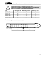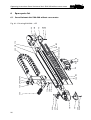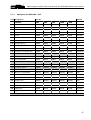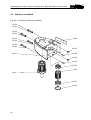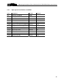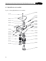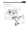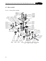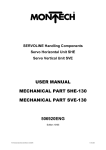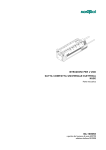
1
OPERATING INSTRUCTIONS
Handling Components
SERVOLINE®
Servo Horizontal Axis SHA-340
without Servo motor
Mechanical Part
BA-100002
ENGLISH
Edition: 02/2008
®
®
Operating Instructions Servo Horizontal Axis SHA-340 without servo motor
Change index
Editions issued so far:
Edition
Comments
Order number
05/2005
Initial edition
BA-100002
08/2005
Length-dependent articles replaces
BA-100002 A
12/2005
New Proximity switch
BA-100002 B
02/2006
Validity of the User Manual
BA-100002 C
02/2008
New type plate
BA-100002 D
2
®
Operating Instructions Servo Horizontal Axis SHA-340 without servo motor
Contents
1
1.1
1.2
1.3
1.4
1.5
1.6
Important information .......................................................................................... 5
Introduction ..................................................................................................................5
EU - conformance (to EU Directive on Machines, Appendix II A)................................5
Product description and application ............................................................................5
Dangers.........................................................................................................................5
Additional information..................................................................................................6
Validity of the Operating Instructions..........................................................................7
2
2.1
2.2
2.3
Technical data ....................................................................................................... 8
Dimension sheet SHA-340 without servo motor..........................................................9
Dimension sheet SHA-340 without servo motor, detailed view of connection.........10
Load calculations ........................................................................................................11
3
3.1
3.2
3.3
Installation........................................................................................................... 13
Mechanical Structure ..................................................................................................13
Laying cables and hoses from additional equipment ................................................14
Connecting the inductive proximity switch................................................................15
4
4.1
4.2
4.3
4.4
Maintenance........................................................................................................ 16
Lubrication ..................................................................................................................16
Setting the slide play ..................................................................................................18
Changing the inductive proximity switch...................................................................19
Mechanical zero point of the slide .............................................................................20
5
5.1
5.2
5.3
Replacing the guide elements and drive elements ............................................. 21
Changing the toothed belt of the slide......................................................................21
Setting the toothed belt pretension (slide)................................................................22
Changing shafts and rollers........................................................................................24
6
6.1
6.1.1
6.2
6.2.1
6.3
6.3.1
6.4
6.4.1
6.5
6.5.1
Spare parts list .................................................................................................... 26
Servo Horizont Axis SHA-340 without servo motor ..................................................26
Spareparts list SHA-340-...-OZ ...................................................................................27
Left drive assembled ..................................................................................................28
Spare parts list Left drive assembled .........................................................................29
Right deflection unit assembled.................................................................................30
Spare parts list Right deflection unit assembled .......................................................31
Hose holder assembled ..............................................................................................32
Spare parts list Hose holder assembled.....................................................................33
Slide assembled ..........................................................................................................34
Spare parts list Slide assembled.................................................................................35
3
®
®
Operating Instructions Servo Horizontal Axis SHA-340 without servo motor
7
7.1
General information ............................................................................................ 36
Environmental compatibility and disposal .................................................................36
8
Picture index ....................................................................................................... 37
4
®
Operating Instructions Servo Horizontal Axis SHA-340 without servo motor
1
Important information
1.1 Introduction
This operating instruction describes the mechanical design, the load limits, installation,
maintenance and spare parts of the Servo Horizontal Axis.
1.2 EU - conformance (to EU Directive on Machines, Appendix II A)
Regulations and standards taken into account:
! EU Directive on Machines 89/392/EEC, 91/368/EEC
Manufacturer:
Montech AG
Gewerbestrasse 12
CH-4552 Derendingen
Phone +41 (0) 32 681 55 00
Fax
+41 (0) 32 682 19 77
1.3 Product description and application
The servo horizontal axis SHA-340 is designed for electrical operation. The position-controlled
linear axis serves as a basic element for assembly of portal loaders. Depending on the size of the
unit, movements along the x axis up to 400, 600, 800, 1000 or 1200 mm are possible. For
example, Linear Units (LEP), Compact Universal Slides (KUS), Servo Vertical Axes (SVA) or Servo
Vertical Units (SVE) can be fitted to carry out vertical movements. Units of other systems or any
tool-bearing units can be attached as long as they do not exceed the load limits of the Servo
Horizontal Axis SHA-340.
Servo Horizontal Axes SHA-340 which have been upgraded to portal loaders are suitable for
many and varied tasks, such as loading of machines, small parts assembly, transposition,
packaging, palletizing and parts supply from magazines containing workpieces.
1.4 Dangers
The use of Servo Horizontal Axis SHA-340 in equipment is permissible only when they are
provided with protection by movable, separating protective devices according to EN 292-2
Section 4.2.2.3.
It is essential to observe the operating conditions and safety notes described in the operating
instruction.
It is absolutely essential that you keep within the stated load limits.
5
®
®
Operating Instructions Servo Horizontal Axis SHA-340 without servo motor
! During maintenance work on the Servo Horizontal Axis, ensure that the
drive power is switched off. The servo amplifier must be disconnected
from the supply voltage. Switch off the main switch or main contact.
! Switch off the enable signal
! Switch off the mains power (L1, L2, L3)
! Ensure that no unauthorized switching-on of the supply voltage can
occur.
! Failure to observe these safety measures may result in death or severe
personal injuries or material damage.
1.5 Additional information
The aim of the present User Manual is to enable users to employ Servo Horizontal Axis SHA-340
correctly and safely. Should further information be required in relation to your particular application, please
contact the manufacturer.
When reordering User Manuals, it is essential to quote the reference number, the product name
and serial number.
This document can be obtained from our homepage www.montech.com.
Fig. 1.5-1: Description type plate
Reference number
Product name
Serial number
Montech AG
Management
U. D. Wagner
6
C. Wullschleger
®
Operating Instructions Servo Horizontal Axis SHA-340 without servo motor
1.6 Validity of the Operating Instructions
Our products are continually updated to reflect the latest state of the art and practical experience. In line
with product developments, our User Manuals are continually updated.
Every User Manual has an order number (e.g. BA-100002) and an edition number (e.g. 02/2008). The order
number and the addition number are shown on the title page.
Validity table
Complete designation
Short designation
Art. No.
SHA-340-400 without Servo motor
SHA-340-400-OZ
51532
SHA-340-600 without Servo motor
SHA-340-600-OZ
56132
SHA-340-800 without Servo motor
SHA-340-800-OZ
56133
SHA-340-1000 without Servo motor
SHA-340-1000-OZ
56134
SHA-340-1200 without Servo motor
SHA-340-1200-OZ
56135
7
®
®
Operating Instructions Servo Horizontal Axis SHA-340 without servo motor
2
Technical data
SHA-340400-OZ
[mm]
400
Max. stroke
Max. permissible monting mass
SHA-340600-OZ
600
SHA-340800-OZ
800
SHA-3401000-OZ
1000
SHA-3401200-OZ
1200
[kg]
8
8
8
8
8
Max. stat. moment M0xmax
1)
[Nm]
63
63
63
63
63
Max. stat. moment M0ymax
1)
[Nm]
18
18
18
18
18
Max. stat. moment M0zmax
1)
[Nm]
36
36
36
36
36
Max. stat. force Fxmax
1)
[N]
400
400
400
400
400
Max. stat. force Fymax
1)
[N]
100
100
100
100
100
Max. stat. force Fzmax
1)
[N]
450
450
450
450
450
Max. speed
2)
[m/s]
2
2
2
2
2
Max. acceleration
3)
2
[m/s ]
Acceleration ramp
10
sin
Own weight
[kg]
Reference position approach switch
Ambient conditions: Ambient
conditions
Rel. humidity
[°C]
Air purity
Warranty period
10
2
sin
7.7
2
9.0
10
sin
2
10.4
10
sin
2
11.7
10
sin2
13.0
Integrated inductive proximity switch PNP
10 ... 50
5% ... 85% (without condensation)
normal workshop atmosphere
2 years from the date of delivery
Installation position
horizontal
Material
aluminium, steel, plastic
1) See load calculations
2) Relationship between the slide speed and the motor speed:
VSchlitten = π • dw • nMotor
Slide speed
Effective diameter of drive pinion
Motor speed
: VSchlitten ≤• 2m/s
= 35.01 mm
: dw
-1
: nMotor • ≤ 1091 min
2
3) At max. permissible installation mass and with a sin -shaped ramp
When adjusting the servo amplifier, it is essential to choose the acceleration
2
ramp of the shape sin . A trapezoidal ramp would mean premature wear of the
guide.
8
®
Operating Instructions Servo Horizontal Axis SHA-340 without servo motor
2.1 Dimension sheet SHA-340 without servo motor
Fig. 2.1-1: Dimension sheet SHA-340-...-OZ
A
75
30 22.5
15
15
30
M5 7 depth (4x)
64
75
M5 7 depth (4x)
88
98
91.5
c
a
b
d
103
20
107
46
40
52
72
65
107
PG 29
20
26
103
60
A
120
4
46
53
75.5
11
37
276
a
b
c
d
SHA-340-400-OZ
400
606
566
820
SHA-340-600-OZ
600
806
766
1020
SHA-340-800-OZ
800
1006
966
1220
SHA-340-1000-OZ
1000
1206
1166
1420
SHA-340-1200-OZ
1200
1406
1366
1620
9
®
®
Operating Instructions Servo Horizontal Axis SHA-340 without servo motor
2.2 Dimension sheet SHA-340 without servo motor, detailed view of connection
0.5x45°
Fig. 2.2-1: Dimension sheet SHA-340-...-OZ, detailed view of connection
Ø 22
29.5
37
26
Ø 12h7
Ø
50
5*
Ø 5E8**
M
±0
.1
M
5*
17.68 ±0.1
35.36 ±0.01
*
**
10
4 x M5: depth 11
3 x Ø5E8 : depth 7
Ø 5E8**
Ø 5E8**
5*
35.36 ±0.01
M
17.68±0.1
5*
max. Ø 61
M
®
Operating Instructions Servo Horizontal Axis SHA-340 without servo motor
2.3 Load calculations
The load calculations stated in the technical data are maximum values for a single load. The
following calculations apply to the combined loads experienced in practical applications:
Definition of the loads
Fig. 2.3-1: Definition of the loads
Mx
Fz
Mz
Lx
Ly
Fx
Lz
My
Fy
11
®
®
Operating Instructions Servo Horizontal Axis SHA-340 without servo motor
Load calculations
a)
Dynamic load
M x = 0.001 ⋅ m ⋅ a ⋅ L z + 0.01 ⋅ m ⋅ L y
M y = 0.01 ⋅ m ⋅ (L x − 21)
M z = 0.001 ⋅ m ⋅ a ⋅ (L x − 21)
Combined dynamic load:
B=
b)
Mx My + Mz
+
≤1
50
35
Static load
(
)
M 0 x = 0.001 ⋅ Fy ⋅ L z + Fz ⋅ L y
M 0 y = 0.001 ⋅ [Fx ⋅ L z + Fz ⋅ (L x − 21)]
[
]
M 0 z = 0.001 ⋅ Fx ⋅ L y + Fy ⋅ (L x − 21)
Combined static load:
B0 =
B, B0
Mi, M0i
m
LX, LY, LZ
FX, FY, FZ
a
12
M 0x M 0 y M 0z
+
+
≤1
63
18
36
Load factor: Must not exceed the value 1!
Existing moments [Nm]
Mounting mass [kg]
Distance of moving mass from centre of gravity, or force application
distances [mm]
Acting forces [N], maximum values see «Technical Data»
2
Acceleration of the axis [m/s ]
®
Operating Instructions Servo Horizontal Axis SHA-340 without servo motor
3
Installation
3.1 Mechanical Structure
Designing the plant
When designing the plant, the following points must be taken into account:
! The Servo Horizontal Axis SHA-340 must only be operated behind a protective device
according to EN 292-2 Section 4.2.2.3.
! Realize a low-vibration Quick-Set construction.
Installation position and assembly
Tool required
Dimension Use for
Hexagon socket wrench
4 mm
®
All Quick-Set tension elements
The Servo Horizontal Axis SHA-340 is installed horizontally so that the two dovetail guides of
the bearing housing are in a horizontal position. Fastening is performed by means of the lower
or rear dovetail guide of the bearing housing (Item 130) using at least two Quick-Set tension
elements SLL-55 (Item 11).
The additional equipment is mounted by means of the dovetail guide on the adapter plate
(Item 50/40) with the aid of a tension element SLL-55 (Item 11) or SLR-15 (Item 12). For greater
rigidity, it is advisable to combine a tension element SLL-55 (Item 11) with a tension element
SLL-20 (Item 13) (utilization of the whole dovetail guide length on the adapter plate (Item
50/40)). Tension elements SLL-55/22 and SLL-20/22 can be used for laying cables.
Alternatively, the fastening threads and the positioning holes in the adapter plate (Item 50/40)
can be used (see dimensioned drawing, Fig. 2.1-1 or Fig. 2.2-1).
Fig. 3.1-1: Installation position and assembly
11
11
11
130
50/40
11
11
12
13
13
®
®
Operating Instructions Servo Horizontal Axis SHA-340 without servo motor
3.2 Laying cables and hoses from additional equipment
Cables and hoses from additional equipment can be led into the energy conducting carrier
directly at the driver (Item 40/10) or can be led in a protected manner into the energy
conducting carrier through a protective hose (Item a) which is fastened to the hose holder by
means of separately supplied circlips (Item 290). A tension relief device can be mounted on the
driver connection (Item 40/100).
The cables and hoses can be led through the opening in the duct halves into the protective hose
(Item 300) or directly to the outside.
Fig. 3.2-1: Laying cables and hoses from additional equipment
a
290
290
40/100
40/10
300
14
®
Operating Instructions Servo Horizontal Axis SHA-340 without servo motor
3.3 Connecting the inductive proximity switch
! The servo amplifier must be disconnected from the supply voltage.
Switch off the main switch or main contact.
! Ensure that no unauthorized switching-on of the supply voltage can
occur.
! Failure to observe these safety measures may result in death or severe
personal injuries or material damage.
! The length of the cable of the supplied inductive proximity switch is 5 m. The proximity
switch cable is led through the opening in the duct halves into the protective hose
(Item 300, Fig. 3.2-1) or, in the absence of a hose, directly to the outside.
! The wiring of the proximity switch corresponds to the following diagram, in accordance with
the operating instructions for the servo amplifier. After wiring, check the function of the
proximity switch.
Fig. 3.3-1: Connecting the inductive proximity switch
brown
PNP
black
blue
+24V DC
Output
Digital GND
15
®
®
Operating Instructions Servo Horizontal Axis SHA-340 without servo motor
4
Maintenance
4.1 Lubrication
! The servo amplifier must be disconnected from the supply voltage.
Switch off the main switch or main contact.
! Ensure that no unauthorized switching-on of the supply voltage can
occur.
! Failure to observe these safety measures may result in death or severe
personal injuries or material damage.
Exclusively Klüber oil “Paraliq P460“ (Montech Art.-No. 504721) may be used as lubricant.
! Lubrication interval:
! Lubrication points:
16
800 operating hours
4 lubricating nipples (Item 50/120, Fig. 4.1-2) on the slide
(Item 50, Fig. 4.1-1)
®
Operating Instructions Servo Horizontal Axis SHA-340 without servo motor
Procedure:
! Move the slide (Item 50, Fig. 4.1-1) to the end position on the motor side.
! Remove the snapped-on covers (Item 150, Fig. 4.1-1) by pulling in the direction of the arrow.
! Move the slide in the region of the removed covers so that the four lubricating nipples
(Item 50/120, Fig. 4.1-1) are accessible. Lubrication is performed using the felt wicks
(Item 50/80, Fig. 6.5-1) which are pressed against the shafts (Item 140, Fig. 6.1-1) by springs
(Item 50/110, Fig. 6.5-1).
! Replace covers (Item 150, Fig. 4.1-1) after the lubrication process.
Fig. 4.1-1: Snapped-on covers
150
150
50
Fig. 4.1-2: Lubrication
50/120
50
50/120
50/120
50/120
17
®
®
Operating Instructions Servo Horizontal Axis SHA-340 without servo motor
4.2 Setting the slide play
! The servo amplifier must be disconnected from the supply voltage.
Switch off the main switch or main contact.
! Ensure that no unauthorized switching-on of the supply voltage can
occur.
! Failure to observe these safety measures may result in death or severe
personal injuries or material damage.
Tool required
Dimension
Use for
Hexagon socket wrench
3 mm
Item 50/50
Fork wrench
12 mm
Item 50/70
! Move the slide (Item 50, Fig. 4.1-1) to the end position on the motor side.
! Remove the snapped-on covers (Item 150, Fig. 4.1-1) by pulling in the direction of the arrow.
! Move the slide in the region of the removed covers so that the hexagon nuts (Item 50/70,
Fig. 4.2-1) are accessible.
! Slightly slacken the upper nuts (Item 50/70, Fig. 4.2-1).
! Set the rollers so that there is no play by turning the eccentric pins (Item 50/50, Fig. 4.2-1)
clockwise (without pretension).
! Tighten the upper nuts (Item 50/70, Fig. 4.2-1) while holding the eccentric pins (Item 50/50,
Fig. 4.2-1) with the hexagon socket wrench so that the tension nut position does not change.
! Replace covers (Item 150, Fig. 4.1-1) according to the setting procedure.
Fig. 4.2-1: Setting the slide play
50/70
50/50
50/50
50/70
18
®
Operating Instructions Servo Horizontal Axis SHA-340 without servo motor
4.3 Changing the inductive proximity switch
! The servo amplifier must be disconnected from the supply voltage.
Switch off the main switch or main contact.
! Ensure that no unauthorized switching-on of the supply voltage can
occur.
! Failure to observe these safety measures may result in death or severe
personal injuries or material damage.
Tool required
Dimension
Use for
Hexagon socket wrench
4 mm
Item 40/170
Hexagon socket wrench
2 mm
Item 110
! Undo the machine screws (Item 40/170) and remove the duct halves (Item 40/30).
! Undo the clamping screw (Item 110) and remove the proximity switch (Item 210).
! Push the new proximity switch (Item 210) to the stop in the hole in the bearing housing and
fasten by slightly tightening the clamping screw (Item 110).
! Check for clearance by moving the slide body.
! Connect the inductive proximity switch (Item 210) according to the section "Connecting the
inductive proximity switch".
! The LED on the proximity switch (Item 210) must light up with applied supply voltage if the
carriage is in the end position on the motor side. If this condition is fulfilled, the reference
traverse can be performed after the duct halves (Item 40/30) have been mounted.
Fig. 4.3-1: Changing the inductive proximity switch
40/170
40/170
40/30
210
110
19
®
®
Operating Instructions Servo Horizontal Axis SHA-340 without servo motor
4.4 Mechanical zero point of the slide
Position of slide when reference traverse is complete.
Fig. 4.4-1: Mechanical zero point of the slide
23
20
10
®
Operating Instructions Servo Horizontal Axis SHA-340 without servo motor
5
Replacing the guide elements and drive elements
5.1 Changing the toothed belt of the slide
! Carry out a reference traverse.
! Switch off the supply voltage.
! The servo amplifier must be disconnected from the supply voltage.
Switch off the main switch or main contact.
! Ensure that no unauthorized switching-on of the supply voltage can
occur.
! Failure to observe these safety measures may result in death or severe
personal injuries or material damage.
!
!
!
!
!
!
!
!
!
!
!
!
!
!
!
!
!
!
!
Mark the position of the slide.
Remove devices attached to the slide.
Remove the snapped-on covers (Item 150, Fig. 4.1-1) by pulling in the direction of the arrow.
Move the slide into the region of the removed covers.
Undo screw (Item 20/170, Fig. 6.3-1) and remove cover (Item 20/60, Fig. 6.3-1).
Undo hexagon nut (Item 20/150, Fig. 6.3-1) and completely relax the toothed belt by turning
the camshaft (Item 20/30, Fig. 6.3-1).
Undo machine screws (Item 50/170, Fig. 6.5-1) and unscrew by approx. 5 mm.
Remove adapter plate (Item 50/40, Fig. 6.5-1) from the slide body (Item 50/10, Fig. 6.5-1) so that
the toothed belt can be removed from the clamps (Item 50/30, Fig. 6.5-1).
Fasten new toothed belt to the end of the old one. The adhesive tape must hold reliably,
since otherwise extensive dismantling of the servo horizontal axis is required.
Carefully draw the new toothed belt through the bearing housing (Item 130, Fig. 6.1-1) and
remove the old toothed belt.
Position the ends of the new toothed belt in the clamps (Item 50/30, Fig. 6.5-1) and fix with
the adapter plate (Item 50/40, Fig. 6.5-1) by tightening the machine screws (Item 50/170,
Fig. 6.5-1) (ensure vertical positioning of the toothed belt).
Move the slide to the marked position without rotation of the motor shaft.
Slightly tension the toothed belt by turning the eccentric shaft (Item 20/30, Fig. 6.3-1) and
secure by tightening the hexagon nut (Item 20/150, Fig. 6.3-1).
Snap covers (Item 150, Fig. 4.1-1) onto the bearing housing.
Set toothed belt pretension according to "Setting the toothed belt pretension (slide)".
Mount the cover (Item 20/60, Fig. 6.3-1).
Check the work performed.
Mount attached devices to the slide.
Perform offset correction according to operator software manual "Commissioning after
maintenance work".
21
®
®
Operating Instructions Servo Horizontal Axis SHA-340 without servo motor
5.2 Setting the toothed belt pretension (slide)
! Carry out a reference traverse.
! Switch off the supply voltage.
! The servo amplifier must be disconnected from the supply voltage.
Switch off the main switch or main contact.
! Ensure that no unauthorized switching-on of the supply voltage can
occur.
! Failure to observe these safety measures may result in death or severe
personal injuries or material damage.
! Undo the machine screw (Item 20/170, Fig. 6.3-1) and remove cover (Item 20/60, Fig. 6.3-1).
! Undo hexagon nut (Item 20/150, Fig. 6.3-1).
! Set the toothed belt pretension according to the following table by turning the camshaft
(Item 20/30, Fig. 6.3-1).
! Tighten the hexagon nut (Item 20/150, Fig. 6.3-1) while holding the camshaft (Item 20/30,
Fig. 6.3-1) so that it cannot turn!
! Check the toothed belt pretension according to the following table.
! Replace cover (Item 20/60, Fig. 6.3-1).
! Perform offset correction according to the operator software manual "Commissioning after
maintenance work".
22
®
Operating Instructions Servo Horizontal Axis SHA-340 without servo motor
The initial tensions shown in the table are maximum values.
Subjecting the toothed belt to higher initial tension will result in premature
wear of the toothed belt and an increase in the noise level.
Type
Initial tension [N
Deflection force F [N]
Excursion x [mm]
SHA-340-400
200
19
9
SHA-340-600
200
11
9
SHA-340-800
200
8
9
SHA-340-1000
200
6
9
SHA-340-1200
200
4.8
9
x
Fig. 5.2-1: Setting the toothed belt pretension (slide)
F
=
=
23
®
®
Operating Instructions Servo Horizontal Axis SHA-340 without servo motor
5.3 Changing shafts and rollers
Always change the shafts (Item 140, Fig. 6.1-1) together with the associated rollers
(Item 50/90, Fig. 6.5-1)!
1. Removing the slide
! Carry out a reference traverse.
! Switch off the supply voltage.
! The servo amplifier must be disconnected from the supply voltage.
Switch off the main switch or main contact.
! Ensure that no unauthorized switching-on of the supply voltage can
occur.
! Failure to observe these safety measures may result in death or severe
personal injuries or material damage.
!
!
!
!
!
!
!
!
!
Mark slide position.
Remove attached devices from the slide.
Undo machine screw (Item 20/170, Fig. 6.3-1) and remove cover (Item 20/60, Fig. 6.3-1).
Undo machine screw (Item 230, Fig. 6.1-1) and remove cover (Item 70, Fig. 6.1-1) (mounted
only on deflection side or right deflection unit (Item 20, Fig. 6.1-1)).
Relax toothed belt (Item 170, Fig. 6.1-1) by undoing the hexagon nut (Item 20/150,
Fig. 6.3-1) and turning the camshaft (Item 20/30, Fig. 6.3-1).
Move the slide by hand to the end position on the deflection side.
Undo machine screws (Item 50/170, Fig. 6.5-1) and remove together with the adapter plate
(Item 50/40, Fig. 6.5-1), thereby releasing the toothed belt (Item 170, Fig. 6.1-1).
Undo machine screws (Item 20/180, Fig. 6.3-1) and remove deflection shaft assembly
(Item 20, Fig. 6.1-1), if possible without unhooking the toothed belt.
Push slide out of the bearing housing (Item 130, Fig. 6.1-1) (pay attention to the position of
the felt wicks (Item 50/80, Fig. 6.5-1)).
2. Changing the rollers (Fig. 6.5-1)
! Unscrew camshaft (Item 50/50) or concentric shaft (Item 50/60) from the nut (Item 50/70). For
this purpose, hold the hexagon socket of the camshaft or concentric shaft with a hexagon
socket wrench size 3 mm.
! Change the rollers (Item 50/90) (always change all rollers).
! Mount concentric shaft (Item 50/60), shim ring (Item 50/100), roller (Item 50/90) and nut
(Item 50/70) and tighten. Apply opposing force by holding with hexagon socket wrench.
! Mount camshaft (Item 50/50), shim ring (Item 50/100), roller (Item 50/90) and nut (Item 50/70)
(cam in lower position). Tighten the nut only lightly. This will be tightened only when the slide
play has been set.
24
®
Operating Instructions Servo Horizontal Axis SHA-340 without servo motor
3. Changing the shafts (Fig. 6.1-1)
The shafts (Item 140) can be withdrawn from the grooves in the bearing housing on the side of
the deflection roller. If the shafts cannot be pulled out when the servo horizontal axis is
mounted, remove the axis from the installation.
! Pull out shafts (Item 140).
! Clean grooves in bearing housing (Item 130).
! Push in new shafts as far as they will go.
4. Final assembly
! Push slide (Item 50, Fig. 6.1-1) into the bearing housing (Item 130, Fig. 6.1-1) paying attention
to the position. Important: Pay attention to felt wicks and position of the rollers!
! Eliminate slide play according to "Setting the slide play" (covers (150) not yet mounted).
! Insert the toothed belt (Item 170, Fig. 6.1-1) in deflection assembly (Item 20, Fig. 6.1-1) and
screw deflection assembly to the bearing housing (Item 130, Fig. 6.1-1).
! Position the ends of the toothed belt in the clamps (Item 50/30, Fig. 6.5-1) and fix with the
adapter plate (Item 50/40, Fig. 6.5-1) by tightening the machine screws (Item 50/170,
Fig. 6.5-1) (ensure vertical positioning of the toothed belt).
! Push the carriage to the marked position without rotating the motor shaft.
! Snap covers (Item 150, Fig. 6.1-1) onto the bearing housing.
! Set toothed belt pretension according to "Setting the toothed belt pretension (slide)".
! Mount cover (Item 70, Fig. 6.1-1).
! Mount cover (Item 20/60, Fig. 6.3-1).
! Check the work performed.
! Mount attached devices to the slide.
! Perform offset correction according to operator software manual "Commissioning after
maintenance work".
25
®
®
Operating Instructions Servo Horizontal Axis SHA-340 without servo motor
6
Spare parts list
6.1 Servo Horizont Axis SHA-340 without servo motor
26
900 50
910
250
230
70
10
220
240
80
300
110
100
210
120 290 290 40
150 150
90
160 160
150 150 140 140
250
230
70
310
200 130 170
20
Fig. 6.1-1: Drawing SHA-340-...-OZ
®
Operating Instructions Servo Horizontal Axis SHA-340 without servo motor
6.1.1
Spareparts list SHA-340-...-OZ
Item Designation
Art. No.
Material
SHA-340-
-400
-600
-800
-1000
-1200
10
Left drive assembled
56363
56363
56363
56363
56363
Various
20
Right deflection unit assembled 56362
56362
56362
56362
56362
Various
40
Hose holder assembled
56364
56364
56364
56364
56364
Various
50
Slide assembled
50379
50379
50379
50379
50379
Various
70
Cover
50588
50588
50588
50588
50588
ABS lack.
80
Cover small
51356
51356
51356
51356
51356
ABS lack.
90
Damping plate
50382
50382
50382
50382
50382
Steel
100
Clamping piece
47906
47906
47906
47906
47906
Steel
110
Clamping screw
47904
47904
47904
47904
47904
Steel
120
Lubrication plate
50541
50541
50541
50541
50541
PVC
130
Bearing housing SHA-340
50505
50523
50524
50525
50526
Aluminium
140* Shaft Ø6h6
50948
50527
50528
50529
50535
Steel
150
Cover SHA-340
50515
50515
50515
50515
50515
Aluminium
160
Cover SHA-340
50515
50516
50517
50518
50519
Aluminium
170* Toothed belt
50595
50596
50597
50598
50599
PUR
200
508125
508125
508125
508125
508125
PA
210* Proximity switch
508842
508842
508842
508842
508842
Various
220
Machine screw M4x16
505328
505328
505328
505328
505328
Steel
230
Machine screw M5x20
504799
504799
504799
504799
504799
Steel
240
Ribbed washer M4
502606
502606
502606
502606
502606
Steel
250
Ribbed washer M5
505254
505254
505254
505254
505254
Steel
290
Circlip ø35 f.s.
502461
502461
502461
502461
502461
Steel
300
Protective hose PG29
503693
503693
503693
503693
503693
PA
310
Load warning plate
56180
56180
56180
56180
56180
Polyester
900
Type plate
41620
41620
41620
41620
41620
Polyester
910
Type plate plaque
48508
48508
48508
48508
48508
PUR
Energy conducting carrier link
* Are wear parts and on stock.
27
®
®
Operating Instructions Servo Horizontal Axis SHA-340 without servo motor
6.2 Left drive assembled
Fig. 6.2–1: Drawing Left drive assembled
10/150
10/160
10/150
10/160
10/150
10/160
10/40
10/150
10/160
10/130
10/10
10/140
10/130
10/140
10/100
10/30
10/20
10/110
10/120
28
®
Operating Instructions Servo Horizontal Axis SHA-340 without servo motor
6.2.1
Spare parts list Left drive assembled
Item
Designation
Art. No.
10
Left drive assembled
56363
10/10
Housing for left drive
50493
Aluminium
10/20
Gear shaft assembled
50522
Steel
10/30
Deflection axle assembled
50521
Steel /Aluminium
10/40
Montech logo
50536
PVC
10/100
Deep-groove ball bearing 6000-2RS 501378
Steel
10/110
Deep-groove ball bearing 6001-2Z
505244
Steel
10/120
Circlip ø28 f.B
502474
Steel
10/130
Plug-in stop round
506160
NR
10/140
Straight pin Ø4x18h6
502039
Steel
10/150
Machine screw M5x16
501640
Steel
10/160
Ribbed washer M5
502365
Steel
Material
29
®
®
Operating Instructions Servo Horizontal Axis SHA-340 without servo motor
6.3 Right deflection unit assembled
Fig. 6.3–1: Drawing Right deflection unit assembled
20/190
20/170
20/180
20/200
20/60
20/150
20/180
20/200
20/210
20/70
20/180
20/200
20/180
20/200
20/160
20/10
20/140
20/160
20/40
20/140
20/100
20/110
20/50
20/20
20/120
20/100
20/130
20/30
30
®
Operating Instructions Servo Horizontal Axis SHA-340 without servo motor
6.3.1
Spare parts list Right deflection unit assembled
Item
Designation
Art. No.
20
Right deflection unit assembled
56362
20/10
Housing deflection unit right
50492
Aluminium
20/20
Toothed disc 5MR-30S
50458
Aluminium
20/30
Eccentric shaft
50455
Steel
20/40
Distance ring
50353
Steel
20/50
Deflection axle assembled
50521
Steel /Aluminium
20/60
Cover
50588
ABS lack.
20/70
Montech logo
50536
PVC
20/100
Deep-groove ball bearing 6904-RS
508130
Steel
20/110
Deep-groove ball bearing 6000-2RS 501378
Steel
20/120
Deep-groove ball bearing 6001-2Z
505244
Steel
20/130
Circlip ø28 f.B
502474
Steel
20/140
Plug-in stop round
506160
NR
20/150
Hex nut M10x1
508132
Steel
20/160
Straight pin Ø4h6x18
502039
Steel
20/170
Machine screw M5x20
504799
Steel
20/180
Machine screw M5x16
501640
Steel
20/190
Ribbed washer M5
505254
Steel
20/200
Ribbed washer M5
502365
Steel
20/210
Washer 10.5/25x2
502589
Steel
Material
31
®
®
Operating Instructions Servo Horizontal Axis SHA-340 without servo motor
6.4 Hose holder assembled
Fig. 6.4–1: Drawing Hose holder assembled
40/150
40/20
40/140
40/150
40/140
40/100
40/10
40/180
40/180
40/130
40/130
40/120 40/120
40/50
40/170
40/150
40/150
40/160
40/190
40/110
40/160
40/190
40/110
40/170
40/30
40/150
40/150
40/40
32
®
Operating Instructions Servo Horizontal Axis SHA-340 without servo motor
6.4.1
Spare parts list Hose holder assembled
Item
Designation
Art. No.
40
Hose holder assembled
56364
40/10
Driver
50449
Steel
40/20
Hose holder
50452
Aluminium
40/30
Duct half
50498
ABS
40/40
Duct half left
50508
ABS
40/50
Fixed connection
50506
PA
40/100
Driver connection
508124
PA
40/110
Setting nut M4
502615
Steel
40/120
Setting nut M5
502614
Steel
40/130
Straight pin Ø5h6x10
502047
Steel
40/140
Straight pin Ø4h6x8
502032
Steel
40/150
Machine screw M5x8
506668
Steel
40/160
Machine screw M4x8
501618
Steel
40/170
Machine screw M5x30
501768
Steel
40/180
Countersunk screw M6x12
501823
Steel
40/190
Ribbed washer M4
502364
Steel
Material
33
®
®
Operating Instructions Servo Horizontal Axis SHA-340 without servo motor
6.5 Slide assembled
Fig. 6.5–1: Drawing Slide assembled
50/170
50/170
50/180
50/180
50/170
50/170
50/180
50/180
50/40
50/140
50/120 50/130 50/30
50/110
50/80 50/130
50/150
50/150
50/140
50/120
50/160
50/180
50/160
50/180
50/20
50/110
50/30
50/90
50/100
50/130
50/130
50/90
50/70 50/70
50/100
50/70
50/80 50/70
50/120
50/120
50/80
50/110
50/20
50/100
50/90
34
50/50
50/60
50/10
50/90
50/100
50/160
50/180
50/50 50/110
50/60
50/180
50/160
50/80
®
Operating Instructions Servo Horizontal Axis SHA-340 without servo motor
6.5.1
Spare parts list Slide assembled
Item
Designation
Art. No.
50
Slide assembled
50379
50/10
Slide body
50356
Aluminium
50/20
End plate
50363
Aluminium
50/30
Clamp
50357
Aluminium
50/40*
Adapter plate
50361
Aluminium
50/50*
Eccentric pin assembled
50374
Steel
50/60*
Concentric pin assembled
50375
Steel
50/70*
Nut
50358
Steel
50/80*
Felt wick
40921
Wool felt
50/90*
Roller
503663
Steel
50/100* Shim ring Ø8/14x1
505919
Steel
50/110* Pressure spring
504119
Steel
50/120* Lubrication nipple
504554
Brass
50/130
Straight pin Ø4x12h6
502035
Steel
50/140
Straight pin Ø5x24h6
506164
Steel
50/150
Straight pin Ø4x 8h6
502032
Steel
50/160
Machine screw M4x12
501620
Steel
50/170
Machine screw M4x20
501624
Steel
50/180
Ribbed washer M4
502364
Steel
Material
* Are wear parts and on stock.
35
®
®
Operating Instructions Servo Horizontal Axis SHA-340 without servo motor
7
General information
7.1 Environmental compatibility and disposal
Material used
!
!
!
!
!
!
!
!
!
!
Aluminium
Steel
Brass
Wool fibres
Polyester
ABS (Acrylonitrile-butadiene-styrene)
PUR (Polyurethane)
PA (Polyamide)
PVC (Polyvinyl chloride)
NR (Natural rubber)
Surface treatment
! Anodic oxidation of aluminium
! Blackening of steel
! Coating of aluminium and plastic
Shaping processes
!
!
!
!
Profile extrusion of aluminium
Casting of aluminium
Material-removing processes (metals and plastics)
Injection moulding of plastics
Emissions during operation
! None
Disposal
Servo Horizontal Axes (SHA-340) or handling units upgraded to portal loaders that are no longer
in use are to be dismantled and recycled according to the type of material. The type of material
for each part is stated in the spare parts list. Any non-recyclable material is to be disposed of
properly according to materials, taking into account the regulations which apply in your location.
36
®
Operating Instructions Servo Horizontal Axis SHA-340 without servo motor
8
Picture index
Fig. 1.5-1: Description type plate..................................................................................................... 6
Fig. 2.1-1: Dimension sheet SHA-340-...-OZ .................................................................................... 9
Fig. 2.2-1: Dimension sheet SHA-340-...-OZ, detailed view of connection ................................... 10
Fig. 2.3-1: Definition of the loads................................................................................................... 11
Fig. 3.1-1: Installation position and assembly ................................................................................ 13
Fig. 3.2-1: Laying cables and hoses from additional equipment ................................................... 14
Fig. 3.3-1: Connecting the inductive proximity switch................................................................... 15
Fig. 4.1-1: Snapped-on covers........................................................................................................ 17
Fig. 4.1-2: Lubrication ..................................................................................................................... 17
Fig. 4.2-1: Setting the slide play..................................................................................................... 18
Fig. 4.3-1: Changing the inductive proximity switch...................................................................... 19
Fig. 4.4-1: Mechanical zero point of the slide ................................................................................ 20
Fig. 5.2-1: Setting the toothed belt pretension (slide)................................................................... 23
Fig. 6.1-1: Drawing SHA-340-...-OZ................................................................................................ 26
Fig. 6.2–1: Drawing Left drive assembled...................................................................................... 28
Fig. 6.3–1: Drawing Right deflection unit assembled .................................................................... 30
Fig. 6.4–1: Drawing Hose holder assembled.................................................................................. 32
Fig. 6.5–1: Drawing Slide assembled ............................................................................................. 34
37
MONTECH AG
Gewerbestrasse 12, CH-4552 Derendingen
Fon +41 32 681 55 00, Fax +41 32 682 19 77
[email protected], www.montech.com