1
October 2001
224-715-00 B
Site-Programmable Volt &
Milliamp Limit Alarm Trips
SPA
SPA
Site-Programmable Volt &
Milliamp Limit Alarm Trips
HLPRG
The Interface Solution Experts
1
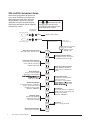
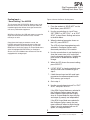
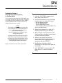
SPA HLPRG Quickstart Guide
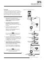
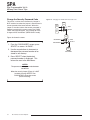
Use the front push-buttons to quickly and
easily setup the SPA for your application.
After programming your alarm using the
diagram below, install the unit into your
application using the connection diagram
and terminal designation table on pages 35
and 36 of this manual.
Use
or
push buttons to scroll
through menus and sub-menus.
Use SELECT push button to access
menu and/or make a choice.
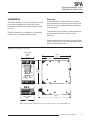
Front Panel
Push Buttons
Inactive during operation.
VIEW
VIEW current settings
SELECT
Inactive during operation.
Security Jumper
installed in OFF position.
Security Jumper
installed in ON position.
ENTER
PASS
Select Volt or Current Input:
Select input type. Defaults to mA.
SEL
V/I
CONF
OPTS
Scale Input "Smart Scaling":
Set the values to be displayed
at zero and full scale without
calibration equipment.
2
The Interface Solution Experts
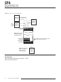
Trim Output:
Connect the SPA into a calibration
setup as shown in the manual and
trim the analog output.
(Requires –AO Option)
CONF
ALRM
PASS
WORD
Exit Configuration Menu:
Return to process display.
Enter Custom Curve:
Program up to 20 linearization
points into memory.
(This menu is only available if
SCLE
AO
TRIM
OUT
Configure Alarm:
Set trip point, deadband,
high\low trip, delay, and
latching\non-latching.
Apply Input "Bench Scaling":
Using calibration equipment,
capture the zero and full scale
values.
SCLE
DSPL
ENTR
CURV
Scale Analog Output:
Connect the SPA into a calibration
setup as shown in the manual
and trim the analog output.
(Requires –AO Option)
Configure Function Options:
Set engineering units, and custom
or standard linearization mode.
SCLE
INPT
APLY
INPT
Scale the Display:
Custom-scale the display.
(This menu is only available if
Enter the password
code to enable
settings changes.
(Default = 55)
CONF
EXIT
Password:
View or change password.
Table of Contents
SPA Volt/Milliamp Alarm Trips .......................................................................... 4
Programmable Inputs .......................................................................................................... 4
Programmable Outputs ....................................................................................................... 4
Programmable Display ....................................................................................................... 4
Programmable Input Failure Alarms ................................................................................... 4
Universal Mounting ............................................................................................................. 4
Specifications ................................................................................................... 5
Alarm Terminology ........................................................................................... 6
Internal Settings................................................................................................ 7
Programming the HLPRG SPA........................................................................ 9
Main Menu/View Settings ................................................................................................... 9
Password .......................................................................................................................... 11
Select Input Type .............................................................................................................. 12
Configure Function Options .............................................................................................. 13
Scaling Input – "Smart Scaling" the HLPRG ..................................................................... 15
Applying Input – "Bench Ranging" the HLPRG ................................................................ 17
Scaling the Display – Setting the Engineering Units in Custom Mode .............................. 19
Programming SPA Linearization – Entering Segment Endpoints in Custom Mode .......... 21
Scaling the Analog Output – SPAs with AO ......................................................................25
Trim Output ....................................................................................................................... 25
Configure Alarm(s) ............................................................................................................ 28
Change the Security Password Code ............................................................................... 32
Installation ....................................................................................................... 33
Mounting ........................................................................................................................... 33
Connections ...................................................................................................................... 34
Operation .........................................................................................................36
LEDs ................................................................................................................................. 36
Manual Reset ....................................................................................................................36
Error Codes ....................................................................................................................... 37
Customer Service ........................................................................................... 37
The Interface Solution Experts
3
SPA
Site-Programmable Volt &
Milliamp Limit Alarm Trips
SPA Volt/Milliamp Alarm Trips
Programmable Input Failure Alarms
This is the users’ manual for the Volt/Milliamp Input
model of the Moore Industries’ Site-Programmable
process Alarms (SPA). The SPA monitors a process
variable and provides up to four, fully configurable,
contact closure outputs whenever that input falls
outside a user-set, high or low trip point. SPAs are
typically used to activate a warning light, bell, or
buzzer; or to initiate a system shutdown, thus acting
as simple, but highly reliable and effective means of
safe-guarding a process.
The SPA can be ordered with 1, 2, 3, or 4 contact
closure alarms. Each alarm can be individually
programmed for a different trip point, deadband, delay,
high or low alarming, latching or non-latching, and
failsafe or non-failsafe operation.
The SPA also provides two ways to set the alarm trip
point. If an input source is either unavailable or
inconvenient, the unit’s front panel push buttons and
integral liquid crystal display (LCD) can be used to
enter the desired trip point.
Programmable Inputs
The Programmable Current/Voltage unit, or HLPRG
SPA (for “High Level” Programmable input), handles
either current or voltage inputs in any user-set span in
a 0-50mA or 0-10V range. The HLPRG comes
standard with transmitter excitation capability for use
with 2-wire loop transmitters.
Programmable Outputs
The SPA HLPRG can be equipped with a fully
scaleable analog output (-AO) option with the capacity
of being switched by the user to either 0-20mA (source
or sink), or 0-5V.
The source/sink setting for the optional analog output
is controlled by DIP switches that are located behind
an easy-to-remove access panel inside the unit’s
housing.
Programmable Display
With the Volt/Milliamp Input SPA, the user can choose
between the Linear function mode and the Custom
function mode.
In the Linear Mode, the SPA HLPRG behaves much
like a simple input meter. The display is set by the
user to show the input in either mA or volts. Its
scaling is tied to any input scaling performed. (If
equipped with the –AO option, the SPA’s output can be
scaled independent of the input.)
The SPA HLPRG’s Custom Mode sets the unit up for
independent programming of input scaling, display
scaling, and, if equipped with the –AO option, output
scaling. In Custom Mode, the user selects °C, °F, %
of scale, Blank (for raw display), or a pre-specified
4-place custom engineering unit label.
4
The Interface Solution Experts
When a source is available, the SPA can capture trip
points by setting the input to the desired trip and
pressing the appropriate button.
Failsafe or Non-failsafe alarm functioning is controlled
by DIP switches that are located behind an easy-toremove access panel inside the unit’s housing.
Universal Mounting
The SPA is housed in a “universal” DIN case that can
be mounted on both 32mm G-type (EN50035) and
35mm Top-Hat (EN50022) DIN-rail. The Installation
section of this manual gives the dimensions of the
housings for the various SPA configurations.
SPA
Site-Programmable Volt &
Milliamp Limit Alarm Trips
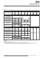
Specifications
Performance Repeatability: Trip point
repeats within ±0.05% of
input span
Display Accuracy: ±1
digit; When scaling the
display (in Custom Mode),
high input-to-display span
ratios decrease display
accuracy
Input Accuracy:
Current input, ±5µA;
Voltage inputs, ±1mV
Stability: ±0.1% of
calibrated span,
maximum, over 6 months
Deadband: 11.5V or
57.5mA, maximum in
Linear Mode; equivalent of
maximum input range in
user-set engineering units
in Custom Mode
Response Time: 600
milliseconds (Defined as
time from step change on
input to alarm state
change when alarm
is set to trip at mid-point)
Alarm Trip Delay:
Programmable from 0-60
seconds
Line Voltage Effect:
±0.005% of span for a
1% change in line voltage
(ac or dc)
Isolation: 1000Vrms
between case, input,
output (units with -AO
option) and power
terminals (NOTE: High
voltage effect of
±0.0004% of output
span/V possible with
prolonged exposure to ac
voltage above 200Vac)
Power Consumption:
2-4W, nominal;
6W, maximum
Performance Input Impedance: 1MΩ
(continued) for voltage inputs; 20Ω
nominal for current inputs
Input Over-Range
Protection: 18Vdc for
voltage inputs; 180% of
maximum input span
Performance
with Analog
Output (-AO
Option)
WITH ANALOG OUTPUT
Output Accuracy:
±0.03% of output span
(includes the combined
effects of linearity,
hysteresis, repeatability,
and adjustment
resolution)
Response Time: 250
msec maximum time for
output to go from 10% to
90% for step change on
input
Ripple (up to 120Hz):
Current output, 10mV
peak-to-peak max. when
measured across a 250Ω
resistor; Voltage output,
15mV peak-to-peak max.
Output Limiting: 117%
of span max., 115% of
span typical
Load Effect: ±0.01% of
span from 0 to maximum
load resistance on current
output
Ambient Operating Range:
Conditions –25°C to +65°C
(–13°F to +149°F)
Storage Range:
–40°C to +80°C
(–40°F to +176°F)
Ambient Temperature
Effect: ±0.005% of outut
span per °C maximum;
±15ppm of input signal
Ambient Relative Humidity:
Conditions 0–95% non-condensing
(continued) RFI/EMI Protection:
30V/m - ABC ≤0.5% error
in reading when tested
according to SAMA
standard PMC 33.1
Common Mode
Rejection:
100dB @ 60Hz
Normal Mode Rejection:
40dB @ 60Hz (measured
w/current input)
Adjustments Front panel push buttons
control settings for zero,
span, alarm trip points,
high/low alarms, etc.;
Easy access internal
settings select current
(source or sink) or voltage
output, and failsafe or
non-failsafe alarm
functions; Internal jumper
and menu password
protect parameter settings
Indicators LCD: 2x4 character,
backlit, alphanumeric
readout accurate to the
nearest digit.
Range: -9999 to 9999;
Decimal point can be
user-set when in Custom
Mode
LED’s: Dual-color TRIP
light (one for each relay)
shows green for nonalarm, red for alarm;
READY light indicates
normal operation,
extinguishes in the event
of any internal failure;
INPUT light is always
green
Weight 456 to 513 g
(16.1 to 18.1 oz)
Specifications and information subject to change without notice.
The Interface Solution Experts
5
SPA
Site-Programmable Volt &
Milliamp Limit Alarm Trips
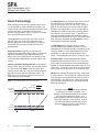
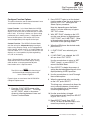
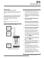
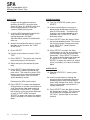
Alarm Terminology
Before setting up the SPA, or incorporating the unit
in your application, Moore Industries suggests that
all users take a few moments to become familiar with
some of the terms associated with the use of
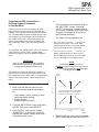
process instrumentation alarms. Figure 1 illustrates
the way the SPA alarms operate.
The Trip Point is the process input level at which
the user wants an alarm relay to change state,
typically going into an alarm condition, or “tripping”.
In the SPA, the user sets the trip point for each
installed relay.
High\Low Alarms: High Alarms trip when the
process input goes above the trip point. Low Alarms
trip when the process input drops below the trip
point. Each of the SPA outputs can be set by the
user to function independently as either high or low
alarms.
Latching and Non-latching Alarms; once tripped, a
latching alarm remains in alarm until the input returns
to a non-alarm level AND is manually reset. Nonlatching alarms return to a non-alarm state whenever
the process input returns to the Reset Point. The
SPA relays can be set by the user to function as
either latching or non-latching.
Figure 1. How Alarms Work with the Process Input
The Reset Point is the process input level at which
the user wants an alarm relay to change state,
typically going from alarm to non-alarm. The reset
point is not necessarily the same as the trip point,
because most applications call for a buffer zone or
“Deadband” around the trip point to allow for minute
fluctuations in the process input. In the SPA, the
reset point is determined by the deadband setting.
Latching SPA alarms will not “clear” unless the reset
point has been reached or passed AND the manual
reset contacts have been shorted.
The Deadband is the range in which an alarm
remains tripped even after the process input has
returned to or passed the trip point. Deadband is not
required. When it is not incorporated into an alarm
application, the trip point and reset point are the
same. The deadband of the SPA is set by the user.
Failsafe Alarms are de-energized when tripped,
energized when the process input is at a non-alarm
level. Non-failsafe Alarms are energized whenever
tripped, de-energized when the process input is at an
alarm level. The relays in the SPA can be switched
from failsafe to non-failsafe at any time by the user.
Normal is the term used to describe the “shelf-state”
of relay contacts. The contacts of a Normally Open
relay are open (infinite resistance) when the relay is
not energized. The contacts of a Normally Closed
relay are open when the relay is energized (closed
when not energized).
IN ALARM
IN NON-ALARM
HIGH ALARM
TRIP POINT
DEADBAND
RESET
RESET
DEADBAND
LOW ALARM
TRIP POINT
TIME
6
The Interface Solution Experts
NOTE:
Sometimes a non-alarm input level is referred
to as being in a “normal” condition. This
practice is intentionally avoided in this manual.
Do not confuse the term “normal”, as in
Normally Open or Normally Closed, with a nonalarm input condition. In this manual, “normal”
is an exclusive reference to the shelf state or
quiescent state of an alarm’s relay contacts,
whether open or closed.
SPA
Site-Programmable Volt &
Milliamp Limit Alarm Trips
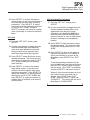
Internal Settings
The Failsafe/Non-failsafe relay and the password
security functions of the SPA are controlled by
means of simple DIP switches and a single jumper
inside the unit housing.
If the unit is equipped with the AO option, voltage
and current sink/source selection is also inside.
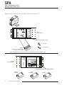
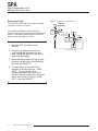
The SPA housing is fitted with a sliding access door
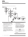
in its bottom panel. Figures 3, 4, and 5 show the
panel and the location of each of the controls for
setting:
• Password Security ON/OFF (Figure 2)
• Failsafe/Non-failsafe Alarm Function (Figure 3)
• Current Source/Sink or Voltage (Figure 4)
(Available in AO-equipped SPAs only)
NOTE:
SPAs equipped with the DPDT option make
use of switches 1 and 2 only (see Figure 3).
Figure 2. Setting the Internal Jumper for Password Security ON or OFF
SLIDING PANEL
SET PASSWORD SECURITY
PASSWORD SECURITY
IS ON. PASSWORD
REQUIRED.
AC OR DC
RELAY 1 RELAY 2 POWER
SPA UNDERSIDE
BACK
PASSWORD SECURITY
IS OFF. PASSWORD
NOT REQUIRED.
GND
NO1
CM1
NC1
NO2
CM2
NC2
NOTE: THE THREE PINS TOWARD THE LEFT SIDE OF THE COMPARTMENT
ARE FOR FACTORY TESTING ONLY.
DO NOT INSTALL JUMPERS ON THESE PINS!
The Interface Solution Experts
7
SPA
Site-Programmable Volt &
Milliamp Limit Alarm Trips
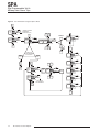
Figure 3. Setting the Internal DIP Switches for Failsafe or Non-Failsafe Alarm Function
AC OR DC
RELAY 1 RELAY 2 POWER
BACK
NO1
CM1
NC1
NO2
CM2
NC2
FRONT
SPA UNDERSIDE
GND
SET FAILSAFE/NON-FAILSAFE
1
2
3
4
=
FAILSAFE
=
NON-FAILSAFE
EXAMPLE:
ALARMS 1 & 2 = NON-FAILSAFE
ALARMS 3 & 4 = FAILSAFE
NOTE: THIS 4-POSITION SIP SWITCH MAY VARY IN LOCATION BASED ON THE TYPE OF SPA USED
BACK
(terminal
labeling)
GND
FRONT
SPA UNDERSIDE
POWER
AC OR DC
Figure 4. Setting the Internal DIP Switches for Current Source/Sink or Voltage (AO-equipped SPAs only)
SET CURRENT-SOURCE/SINK OR VOLTAGE
SOURCE
CURRENT
8
The Interface Solution Experts
SINK
CURRENT
VOLTAGE
SPA
Site-Programmable Volt &
Milliamp Limit Alarm Trips
Programming the HLPRG SPA
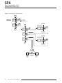
Main Menu/View Settings
The High Level Input SPA operating parameters are
set, and the settings are stored in on-board, nonvolatile EEPROM. There are four push buttons on
the unit front panel; VIEW, SELECT, an UP arrow,
and a DOWN arrow. Together with the prompting
messages displayed on the LCD, these are used to
access menus, and to view and change the settings
for:
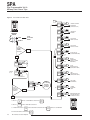
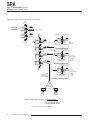
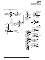
Figure 5 gives an overview of the first level of menus
used to configure the SPA.
• Select Input Type: current (I) or voltage (V)
• Select Functional Setting (Linear Mode or
Custom Mode) and, if selected, set Custom
Mode Engineering units.
On power-up, the SPA defaults to a display of the
measured value. Pressing the VIEW button
accesses a series of displays that show, in
succession, the settings currently stored in unit
memory (see Figure 6).
Depending upon whether or not the Security Jumper
has been installed (see Figure 2), SELECT will
access either the first screen in the main
configuration menu, “SEL V/I”, or the password code
query screen, “ENTR PASS”.
• Scale Input — Smart Scaling
• Apply Input — Bench Scaling
• Scale Display readout
• Set Linearization Curve (Custom Mode only)
Once the Main Menu has been accessed, the up and
down arrow buttons are used to move through all of
the sub-menus in a loop. Pressing the SELECT
button accesses the first screen of the sub-menu
shown on the LCD.
• Scale Analog Output (AO-equipped units only)
• Trim Analog Output (AO-equipped units only)
• Configure Alarm Functions (Trip points, etc.)
• Change/View Password
The Interface Solution Experts
9
SPA
Site-Programmable Volt &
Milliamp Limit Alarm Trips
Figure 5. The HLPRG SPA Main Menu
CONF
EXIT
000.0
DEG C
SEL
V/I
VIEW
SELECT
CONF
OPTS
VIEW
SELECT
SCLE
INPT
VIEW
SELECT
APLY
INPT
VIEW
SELECT
SCLE
DSPL
VIEW
SELECT
ENTR
CURV
VIEW
SELECT
ENTER
LINEARIZING
CURVE (CUSTOM
MODE ONLY)
SCLE
AO
VIEW
SELECT
SCALE
ANALOG OUTPUT
(AO-EQUIPPED ONLY)
TRIM
OUT
VIEW
SELECT
TRIM
ANALOG OUTPUT
(AO EQUIPPED ONLY)
VIEW
CHOOSE CURRENT
OR VOLTAGE
(DEFAULTS TO mA)
SELECT
DISPLAY OF
PROCESS
VALUE
VIEW
SETTINGS
MODE
VIEW
CONFIGURE
OPTIONS
SCALE INPUT
"SMART SCALING"
SELECT
IS THE
SECURITY
JUMPER
INSTALLED?
APPLY INPUT
"BENCH SCALING"
NO
SCALE DISPLAY
(CUSTOM MODE ONLY)
YES
2 1
VIEW
SELECT
ENTER
PASS
INCREASE ##
DEFAULT
IS "55"
VIEW
SELECT
##
PASS
3
DECREASE ##
READ
ONLY
IS THE
DISPLAYED
PASSWORD
CORRECT?
VIEW
SELECT
READ,
BUT DO NOT
CHANGE
CURRENT
SETTINGS
4
CONF
ALRM
VIEW
SELECT
PASS
WORD
VIEW
SELECT
CONF
EXIT
VIEW
SELECT
NO
YES
1 SKIPS TO
SCLE
AO
2 SKIPS TO
CONF
ALRM
UNLESS CUSTOM MODE IS SELECTED IN
CHANGE
PASSWORD
CODE
EXIT MAIN MENU AND
RETURN TO DISPLAY
OF PROCESS VALUE
000.0
DEG C
VIEW
UNLESS AO OPTION IS INSTALLED
3 UP FROM HERE SKIPS TO
ENTR
CURV
UNLESS AO OPTION IS INSTALLED, OR TO
4 IN READ ONLY MODE SCREEN SHOWS
10
CONF
OPTS
SET ALARM
PARAMETERS
The Interface Solution Experts
PASS
LOCK
SELECT
SCLE
DSPL
UNLESS IN CUSTOM MODE
SPA
Site-Programmable Volt &
Milliamp Limit Alarm Trips
Password
Figure 6. The HLPRG SPA View Mode
This menu is bypassed if the Password Security
Jumper is not installed (see Figure 2). If the jumper
is installed, the menu comes up when SELECT is
pressed from the display of the process variable
input. The flow chart is shown as part of Figure 5.
I
000.0
DEG C
VIEW
SELECT
I
1. If the jumper is installed, pressing
SELECT from the display of the process
variable input will bring up the “ENTR
PASS” screen.
SELECT
2. Use the up or down arrow buttons, or
press SELECT again to access “55
PASS”, the default screen for this point in
the menu.
IS THE
SECURITY
JUMPER
INSTALLED?
3. Use the up or down arrow buttons to
display the correct password.
NO
MAIN
MENU
(FIGURE 6)
YES
When the correct password number is
displayed, press SELECT.
PASSWORD
MENU
(FIGURE 6)
NOTE:
If the correct password is not known, the unit
settings can be viewed, but not changed, as
shown in Figure 17.
4. If you have entered the correct password,
the Select Input Type menu, “SEL V/I”, will
be accessed. If not, the display will show
a “READ ONLY” message.
5. From “READ ONLY”, press SELECT to
view the settings in the various menus.
READ ONLY mode locks out any attempt
to make changes to the settings.
ZERO SETTING
IN MEMORY
####
ZERO
VIEW
SELECT
FULL SCALE SETTING
IN MEMORY
####
FULL
VIEW
SELECT
TRIP POINT & HI/LO
ALARM SETTINGS
FOR RELAY #1
####
AL1x
VIEW
SELECT
Press the up or down arrow buttons to
return to “55 PASS” from “READ ONLY”.
IS
ANOTHER
ALARM
INSTALLED?
NOTE:
The menu to set or change the Password
stored in SPA memory is presented later in
this section of the manual.
I
VIEW
SETTINGS
MODE
VIEW
YES
NO
EXIT VIEW SETTINGS MODE
AND RETURN TO DISPLAY
OF PROCESS VALUE
I
SHOWS
PARAMETERS
OF NEXT RELAY
####
AL#x
VIEW
SELECT
The Interface Solution Experts
11
SPA
Site-Programmable Volt &
Milliamp Limit Alarm Trips
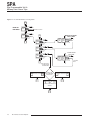
Select Input Type
Figure 7. Selecting the HLPRG Input Type
The menu for selecting the input type for the High
Level SPA is shown in Figure 7.
CONF
EXIT
If the Password Jumper is not installed, the
password sub-menu is bypassed, and the Select V/I
menu is accessed by pressing SELECT from the
display of the measured input value.
I
FROM THE
MAIN MENU
VIEW
SELECT
SEL
V/I
MA
0 50
VOLT
0 10
DEFAULTS TO
LAST SETTING
CONF
OPTS
VOLT
0 10
TOGGLE
VIEW
SELECT
MA
0 50
I
1. From the “SEL V/I” display, press
SELECT.
VOLT
0 10
3. When the display shows the type of input,
current or voltage, that is to be used with
the SPA, press SELECT.
4. The next display is the menu for the
selection of functional options, ”CONF
OPTS”. To skip the rest of the
configuration menus and return to the
display of the measured input value, press
the up arrow button 2 times (to “CONF
EXIT”), and press SELECT.
12
I
The Interface Solution Experts
MA
0 50
RETURNS TO MAIN MENU
2. Use the up or down arrow buttons to
scroll through the two options for input
type. The default display for this menu is
always the last setting.
I
TOGGLE
SPA
Site-Programmable Volt &
Milliamp Limit Alarm Trips
2. Press SELECT again to set the desired
function mode, or use the arrow buttons to
move to “EXIT OPT” and bypass the
Select Options procedure.
Configure Function Options
This menu allows the user to choose between Linear
and Custom modes of functioning.
Note that, depending upon the Mode
setting, it may be necessary to bypass
“SET LIN” screen.
Linear Function. In its Linear Mode, the HLPRG
SPA behaves much like a simple input meter. The
display is set by the user to show the input in either
mA or volts. Its scaling is tied to any input scaling
performed (set in another menu). If equipped with
one of the AO options, SPA output also can be
scaled independently with respect to the input.
3. With “SET FUNC” showing on the LCD,
use the arrow buttons to toggle between
“CUST FUNC” and “LINR FUNC”. Refer
to the explanation above for information
about each of the operating modes.
Custom Function. The HLPRG’s Custom Mode
sets the unit up for independent programming of
input scaling, display scaling, and, if equipped with
the AO option, output scaling. In Custom Mode, the
user can select °C, °F, % of scale, or Blank (for raw
display); or a user-specified, 4-place engineering
unit, set at the factory.
4. When the LCD shows the desired mode,
press SELECT.
5. If “CUST FUNC” was selected, go to
step 7.
6. If “LINR FUNC” was selected, the LCD
will now show “EXIT OPTS”.
Also, if Custom Mode is selected, the user can
select either linear or non-linear display scaling,
which enables a user-programmed, 20-point
linearization set in a separate menu.
Use the arrow buttons to return to “SET
FUNC” (step 3), or press SELECT to
return to the Main Menu.
7. Press SELECT to begin the process of
setting the desired engineering units to be
displayed during HLPRG operation.
NOTE:
The SPA’s Linear Mode and its linearizing of
the Custom Mode functioning are not the
same. Refer to Figure 8.
8. Use the arrow buttons to “scroll” through
the available options.
Figure 8 gives an overview of the HLPRG SPA
Configure Options menu.
I
9. When the appropriate units are showing
on the LCD, press SELECT.
This brings up a sub-menu that allows the
user to choose between a linearized or
non-linearized display of the selected,
custom engineering units.
I
1. From the “CONF OPTS” screen of the
Main Menu, press SELECT. This brings
up “SET FUNC”, which is the access
screen for choosing between Linear and
Custom Function Modes.
10. Use the arrow buttons to toggle
linearization on or off, then press SELECT
to go to “EXIT OPTS”.
11. Press SELECT again (from “EXIT
OPTS”) to return to the Main Menu, or to
correct any mistake, go to step 2.
I
I
The Interface Solution Experts
13
SPA
Site-Programmable Volt &
Milliamp Limit Alarm Trips
Figure 8. The HLPRG SPA Configure Options Menu
CONF
EXIT
VIEW
SELECT
SEL
V/I
CHOOSE CURRENT
OR VOLTAGE
(DEFAULTS TO mA)
LINR
FUNC
EXIT
OPT
VIEW
SELECT
CONF
OPTS
CUST
FUNC
SELECT
CUST
FUNC
VIEW
SELECT
SET
FUNC
CUST
FUNC
VIEW
SELECT
LINR
FUNC
VIEW
SELECT
SET
EGU
?
LINR
FUNC
SCLE
INPT
CUST
FUNC
LINR
FUNC
SELECT
EXIT
OPTS
WHAT IS THE
FUNCTION MODE
OF THE UNIT?
DEGC
VIEW
SELECT
DEGF
VIEW
SELECT
PCT
VIEW
SELECT
BLNK
VIEW
SELECT
CSTM
VIEW
SELECT
CUST
FUNC
LINR
FUNC
EXIT
OPTS
SET
FUNC
CUST
CONF
OPTS
LIN
OFF
SET
LIN
VIEW
SELECT
EXIT
OPTS
VIEW
SELECT
CONF
OPTS
LIN
ON
LIN
ON
VIEW
SELECT
LIN
OFF
LIN
ON
LIN
OFF
EXIT
OPTS
RETURN TO
THE MAIN MENU
DEGC
14
The Interface Solution Experts
SPA
Site-Programmable Volt &
Milliamp Limit Alarm Trips
Scaling Input —
“Smart Scaling” the HLPRG
Figure 9 shows the Smart Scaling menu.
This feature of the HLPRG SPA allows users to set
the zero and full scale values of the input from the
intended application without having to connect the
unit to any calibration equipment.
I
I
1. From the readout of “SCLE INPT” on the
Main Menu, press SELECT.
2. Use the arrow buttons to “scroll” from
“SET ZERO” to “SET FULL”, or to “EXIT
SCLE” to abort Smart Scaling and return
to the Main Menu.
With Smart Scaling, the LCD and menus are used to
enter the value for zero and full scale, in either
milliamps or volts.
3. When the desired parameter shows on
the LCD, press SELECT.
Once these two input parameters are set, the
HLPRG automatically routes the user to the next
appropriate menu; Scale the Display, for Custom
Mode users; Scale the Output, for Linear Mode users
(with AO-equipped HLPRG SPAs); or Configure
Alarms, for Linear Mode users whose units are not
equipped with analog output.
The LCD will show the engineering units
selected in Configure Options menu,
discussed previously in this section.
4. Use the arrow buttons to set the display to
show the known zero or full scale input
from the intended application. Holding the
push button in accelerates the display
change.
5. When the LCD shows the correct setting,
press SELECT.
6. If “EXIT SCLE” is showing and both zero
and full scale have not been set, go to
step 2.
7. If both the zero input and full scale input
parameters have been entered into the
SPA memory, go to step 9.
8. Go to step 4.
9. Use the arrow buttons to “scroll” to “EXIT
SCLE” and press SELECT.
If the SPA Custom Mode was selected in
the Configure Options menu, the next
menu shown will be Scale the Display,
since in Custom Mode the input, display,
and output (if present) are independent.
If the SPA Linear Mode was selected in
the Configure Options menu, the next
menu shown will either be Scale Analog
Output, for units equipped with an AO
option, or Configure Alarms.
I
I
The Interface Solution Experts
15
SPA
Site-Programmable Volt &
Milliamp Limit Alarm Trips
Figure 9. Smart Scaling the HLPRG SPA Input
SEL
V/I
FROM THE
MAIN MENU:
CONF
OPT
VIEW
SELECT
SCLE
INPT
VIEW
SELECT
APLY
INPT
SET LINEAR
OR CUSTOM
ENGINEERING UNITS
INCREMENT
XXXX (ZERO)
EXIT
SCLE
SET
ZERO
DEFAULTS TO
LAST SELECTED
XXXX
MA
VIEW
SELECT
XXXX
VOLT
VIEW
SELECT
DECREMENT
XXXX (ZERO)
SET
FULL
VIEW
SELECT
INCREMENT
XXXX (FULL)
EXIT
SCLE
DEFAULTS TO
LAST SELECTED
VIEW
SELECT
XXXX
MA
XXXX
VOLT
SET
ZERO
DECREMENT
XXXX (FULL)
WAS
CUST
FUNC
SELECTED
IN
YES
SCLE
DSPL
16
The Interface Solution Experts
CONF
OPT
?
EXIT INPUT SCALING
AND RETURN TO
MAIN MENU
NO
SCLE
AO
VIEW
SELECT
SPA
Site-Programmable Volt &
Milliamp Limit Alarm Trips
Applying Input —
“Bench Ranging” the HLPRG
I
I
1. From the “APLY INPT” point of the
HLPRG SPA Main Menu, press SELECT.
With this method of calibrating input to the SPA, the
inputs are “captured” at their zero and full scale
levels.
2. Use the arrow buttons to bring up the
desired parameter, Save Zero, Save Full,
or Exit Input to abort the Bench Ranging
procedure.
Figure 10 shows the setup required for applying and
capturing input scaling for the HLPRG SPA. After
the connections shown in the diagram have been
made, apply appropriate power and allow
approximately 5 minutes for unit warm-up/
stabilization.
3. When the appropriate display for the
parameter to be input is showing on the
LCD, press SELECT.
The display will show the engineering
units selected in the Configure Options
menu, discussed earlier in this section.
Figure 11 shows the SPA menu used in this
procedure.
Figure 10. The HLPRG SPA Bench Scaling Setup
4. Vary the input to either the zero or full
scale level from the intended application.
5. When the display shows the appropriate
readout, press SELECT to capture the
value in the HLPRG SPA memory.
_
VOLTAGE
SOURCE +
6. Repeat steps 2 through 5 until both the
zero and full scale values from the
intended application have been captured.
_
CURRENT
SOURCE +
7. If the SPA has been set up to operate in
Linear Mode and no analog output option
is present, go to step 10.
8. If the SPA has been set up to operate in
Linear Mode and an analog output option
is present, go to step 11.
9. If neither step 7 or 8 apply, use the arrow
buttons to bring up the “EXIT INPT”
display from step 5, and press SELECT to
return to the Main Menu at the Scale
Display point.
VIEW
SELECT
AC OR DC
POWER
SUPPLY
SPA SITE-PROGRAMMABLE
ALARM
10. Use the arrow buttons to bring up the
“EXIT INPT” display from step 5, and
press SELECT to return to the Main Menu
at the Configure Alarm(s) point.
GND
11. Use the arrow buttons to bring up the
“EXIT INPT” display from step 5, and
press SELECT to return to the Main Menu
at the Scale Output point.
I
I
The Interface Solution Experts
17
SPA
Site-Programmable Volt &
Milliamp Limit Alarm Trips
Figure 11. The HLPRG SPA Bench Scaling Menu
CONF
OPTS
FROM THE
MAIN MENU:
SCLE
INPT
VIEW
SELECT
APLY
INPT
VIEW
SELECT
SCLE
DSPL
"SMART" SCALING
DISPLAY FLASHES
INPUT LEVEL
EXIT
INPT
SAVE
ZERO
VIEW
SELECT
SAVE
FULL
VIEW
SELECT
EXIT
INPT
VIEW
SELECT
XXXX
MA
VIEW
SELECT
XXXX
VOLT
DISPLAY FLASHES
INPUT LEVEL
XXXX
MA
VIEW
SELECT
XXXX
VOLT
CAPTURES
INPUT
SAVE
ZERO
EXIT APPLY INPUT
AND RETURN TO
THE MAIN MENU
LINR
WAS SELECTED IN
WHAT IS THE
FUNCTION MODE
OF THE UNIT?
CONF
OPTS
CSTM
SCLE
DSPL
CONF
ALRM
LINR
WAS SELECTED IN
AND
UNIT IS EQUIPPED
WITH AO
SCLE
AO
18
The Interface Solution Experts
WAS SELECTED IN
CONF
OPTS
CONF
OPTS
SPA
Site-Programmable Volt &
Milliamp Limit Alarm Trips
Scaling the Display —
Setting the Engineering Units
in Custom Mode
I
I
1. From the “SCLE DSPL” screen of the
Main Menu, press SELECT.
This is the menu with which the HLPRG SPA user
can further “customize” unit operations. This menu
is available only in units where the “CUST FUNC”
Custom Mode selection has been made in the
Configure Options menu, earlier.
2. Use the arrow buttons to “scroll” through
the parameters for scaling the display:
• Set the decimal position
• Set the displayed zero
• Set the displayed full scale
• Exit the Display Scaling procedure and
return to the Main Menu
NOTE:
The settings for decimal place and zero and
full scale display that are entered into SPA
memory are saved as numeric values as
opposed to percentages.
They are independent of settings for input
scaling and trip points.
3. When the parameter that is to be set is
showing on the LCD, press SELECT.
4. Refer to Figure 12 for information on the
function of the up and down arrow buttons
for each of these parameters.
If changes are made to the Input Scaling or
Trip Points (in the Configure Alarms menu),
this menu must be accessed and the values
changed appropriately in order to carry any
scaling changes through to the display.
5. When the parameter has been set
appropriately for the intended application,
make a note of the scaling for future
reference, and press SELECT.
6. Repeat steps 2 through 5 until all
parameters for the display have been set
as required.
Figure 12 shows the menu for this procedure.
7. With “EXIT DSPL” showing on the LCD,
press SELECT to return to the Main
Menu.
I
I
The Interface Solution Experts
19
SPA
Site-Programmable Volt &
Milliamp Limit Alarm Trips
Figure 12. Scaling the HLPRG SPA Display in Custom Mode
SCLE
INPT
FROM THE
MAIN MENU:
APLY
INPT
VIEW
SELECT
SCLE
DSPL
VIEW
SELECT
ENTR
CURV
SMART SCALING
SHIFTS DECIMAL TO THE RIGHT
EXIT
DSPL
XXXX
VOLT
VIEW
SELECT
SET
DP
VIEW
SELECT
SETS
DECIMAL
POSITION
SHIFTS DECIMAL TO THE LEFT
DSPL
ZERO
VIEW
SELECT
DSPL
FULL
VIEW
SELECT
INCREMENTS SCALED
ZERO DISPLAY
XXXX
EGU
VIEW
SELECT USES THE
UNITS CHOSEN
IN CNFG
DECREMENTS SCALED
ZERO DISPLAY
VIEW
SELECT
EXIT
DSPL
OPTS
INCREMENTS SCALED
FULL DISPLAY
SET
DP
XXXX
EGU
UNITS CHOSEN
IN CNFG
EXIT
SCALE DISPLAY
AND RETURN TO
THE MAIN MENU
DECREMENTS SCALED
FULL DISPLAY
IS THE
AO OPTION
INSTALLED?
YES
NO
ENTR
CURV
CONF
ALRM
NOTE: MAXIMUM DISPLAY RANGE* =
INPUT RANGE
INPUT ACCURACY
(1mV FOR VOLTAGE INPUTS
5mA FOR CURRENT INPUTS)
*DISPLAY FULL SETTING – DISPLAY ZERO SETTING
20
The Interface Solution Experts
VIEW
SELECT USES THE
OPTS
SPA
Site-Programmable Volt &
Milliamp Limit Alarm Trips
or
Programming SPA Linearization —
Entering Segment Endpoints
in Custom Mode
Press the down arrow button to bring up
the “ENTR PNT” screen. Pressing
SELECT will bring up a screen allowing
you to enter a particular point that is to be
changed, assuming that the curve has
been entered previously.
From this menu the user can program up to 20
linearization points into non-volatile HLPRG SPA
memory. This capability works exclusively with the
unit’s Custom Mode to make the SPA display linear
with respect to its scaled input. When enabled (in
the “CONF OPTS” menu, discussed earlier), the
SPA’s Custom Mode sets the unit to display the
linearized input value in the user-set engineering
units.
The “rules” for entering points are:
• Xz < Xn < Xn+1 < Xn+2 < ... < Xn+19 < Xf
Where Xz=Input zero, in this case, 0mA;
and Xf=Input full scale, in this case, 50mA;
Xn, Xn+1 through Xn+19 = Input curve
As mentioned, the “ENTR CURV” menu is active only
when the SPA’s “CUST FUNC” Custom Mode
selection has been made in the Configure Options
menu.
• Yz < Yn < Yn+1 < Yn+2 < ... < Yn+19 < Yf
Where Yz=Display zero, in this case, 0%:
and Yf=Display full scale, in this case, 100%;
Yn, Yn+1 through Yn+19 = Display curve
IMPORTANT:
Input zero and full scale as well as display
zero and full scale must be programmed prior
to programming the linearization curve.
NOTE:
The endpoints of the curve must
fall within a range defined by the zero and full
scale values for both the input and the display
(see the graph, below).
The procedure consists of defining the number of
points that are to constitute the linearization curve,
then specifying first the input, then its corresponding
display value at each point. Figure 13 shows the
menu.
I
1. Make sure that the zero and full scale
values have been entered into memory
for:
DI SPLAY
I
FULL
SCALE
ALL POINTS MUST FALL BETWEEN
ZERO AND FULL SCALE OF BOTH
DISPLAY AND INPUT SCALING.
• Input scaling (“smart” scaling) or input
capturing (bench scaling)
• Display scaling
• Analog Output (if present)
2. From the “ENTR CURV” point of the main,
HLPRG SPA menu, press SELECT.
3. Press SELECT from the next screen,
“NUMB PNTS”, to bring up a screen for
entering the number of points to be used
in the linearization curve.
0
INPUT
FULL
SCALE
4. When the display shows the point number
that is to be programmed, press SELECT.
The Interface Solution Experts
21
SPA
Site-Programmable Volt &
Milliamp Limit Alarm Trips
Figure 13. Entering the Linearization Points for the SPA in Custom Mode (only)
FROM THE
MAIN MENU:
APLY
INPT
VIEW
SELECT
SCLE
DSPL
RETURN TO
MAIN MENU
SCALE THE LCD
READOUT OF THE
INPUT
SCLE
AO
OR
CONF
ALRM
ENTR
PNT
VIEW
SELECT
ENTR
CURV
EXIT
CURV
VIEW
SELECT
NUMB
PNTS
VIEW
SELECT
SCLE
AO
OR
CONF
ALRM
VIEW
SELECT
ENTR
PNT
INCREASE # OF
POINTS TO BE USED
IN CURVE (1-20)
##
PNTS
VIEW
SELECT
DECREASE # OF
POINTS TO BE USED
IN CURVE (1-20)
NEXT POINT
EXIT
CURV
PNT
##
YES
INCREMENT INPUT VALUE
VIEW
SELECT
####
MA/V
INCREMENT DISPLAY
VALUE IN ENGINEERING
UNITS
VIEW
SELECT
####
------
VIEW
SELECT
NEXT POINT
DECREMENT INPUT VALUE
MORE
POINTS?
DECREMENT DISPLAY
VALUE IN ENGINEERING
UNITS
NO
5. Use the arrow buttons to set the desired
INPUT VALUE for the first point. Note
that the default units are those selected in
the “SEL V/I” menu, mA or V.
8. When the display shows the desired
value, press SELECT.
9. The SPA automatically brings up the
screen “PNT ##” for the next point to be
programmed (if the “NUMB PNTS” value
was changed), or returns to the “ENTR
PNT” screen to allow the user to select
the next point. From “ENTR PNT” the
user can also exit to the main menu.
6. When the display shows the desired
value, press SELECT.
7. The next screen prompts for the value
that the DISPLAY is to show at the input
level just programmed (steps 5 and 6).
NOTE:
When programming linearization points, the
LCD will flash if an attempt is made to enter an
“illegal” point.
Use the arrow buttons to program the
desired value. Note that the default units
here are those that were set in the “CONF
OPTS” menu.
10. Refer to the following example for further
clarification.
I
22
The Interface Solution Experts
I
SPA
Site-Programmable Volt &
Milliamp Limit Alarm Trips
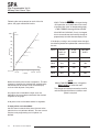
EXAMPLE Programming an HLPRG Linearization Curve
Following the instructions is step 1 on the preceding
page, a SPA is set up with the following parameters:
• Xz < Xn < Xn+1 < Xn+2 < ... < Xn+19 < Xf
Where Xz=Input zero, in this case, 0mA;
and Xf=Input full scale, in this case, 50mA;
Xn, Xn+1 through Xn+19 = Input curve
• 0-50mA input
(“SEL V/I”, and “SCLE INPT” or “APLY INPT”)
• Yz < Yn < Yn+1 < Yn+2 < ... < Yn+19 < Yf
Where Yz=Display zero, in this case, 0%:
and Yf=Display full scale, in this case, 100%;
Yn, Yn+1 through Yn+19 = Display curve
• 0-100% LCD readout
(“PCT” in “CUST FUNC” under “CONF OPTS”, and
000.0 for zero, 100.0 for full scale in “SCLE DSPL“)
Use a graph to show the relationship between INPUT
and DISPLAY:
100%
full
scale
90
From steps 2 and 3 of the procedure, 5 points
between 0 and 50mA are chosen.
“5” is entered in the “NUMB PNTS” screen. When
SELECT is pressed, the “PNT 01” screen appears.
Pressing select, the arrow buttons are used to enter
the first input point, which, in this example is to be
10mA.
80
When SELECT is pressed, we are prompted for the
DISPLAY at point 01, which, in this example, we
want to be 20%. Our graph would look like this for
point 01:
DI SPLAY
70
60
50
40
30
100%
20
full
scale
90
10
full
scale
80
0%,0mA
I NPUT
70
40mA 50mA
As shown, plot the INPUT points along the X axis,
and the DISPLAY points along the Y axis.
The “rules” for inputting linearization points are as
follows:
DI SPLAY
10mA
60
50
40
30
20
X
10
full
scale
0%,0mA
10mA
I NPUT
40mA 50mA
The Interface Solution Experts
23
SPA
Site-Programmable Volt &
Milliamp Limit Alarm Trips
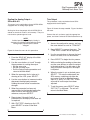
Following the menu prompts for each of the five
points, the graph would look like this:
full
scale
100%
X
90
80
X (40mA, 80%)
DI SPLAY
70
60
NOTES:
If INPUT SCALING (X-axis) is changed, during
SPA operation, to fall within the curve values
(violation of the “rules” on the preceding page),
a TABLE ERROR message will be returned.
If the DISPLAY SCALING (Y-axis) is changed,
the curve coordinates automatically change to
proportionally fall within the new display scale.
If the display scaling in our example were changed,
the following would be implemented automatically by
the unit:
X (30mA, 60%)
50
INPUT
INITIAL
DISPLAY
SCALE
0-750
UNITS
500-1000
UNITS
10mA
20%
150
600
20mA
40%
300
700
30mA
60%
450
800
40mA
80%
600
900
X (25mA, 50%)
40
X (20mA, 40%)
30
20
X (10mA, 20%)
10
full
scale
0%,0mA
10mA
I NPUT
40mA 50mA
Notice that the 5 points create 4 segments. The end
segments, shown by the dashed lines are defined by
the coordinates of the input scale and the display
scale and the adjacent curve points.
Any inputs that fall outside the input scale are
defined by the same slope and offset of the dashed
segments in the graph.
A 20-point curve can therefore define 21 segments.
If more points are to be added...
the SPA menu automaticalles takes the user to the
point that has not yet been defined. The user cannot
exit the curve programming until all points are
defined.
24
The Interface Solution Experts
NOTE:
When a TABLE ERROR occurs, change the
INPUT SCALE to “follow the rules”.
The change will not be processed by the SPA
until the Configuration menu is exited, or until
power is recycled.
SPA
Site-Programmable Volt &
Milliamp Limit Alarm Trips
Scaling the Analog Output —
SPAs with AO
Trim Output
This procedure is only required on those SPAs
equipped with the AO option.
This menu is only applicable to those HLPRG SPAs
equipped with an analog output option.
Scaling for the analog output of the HLPRG SPA is
stored as numerical values in unit memory. They are
not stored as percentages of scale.
NOTE:
If either Input Scaling or Display Scaling is
changed, any existing scaling operating on the
analog output (if present) must also be
changed.
Figure 15 shows the setup needed. Figure 16 shows
the menu.
Connect the unit as shown, apply the appropriate
power, and allow 5 minutes for stabilization/warm-up.
I
1. Access the configuration menus, and use
the arrow buttons to scroll to “TRIM OUT”.
2. Press SELECT to access the menu. The
“TRIM ZERO” screen will be displayed.
Figure 14 shows the menu for this procedure.
I
I
3. Use the arrow buttons to choose the level,
zero or full scale, that is to be trimmed.
I
1. From the “SCLE AO” display of the Main
Menu, press SELECT.
4. Press SELECT to begin the trim process.
2. Use the arrow buttons to “scroll” through
the parameters for scaling the output:
• Set the zero value
• Set the full scale value
• Exit the Output Scaling procedure and
return to the Main Menu
5. While monitoring the reading on the meter,
use the arrow buttons to adjust the output
to the desired level. Use the meter in the
setup to monitor the output as the output
is adjusted.
6. When the output is set as desired, press
SELECT. This sets the adjustment into
SPA memory, and brings up either the
next output level to be adjusted (repeat
steps 3, 4, and 5), or “EXIT OUT” if both
zero and full scale output have been
adjusted.
3. When the parameter that is to be set is
showing on the LCD, press SELECT.
4. Use the arrow buttons to increment and/or
decrement the displayed parameter.
Holding the arrow button in accelerates
changes.
7. To exit the menu, press SELECT when
“EXIT OUT” is displayed. The unit will
return to the Main Menu.
5. When the parameter has been set
appropriately for the intended application,
make a note of the scaling for future
reference, and press SELECT.
I
I
6. Repeat steps 2 through 5 until all
parameters for the display have been set
as required.
7. With “EXIT Z/FS” showing on the LCD,
press SELECT to return to the Main
Menu.
I
I
The Interface Solution Experts
25
SPA
Site-Programmable Volt &
Milliamp Limit Alarm Trips
Figure 14. Scale HLPRG SPA Analog Output (AO-equipped units only)
FROM THE
MAIN MENU:
APLY
INPT
SCLE
DSPL
VIEW
SELECT
SCLE
AO
VIEW
SELECT
TRIM
OUT
"SMART" SCALING
INCREMENTS
OUTPUT ZERO
EXIT
Z/FS
SET
ZERO
DEFAULTS TO
LAST SELECTED
VIEW
SELECT
XXXX
MA
XXXX
VOLT
VIEW
SELECT
DECREMENTS
OUTPUT ZERO
SET
FULL
VIEW
SELECT
INCREMENTS
OUTPUT FULL SCALE
VIEW
SELECT
EXIT
Z/FS
XXXX
MA
SET
ZERO
EXIT
SCALE OUTPUT
AND RETURN TO
THE MAIN MENU
XXXX
VOLT
VIEW
SELECT
DECREMENTS
OUTPUT FULL
SCALE
NOTE: RE-RANGING THE UNIT NULLIFIES ANY OUTPUT TRIM. RE-TRIM AFTER ANY RE-RANGING.
26
The Interface Solution Experts
SPA
Site-Programmable Volt &
Milliamp Limit Alarm Trips
Figure 15. Connections for Trimming SPA Output
(AO-equipped units only)
VOLTAGE
SOURCE
Figure 16. Trimming the SPA Analog Output
(AO-equipped units only)
TRIM
OUT
_
SCLE
AO
VIEW
+
MULTIMETER
OR
MILLIAMETER
+ _
_
CURRENT
SOURCE +
SELECT
CONF
ALRM
TRIM
ZERO
EXIT
OUT
VIEW
_
+
SELECT
TRIM
FULL
READY
TRIP 1
INPUT
TRIP 2
TRIM
ZERO
VIEW
INCREMENT
SELECT
DECREMENT
VIEW
SELECT
AC OR DC
POWER
SUPPLY
GND
SPA
SITE-PROGRAMMABLE
ALARM
TRIM
ZERO
TRIM
FULL
VIEW
SELECT
EXIT
OUT
TRIM
FULL
INCREMENT
VIEW
DECREMENT
SELECT
EXIT
OUT
TRIM
FULL
TRIM
ZERO
VIEW
SELECT
CONF
ALRM
MAIN MENU
The Interface Solution Experts
27
SPA
Site-Programmable Volt &
Milliamp Limit Alarm Trips
NOTES:
There are two options for setting the trip points
of the installed alarms,
“ENTR TRIP” and “APLY TRIP”.
Configure Alarm(s)
This menu sets:
• Trip Point(s)
In the “ENTR TRIP” menu, the user employs
the Smart Ranging feature of the SPA,
entering the desired trip point with the
front panel push buttons.
(Steps 4 through 6)
• Deadband(s)
• Trip Delay(s)
• High Alarm or Low Alarm Function
In the “APLY TRIP” menu, the SPA must be
set up with calibration equipment (see Figure
21, page 37). In this, the Standard Ranging
procedure, the unit “captures” its trip point from
the input of an adjustable source.
(Steps 7 through 14)
• Latching or Non-Latching Operation
Figure 17 gives the menu overview.
I
I
1. From the “CONF ALRM” screen of the
Main Menu, press SELECT.
2. Press SELECT again to access the
settings for the first installed alarm, or use
the arrow buttons to access the “ALRM
EXIT” screen. Pressing SELECT from
“ALRM EXIT” returns to the Main Menu at
“PASS WORD”.
3. Use the arrow buttons to scroll through
the alarm operation parameters.
Press SELECT to access the settings for
the displayed parameter.
For convenience, it is recommended that
the settings be entered into SPA memory
in the order that they come up in this step
(shown in Figure 17 from top to bottom):
• Enter/Apply Trip
• Enter Deadband
• Enter Delay
• Set High Alarm or Low Alarm Functioning
• Set Latching or Non-Latching
• Exit
28
The Interface Solution Experts
ENTER TRIP
If the value of the trip point is known, use
this, the Smart Ranging feature, of the
SPA to program the value into SPA
memory. If the trip point is not known, or
cannot be entered numerically, skip to
step 7, APPLY TRIP.
4. From “ENTR TRIP” in step 3, press
SELECT.
NOTE:
When the HLPRG is in Linear Mode, the
display will show either mA or V.
When in Custom Mode, the display will show
the engineering units set in the CONF OPTS
menu, Figure 8.
5. Use the arrow buttons to ramp the display
to the trip point value, and press SELECT.
This enters the displayed value into SPA
memory, and brings up the “ENTR DB”
(enter deadband) display.
6. Skip to step 14.
SPA
Site-Programmable Volt &
Milliamp Limit Alarm Trips
Figure 17. Configuring the HLPRG SPA Alarms
TRIM
OUT
FROM THE
MAIN MENU:
ALRM
EXIT
CONF
ALRM
EXIT
ALRM
AL 1
CONF
ENTR
TRIP
INCREASE
TRIP POINT
####
XXXX
DECREASE
TRIP POINT
PASS
WORD
APLY
TRIP
HIGHEST
NUMBERED
INSTALLED
ALARM
DISPLAY FLASHES
ENGINEERING
UNITS AND DECIMAL
POSITION SET
IN CONF OPTS
AL #
CONF
IS
ANOTHER
ALARM
INSTALLED?
NO
DISPLAYS
ENGINEERING UNITS
AND DECIMAL POSITION
SET IN CONF OPTS
####
XXXX
YES
AL #
CONF
NEXT HIGHEST
NUMBERED
INSTALLED ALARM
AL #
CONF
INCREASE
DEADBAND
AL #
CONF
DISPLAYS
ENGINEERING UNITS
AND DECIMAL POSITION
SET IN CONF OPTS
####
XXXX
ALRM
EXIT
EXIT CONF ALARM
MENU AND RETURN
TO MAIN MENU PASS
ENTR
DB
DECREASE
DEADBAND
WORD
INCREASE DELAY
AL 1
CONF
ENTR
DLY
##
SECS
0-60
SECONDS
DECREASE DELAY
HIGH ALARM/LOW ALARM
SET
HILO
XXX
ALRM
SET
LAT
HIGH ALARM/LOW ALARM
LATCHING/NON-LATCHING
EXIT
ALRM
XXX
LAT
LATCHING/NON-LATCHING
ENTR
TRIP
The Interface Solution Experts
29
SPA
Site-Programmable Volt &
Milliamp Limit Alarm Trips
APPLY TRIP
A signal can be applied to the input
terminals of the SPA, using the setup
shown in Figure 10. With this setup and
the following procedure, the unit can
“capture” the desired trip point.
7. Install the SPA being configured into the
setup shown in the figure, apply
appropriate power, and allow
approximately 5 minutes for stabilization/
warm-up.
8. Access the configuration menus, and use
the down arrow to access the “CONF
ALRM” menu.
9. Press SELECT.
10. Use the arrow buttons to access “APLY
TRIP”.
11. Press SELECT. The display will flash the
input level present at the terminals.
12. Adjust the input to the desired trip point
level.
13. Press SELECT when the flashing value
on the display reaches the desired trip
point value. This stores the value in SPA
memory and returns the unit to the Alarm
Configuration menu at the “ENTR DB”
(enter deadband) screen.
Disconnect the SPA from the input.
14. Press SELECT to access the deadband
setting screen, or use the arrow buttons to
scroll through the other alarm operating
parameters. Press SELECT to access
the screen(s) for the parameter displayed,
or scroll to “EXIT ALRM” and press
SELECT to access the menus for another
alarm (if installed), or to return to the Main
Menu.
30
The Interface Solution Experts
ENTER DEADBAND
15. From the “ENTR DB” screen, press
SELECT.
16. Use the arrow buttons to increase or
decrease the deadband around the trip
point in SPA memory. The display will
show the value in the engineering units
selected in the “CONF OPTS” menu,
discussed earlier.
17. Press SELECT when the display shows
the desired deadband value. This returns
the unit to the Alarm Configuration menu
at the “ENTR DLY” (enter response
delay) screen.
18. Press SELECT to access the delay
setting screen, or use the arrow buttons to
scroll through the other alarm operating
parameters. Press SELECT to access
the screen(s) for the parameter displayed,
or scroll to “EXIT ALRM” and press
SELECT to access the menus for another
alarm (if installed), or to return to the Main
Menu.
ENTER DELAY
19. From the “ENTR DLY” screen, press
SELECT.
20. Use the arrow buttons to change the
amount of delay time between the input’s
exceeding the trip point setting and the
actual state change of the alarm. Settings
from 0 to 60 seconds are available in 1
second increments.
21. Press SELECT when the display shows
the desired delay setting. This returns the
unit to the Alarm Configuration menu at
“SET HILO” (choose high or low alarm
function).
SPA
Site-Programmable Volt &
Milliamp Limit Alarm Trips
22. Press SELECT to access the high/low
setting screen, or use the arrow buttons to
scroll through the other alarm operating
parameters. Press SELECT to access
the screen(s) for the parameter displayed,
or scroll to “EXIT ALRM” and press
SELECT to access the menus for another
alarm (if installed), or to return to the Main
Menu.
SET LATCHING/NON-LATCHING
27. From the “SET LAT” screen, press
SELECT.
28. Use the arrow buttons to toggle the alarm
function between latching (alarm stays
tripped until input returns to normal
(allowing for any deadband) AND unit is
manually reset) and non-latching (alarm
returns to normal as soon as input returns
to normal, allowing for any deadband)
function.
SET HI/LO
23. From the “SET HILO” screen, press
SELECT.
29. Press SELECT when the display shows
the desired setting. This returns the unit
to the Alarm Configuration menu at “EXIT
ALRM”.
24. Use the arrow buttons to toggle the alarm
function between high alarm operation
(trips when input exceeds the trip point
setting) and low alarm operation (trips
when input drops below the trip point).
30. Press SELECT to bring up the menu for
the next installed alarm. If no additional
alarms are installed, or to return to the
Main Menu, press SELECT from “EXIT
ALRM”.
25. Press SELECT when the display shows
the desired setting. This returns the unit
to the Alarm Configuration menu at “SET
LAT” (choose latching or non-latching
alarm function).
To set the operating parameters for the
next installed alarm, use the arrow buttons
from the “EXIT ALRM” screen to display
the next alarm, “AL2 CONF”, for example,
and press SELECT, and return to step 3.
26. Press SELECT to access the latch/no
latch setting screen, or use the arrow
buttons to scroll through the other alarm
operating parameters. Press SELECT to
access the screen(s) for the parameters
displayed, or scroll to “EXIT ALRM” and
press SELECT to access the menus for
another alarm (if installed), or to return to
the Main Menu.
When all of the alarm parameters for all of
the installed alarms have been set as
desired, press SELECT from “EXIT
ALRM”, and press SELECT again from
“ALRM EXIT”. This returns the unit to the
Main Menu at “PASS WORD”
I
I
The Interface Solution Experts
31
SPA
Site-Programmable Volt &
Milliamp Limit Alarm Trips
Change the Security Password Code
Figure 18. Changing the HLPRG SPA Password Code
This menu is active when the Security Jumper is
NOT installed, or when the jumper is installed and a
correct password has been entered. When the
jumper is installed, unless the correct password is
entered, accessing this menu causes the “PASS
LOCK” message to appear. Any attempt to make
changes will be “locked out” (READ ONLY mode).
PASS
WORD
CONF
ALRM
VIEW
SELECT
CONF
Z/FS
##
PASS
Figure 18 shows the menu.
VIEW
INCREMENT
I
I
SELECT
DECREMENT
1. From the “PASS WORD” screen, press
SELECT to access “## PASS”.
CONF
Z/FS
2. Use the arrow buttons to increment or
decrement the password number to be
stored in unit memory.
MAIN MENU
3. Press SELECT when the desired
password number is displayed. This
returns the user to the Main Menu.
NOTES:
The password can be any number between
00 AND 99.
When the security jumper (Figure 3) is NOT
installed, pressing SELECT from
“PASS WORD” shows the current
password setting.
I
32
I
The Interface Solution Experts
SPA
Site-Programmable Volt &
Milliamp Limit Alarm Trips
Installation
Mounting
The SPA is housed in a universal DIN-style case. Its
back panel is equipped with fittings that make it
possible to mount the unit one both G-type and Top
Hat rails.
To mount the SPA on Top Hat DIN-rail, seat the
upper extrusion on the unit back panel over the top
lip of the rail and pivot downward until the housing
locks into place.
Figure 19 shows the unit dimensions, including the
sizes for dual- and triple/quad-alarm SPAs.
To mount the unit on G-type rail, seat the extrusion
under the top lip of the rail and again, pivot
downward.
When mounting SPAs in multiple unit scenario like a
rack or cabinet, make sure to allow adequate vertical
spacing for pivoting the units.
Figure 19. The Dimensions of the SPA
1PRG & 2PRG
UNITS:
50mm
(1.97 in)
100mm
(3.96 in)
READY
TRIP 1
INPUT
TRIP 2
126mm
(4.97 in)
100mm
(3.94 in)
VIEW
SELECT
SPA SITE-PROGRAMMABLE
ALARM
3 PRG & 4PRG
UNITS:
55mm
(2.17 in)
137mm
(5.39 in)
NOTE: All units with the –DPDT option will have the same dimensions as the 3PRG/4PRG units
The Interface Solution Experts
33
SPA
Site-Programmable Volt &
Milliamp Limit Alarm Trips
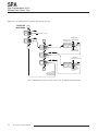
Figure 20. Connections for the HLPRG SPA
–
VOLTAGE
SOURCE +
+ 2-WIRE
CURRENT
– SOURCE
–
4-WIRE
CURRENT +
SOURCE
TOP ROW
TERMINALS
+I/+V –I –V +TX +I
NOTE: DO NOT COUNT
TERMINALS BLOCKED
OFF FROM FACTORY
10 11 12 13 14 15
TERMINALS FOR 3PRG AND 4PRG UNITS
OR UNITS WITH DPDT RELAYS
MIDDLE ROW
TERMINALS
BOTTOM ROW
TERMINALS
1 2 3 4 5 6 7 8 9
NOTE: THE HLPRG SPA
DOES NOT PROCESS
MULTIPLE INPUTS
SIMULTANEOUSLY.
Connections
Figure 20 shows HLPRG input connections. Table 1
gives terminal designations.
34
The Interface Solution Experts
GND
AC OR DC
POWER
SUPPLY
SPA
Site-Programmable Volt &
Milliamp Limit Alarm Trips
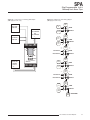
Table 2. Terminals for the SPA
Top Row Terminals
T1
T2
T3
T4
T5
T6
T7
T8
T9
High Level SPA
+I/+V
–I
–V
+TX
(Note 2)
+I
(Note 2)
MR
MR
+Analog
OUT
(Note 1)
–Analog
OUT
(Note 1)
10
11
12
13
14
B7
B8
B9
Middle Row Terminals
1 and 2 Relays
(1PRG and 2PRG)
Not Present
3 Relays (3PRG)
NO3
CM3
NC3
4 Relays (4PRG)
NO3
CM3
NC3
NO2
CM2
NC2
1DPDT Relay
15
Not Present
NO4
CM4
NC4
Not Present
Relay 1(above)
2 DPDT Relays
Bottom Row Terminals
NO2
CM2
NC2
NO2
Relay 1(above)
CM2
NC2
Relay 2(above)
B1
B2
B3
1 Relay (1PRG)
NO
CM
NC
NA
NA
NA
2 Relays (2PRG)
NO1
CM1
NC1
NO2
CM2
NC2
3 Relays (3PRG)
NO1
CM1
NC1
NO2
CM2
NC2
4 Relays (4PRG)
NO1
CM1
NC1
NO1
CM1
NC1
1DPDT Relay
NO2
CM1
Relay 1(above)
B5
CM2
B6
POWER POWER
AC or DC AC or DC
GND
NC2
Not Present
Relay 1(above)
NO1
2 DPDT Relays
B4
NC1
NO1
CM1
NC1
Relay 2(above)
NOTES:
1. When AO option is installed.
2. Use when the SPA is to provide power for 2-wire, loop-powered input devices.
3. When determining the terminal designations, terminals blocked off from the factory should not be counted.
The Interface Solution Experts
35
SPA
Site-Programmable Volt &
Milliamp Limit Alarm Trips
Operation
Once connected to sensors, annunciators (or other
discrete devices), and appropriate power, the SPA
begins to function according to its internal switch
settings and the configuration stored in its nonvolatile internal memory.
Configuration data, stored in memory, is monitored
continuously. Changes can be made at any time.
Any changes made to operating parameters
controlled by choices made in the SPA menu system
take effect immediately.
The settings of the internal DIP switches and
security jumper may also be changed at any time.
Changes to the security jumper setting, however, do
not take effect until unit power is cycled off and on.
The settings for failsafe/non-failsafe and source/sink
(see Figures 3 and 4, respectively), once made, take
effect right away.
LEDs
There are at least three, and as many as six LEDs
on the front panel of the SPA. Each is labeled, and
provides a quick reference for input condition during
normal unit operations.
• READY This LED shows green during normal
operation. Green indicates that the SPA has run its
startup diagnostic and that all internal circuitry is
functioning properly.
The LED goes out if internal errors occur.
• INPUT This LED shows green during normal
operation. Green indicates that an input sensor or
sensors has/have been connected, and that they
are functioning properly.
• TRIP # These LEDs, one per installed relay, show
green when the connected input is in a non-alarm
condition relative to the trip point setting. A red
LED indicates alarm.
36
The Interface Solution Experts
NOTE:
The state of the SPA relays in alarm or nonalarm is determined by the failsafe/non-failsafe
setting of the unit’s internal DIP switches (see
Figure 3, earlier in this manual). Do not
confuse the state of the LED with the state of
its associated relay.
Failsafe relays are ON (energized) when input
is in a non-alarm condition (green LED), OFF
(de-energized) in alarm (red LED).
Non-failsafe relays are ON (energized) when
input is in an alarm condition (red LED), OFF
(de-energized) in non-alarm (green LED).
This design scheme means that the LEDs
associated with relays will always show red when the
corresponding input is in an alarm condition, green in
non-alarm.
Manual Reset
There are two connections labeled “MR” on the SPA
top terminal block. These terminals work in
conjunction with the latching/non-latching alarm
function.
When an SPA is configured with latching alarms
(refer to the description of the “CONF ALRM” menu,
earlier in this manual), an alarm condition will not
“clear”, that is, the relay will not change state, until
the input returns to a non-alarm state AND these
manual reset terminals are shorted and then opened.
Shorting and then opening the MR terminals “clears”
all alarms.
SPA
Site-Programmable Volt &
Milliamp Limit Alarm Trips
Error Codes
Customer Service
Every SPA is subjected to an exhaustive battery of
operational checks and tests prior to its shipment.
Occasionally, however, units can sustain damage
getting from the factory to the user.
If service assistance is ever required for one of the
SPAs in your application, refer to the inside of the
back cover of this manual for the telephone numbers
to Moore Industries STAR Center customer service
department.
As a safeguard, the unit is equipped with a full set of
internal diagnostics that check operation and configuration on power-up. If there are problems with the
microprocessor, or with conflicting operating
parameter settings, the LCD will show an error code
upon unit start-up.
If possible, make a note of the model number of the
offending unit before calling. For fastest assistance,
try to gather information on the unit(s) serial number
and the job and purchase order number under which
it was shipped.
Table 2 lists the error codes.
For most of these problems, it will be necessary to
return the offending SPA to the factory.
Table 2. SPA LCD Error Codes
Error Message
EE FLT
RAM ERR
ROM ERR
What it Means
What to Do
EEPROM Error - The internal processor failed
RAM(memory) Error - The internal processor failed Cycle power to the unit, and if the error occurs
again, return the unit to the factory for service.
CAL ERR
Calibration Error - The factory-set calibration of the
unit has failed to initialize.
DATA ERR
Data Error - There are conflicts in the settings
entered into unit memory. This can be caused by
power loss or fluctuation during power-up.
Cycle power to the unit, then run through the
configuration menus to ensure that the
technician made the correct sensor selections
for the range settings, etc.
PACT ERR
Memory Packet Failure - Internal memory failure
Cycle power to the unit, and if the error occurs
again, return the unit to the factory for service.
CONF ERR
Data Error - There are conflicts in the settings
entered into unit memory. This can be caused by
power loss or fluctuation during power-up.
RJC OPEN
Reference Junction Compensation Resistor
Burnout.
Cycle power to the unit, then run through the
configuration menus to ensure that the
technician made the correct sensor selections
for the range settings, etc.
Cycle power to the unit, and if the error occurs
again, return the unit to the factory for service.
TABL ERR
Internal Table Error - The linearization curve
programming is not correct.
Make sure that the endpoints of the programmed
curve are within the selected INPUT SCALING.
The Interface Solution Experts
37
Declaration of Conformity
EMC Directive 89/336/EEC
Manufacturer’s Name:
Manufacturer’s Address:
Moore Industries-International, Inc.
16650 Schoenborn Street
North Hills, CA 91343-6196
USA
Declares that the product(s):
Product Name:
SPA-CE
MODEL
Model Number(s):
SPA
SPA
SPA
/
INPUT
*
*
*
/
OUTPUT
/
*
*
*
POWER
117VAC
230VAC
**24VDC
/
OPTIONS
/ HOUSING
- CE 1
- CE 1
- CE 1
*
*
*
*Indicates any input, output, option and housing as stated on the product data sheet.
** Indicates any power between 22VDC and 50VDC.
Conforms to the following EMC specifications:
EN50081-1, 1992, Generic Emissions Standard, Residential, Commercial and Light Industry.
EN50082-1, 1992, Generic Immunity Standard, Residential, Commercial and Light Industry.
EN61010-1, 1995, Safety requirements for electrical equipment for measurement and control use.
Supplemental Information:
1
CE option is required.
March 21, 2001
Date
______________________________
_____________________________________
Fred Adt
Quality Assurance Director
Robert Stockham
Moore Industries-International, Inc.
European Contact: Your Local Moore Industries Sales and Service Office
RETURN PROCEDURES
To return equipment to Moore Industries for repair, follow these four steps:
1. Call Moore Industries and request a Returned Material Authorization (RMA) number.
Warranty Repair –
If you are unsure if your unit is still under warranty, we can use the unit’s serial number
to verify the warranty status for you over the phone. Be sure to include the RMA
number on all documentation.
Non-Warranty Repair –
If your unit is out of warranty, be prepared to give us a Purchase Order number when
you call. In most cases, we will be able to quote you the repair costs at that time.
The repair price you are quoted will be a “Not To Exceed” price, which means that the
actual repair costs may be less than the quote. Be sure to include the RMA number on
all documentation.
2. Provide us with the following documentation:
a) A note listing the symptoms that indicate the unit needs repair
b) Complete shipping information for return of the equipment after repair
c) The name and phone number of the person to contact if questions arise at the factory
3. Use sufficient packing material and carefully pack the equipment in a sturdy shipping
container.
4. Ship the equipment to the Moore Industries location nearest you.
The returned equipment will be inspected and tested at the factory. A Moore Industries
representative will contact the person designated on your documentation if more information is
needed. The repaired equipment, or its replacement, will be returned to you in accordance with
the shipping instructions furnished in your documentation.
WARRANTY DISCLAIMER
THE COMPANY MAKES NO EXPRESS, IMPLIED OR STATUTORY WARRANTIES (INCLUDING ANY WARRANTY OF MERCHANTABILITY OR OF FITNESS
FOR A PARTICULAR PURPOSE) WITH RESPECT TO ANY GOODS OR SERVICES SOLD BY THE COMPANY. THE COMPANY DISCLAIMS ALL WARRANTIES ARISING FROM ANY COURSE OF DEALING OR TRADE USAGE, AND
ANY BUYER OF GOODS OR SERVICES FROM THE COMPANY ACKNOWLEDGES THAT THERE ARE NO WARRANTIES IMPLIED BY CUSTOM OR
USAGE IN THE TRADE OF THE BUYER AND OF THE COMPANY, AND THAT
ANY PRIOR DEALINGS OF THE BUYER WITH THE COMPANY DO NOT IMPLY THAT THE COMPANY WARRANTS THE GOODS OR SERVICES IN ANY
WAY.
ANY BUYER OF GOODS OR SERVICES FROM THE COMPANY AGREES
WITH THE COMPANY THAT THE SOLE AND EXCLUSIVE REMEDIES FOR
BREACH OF ANY WARRANTY CONCERNING THE GOODS OR SERVICES
SHALL BE FOR THE COMPANY, AT ITS OPTION, TO REPAIR OR REPLACE
THE GOODS OR SERVICES OR REFUND THE PURCHASE PRICE. THE
COMPANY SHALL IN NO EVENT BE LIABLE FOR ANY CONSEQUENTIAL OR
INCIDENTAL DAMAGES EVEN IF THE COMPANY FAILS IN ANY ATTEMPT
TO REMEDY DEFECTS IN THE GOODS OR SERVICES , BUT IN SUCH CASE
THE BUYER SHALL BE ENTITLED TO NO MORE THAN A REFUND OF ALL
MONIES PAID TO THE COMPANY BY THE BUYER FOR PURCHASE OF THE
GOODS OR SERVICES.
ANY CAUSE OF ACTION FOR BREACH OF ANY WARRANTY BY THE
COMPANY SHALL BE BARRED UNLESS THE COMPANY RECEIVES
FROM THE BUYER A WRITTEN NOTICE OF THE ALLEGED DEFECT OR
BREACH WITHIN TEN DAYS FROM THE EARLIEST DATE ON WHICH THE
BUYER COULD REASONABLY HAVE DISCOVERED THE ALLEGED DEFECT OR BREACH, AND NO ACTION FOR THE BREACH OF ANY WARRANTY SHALL BE COMMENCED BY THE BUYER ANY LATER THAN
TWELVE MONTHS FROM THE EARLIEST DATE ON WHICH THE BUYER
COULD REASONABLY HAVE DISCOVERED THE ALLEGED DEFECT OR
BREACH.
RETURN POLICY
For a period of thirty-six (36) months from the date of shipment, and under
normal conditions of use and service, Moore Industries ("The Company") will
at its option replace, repair or refund the purchase price for any of its manufactured products found, upon return to the Company (transportation charges
prepaid and otherwise in accordance with the return procedures established
by The Company), to be defective in material or workmanship. This policy
extends to the original Buyer only and not to Buyer's customers or the users
of Buyer's products, unless Buyer is an engineering contractor in which case
the policy shall extend to Buyer's immediate customer only. This policy shall
not apply if the product has been subject to alteration, misuse, accident, neglect or improper application, installation, or operation. THE COMPANY
SHALL IN NO EVENT BE LIABLE FOR ANY INCIDENTAL OR CONSEQUENTIAL DAMAGES.
United States • [email protected]
Tel: (818) 894-7111 • FAX: (818) 891-2816
Australia • [email protected]
Tel: (02) 8536-7200 • FAX: (02) 9525-7296
© 2006 Moore Industries-International, Inc.
Belgium • [email protected]
Tel: 03/448.10.18 • FAX: 03/440.17.97
The Netherlands • [email protected]
Tel: (0)344-617971 • FAX: (0)344-615920
China • [email protected]
Tel: 86-21-62491499 • FAX: 86-21-62490635
United Kingdom • [email protected]
Tel: 01293 514488 • FAX: 01293 536852
Specifications and Information subject to change without notice.
User’s Manual Supplement
SPA (HLPRG) and SPA HART
Transmitter Excitation (TX) Power Supply
January 2006
The information contained within this document affects
the following user’s manuals: SPA (HLPRG) 224-715-00,
Revision B and SPA HART, 224-741-00, Revision D.
This supplement has been issued to provide Transmitter
Excitation (TX) Power Supply information and specifications which were not included in the SPA (HLPRG) and
SPA HART User’s Manuals.
Power Supply:
U (Universal): 22-300Vdc or 90-260Vac
CE Unit: 117Vac or 230Vac, ±10%, 47-63Hz.
The CE version is built to order. A change in the
voltage requires a change in fuse value.
Power Consumption:
U (Universal): 2 to 3W, nominal, including use of TX
CE Unit: 2.5 to 4W, nominal, including use of TX
TX Power Output:
Transmitter excitation power of 24Vdc, ±10%@24mA
is provided at the terminals marked TX.
United States • [email protected]
Tel: (818) 894-7111 • FAX: (818) 891-2816
Australia • [email protected]
Tel: (02) 8536-7200 • FAX: (02) 9525-7296
© 2006 Moore Industries-International, Inc.
224-715-02A
Belgium • [email protected]
Tel: 03/448.10.18 • FAX: 03/440.17.97
The Netherlands • [email protected]
Tel: (0)344-617971 • FAX: (0)344-615920
China • [email protected]
Tel: 86-21-62491499 • FAX: 86-21-62490635
United Kingdom • [email protected]
Tel: 01293 514488 • FAX: 01293 536852
Specifications and information subject to change without notice.