1
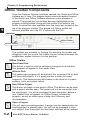
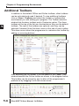
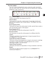
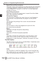
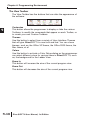
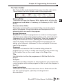
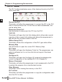
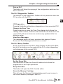
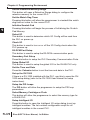
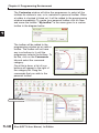
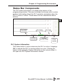
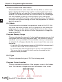
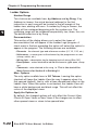
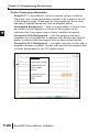
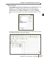
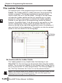
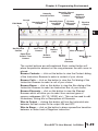
PROGRAMMING
ENVIRONMENT
CHAPTER
4
In This Chapter
Offline Toolbar Components . . . . . . . . . . . . . . . . . . . . .4-2
Online Toolbar Components . . . . . . . . . . . . . . . . . . . . .4-5
Additional Toolbars . . . . . . . . . . . . . . . . . . . . . . . . . . . .4-6
The Options Dialog . . . . . . . . . . . . . . . . . . . . . . . . . . .4-21
Colors in DirectSOFT 6 . . . . . . . . . . . . . . . . . . . . . . .4-24
The Ladder Palette . . . . . . . . . . . . . . . . . . . . . . . . . . .4-28
The Split Screen Feature . . . . . . . . . . . . . . . . . . . . . .4-30
The New Window Feature . . . . . . . . . . . . . . . . . . . . . .4-31
Chapter 4: Programming Environment
Offline Toolbar Components
Once the Program Window has been opened, the Online and Offline
toolbars are in view. The diagram below shows the default location
of the Online and Offline Toolbars whenever a new program is
started. The grayed-out icon buttons become highlighted as the
program is being edited. Along with the toolbar icon buttons, the
button functions are also available from the menu bar located at the
top of the program window. The grayed-out Online toolbar will
become available once the PC is online with the PLC.
1
2
3
4
5
6
7
8
9
1
11
2
13
4
A
B
C
D
Menu bar
Online Toolbar
Offline Toolbar
The toolbars are movable, or floating. By selecting the toolbar and
dragging it with the mouse, the toolbar can be located wherever the
programmer wishes to place it on the desktop.
Offline Toolbar
Read from Disk
This button is used to retrieve and open a program from the disk.
The program will appear in the Ladder View.
Write to Disk
The ladder logic program will be saved to the .prj project file on disk
(not the entire project). It is a good practice to save your work
frequently. This helps prevent data losses in the event of a system
problem, such as a power failure.
New Offline Project
This button will begin a new project offline. This button can be used
with a project already open. The project will not be overwritten with
the new project. You will be prompted to save the project before a
new Ladder View will appear. An Offline Project includes the
program, as well as other types of data, like V-Memory and
documentation.
Open a Project
This will open an existing project. A project can be opened when an
existing project is already open. You will first be prompted to save
your project, then the project that has been selected will be opened.
4-2
DirectSOFT 6 User Manual, 1st Edition
Chapter 4: Programming Environment
Backup to File
Click on this button to make a backup copy of your project.
Edit a Program
This button will turn on the Edit Mode. When the ladder view is in
Edit Mode, the edit cursor will be a solid block on the screen. Click
the Edit Mode button again to toggle back to Display Mode.
Accept the Program
Before the edited program can be downloaded to the PLC, the
Accept button must be pressed. Once this is done, the program will
be compiled; in other words, the program is put into a form that can
be downloaded to the PLC.
1
2
3
4
5
6
Cut
7
This button is available in the Edit Mode. It allows the programmer
to delete a marked, or selected, rung or rungs from the program and 8
place it on the clipboard.
9
Copy
This button allows the programmer to copy one or more marked, or
0
selected, program rungs to the clipboard (see page 5-21).
Paste
1
Whenever rungs are cut or copied, they are stored on a clipboard.
Position the cursor where you want the rungs to go, then use this
2
button to paste the rungs currently on the clipboard to the new
location.
3
Find
4
This button is used to locate an element within a program. The
element can be selected with the cursor before using the button or
A
click on the button and enter the element to be found.
Next
B
Using this button will find the next occurrence of the element
specified when the Find button has been used.
C
Browse for an Element
D
This button provides a quick overview of valid element ranges and
nicknames for the current content as well as a convenient way to
document an element.
DirectSOFT 6 User Manual, 1st Edition
4-3
Chapter 4: Programming Environment
Display the Options Dialog
Using this button will display the Options Dialog which will allow the
programmer to set up the different views available to the
programmer.
1
Zoom
This selection is used to either increase or decrease the size of the
current program view. Click the arrow to select the desired size from
the drop-down menu.
2
3
4
5
6
7
8
9
1
11
2
13
4
A
B
C
D
DS on the Web
This button will open the DirectSOFT on the web window.
Help
This button will open the Help menu window.
4-4
DirectSOFT 6 User Manual, 1st Edition
Chapter 4: Programming Environment
Online Toolbar Components
The following button icons are available after the PLC is placed
online.
1
Online Toolbar
Read the Program From PLC
This button will read the program from the online PLC.
Write the Program to PLC
This button will write the program to the online PLC.
Program Status
This button will turn on the status display for the current view.
New Data View
Using this button will open a Data View window (see Chapter 10).
Change Value
This button will open the Change Value window to allow the
programmer to change element status, values, etc..
New Trend View
This button will open a Trend View window (see Chapter 10).
PLC Mode
This button opens the Mode window to display the current mode of
the PLC and to allow the Mode of the PLC to be changed. Choices
are Run, Program and Test.
System Information
Use this button to open a window with the version, status and error
information about the PLC.
Syntax
This button will run a Syntax check of the PLC and a Duplicate I/O
check.
DirectSOFT 6 User Manual, 1st Edition
4-5
2
3
4
5
6
7
8
9
0
1
2
3
4
A
B
C
D
1
Chapter 4: Programming Environment
Additional Toolbars
In addition to the default Offline and Online toolbars, other toolbars
can be activated and used if desired. To view additional toolbars
click on View > Toolbars and select the toolbar or toolbars that
would assist you with editing your program. The Toolbar selection
window lists fourteen toolbars and a Customize option. The three
toolbars at the top of the list are checked since they are the default
toolbars. The rest of the toolbars are optional, and they can be
selected if desired. Note the down arrow at the end of each toolbar.
This down arrow allows the programmer to customize the toolbar by
adding or removing buttons.
2
3
4
5
6
7
8
9
1
11
2
13
4
A
B
C
D
Add or Remove
Buttons
After selecting the file toolbar, it will be added to the Ladder View
window beneath the Online toolbar as shown in the diagram below.
This toolbar can be moved to any location of the programmer’s
preference by dragging it with the mouse arrow.
Added Toolbar
4-6
DirectSOFT 6 User Manual, 1st Edition
The File Toolbar
Chapter 4: Programming Environment
The File Toolbar duplicates the more commonly used commands
from the main menu File. Notice that the icon buttons are in groups,
divided by a gray vertical line.
New Online Project
Create a new project that linked to the PLC.
Close Project
This button will close the current project. A message window will
pop-up if the program has not been saved. The program can then
be saved.
Save Project to Disk
This button will save the entire project to disk, and will also create a
new auto-backup version of the project.
Save Project to PLC
Use this button to save the entire project to the PLC.
Save As to Disk
Use this button to save the active project to a different disk file.
Import
This button will allow the programmer to import a project from a
non-DirectSOFT 6 format.
Import Element Documentation
This button allows the programmer to import a document containing
nicknames, wiring information and descriptions from comma
separated variable (.csv) text format.
Import Rung Comments
This button will allow the importation of rung comments in text form.
Export
This button is used to export a project to a non-DirectSOFT 6
format (see Chapter 6).
DirectSOFT 6 User Manual, 1st Edition
4-7
1
2
3
4
5
6
7
8
9
0
1
2
3
4
A
B
C
D
Chapter 4: Programming Environment
Export Element Documentation
This button allows the programmer to export element documentation
containing nicknames, wiring information and descriptions in the
current DirectSOFT 6 project to a text file in comma separated
variable text format.
1
2
3
4
5
6
7
8
9
1
11
2
13
4
A
B
C
D
Export Rung Comments
This button will allow the programmer to export the active ladder
logic rung comments in text form.
Preview the Program
Use this button to display the current view as it would appear in
printed format. Once previewed, the program can be printed.
Print
This will allow the printing of the current view and selected
documents.
Print All
Use this button to allow the programmer to print all of the
documents that are selected.
Setup
This button will open the printer setup dialog.
Properties
This button will show the project properties.
Exit
This button will allow the programmer to exit the project. If the
project has not been saved, a pop-up window will remind the
programmer to save the project, otherwise, the project will close.
The Edit Toolbar
The Edit Toolbar is only active in the Edit Mode. It duplicates some
of the main menu Edit commands.
Undo
Use this button to undo the changes to the current rung that has
been edited and not yet compiled. The edit cursor must be on the
rung to be restored when the undo button is clicked on.
4-8
DirectSOFT 6 User Manual, 1st Edition
Chapter 4: Programming Environment
Delete
The Delete button will delete the element under the edit cursor. If
there is no element under the cursor to be deleted, a pop-up
message asks if the rung is to be deleted. If multiple rungs are
selected (highlighted), it will delete these rungs (See Chapter 5).
Insert
This button will allow rows and columns to be inserted in a rung.
Merge the Previous Rung
This button will merge the previous rung with the current rung.
Merge the Next Rung
Use this button to merge the next rung with the current rung.
Browse Contact
This button will open the Instruction Browser window ready for a
contact to be selected.
Browse Coil
This button opens the Instruction Browser window ready for the
selection of a coil.
Browse Boxes
Use this button to open the Instruction Browser with the box
instructions available for selection.
The Search Toolbar
The Search Toolbar only contains two command buttons, Replace
and GoTo.
Replace
This button will activate the replace dialog so the programmer can
search for an object in the program, or a range of elements and
replace them.
GoTo
This button activates a Goto dialog so the programmer can enter a
rung number or addresss he wishes to view. Pressing OK will
display the cursor on the desired rung/address.
DirectSOFT 6 User Manual, 1st Edition
4-9
1
2
3
4
5
6
7
8
9
0
1
2
3
4
A
B
C
D
Chapter 4: Programming Environment
The View Toolbar
The View Toolbar has five buttons that can alter the appearance of
the software.
1
2
3
4
5
6
7
8
9
1
11
2
13
4
A
B
C
D
4-10
Customize
This button allows the programmer to display or hide the various
Toolbars, to modify the commands that appear on each Toolbar, or
to create your own Custom Toolbars.
Themes
Use this button to select from a variety of User Interface Themes
that will give DirectSOFT 6 a new look and feel. You can chose
themes, such as, the Office XP theme, the Office 2003 theme, the
Mac theme, et al.
Colors
Use this button to activate a Color Setup dialog so the programmer
can select different colors for various items in DirectSOFT 6, such
as, the background for the Ladder View.
Zoom In
This button will increase the size of the current program view.
Zoom Out
This button will decrease the size of the current program view.
DirectSOFT 6 User Manual, 1st Edition
The Tools Toolbar
Chapter 4: Programming Environment
The Tools toolbar duplicates the Tools menu from the main menu.
These buttons can be a valuable asset to the programmer.
1
2
3
Memory Editor
This button will open the Memory Editor dialog which will allow the 4
programmer to edit data in V-memory (or R-memory in 305 / 305S
PLCs).
5
Documentation Editor
6
This button opens the Documentation Editor view to be used to
define Nicknames, Wiring Information and Descriptions for the
7
elements which are used in the program.
Assign Nicknames
8
DirectSOFT 6 allows the programmer to create an entire program
9
with Nicknames without first assigning them to the actual elements
(addresses) a.k.a. Symbolic Programming. When the program is
0
ready to be written to the PLC, pressing the Nicknames button
opens the Assign Nicknames dialog where the programmer can
1
assign actual elements (addresses) to the unassigned Nicknames
used in the program.
2
Comment
This button activates the Edit Comments dialog where the
3
programmer can create or modify the comment for the current rung
in the Ladder View, or the current stage in the Stage View.
4
Title
A
Use this button to allow the programmer to Edit the title for the
project.
B
Compare
This button provides a window so the programmer can compare the
C
current program with another program on disk or with the program in
the PLC.
D
Insert Instructions
This button is used to insert instructions from a Mnemonic text file
into the current program, optionally including element
documentation.
DirectSOFT 6 User Manual, 1st Edition
4-11
Chapter 4: Programming Environment
The PLC Toolbar
The PLC toolbar duplicates some of the features found on the PLC
menu menu bar.
1
2
3
4
5
6
7
8
9
1
11
2
13
4
A
B
C
D
Connect to PLC
This button will allow the programmer to connect the PC to the PLC
over a communication link. If a link has not been established, one
can be setup here.
Disconnect from PLC
Use this button to disconnect the PC from the PLC.
Link Info
This button will open the Link Info dialog which will provide a quick
overview of the current link's status and allows the programmer to
edit and set the activation state of the link.
Offline Setup (PLC)
This button allows the configuration of the PLC type while offline.
Memory Map
Use this button to open the current PLC Memory Map.
PLC Tools
This button will open the Hardware Tools list. The programmer can
select a software tool to run from this list as long as it has been
installed.
Configure I/O
This button will open the Configure I/O window that displays the
current configuration of the installed PLC I/O (Chapter 5).
Setup a Password
This button will allow the programmer to set a password in the PLC
to protect the program from unauthorized access.
Clear Memory
This button is for clearing the memory in the PLC.
PLC to Disk
This button will allow the programmer to copy the configuration data
from the PLC to disk.
4-12
DirectSOFT 6 User Manual, 1st Edition
Chapter 4: Programming Environment
Disk to PLC
This button will allow the copying of the configuration data from the
disk to the PLC.
The PLC Diagnostics Toolbar
The buttons on the Diagnostics Toolbar will only be active when the
PC is online with the PLC.
I/O Diagnostics
Pressing this button will perform diagnostics on the connected PLC.
Observe the Scan Time
Press this button to open the Scan Time dialog which allows the
viewing of the current, minimum and maximum scan times from the
current PLC. The scan times are continuously updated while the
dialog is visible.
View Error Messages
The messages button will open a window that displays System
Errors and Fault Messages which have occurred.
The PLC Setup Toolbar
Some of the buttons on the PLC Setup Toolbar can be used offline,
but all of the buttons can be used with the PLC online (depending
on the features of the current PLC).
Set the Pause Bits
Use this button to open the Pause Bit editor which allows the
programmer to set output pause bits.
Setup Overrides
This button will open the PLC Override editor.
1
2
3
4
5
6
7
8
9
0
1
2
3
4
A
B
C
D
Name the Memory Cartridge
This will open the Memory Cartridge dialog used to set a name in
the current memory cartridge in the PLC.
DirectSOFT 6 User Manual, 1st Edition
4-13
Chapter 4: Programming Environment
Set the Retentive Memory Range
This button will open a Retentive Range dialog to configure the
retentive memory for the current PLC.
1
2
3
4
5
6
7
8
9
1
11
2
13
4
A
B
C
D
Set the Watch Dog Timer
Pressing this button will allow the programmer to view/edit the watch
dog time-out value for the current PLC.
Initialize Scratch Pad
Pressing this button will begin the process of Initializing the Scratch
Pad Memory.
Select I/O
This button is used to determine which I/O Config will be read from
the PLC on power up.
Check I/O
This button is used to turn on or off the I/O Config check when the
PLC powers up.
D0-DCM Port Setup
This button is used to setup the D0-DCM communication ports.
Secondary Port Setup
Press this button to setup the PLC Secondary Communication Ports.
Setup Global I/O
This button is used to setup the global I/O for the DL405 PLC only.
Set the Time and Date
Press the Calendar button to set the time and date in the PLC.
Set up the DV-1000
If there is a DV-1000 installed with the PLC, use this to open the DV1000 setup dialog (refer to the DV-1000 User Manual for setup
instructions).
Setup the PID Loops
The PID button will allow the programmer to setup the PID loop
parameters.
Select Memory Cartridge or Flash
This button will allow the programmer to select the memory type for
a DL405 PLC.
Setup Intelligent I/O
Press this button to open the Intelligent I/O setup dialog to set up
intelligent modules. The list contains configuration script for all
intelligent modules in the current PLC.
4-14
DirectSOFT 6 User Manual, 1st Edition
The Debug Toolbar
Chapter 4: Programming Environment
The Debug Toolbar extends the use of the Status button located on
the Online toolbar. These buttons will assist in the debugging of your
program.
1
2
3
4
5
Turn Status ON in All Views
The All Status button will turn on the status for all of the open views
6
in the current project.
Turn Status OFF in All Views
7
The No Status button will turn off the status for all of the open views
in the current project.
8
Open Data View
9
This button will allow the programmer to open an existing Data
View.
0
Close Data View
This button will allow the programmer to close the current Data
1
View.
2
Save Data / Save Data As
These buttons will save the current Data View.
3
Open Trend View
This button will allow the programmer to open an existing Trend
4
View.
Close Trend View
A
This button will allow the programmer to close the current Trend
B
View.
Save Trend / Save Trend As
C
These buttons will save the current Trend View.
Test Mode
D
This button will allow the programmer to use the Test Mode
Operations (see page 10-22).
Stack Operations (DL440 only)
Use this button to monitor the DL440 PLC accumulator and data
stack.
DirectSOFT 6 User Manual, 1st Edition
4-15
Chapter 4: Programming Environment
1
2
3
4
5
6
7
8
9
1
11
2
13
4
A
B
C
D
Trap Monitor
This button will open a dialog which allows the programmer to trap
element values at specific addresses rather than after a scan (see
page 10-25).
The Window Toolbar
The Window Toolbar duplicates the window option from the main
menu. This toolbar may be helpful if the window views need to be
changed often.
New Window
This button will open a new View Window of the current Program
View (e.g. Ladder, Stage, Trend, Mnemonic).
Arrange Views Cascaded
The Cascade button will rearrange views in a cascaded fashion.
Tile Views Horizontally
This button will arrange the program views in a tiled, horizontal
fashion.
Tile Views Vertically
This button will arrange the program views in a tiled, vertical fashion.
Arrange Icons
Use this button to arrange the icons for minimized windows at the
bottom of the main window. If there is an open document window at
the bottom of the main window, then some or all of the icons may
not be visible because they will be underneath this document
window.
Default
Pressing this button will restore window and toolbar positions to their
factory default layout settings.
Close All Views
This button will close all current views.
Output Window
This button will display the Output Window.
Clear Output Window
This button will clear all messages in the Output Window.
4-16
DirectSOFT 6 User Manual, 1st Edition
The Help Toolbar
Chapter 4: Programming Environment
The Help Toolbar duplicates the Help menu accessed from the main
menu.
Help Topic Index
Use this button to open the Help window.
PLC/Instruction Matrix
This button will open the PLC vs. Instruction Set Matrix window.
Getting Started
The Start button will open the Help window to provide help to get
started using DirectSOFT 6.
DS On the Web
This button will open the DirectSOFT on the web window.
Tip of Day
This button will open the Tip of the Day window to provide a helpful
tip.
Unlock
This button will convert DirectSOFT100 to full version using
Purchased Product Keycode.
About
This button will display the DirectSOFT 6 about box.
The Custom Toolbar
DirectSOFT 6 has many
toolbars to select, and if you
select too many, you probably
won’t have much room on the
monitor to effectively edit a
program. The customize toolbar
feature may be well suited for
your use. Click on Customize
at the bottom of the Toolbars
menu to open the Customize
toolbar window.
1
2
3
4
5
6
7
8
9
0
1
2
3
4
A
B
C
D
TIP: A quick way to open the Customize Toolbar dialog is to right-click on
any of the Toolbars in view. This will access the Toolbars menu, then select
Customize...
DirectSOFT 6 User Manual, 1st Edition
4-17
Chapter 4: Programming Environment
The Customize window will allow the programmer to select all the
toolbars he wishes to use, or to customize a personal toolbar. When
a toolbar is checked (clicked on) it will be added to the programming
window immediately. To create your personal toolbar click on New
and name the toolbar. “My toolbar” is the name given to a custom
toolbar in the diagram below.
1
2
3
4
5
6
7
8
9
1
11
2
13
4
A
B
C
D
The toolbar will be added to the
programming window as an add-on
toolbar. The toolbar will not have
any icon buttons in it until the
programmer selects the buttons. To
do this, click on the Commands
tab and select the command
category.
Once this is done, a list of icon
buttons will appear to the right of
the category list. Drag the
commands that you wish to the
personal toolbar.
Personal Toolbar
4-18
DirectSOFT 6 User Manual, 1st Edition
Chapter 4: Programming Environment
Status Bar Components
The PLC status information is located at the bottom of the
programming window. This area is divided into boxes which contain
pertinent information about the PLC operation and status when the
PLC is online or offline. These boxes can be classified as status
buttons.
PLC System
Information
PLC Mode
Link
Information
PLC System Information
PLC Type
Program
Memory Usage
Program
Cursor
Location
This status button is active whenever the PLC is online. It displays
OK to indicate the PLC is running without an error. Clicking the
button is like using the System Info button in the online toolbar. It
will open the PLC System Information window.
DirectSOFT 6 User Manual, 1st Edition
1
2
3
4
5
6
7
8
9
0
1
2
3
4
A
B
C
D
4-19
Chapter 4: Programming Environment
Communication/Link Information
This status button is active when the PLC is offline or online. The
button displays the PLC status and the communication link name.
Clicking this button will open the Communication/Link Information
window. The window will show the communication error messages.
It is also possible to edit the communication link if it becomes
neccesary. If the PLC is offline, it will indicate that here. Clicking on
the button with offline showing will allow the programmer to connect
the PLC to the PC.
1
2
3
4
5
6
7
8
9
1
11
2
13
4
A
B
C
D
PLC Mode
This status button indicates the operational mode of the PLC. Not
only does this button indicate the PLC Mode but it also allows the
programmer to use this button like the Mode button in the online
toolbar. Clicking on this button will allow the person to change the
mode of the PLC.
Program Memory Usage
This box indicates the amount of relay ladder program memory that
is available and how much has been used. The format is: memory
used/total memory available. If the available memory is exceeded,
an asterisk (*) will appear beside the amount used. Here are some
examples:
• For a DL06 CPU with program memory of 00003/07680 indicates that 3
words have been used out of a total of 07680.
• For a DL230 CPU indicating the program memory with *00725/00512.
This means that the amount of words used has exceeded the total
program memory available.
PLC Type
This box indicates the type of PLC that is being used.
Program Cursor Location
4-20
This box indicates the position of the program cursor in the Ladder
View. This indicator changes with each movement of the cursor.
DirectSOFT 6 User Manual, 1st Edition
Chapter 4: Programming Environment
The Options Dialog
Before continuing to edit your program, it is a good idea to get
familiar with the DirectSOFT 6 Options Dialog. This dialog actually
has seven dialogs within which are used to setup the appearance of
each of the views available. To open the dialog, either click on the
Options button or on View > Options. Each view dialog is indicated
by a tab labeled:
• Data View - used to monitor and debug the program
• Global - this affects all views (display of aliases or nicknames)
• Ladder - options for the ladder view
• Stage - options used for the stage view
• Trend - options used for data trending
• XRef - used to setup the cross reference view (display mode,
documentation, etc.)
• XRef DB - definitions for cross reference database queries
Only the Global and Ladder options will be discussed in this
chapter. The other option tabs will be discussed in later chapters
after adequate coverage of some of the more advanced features of
DirectSOFT 6.
DirectSOFT 6 User Manual, 1st Edition
1
2
3
4
5
6
7
8
9
0
1
2
3
4
A
B
C
D
4-21
Chapter 4: Programming Environment
Ladder Options
1
2
3
4
5
6
7
8
9
1
11
2
13
4
A
B
C
D
4-22
Number Rungs
Two choices are available here, by Address and by Rung. If by
Address is chosen, the actual decimal address for the first
instruction in each rung will be located in the left margin of the
ladder view, starting with zero. If number by Rung is chosen, the
rungs will be numbered beginning with the number one. The
remaining rungs will be numbered sequentially, two, three, four, etc.
The default selection is by Rung.
Documentation
This section of the dialog allows you to select the types of
documentation that will appear in the Ladder Logic program. A
check mark in the box preceding the option will select the option to
appear in the program. The following choices are available:
• Elements - the element type and reference number (X1, Y3, C10, etc.)
• Nicknames - a name given to the element by the programmer or user
(clamp, switch, etc.)
• Wiring Info - a descriptive tag for keeping track of wiring (Blue 027)
• Descriptions - notes attached to individual elements (gate open, clamp
up)
• Comments - note attached to the rung, i.e. This is the start of the
Wash Process for Section 9 in Building 10
Misc. Options
The only option availble here is 3-D Tokens. Leaving this option
checked will leave the Ladder View the way it appears when it is
first opened (default), that is, with a three dimensional effect on the
Ladder View. When this option is unchecked, the Ladder View will
have a white background and black rungs. This will not affect the
colors of the displayed views.
Apply the Options to:
By default, the changed options will only affect the Current View.
Check All Open Views or New Views if the changes are to affect
other opened views or views to be opened later.
DirectSOFT 6 User Manual, 1st Edition
Global Options
Chapter 4: Programming Environment
The options available with the Global tab affect the current and all
new projects that are opened during any session.
Selecting the Global Options
• Default View - the view that is highlighted in the Default View window
when the OK button is selected will be the default view that appears
whenever a project is opened.
• Display Aliases - Aliases are alternate names given to certain elements
or addresses. For example, TA0 is an alias for a timer accumulator data
starting at V0. It is much more meaningful to use the aliases rather than
the counterpart memory address notations. But in the end, it is a matter
of preference. The aliases can be turned ON or OFF globally. See the
PLC User Manual for a complete list of aliases for the CPU being used.
• Display Nicknames - when this is selected, all current or future projects
opened will display the nicknames. Selecting Display Nicknames here
will have precedence over how this option is set for the individual views
in the other options.
• Display Toolbar Text - this option allows the user to hide or display the
text for each button in the Toolbars. When the text is hidden, the buttons
reduce in size.
• Default Docking Position - this option allows the user to choose the
position relative to the Ladder View that any Views opened (Data View,
XRef View, etc.) will reside in.
DirectSOFT 6 User Manual, 1st Edition
1
2
3
4
5
6
7
8
9
0
1
2
3
4
A
B
C
D
4-23
Chapter 4: Programming Environment
Colors in DirectSOFT 6
1
2
3
4
5
6
7
8
9
1
11
2
13
4
A
B
C
D
Colors are used in DirectSOFT 6 for personal appearance and for
certain information. This will be a discussion of how and where
colors are used.
Select New Colors
4-24
The programmer can setup the colors that he prefers for the
projects to be developed. The selected colors will remain the same
for each project. To open the Color Setup window, click on View >
Color Setup or click on the Color button in the View toolbar button
group. The Color Setup will appear like the dialog below.
Click on item
to select for a
color change
Click on the
desired color
Letters match
documentation
selections
Vertical bars
match
highlighting for
selected rungs,
uncompiled, etc.
The colors are changed by first selecting the usage (Normal
Background, Comment, etc.) under the Selection section then
clicking on the color in the Colors palette (drop-down menu). The
Sample area (below the Color palette) has a color bar that will
change as the colors are selected. Rows of text will also change
color for each type of documentation selected. These are the rows
of Cs, Ds, Ws, etc.
DirectSOFT 6 User Manual, 1st Edition
Color Selections
Chapter 4: Programming Environment
Normal Background 앥 the normal background color (the default is
white with 3-D Token disabled)
Uncompiled Background 앥 color for items which are modified and
uncompiled
Unsaved to Disk Background 앥 color for items which are modified
and unsaved to disk
Unsaved to PLC Background 앥 color for items which are modified
and unsaved to the PLC
Disabled Background 앥 color for views which are disabled
Selected Background 앥 used for setting the color that appears
when something in the program is selected. For example, if a range
of rungs is selected (to copy, delete, etc.) the selection is highlighted
with a color (default is blue)
Status Background 앥 when online status is selected, this
background color shows that the element is enabled (default is
aqua)
Status Foreground 앥 the color the individual element addresses
show when they are active during status
Comments 앥 the color used for the rung comments
Description 앥 the color used for the element description
Wiring Information 앥 the color used to indicate the wiring
information
Nickname 앥 the color used to indicate the nicknames
Element 앥 the color used for the element address (X10, IO000,
etc.)
Token 앥 the color used for the ladder program
Block Cursor 앥 the color of the cursor box in Ladder View
Box Background 앥 the color within each instruction box.
The Default Settings
If the colors become totally disorganized, click on the Defaults
button to restore the colors to the DirectSOFT 6 default settings.
1
2
3
4
5
6
7
8
9
0
1
2
3
4
A
B
C
D
Monochrome
Selecting the Monochrome button will set all colors to black with a
white background.
DirectSOFT 6 User Manual, 1st Edition
4-25
Chapter 4: Programming Environment
Colors Conveying Information
1
2
3
4
5
6
7
8
9
1
11
2
13
4
A
B
C
D
4-26
DirectSOFT 6 uses different colors to indicate certain conditions.
There are color coded vertical bars located in the margin to the left
of the program rungs. These bars let the programmer know what
has been compiled and saved. See the diagram below.
Uncompiled Background 앥 when a rung is edited, a vertical color
bar (default yellow) appears to the left of the program as an
indication that the program has not been compiled (accepted).
Unsaved to Disk Background 앥 after the program has been
compiled, the uncompiled bar is replaced with another bar (default
green) to indicate that the program has not been saved the disk.
Unsaved to PLC Background 앥 one other color bar is used after a
program has been compiled, this bar indicates that the program has
not been downloaded to the PLC (default blue).
Color Bars
Uncompiled (Yellow)
Compiled, but not
written to disk
(Green)
Compiled, but not
written to PLC
(Blue)
DirectSOFT 6 User Manual, 1st Edition
Select a Theme
Chapter 4: Programming Environment
The Themes dialog allows the programmer to select the look of the
DirectSOFT 6 programming window, much like selecting the
appearance for a computer using Windows. To open the dialog
window either click on View > Themes or click on the Themes
button in the View toolbar button group. The default theme is Office
XP.
The theme selected for the window below is the Beveled look. Note
the darkened outlines of the menu buttons.
DirectSOFT 6 User Manual, 1st Edition
1
2
3
4
5
6
7
8
9
0
1
2
3
4
A
B
C
D
4-27
Chapter 4: Programming Environment
The Ladder Palette
1
2
3
4
5
6
7
8
9
1
11
2
13
4
A
B
C
D
An important part of the programming environment is the Ladder
Palette. The Ladder palette is visible whenever the programming
window is opened. The element symbols are grayed-out and
inactive when the not in the Edit Mode. Turning on the Edit Mode
activates the Ladder palette and the tool symbols are no longer
grayed-out. When a new project is started, the Ladder palette is
located on the right side of the programming window by default,
however, the palette floats. It can be moved to any position on the
monitor viewing area. Simply “grab” the palette with the mouse
arrow on the bar at the top of the palette and move it to wherever it
may work best for the programmer. The palette can also be resized
similar to the one shown on the facing page.
Ladder Palette
Be Familiar with the Ladder Palette
The Ladder palette is very helpful when first learning to use
DirectSOFT 6. The hot keys can be learned while using the Ladder
palette. The hot keys are labeled on the element keys. Using the hot
keys may be quicker for many programmers. The hot keys appear in
the “Tool Tip” whenever the cursor is over the element button.
NOTE: The Ladder palette which appears on your computer screen may be
different than what is shown in this manual. The tools that appear are
dependent upon the type of CPU being used.
4-28
DirectSOFT 6 User Manual, 1st Edition
Chapter 4: Programming Environment
Edit Mode
Accept
Not Equal to
Contact
Equal to/or
Greater Than
Contact
Normally Closed
Immediate
Negative
Contact
Differential
Contact
Normally Open
Positive
Equal to
Immediate
Differential
Contact
Contact
Contact
Normally
Closed Contact
Normally Open
Contact
Less Than
Contact
Browse
Coils
Browse
Contacts
Browse
Boxes
Wire to Output
Browse
Elements
Wrap Wire to
Stage
The contact buttons are self-explained. Each contact button will
place the particular element on the rung wherever the edit cursor is
placed.
Browse Contacts 앥 click on this button to view the Contact dialog
of the Instruction Browser to select a contact of your choice.
Browse Coils 앥 click on this button to view the Coil dialog of the
Instruction Browser to select a coil of your choice.
Browse Boxes 앥 click on this button to view the Box dialog of the
Instruction Browser to select an Instruction Box of your choice.
Browse Elements 앥 click on this button to view the Element
Browser which will allow you to select from various types of
memory addresses (X0, Y0, V2000, etc.). This can be used to edit
Nicknames, Wiring info or Descriptions of Elements.
Wire to Output 앥 clicking this button will turn the horizontal wire
between the last contact to the output ON and OFF.
Wire to Stage 앥 click on this button to draw a powerflow transition
between a contact and a Stage box instruction.
DirectSOFT 6 User Manual, 1st Edition
1
2
3
4
5
6
7
8
9
0
1
2
3
4
A
B
C
D
4-29
Chapter 4: Programming Environment
The Split Screen Feature
1
2
3
4
5
6
7
8
9
1
11
2
13
4
A
B
C
D
There may be times when more than one part of the same program
needs to be viewed. DirectSOFT 6 has a split screen feature that
allows the programmer to split the program, horizontally, into two
panes.
Split Screen Bar
4-30
To use the split screen feature, there is a bar, Split Screen bar,
located in the right-hand corner of the Ladder View. To split the
screen, position the cursor over the Split Screen bar, then press and
hold the left mouse button. When a parallel bar appears, move it
down to bring the split screen into view and size the screen to your
convenience.
Split Screen Bar
This diagram
illustrates the split
screen. Notice
that the lower
pane is showing a
different rung
than the upper
pane.
Different
parts of the
program can
be viewed
DirectSOFT 6 User Manual, 1st Edition
Chapter 4: Programming Environment
The New Window Feature
Another handy feature of DirectSOFT 6 is the New Window feature.
This feature is used to open two or more Ladder Views of the same
program. Having two or more views open at once can be helpful
when programming a lengthy program or to view two different parts
of a program simultaneously. To open a new window, click on
Window > New Window. You will know that there are two windows
open by observing the two Ladder View tabs. To place the two
views side by side, click on Window > Tile Vertically. The two
views will be displayed like shown in the diagram below.
1
2
3
4
5
6
7
8
9
0
1
2
3
4
A
If the Window toolbar group is shown on the programming window,
B
simply click on the New Window button then the Tile Vert. button. If
desired, the two views can also be arranged tiled horizontally.
C
Notice that the split screen feature has been used in the diagram.
Ladder View 1 has the split screen.
D
Split Screen
DirectSOFT 6 User Manual, 1st Edition
4-31
Chapter 4: Programming Environment
Notes:
1
2
3
4
5
6
7
8
9
1
11
2
13
4
A
B
C
D
4-32
DirectSOFT 6 User Manual, 1st Edition