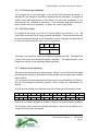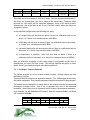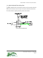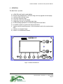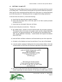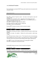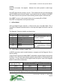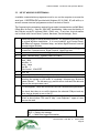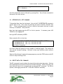
1
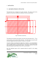
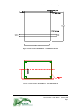
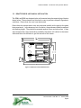
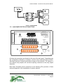
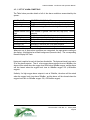
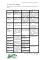
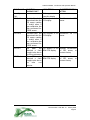
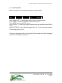
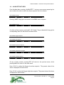
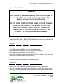
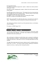
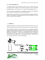
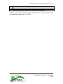
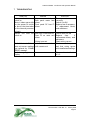
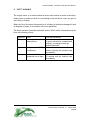
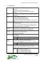
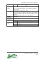
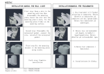
ANALOX SUB Mk II F – Hyperbaric Oxygen and
Carbon Dioxide Monitor
With Automatic Pressure Compensation
Installation and Operation Manual
`
Analox Sensor Technology Ltd
15 Ellerbeck Court, Stokesley Business Park
North Yorkshire, TS9 5PT
T: +44 (0)1642 711400
F: +44 (0)1642 713900
W: www.analox.net
E: [email protected]
ANALOX SUB MKII – Installation and Operation Manual
LIST OF CONTENTS
1
PACKAGING CONTENTS CHECK .......................................................................... 3
2
INTRODUCTION............................................................................................. 4
3
INSTALLATION.............................................................................................. 6
3.1
3.2
3.3
4
OPERATION ................................................................................................ 15
4.1
4.2
4.3
4.4
4.5
4.6
4.7
4.8
4.9
4.10
5
SWITCHING ON AND OFF ........................................................................... 16
MAIN DISPLAY SCREEN .............................................................................. 17
ALARM SYSTEM....................................................................................... 18
OXYGEN INJECTION SYSTEM........................................................................ 23
FUNCTION KEYS...................................................................................... 25
ALARM SETPOINT MENU............................................................................. 26
CALIBRATION MENU ................................................................................. 29
INTERFACE CALIBRATION MENU ................................................................... 36
SETUP MENU......................................................................................... 38
OXYGEN INJECTION MENU .......................................................................... 39
DATALOGGING............................................................................................. 40
5.1
5.2
5.3
5.4
5.5
6
MAIN PANEL MECHANICAL INSTALLATION...........................................................6
REMOTE SENSOR MECHANICAL INSTALLATION.....................................................8
SYSTEM ELECTRICAL INSTALLATION .................................................................9
RS232 DATA LOGGING CONNECTION .............................................................. 40
USE OF WINDOWS HYPERTERMINAL ............................................................... 42
RETRIEVE DATA: GET COMMAND................................................................... 43
DELETE DATA: DEL COMMAND...................................................................... 43
USE OF RETRIEVED DATA ........................................................................... 44
CALIBRATION .............................................................................................. 44
6.1
6.2
6.3
6.4
6.5
6.6
6.7
SEMI AUTOMATIC GAS CALIBRATION .............................................................. 45
PRESSURE SENSOR CALIBRATION .................................................................. 46
OXYGEN SENSOR CALIBRATION .................................................................... 46
CARBON DIOXIDE SENSOR CALIBRATION .......................................................... 47
TEMPERATURE SENSOR CALIBRATION ............................................................. 47
HUMIDITY SENSOR CALIBRATION................................................................... 49
INTERNAL CALIBRATION ............................................................................ 50
7
TROUBLESHOOTING ...................................................................................... 57
8
SAFETY WARNINGS ....................................................................................... 58
9
SPECIFICATION ............................................................................................ 59
10
DISPOSAL .................................................................................................. 49
Document Ref: AS2F-801-14 - January 2009
Page 2
ANALOX SUB MKII – Installation and Operation Manual
1
PACKAGING CONTENTS CHECK
a) Analox Sub Mk II F main unit.
b) Analox Sub Mk II F REM1 Oxygen, Carbon Dioxide and Depth Remote Sensor Unit
c) Optional Analox Sub Mk II REM2 Temperature and Humidity Remote Sensor Unit
d) Optional Analox Sub Mk II REM3 Oxygen Injection Controller Unit with control
cable
e) Optional Mains Cable (AC powered instruments only)
f) Connecting cables to connect Main Unit to REM1 and optional REM2/REM3 units
g) Calibration adaptors and tubing
h) Optional Datalogging cable
i) User Manual
j) Test Certificate
Please refer to the Safety Warning information in Section 8
and to the Caution notice in Section 3.3.
Document Ref: AS2F-801-14 - January 2009
Page 3
ANALOX SUB MKII – Installation and Operation Manual
2
INTRODUCTION
The Analox Sub Mk II F is a combined oxygen, carbon dioxide (CO2) and pressure
monitor that automatically compensates the CO2 data for pressure effects.
Optionally, temperature and humidity may also be measured if fitted at the time of
manufacture. An optional controller module may also be added to provide oxygen
injection to maintain oxygen levels at preset levels.
Parameter
Sensing technology
Oxygen
Carbon Dioxide
Pressure
Temperature
Humidity
Oxygen (Control Sensor)
Electrochemical cell
Infra-red absorption
Strain gauge
Platinum Resistor
Capacitive
Electrochemical cell
Sensor
Location
REM1
REM1
REM1
REM2
REM2
REM3
The complete system consists of:
a) The SUB Mk II F main unit intended for installation in control rooms (special
versions are available if it is required to mount the Main Unit in the hyperbaric
environment).
b) The REM1 and optional REM2 and/or REM3 intended for installation in
hyperbaric environments.
A large graphic display on the main unit shows the value of each measured parameter
and the remote unit provides local displays of the monitored parameters.
The main panel can provide audio and visual alarms for the measured gas parameters.
The alarm setpoints may be easily adjusted using the pushbuttons on the main panel.
The overall system is powered by a single supply as indicated on the rear of the main
unit. The remote unit connects to the main panel, from which it obtains power.
The sensors are housed in splashproof enclosures that are vented to prevent collapse
in hyperbaric environments. Gas levels are monitored by diffusion across waterproof
membranes built into the REM1 (and REM3 when fitted) unit.
The user should ensure that the gas inlet ports remain as clean as possible to prevent
the waterproof membranes becoming blocked. The sensor enclosure vents, situated
Document Ref: AS2F-801-14 - January 2009
Page 4
ANALOX SUB MKII – Installation and Operation Manual
beside the electrical connections must also be kept clean.
Document Ref: AS2F-801-14 - January 2009
Page 5
ANALOX SUB MKII – Installation and Operation Manual
3
INSTALLATION
3.1 MAIN PANEL MECHANICAL INSTALLATION
The Main Panel unit is designed to be panel mounted. The panel must first be
prepared to accept the instrument by making the cutout as shown below.
Figure 1: Main Panel - Panel Cutout
The shaded area represents the aperture into which the main panel will fit. The 4
mounting holes are to be drilled 10mm diameter. Four M5 captive nuts and four M5
screws are supplied with the instrument to mount it to the panel.
If the unit is likely to be subjected to high levels of vibration, it is recommended to
construct a supporting bar or shelf towards the rear of the unit. The two figures below
show a suitable means of providing this support. The absolute position of the shelf
should be anywhere within 50mm of the rear of the instrument.
Note that additional space will be required behind the panel for the mating
connectors.
Document Ref: AS2F-801-14 - January 2009
Page 6
ANALOX SUB MKII – Installation and Operation Manual
Figure 2:MAIN PANEL REAR SHELF – VIEW FROM ABOVE
Figure 3: MAIN PANEL REAR SHELF – VIEW FROM REAR
Document Ref: AS2F-801-14 - January 2009
Page 7
ANALOX SUB MKII – Installation and Operation Manual
3.2 REMOTE SENSOR MECHANICAL INSTALLATION
The REM1 and REM2 are designed to be wall mounted using the mounting lugs fitted as
shown below. The enclosures are fitted with a vent to prevent collapse in hyperbaric
conditions. Ensure that the vent is not obstructed
Ensure that the remote sensor units are positioned sensibly with regard to the gases
being monitored. In the absence of air circulation, the gas sensors should be mounted
at breathing height. They should be mounted against a near vertical surface If they
were mounted flat, there would be a possibility that water will collect in the sensor
inlets and block the diffusion of gas into and out of the sensor.
Figure 4: REM MOUNTING DIMENSIONS
Document Ref: AS2F-801-14 - January 2009
Page 8
ANALOX SUB MKII – Installation and Operation Manual
3.3 SYSTEM ELECTRICAL INSTALLATION
Caution
It is advised to ensure that the system is always switched off whenever making or
modifying the electrical connections to the system. Mains powered instruments
should be unplugged from the mains for personal safety. All instruments (AC and
DC powered) should be powered down. There is a possibility of damaging the
system by tampering with live connections.
The Main Panel unit requires an electrical supply. Mains powered versions are
provided with a mains cable. DC powered versions have rear panel terminals to accept
a DC supply, and an internal line filter. Terminals are provided on AC powered
versions to also allow them to operate from DC supplies, but there is no internal line
filter fitted.
An Earth terminal is also provided, although mains powered systems can be earthed
through the mains cable. The earth is only used for screening purposes.
A 2 metre connecting lead is supplied which must connect between the Main Panel and
the Remotes Sensors as shown below. The cable is supplied with a break in the middle,
with the wires temporarily connected through a terminal connector. This allows the
user to ‘break’ the cable for wiring through the hull of pressure chambers. If there
are no REM2 or REM3 sensors fitted, the cable connects directly into REM1. Additional
cables supplied connect the REM1, REM2 and REM3 (when fitted) sensors together in a
“daisy-chain” or style.
The cable screen may be required in certain installations to minimise interference
with other systems (voice communications etc). The cable screen is connected to the
earth of the Main Panel, and should be continued through to the remote sensors.
Some special versions of the remote sensors are built into metal enclosures which may
themselves be earthed. In such cases, it may sometimes help to disconnect the screen
connection at the terminal block to avoid the presence of an earth loop.
The cable is a two pair, overall screened, flame retardant (BS4066 and IEC332 Part 3)
cable. Each core is 7 strands of 0.254mm diameter wire (csa 0.35mm2). Overall
cable diameter is nominally 4.2mm.
Document Ref: AS2F-801-14 - January 2009
Page 9
ANALOX SUB MKII – Installation and Operation Manual
Figure 5: SYSTEM WIRING
3.3.1 MAIN PANEL ELECTRICAL CONNECTIONS
SERIAL NO
RS232
DATALOG
PORT
REMOTE
SENSOR
CONNECTION
SUB MKII F
DC POWER INPUT
+24V
0V
+ CH1 1
2
3
4
5
6
ANALOGUE OUTPUTS
+ CH2 - + CH3 - + CH4 7
8
RELAY1
RELAY2
RELAY3
NO COM NC
NO COM NC
NO COM NC
15
Analox Sensor Technology
15 Ellerbeck Court, Stokesley,
TS9 5JY, UK
Tel +44 1642 711400
www.analox.net
16
17
18
19
20
21
22
23
9
10
11
RELAY4
12
+ CH5 13
110/230V AC
INPUT
14
RELAY5 RELAY6
NO COM NC NO COM NO COM
24
25
26
27
28
29
30
FUSE
500mA (T)
EARTH
All electrical connections are situated on the rear of the main panel. Depending upon
the configuration ordered by a customer, not all of the connections may be fitted.
Also there may be no internal connections to some of the terminals. For instance, a
unit without relay outputs will not have anything connected to the relay output
terminals.
Rear Panel Terminals permit connection of the following (The provision of these
terminals depends on the combination of options ordered)
Document Ref: AS2F-801-14 - January 2009
Page 10
ANALOX SUB MKII – Installation and Operation Manual
3.3.1.1 AC Power Input (Optional)
The connector for an AC mains input is only fitted to AC powered instruments. A
standard IEC type connector and cable is supplied with the instrument. A plug will be
fitted to the cable appropriate to the country to which the instrument is first
delivered (UK, US, European or Australian). If an alternative plug type is required,
either contact Analox for assistance, or source the correct type locally.
3.3.1.2 DC Power Input
DC voltage in the range 12v to 24v DC may be applied to terminals 1 to 4. No
connection is necessary for AC mains powered instruments. These terminals may still
be used to temporarily power an AC instrument from DC, although note that there is
no line filter fitted to the DC input in this configuration.
1
2
3
4
DC Power Supply Input
+24V
0V
Terminals 1 and 2 (positive input) are commoned together internally. Terminals 3 and
4 (zero volt input) are commoned together internally. This permits power to be
looped into and out of the equipment where necessary.
3.3.1.3 Relay Outputs (Optional)
The system can provide up to six relay outputs. Relays 1 to 4 provide volt-free single
pole changeover contacts, while Relays 5 and 6 provide volt-free single pole normally
open contacts.
.(if it is essential to have the normally closed contact from either Relay 5 or Relay 6,
this can be arranged by modifying internal wiring -consult the manufacturer for
details) .
All of the connections are provided on terminals 15 through to 30 as shown below:
15
16
17
RELAY1
NO COM NC
18
19
20
RELAY2
NO COM NC
21
22
23
RELAY 3
NO COM NC
24
25
26
RELAY 4
NO COM NC
27
28
RELAY 5
NO COM
29
30
RELAY 6
NO COM
Each relay is internally assigned to an alarm condition, or group of alarm conditions.
The following table shows the standard allocations, which may be altered via a
configuration file within the system.
Document Ref: AS2F-801-14 - January 2009
Page 11
ANALOX SUB MKII – Installation and Operation Manual
SYSTEM
REM 1
REM1+ REM2
RELAY1
Oxygen Low
Oxygen Low
RELAY2
Oxygen Hi
Oxygen Hi
RELAY 3
CO2 Hi
CO2 Hi
RELAY 4
CO2HiHi
CO2HiHi
RELAY 5
Depth Low
Temperature
Lo or Hi
RELAY 6
Depth High
Humidity
Lo or Hi
The relays are set as standard in ‘Fail Safe’ mode. With the instrument switched off,
the relays are de-energised, and this is taken as the alarm state. Therefore when
switched on, the relays will be energised whenever there is NO alarm present.
Alternatively, the relays may be set in non ‘Fail-Safe’ mode, when the relays are
energised in alarm.
In the standard configurations the following will apply
a) an oxygen relay will also show an alarm if there is a calibration fault on the
sensor, or if there is no communications with REM1.
b) a CO2 relay will also show an alarm if there is a calibration fault on the sensor,
or if there is no communications with REM1.
c) a pressure/depth relay will also show an alarm if there is a calibration fault on
the sensor, or if there is no communications with REM1.
d) a temperature or humidity relay will also show an alarm if there is a
calibration fault on the sensor, or if there is no communications with REM2.
Note the allocation of alarms to each relay output is configurable at the time of
manufacture, as is the ‘Fail Safe’ mode. The settings supplied may differ to those
shown above if previously arranged with the manufacturer.
3.3.1.4 Analogue Outputs (Optional)
The system provides up to five 4-20mA output channels. Voltage outputs are also
available by request.
These provide active outputs (as opposed to passive). The 4-20mA signal is sourced by
the Analox equipment. Only passive equipment should be connected to these outputs.
The default factory settings are to assign each of the outputs to each of the measured
parameters as shown below. 4mA is set to represent the zero of the measured
parameter, whilst 20mA is set to represent the full scale of the measured parameter.
As an example, for a 0-2000mBar pO2 channel, 4mA will represent 0mBar, and 20mA
will represent 2000mBar.
5
6
7
CH1
+
OXYGEN
8
CH2
+
10
11
CH3
-
CO2
9
+
DEPTH
12
CH4
+
14
CH5
TEMP
13
+
HUMIDITY
Document Ref: AS2F-801-14 - January 2009
Page 12
ANALOX SUB MKII – Installation and Operation Manual
The internal configuration file allows these settings to be altered if for instance a
customer perhaps wants 4-20mA to represent say 100-500mBar pO2. The internal
configuration also allows for instance if two oxygen outputs were required etc.
Note the allocation of parameters to each channel is the default setting for a system
fitted with REM1 and REM2 sensors. The settings supplied may differ to those shown
above if previously arranged with the manufacturer.
3.3.1.5 RS232 Datalogging Port (Optional)
Please refer to Section 5 for details of this connection.
Document Ref: AS2F-801-14 - January 2009
Page 13
ANALOX SUB MKII – Installation and Operation Manual
3.3.2 REM3 OXYGEN INJECTION INSTALLATION
The REM3 is supplied with a 2m cable which connects a volt-free contact within the
REM3 into the customers control wiring for the injection solenoid as shown below.
For further assistance regarding solenoids, please contact Analox.
Figure 6: INJECTION CONNECTIONS
Document Ref: AS2F-801-14 - January 2009
Page 14
ANALOX SUB MKII – Installation and Operation Manual
4
OPERATION
The Main Panel provides
a)
b)
c)
d)
e)
f)
g)
h)
i)
a 240x128 pixel liquid crystal display
function key pushbuttons F1-F5 which align with key legends on the display
a yellow alarm indicator lamp
a red fault indicator lamp
a contrast control for the display
a brightness control for the display back light
an Acknowledge pushbutton to acknowledge alarms and faults
an audible sounder to annunciate alarms and faults
a power switch controlling power to the instrument and to the remote sensor
units
j) a fuse F1 for the Main Panel
k) a fuse F2 for the Remote Sensors
SUB MK II F
Figure 7: MAIN PANEL DETAIL
Document Ref: AS2F-801-14 - January 2009
Page 15
ANALOX SUB MKII – Installation and Operation Manual
4.1 SWITCHING ON AND OFF
The Main Panel and the Remote Sensors are switched on by operating the Power switch
on the Main panel. The switch has a locking device to prevent inadvertent operation.
Gently pull the lever outwards and then down to turn the power on, and outwards and
up to turn the power off. Releasing the lever re-applies the locking mechanism.
If the unit does not switch on, check the following:
a) check that the external power supply is healthy.
b) check that the supply fuse on the rear panel is not blown (mains powered
instruments only).
c) check that the front panel fuses are not blown.
Several events take place at switch on. These are:
a) the audible alarm sounds for several seconds while the processor initialises.
This ensures that in the event of a system crash via the on-board Watchdog
controller, an operators attention will be attracted by the audible alarm. .
(This can be disabled if necessary – consult Analox and request information
sheet AS2F-046).
b) both the Fault and Alarm indicators are illuminated to prove their operation
c) all pixels on the display are turned on and then off as a test of the display
d) a version number message is displayed on the screen as shown below. Note the
version number on the screen may change as upgrades to the system are made.
ANALOX SENSOR TECHNOLOGY LIMITED
ANALOX SUB MK IIF
ATMOSPHERE MONITORING SYSTEM
*** Version ASF-310-xx ***
dd-mmm-yyyy
Performing pre-startup routines
Please wait while system initialises....
Tel +44 1642 711400 /Fax +44 1642 713900
www.analox.net
e) the screen is then cleared and the main application screen appears . It is quite
normal, especially for carbon dioxide, for the sensors to take a short time to
Document Ref: AS2F-801-14 - January 2009
Page 16
ANALOX SUB MKII – Installation and Operation Manual
warm up and give stable readings. Alarms related to the sensor readings are
inhibited for the first 40 seconds of operation to give the sensors time to settle.
f) If connected correctly, the remote units will briefly display '.8.8.8.8' on each of
their displays at power on, followed by sensor readings after a brief delay.
Note that for several seconds after power on, the display screen is unable to be
updated by the internal computer. As soon as the computer initialises, the screen is
updated. The appearance of the screen during this period is random. It may flicker,
but please wait for the system to power up completely before assuming this is a
problem. Normal time is around 40 seconds. If it exceeds 1 minute, then something
is wrong.
4.2 MAIN DISPLAY SCREEN
The Main Display screen is shown below
HH:MM:SS LOG OFF 1m 4%
OXYGEN (mBar)
> 230
< 180
RLY
Temperature(°C)
209
22.1
CO2 (mBar)
Humidity(%RH)
1.0
>>5.0
>15.0
DEPTH (BarA)
INJECTION ON
>8.00
SP = 210 mBar
< 0.5
Cv = 209
SETUP
O2
INJCT
1.00
ALARM
SETPT
CALIB
40
>30
<10
>85
<25
LOG
TOGGLE
Figure 8: MAIN DISPLAY SCREEN
The screen is divided into several parts as follows:
a) along the bottom of the screen, there are legends which align with the function
keys.
b) the left hand side of the screen shows sensor readings for REM1 . Note that the
range and units of measurement may change for specific instruments.
c) readings in alarm states are highlighted with a black background (reverse
video). These readings correspond to those shown on the Remote Sensors.
Document Ref: AS2F-801-14 - January 2009
Page 17
ANALOX SUB MKII – Installation and Operation Manual
d) alongside the oxygen and carbon dioxide readouts, the present settings of the
alarm setpoints are shown. < signifies a Low alarm, > a high alarm and >> a
very high alarm.
e) the time of day is displayed at the top of the display
f) data logging status information is shown at the top of the display. This states
whether the Logging is turned ON or OFF, the logging interval in either minutes
or seconds, and the %disk capacity utilised for logging
g) an activity indicator in the bottom right hand corner which shows that the
processor is functioning.
h) the right hand side of the screen shows sensor readings for REM2 (with high and
low alarm setpoints) and REM3 (ON/OFF status, setpoint and control value).
Note these are options and may not be fitted to a particular system.
4.3 ALARM SYSTEM
The primary alarm conditions monitored by the system are the oxygen, carbon dioxide,
pressure (or depth), temperature and humidity alarms. These conditions are referred
to as Alarms in the system.
The design of the system is such that in trying to gather the correct information,
various faults that may occur can be detected. These conditions are referred to as
Faults in the system.
Both Alarms and Faults cause the Audible Sounder to pulse.
An Alarm condition occurring causes the ‘ALARM’ Indicator on the Main Panel to flash.
A Fault condition occurring causes the ‘FAULT’ Indicator on the Main Panel to flash.
The Acknowledge switch on the Main Panel may be pressed to silence the audible
sounder. It will also cause the Fault and/or Alarm Indicators to stop flashing. If the
alarm or fault condition still exists, the Alarm or Fault indicator will remain turned on.
When the Alarm or Fault condition ceases to exist, the alarm or fault indicators will be
turned off and then remain turned off.
The system is arranged with non-latching alarms. This means that if an alarm or fault
condition occurs, but then ceases to exist, then the Audible sounder will silence and
the indicators will turn off without the Acknowledge switch having been pressed.
Document Ref: AS2F-801-14 - January 2009
Page 18
ANALOX SUB MKII – Installation and Operation Manual
The Calibration Error Faults are reported to the Remote Sensor so that a local
indication is given that calibration is required.
Document Ref: AS2F-801-14 - January 2009
Page 19
ANALOX SUB MKII – Installation and Operation Manual
4.3.1 LIST OF ALARM CONDITIONS
The Table below provides details of all of the alarm conditions annunciated by the
system.
ALARM NAME
Oxygen Low
Oxygen High
Carbon Dioxide High
CONDITION CAUSING ALARM
Oxygen content is less than the low alarm setpoint
Oxygen content is greater than the high alarm setpoint
CO2 content is greater than the high alarm setpoint
Carbon Dioxide Very
High
Depth Low
Depth High
Temperature Low
Temperature High
Humidity Low
Humidity High
CO2 content is greater than the very high (HI2) alarm
setpoint
Depth is less than the low alarm setpoint
Depth is greater than the high alarm setpoint
Temperature is less than the low alarm setpoint
Temperature is greater than the high alarm setpoint
Humidity is less than the low alarm setpoint
Humidity is greater than the high alarm setpoint
Whenever any of these alarm conditions are recognised, the appropriate reading on
the display is highlighted on a Black background (reverse video). The corresponding
Remote Display will flash.
Hysteresis is applied to each of the alarm thresholds. The hysteresis band is pre-set to
2% of the alarm setpoint. Thus if a low oxygen alarm setpoint is set at 180mBar, the
alarm will be raised when the oxygen level falls below 180mBar oxygen, and the alarm
will be cleared when the oxygen level rises to 180mBar oxygen +2% (=183.6mBar
oxygen).
Similarly if a high oxygen alarm setpoint is set at 230mBar, the alarm will be raised
when the oxygen level rises above 230mBar, and the alarm will be cleared when the
oxygen level falls to 230mBar oxygen -2% (=225.4mBar oxygen).
Document Ref: AS2F-801-14 - January 2009
Page 20
ANALOX SUB MKII – Installation and Operation Manual
4.3.2 LIST OF FAULT CONDITIONS
The table below provides details of all of the fault conditions annunciated by the
system.
FAULT NAME
REM1
Communicatio
n Timeout
CONDITION
CAUSING FAULT
Main Panel cannot
communicate with
the REM1 Sensor Unit
REM2
Communicatio
n Timeout
Main Panel cannot
communicate with
the REM2 Sensor Unit
REM3
Communicatio
n Timeout
Main Panel cannot
communicate with
the REM3 Sensor Unit
Interface
Module
Communicatio
n Timeout
Main Panel cannot RLY appearing in the
communicate with upper right hand
its own internal corner of the display
Interface
module
(relay and Analog
Outputs)
The Main Panel has
determined that the
sensor reading is
Depth
(Pressure) Cal- invalid when a High
point calibration has
H
been performed for
Temperature
a REM1 sensor (or
Cal-H
for a REM3 oxygen
Humidity
sensor)
Cal-H
O2 Cal-L
The Main Panel has
determined that the
sensor reading is
Depth
(Pressure) Cal- invalid when a Low
point calibration has
L
been performed for
Temperature
a REM1 sensor
Cal-L
O2 Cal-H
INDICATED BY
COMMS
ERROR
appears below REM1
heading, and sensor
readings are blanked
out on Main Panel
COMMS
ERROR
appears below REM2
heading, and sensor
readings are blanked
out on Main Panel
REM3COMMS appears
in place of Cv in
Injection display box
Cal-H appears in the
O2 display
Cal-H appears in the
Depth display
SUGGESTED REMEDIAL
ACTION
Ensure
that REM1
sensor is connected
and powered up. If it
is, check the wiring is
correctly made.
Ensure
that REM2
sensor is connected
and powered up. If it
is, check the wiring is
correctly made.
Ensure
that REM3
sensor is connected
and powered up. If it
is, check the wiring is
correctly made.
Disconnect
REM1m
REM2 and REM3 from
Main Panel. If fault
still remains, line
driver within Main
Panel probably needs
replacing
Recalibrate
the
appropriate sensor
Cal-H appears in the
Temperature display
Cal-H appears in the
Humidity display
Cal-L appears in the Recalibrate
the
O2 display
appropriate sensor
Cal-L appears in the
Depth display
Cal-L appears in the
Temperature display
Document Ref: AS2F-801-14 - January 2009
Page 21
ANALOX SUB MKII – Installation and Operation Manual
FAULT NAME
CONDITION
CAUSING FAULT
Humidity
Cal-L
CO2 Cal-S
Cal-L appears in the
Humidity display
The Main Panel has Cal-S appears in the Recalibrate the CO2
sensor
determined that the CO2 display
CO2 sensor reading
is invalid when a
Span calibration has
been performed for
a REM1 sensor
The Main Panel has Cal-0 appears in the Recalibrate the CO2
determined that the CO2 display
sensor
CO2 sensor reading
is invalid when a
Zero calibration has
been performed for
a REM1 sensor
The
REM1
has FltS appears in the Attempt recalibration
detected a fault REM1 CO2 display
of CO2 sensor, or
thought to be due to
contact factory
the Infra –red source
The
REM1
has Fltd appears in the Attempt recalibration
detected a fault REM1 CO2 display
of CO2 sensor, or
thought to be due to
contact factory
the
Infra
–red
detector
CO2 Cal-0
CO2 Flt-S
CO2-Flt-d
INDICATED BY
SUGGESTED REMEDIAL
ACTION
Document Ref: AS2F-801-14 - January 2009
Page 22
ANALOX SUB MKII – Installation and Operation Manual
4.4 OXYGEN INJECTION SYSTEM
The injection unit will power up with the main power switch on the SubMkIIF front
panel
A local switch on the sensor enclosure will Enable/Disable the Control action. When in
the Disable Position, control action will be inhibited. When in Enable position,
operation will be controlled by the Main Panel control. In the event of a fault, it is
possible to force the REM3 into a controlling action by moving the switch from Enable
to Disable and back to Enable.
The Injection module is designed to operate a solenoid valve to control the flow of
oxygen to the area being monitored. If the measured oxygen value is greater than the
injection setpoint, then no action is taken by the instrument.
The standard range of oxygen measurement is 0-2000mBar O2. The setpoint can be
set to any value in this range from the Main Panel.
If the measured value of oxygen falls below the Injection setpoint, then the solenoid
valve is activated and oxygen is injected for a time period proportional to the
difference between the setpoint and the measured value. On completion of the
injection period, the module allows a Pre-set Mixing Period of x seconds (initially guess
at 100) to permit mixing of the recently injected oxygen. The Mixing time is
adjustable from the Main Panel.
Opening Times for the injection valve are settings in an EEROM based Lookup table
are:
Error (Setpoint-Oxygen) mBar
<0
0
1
2
3
4
5
6
7
8
9
>=10
Valve Opening Time
(seconds)
0
0.5
1.0
2.0
3.0
5.0
10.0
20.0
32.0
46.0
68.0
100.0
It should not be necessary to adjust these. The amount of oxygen injected can be
Document Ref: AS2F-801-14 - January 2009
Page 23
ANALOX SUB MKII – Installation and Operation Manual
preset by the pressure of the oxygen regulator. If these times do need to be changed,
contact Analox for advice.
Mixing Time is expected to be in the nominal range of 30-120 secs. It is essentially
determined by the size of the chamber and the positioning of injection points within
the chamber.
After the Mixing period, a further check is made of the oxygen concentration to
determine if the solenoid valve should be re-opened.
When the oxygen level is above the setpoint, no injection is required. The mixing
period is therefore not required. The unit will wait for the oxygen level to fall to a
value at which further injection is required and then immediately perform an injection
cycle.
The LED indicator on the REM3 Injection unit remains on during a mixing period, and
flashes during an injection period. It will remain OFF whilst injection is disabled.
Document Ref: AS2F-801-14 - January 2009
Page 24
ANALOX SUB MKII – Installation and Operation Manual
4.5 FUNCTION KEYS
When first powered on, the Main Menu appears as shown below:
ALARM
SETPT
CALIB
SETUP
O2
INJCT
LOG
TOGGLE
Press ‘ALARM SETPT’ to adjust alarm settings for any of the gas alarms
Press ‘CALIB’ to perform a calibration of any of the sensors
Press ‘SETUP’ to enter the SETUP menu.
Press ‘O2 INJCT’ to enter the Oxygen Injection menu (Not available unless REM3 is
fitted)
Press ‘LOG TOGGLE’ to turn the Data Logging On or Off. Note it cannot be turned on
if the storage memory is full.
(Note that a datalogging cable is only supplied with instruments for which datalogging
is specified at the time of ordering).
Document Ref: AS2F-801-14 - January 2009
Page 25
ANALOX SUB MKII – Installation and Operation Manual
4.6 ALARM SETPOINT MENU
From the Main Menu, pressing ‘ALARM SETPT’ brings up a new menu requesting the
user to select the zone in which the alarm setpoints are to be altered:
Select REM1 setpoint
O2
CO2
DEPTH
MORE
MAIN
Pressing ‘MORE’ brings up a new menu for the REM2 sensor setpoints
Select REM2 setpoint
TEMP
HUMID
MORE
MAIN
On either of these screens, pressing O2, CO2, Depth, Temp or Humid will bring up the
corresponding menu for that sensor as shown below.
Select REM1 Oxygen setpoint
O2-LO
O2-HI
EXIT
MAIN
Select REM1 CO2 setpoint
CO2H1
CO2H2
EXIT
MAIN
Select REM1 Depth/Pres setpoint
PR-LO
PR-HI
EXIT
MAIN
Select REM1 Temperature setpoint
TMPLO
TMPHI
EXIT
MAIN
Select REM1 Humidity setpoint
HUMLO
HUMHI
EXIT
MAIN
On any of these screens, pressing EXIT will return to the previous menu, whilst
pressing MAIN will return to the main menu.
Press ‘O2-LO’ to adjust the Oxygen low alarm setpoint. The present value of the
alarm is displayed as shown below.
Press ‘O2-HI’ to adjust the Oxygen high alarm setpoint. The present value of the alarm
is displayed as shown below.
Document Ref: AS2F-801-14 - January 2009
Page 26
ANALOX SUB MKII – Installation and Operation Manual
Press ‘CO2HI’ to adjust the carbon dioxide high alarm setpoint. The present value of
the alarm is displayed as shown below.
Press ‘CO2HI2’ to adjust the carbon dioxide very high alarm setpoint. The present
value of the alarm is displayed as shown below.
Press ‘PR-LO’ to adjust the Pressure/Depth low alarm setpoint. The present value of
the alarm is displayed as shown below.
Press ‘PR-HI’ to adjust the Pressure/Depth high alarm setpoint. The present value of
the alarm is displayed as shown below.
REM1 O2LO
DOWN
180 mBar
UP
SET
RESET
EXIT
REM1 O2HI
DOWN
230 mBar
UP
SET
RESET
EXIT
REM1 CO2HI2 15.0 mBar
DOWN
UP
SET
RESET
EXIT
REM1 CO2HI1 5.0 mBar
DOWN
UP
SET
RESET
EXIT
REM1 PRLO
DOWN
0.50 BarA
UP
SET
RESET
EXIT
REM1 PRHI
DOWN
6.00 BarA
UP
SET
RESET
EXIT
REM2 TMPLO
DOWN
10.0 °C
UP
SET
RESET
EXIT
REM2 TMPHI
DOWN
30.0 °C
UP
SET
RESET
EXIT
REM2 HUMLO
DOWN
30 %RH
UP
SET
RESET
EXIT
REM2 HUMHI
DOWN
80 %RH
UP
SET
RESET
EXIT
Document Ref: AS2F-801-14 - January 2009
Page 27
ANALOX SUB MKII – Installation and Operation Manual
Press DOWN to decrease the appropriate setpoint. Maintain the switch pressed to
make larger changes.
Press UP to increase the appropriate setpoint. Maintain the switch pressed to make
larger changes.
Press SET when the new setting is correct. This instates the value just entered using
the UP/DOWN keys as the new alarm setpoint. The menu reverts to the previous
screen allowing another setpoint to be altered
Press RESET to revert to the original value prior to pressing UP or DOWN.
Press EXIT to escape back to the previous screen
Document Ref: AS2F-801-14 - January 2009
Page 28
ANALOX SUB MKII – Installation and Operation Manual
4.7 CALIBRATION MENU
WARNING
This section of the manual merely describes the layout of
the calibration menus. Please refer to Section 6 for
details of how to perform calibration.
DO NOT PRESS THESE BUTTONS UNLESS YOU ARE FAMILIAR
WITH THE INSTRUMENT. ALTHOUGH THE SYSTEM
PROTECTS AGAINST SOME FORMS OF ACCIDENTAL
CALIBRATION, IT IS STILL POSSIBLE TO AFFECT THE
ACCURACY OF GAS/PRESSURE MEASUREMENT.
From the Main Menu, pressing ‘CALIB’ brings up a new menu requesting the user to
either select REM1, REM2 , REM3 or INTERFACE (to set up the internal interface card
providing relay and analog outputs).
Calibration
REM1
REM2
REM3
IFACE
MAIN
Press REM1 to select the REM1 unit (O2, CO2 and Pressure)
Press REM2 to select the REM2 unit (Temperature and Humidity)
Press REM3 to select the REM3 unit (O2 injection)
Press IFACE to select the relay and analog output interface module – refer Section 4.8
Press ‘MAIN’ to return back to the main menu.
Having Pressed CALIB/REM1 the following menu appears.
Calibrate REM1
O2
CO2
PR
EXIT
MAIN
Press ‘O2’ to select the options allowing calibration of the Oxygen sensor.
Press ‘CO2’ to select the options allowing calibration of the Carbon Dioxide sensor.
Press ‘PR’ to select the options allowing calibration of the Pressure (Depth) sensor.
Press ‘EXIT’ to return back to the previous menu
Document Ref: AS2F-801-14 - January 2009
Page 29
ANALOX SUB MKII – Installation and Operation Manual
Press ‘MAIN’ to return back to the main menu.
Document Ref: AS2F-801-14 - January 2009
Page 30
ANALOX SUB MKII – Installation and Operation Manual
Calibrate REM1 O2
CAL-L
CAL-H
EXIT
MAIN
Calibrate REM1 CO2
ZERO
SPAN
EXIT
MAIN
Calibrate REM1 PR
CAL-L
CAL-H
EXIT
MAIN
Press CAL-L to calibrate the appropriate sensor at a low point in its output.
For oxygen this could typically be 0% Oxygen or air (20.9% Oxygen). (Note the sensor
must have been subjected to the correct calibration gas prior to this procedure, and
the reading must have settled)
Press CAL-H to calibrate the appropriate sensor at a high point in its output.
For oxygen this could typically be 100% Oxygen. (Note the sensor must have been
subjected to the correct calibration gas prior to this procedure, and the reading must
have settled). Also note that the partial pressure of oxygen must not exceed the range
of the instrument. Therefore when using 100% oxygen gas, the pressure reading must
be less than 2 BarA for standard systems (or 1.1BarA for Black Sky system).
Similarly for REM2 (CALIB/REM2)
Calibrate REM2
TMP
HUM
EXIT
MAIN
Press ‘TMP’ to select the options allowing calibration of the Temperature sensor.
Press ‘HUM’ to select the options allowing calibration of the Humidity sensor.
Press ‘EXIT’ to return back to the previous menu
Press ‘MAIN’ to return back to the main menu.
Calibrate REM2 TMP
CAL-L
CAL-H
EXIT
MAIN
Calibrate REM2 HUM
CAL-L
CAL-H
EXIT
MAIN
EXIT
MAIN
And similarly for REM3 (CALIB/REM3)
Calibrate REM3
O2
Document Ref: AS2F-801-14 - January 2009
Page 31
ANALOX SUB MKII – Installation and Operation Manual
Press ‘O2’ to select the options allowing calibration of the Oxygen sensor.
Press ‘EXIT’ to return back to the previous menu
Press ‘MAIN’ to return back to the main menu.
Document Ref: AS2F-801-14 - January 2009
Page 32
ANALOX SUB MKII – Installation and Operation Manual
Calibrate REM1 O2
CAL-L
CAL-H
EXIT
MAIN
For any of the above REM1, REM2 or REM3 options, selecting one of the calibration
options (CAL-L, CAL_H (or SPAN for CO2)) brings up a screen requesting the user to
define the calibration parameters. (Note there is no corresponding item for CO2 Zero,
as this is always performed using zero CO2).
For oxygen CAL-L (REM1 or REM3)
Cal Data O2 CAL-L 20.9 %
DOWN
UP
SET
RESET
EXIT
O2 CAL-L can be varied in the range 0.0% to 30.0%. This is the percentage content as
specified on the calibration gas bottle. The system automatically allows for the
pressure at the time of calibration.
For oxygen CAL-H (REM1 or REM3)
Cal Data O2 CAL-H 100.0 %
DOWN
UP
SET
RESET
EXIT
O2 CAL-H can be varied in the range 50.0 to 100.0%. This is the percentage content as
specified on the calibration gas bottle. The system automatically allows for the
pressure at the time of calibration.
For CO2 Zero
Press ZERO to calibrate the appropriate carbon dioxide sensor in zero concentration
CO2 (pure oxygen or pure nitrogen or a mixture of oxygen and nitrogen certified free
from CO2). There is no data screen that comes up to allow the user to vary the gas
content – it must be Zero CO2.
For CO2 Span,
Cal Data CO2 CAL-H 0.50%
DOWN
UP
SET
RESET
EXIT
CO2 Span can be varied in the range 0.50 – 5.00% (may change with range of sensor).
This is the percentage content as specified on the calibration gas bottle. The system
automatically allows for the pressure at the time of calibration.
Note that the partial pressure of carbon dioxide must not exceed the range of the
instrument. Therefore when using 0.5% gas, the pressure reading must be less than 10
Bar Absolute. It is recommended to perform calibration at atmospheric pressure.
Document Ref: AS2F-801-14 - January 2009
Page 33
ANALOX SUB MKII – Installation and Operation Manual
For Pressure CAL-L
Cal Data PR CAL-L 1.00 BarAbs
DOWN
UP
SET
RESET
EXIT
PR CAL-L can be varied in the range 0.00 to 2.00 Bar Abs. Note the pressure must be
defined in Bar Absolute, as this is the internal working range of the instrument. For
alternative units, the conversion factors applied are 10MSW=1BarA, 32.808FSW = 1
BarA, 1.01325 BarAbs =1.0 ATA
For Pressure CAL-H
Cal Data PR CAL-H 2.00 BarAbs
DOWN
UP
SET
RESET
EXIT
PR CAL-H can be varied in the range 0.95 to 10.00 BarAbs (this will change with range
of instrument). Note the pressure must be defined in Bar Absolute as above for CAL-L.
For Temperature CAL-L
Cal Data TMP CAL-L 0.0°C
DOWN
UP
SET
RESET
EXIT
TMP CAL-L can be varied in the range 0.0 to 25.0 °C
For Temperature CAL-H
Cal Data TMP CAL-H 62.0 °C
DOWN
UP
SET
RESET
EXIT
TMP CAL-H can be varied in the range 30.0 to 50.0 °C
For Humidity CAL-L
Cal Data HUM CAL-L 20.9 %
DOWN
UP
SET
RESET
EXIT
HUM CAL-L can be varied in the range 0.0% to 40.0%
For Humidity CAL-H
Cal Data HUM CAL-H 100.0 %
DOWN
UP
SET
RESET
EXIT
HUM CAL-H can be varied in the range 50.0 to 100.0%
Document Ref: AS2F-801-14 - January 2009
Page 34
ANALOX SUB MKII – Installation and Operation Manual
For any of these screens
Press DOWN to decrease the appropriate setpoint. Maintain the switch pressed to
make larger changes.
Press UP to increase the appropriate setpoint. Maintain the switch pressed to make
larger changes.
Press SET when the new setting is correct. This instates the value just entered using
the UP/DOWN keys as the new calibration data. The menu reverts to the previous
screen allowing another data value to be altered
Press RESET to revert to the original value prior to pressing UP or DOWN.
Press EXIT to escape from the calibration sequence.
NOTE : When pressing SET, the calibration data value is transmitted to the Remote
Sensor. The Remote Sensor must be switched on whilst performing these tasks.
After defining the calibration value for any of the parameters above, a confirmation
screen will appear.
For instance, for REM1 Oxygen CAL-L:
Calibrate REM1 O2 CAL-L
YES
NO
MAIN
To continue the calibration, the user must press the YES option. Pressing NO or MAIN
will not perform the calibration. The sensor must subjected to the calibration
conditions at the time of pressing YES.
After confirming the calibration, the Main Panel sends a command to the Remote
Sensor instructing it to calibrate. The user should observe the reading on the display
change to the new value. (Note that for CO2 zero, this change takes place over a few
seconds).
If the Main Panel determines that the sensor reading is invalid, a calibration alarm is
raised (CAL-L or CAL-H). This must be cleared by either repeating the calibration
sequence correctly, or repairing a fault causing the problem.
Document Ref: AS2F-801-14 - January 2009
Page 35
ANALOX SUB MKII – Installation and Operation Manual
4.8 INTERFACE CALIBRATION MENU
From the Calibration Menu, pressing ‘IFACE’ brings up a screen that allows calibration
of the relay and analog output interface optionally fitted internally within the Main
Panel.
Note these options will only operate correctly if the ‘RLY’ indicator on the top line of
the display is NOT showing.
Calibrate/Test Interface
ANOUT
RELAY
MAIN
Press ANOUT to select the Analog Output option
Calibrate Analog :
ZERO
MID
SPAN
OVER
MAIN
Press ZERO to force each of the outputs to Zero (4mA for a 4-20mA output)
Press MID to force each of the outputs to mid-scale (12mA for a 4-20mA output)
Press SPAN to force each of the outputs to full-scale (20mA for a 4-20mA output)
Press OVER to force each of the outputs to overscale (fault) condition (approx 2830mA for a 4-20mA output)
Press MAIN to exit, and to restore the analog outputs to their normal (ie measured
value) indications.
Press CALIB/IFACE/RELAY to select the Relay Output option
Test Relay Outputs: 00000000
NEXT
OFF
ON
MAIN
The Binary byte shows the status of each of the relays within the system. A ‘0’
indicates that the relay is de-energised, a ‘1’ indicates that the relay is energised.
Bit Position
Relay
7
N/A
6
N/A
5
1
4
2
3
3
2
4
1
5
0
6
Press NEXT to advance a reverse highlight cursor to the bit to be altered.
Press OFF to clear the highlighted bit
Press ON to set the highlighted bit.
Document Ref: AS2F-801-14 - January 2009
Page 36
ANALOX SUB MKII – Installation and Operation Manual
Press MAIN to exit, and restore the relays to their normal positions.
Document Ref: AS2F-801-14 - January 2009
Page 37
ANALOX SUB MKII – Installation and Operation Manual
4.9 SETUP MENU
From the Main Menu, press ‘SETUP’ . The Setup Menu appears
Setup Menu
TIME
LOG
MAIN
Press ‘TIME’ to adjust the date and time
Press ‘LOG’ to alter the data logging time interval.
Press ‘MAIN’ to return to the Main Menu.
12:34:56 01-Feb-2000
DOWN
UP
NEXT
SET
MAIN
Initially the hours field will be highlighted. Press UP or DOWN to alter the hours.
Then press NEXT to highlight the minutes field. Press UP or DOWN to alter the
minutes.
Then press NEXT to select the Seconds, Day, Month and Year fields as required.
When no further changes are required, press SET. If an invalid date has been selected,
an ‘Invalid’ message will appear. Correct the date or press MAIN to abort entry of the
date and time.
Select Data Log Interval
NEXT
MAIN
Press NEXT to select the Data Logging time interval as either 1 second, 5 seconds, 10
seconds, 30 seconds, 1 minute, 2 minutes or 5 minutes. This option can be altered at
any time, irrespective of whether data logging is in progress.
Document Ref: AS2F-801-14 - January 2009
Page 38
ANALOX SUB MKII – Installation and Operation Manual
4.10 OXYGEN INJECTION MENU
From the Main Menu, pressing O2 INJCT brings up the injection menu (on systems with
this option fitted)
Oxygen Injection Control
OFF
ON
SETPT
MIX
MAIN
Press OFF to switch off Injection control – the status on the Injection screen will
change to OFF.
Press ON to turn on Injection control – the status on the Injection screen will
change to ON, unless the switch on the REM3 sensor is in the DISABLE position, in
which case the display will show ‘Dis’.
Press SETPT to adjust the oxygen injection setpoint
Press MIX to adjust the oxygen injection Mixing time
Press MAIN to return to the Main Menu.
Pressing SETPT, brings up a screen to alter the injection setpoint
O2 Inj Setpoint = 209 mBar
DOWN
UP
SET
RESET
EXIT
Press DOWN to decrease the setpoint. Maintain the switch pressed to make larger
changes.
Press UP to increase the setpoint. Maintain the switch pressed to make larger
changes.
Press SET when the new setting is correct. This instates the value just entered using
the UP/DOWN keys as the new setpoint, and transmits the new setting to the REM3.
The menu reverts to the previous screen allowing another option to be selected
Press RESET to revert to the original value prior to pressing UP or DOWN.
Press EXIT to escape back to the previous screen
Pressing MIX, brings up a screen to alter the injection mixing time
O2 Inj Mixing Time = 60 sec
DOWN
UP
SET
RESET
EXIT
Press DOWN to decrease the setpoint. Maintain the switch pressed to make larger
Document Ref: AS2F-801-14 - January 2009
Page 39
ANALOX SUB MKII – Installation and Operation Manual
changes.
Press UP to increase the setpoint. Maintain the switch pressed to make larger
changes.
Press SET when the new setting is correct. This instates the value just entered using
the UP/DOWN keys as the new setpoint, and transmits the new setting to the REM3.
The menu reverts to the previous screen allowing another option to be selected
Press RESET to revert to the original value prior to pressing UP or DOWN.
Press EXIT to escape back to the previous screen
5
DATALOGGING
A 25 way Female D-type connector is fitted to the rear of the Main Panel This is
intended for Diagnostic purposes and for retrieving data logged information from the
system.
The Diagnostic Connector details are shown below
Pin Number
2
3
7
9
11
13
25
Signal
RS232 Transmit Output
RS232 Receive Input
RS232 Signal Ground
24V DC Output
0V DC Output
RS485 ARS485 B+
Purpose
Data Communications with an
External computer
Power Supply output for Test
Purposes only
RS485 connections for listening
to communications (Factory
Use Only)
5.1 RS232 DATA LOGGING CONNECTION
An RS232 connection must be made between a computer and the Diagnostic Port to
use this facility.
A typical lead to connect a standard IBM PC compatible computer/laptop would consist
of either a 9 or a 25 way D-type female connector connected to a 25 way male D-type
connector. A 9 way connector lead is supplied with the system. Refer to the diagram
below for alternative connections.
DIAGNOSTIC PORT
25 WAY MALE D-TYPE
Pin 2
Pin 3
Pin 7
PC SERIAL PORT
9 WAY FEMALE D-TYPE
25 WAY FEMALE D-TYPE
Pin 2
Pin 3
Pin 3
Pin 2
Pin 5
Pin 7
At power-up the data logging will always default to OFF.
Document Ref: AS2F-801-14 - January 2009
Page 40
ANALOX SUB MKII – Installation and Operation Manual
To commence logging, press LOG TOGGLE on the Main Menu. Assuming the memory is
not full, the Logging Status will change to ON.
During logging, the value of each measured parameter (Oxygen, CO2 and Pressure and
Temperature and Humidity if a REM2 is fitted) will be recorded every 60 seconds. This
interval may be changed to an interval between 1 second and 5 minutes, as described
in the Function Key section of this manual.
Data logging is stopped by pressing LOG TOGGLE again.
Every logged reading is stored with the date and time. Successive log runs can
therefore be stored consecutively without having to delete the previous readings.
The state of the Data Log Buffer is indicated on the screen as %FULL. Since the unit
can store several thousand readings, this will remain at a low number for a
considerable time.
Document Ref: AS2F-801-14 - January 2009
Page 41
ANALOX SUB MKII – Installation and Operation Manual
5.2 USE OF WINDOWS HYPERTERMINAL
A suitable communications programme must be run on the computer to access the
serial port. HYPERTERM.EXE provided with Windows (95, 98, 2000, XP) will suffice, or
several common terminal programmes such as Procomm or Kermit.
The Communication parameters required for successful communication are 9600 Baud,
8 Data Bits, No Parity, 1 Stop Bit, XON/XOFF handshaking. Make sure the identity of
the COM port on the PC is known (COM1, COM2… etc). If not clear, this information
can be found with Control Panel, System, Hardware, Device Manager, Ports.
1
2
3
4
5
6
7
8
9
10
Ensure that HyperTerminal has been installed. It is supplied by Microsoft with
an original Windows installation. If it is not installed, go to Control Panel,
Add/Remove Programs, Windows Setup, and select HyperTerminal from the
Communications Utilities.
Start HyperTerminal. Usually this will be found under Start, Programs,
Accessories, Communications, HyperTerminal, HyperTerm.exe
Enter a name for the connection (eg Analox) and click OK.
Select ‘Connect Using’, typically COM 1 or COM 2.
Update parameters as follows:
Baud – 9600
Data Bits – 8
Parity – None
Stop Bit – 1
Flow Control – XON/XOFF
Click ‘OK’
Switch the Analox Sub On
If the software is correctly configured and the correct connections made,
switching the system on will result in a message ‘dd-mmm-yyyy hh:mm:ss
System Started ’. The dd-mmm-yyyy and hh:mm:ss indicates the date and
time on the microprocessor card.
If no text appears, check the connections and the communication parameters.
Also check that there is no conflict between the selected COM port and any
other devices already in use on the PC.
Typing ‘HELP’ followed by pressing Enter will bring up a Help menu on the PC
screen as shown below. The case of ‘help’ is not important – upper or lower
case can be used.
ANALOX SUB MK2F AMS-310-xx dd-mmm-yyyy
HELP => Display this message
GET => Read Data Logged Information
Document Ref: AS2F-801-14 - January 2009
Page 42
ANALOX SUB MKII – Installation and Operation Manual
DEL => Delete Data Logged Information
EXIT => Shutdown
All of the commands must be followed by pressing Enter. Use of these commands is
discussed in the next section.
5.3 RETRIEVE DATA: GET COMMAND
To download data from the instrument, first set the PC HYPERTRM.EXE program to
capture data to file. This is done by selecting the option Transfers, Receive Text
File..
Enter a suitable name for a file in which to store data, and note in which
directory it is defined. Then press OK.
Note that data logging must be OFF for this to operate. If necessary press LOG
TOGGLE to turn logging OFF
Now type GET followed by ENTER.
Data received will be in the form
DATE,TIME,OXYGEN,CO2,DEPTH,TEMPERATURE,HUMIDITY,INJECTION
10-Jul-2000 08:47:10, 207, 0.3, 0.99, 20.0, 43, 209
10-Jul-2000 08:47:20, 207, 0.4, 0.99, 20.0, 43, 209
Data Output Completed
One line of data will appear for every sample of readings logged. The system can
store several thousand readings. Retrieval of data may therefore take a while to
complete.
When the 'Data Output Completed' message appears, press the STOP button on the PC
screen to stop recording to file.
5.4 DELETE DATA: DEL COMMAND
The DEL command is used to delete the stored information from the system. Perform
this command after successful retrieval of the data using GET. If DEL is not used, the
same data will have to be retrieved again at the next GET command. For DEL to
operate, data logging must be OFF. Press LOG TOGGLE if necessary.
Document Ref: AS2F-801-14 - January 2009
Page 43
ANALOX SUB MKII – Installation and Operation Manual
5.5 USE OF RETRIEVED DATA
It is assumed that the user has already created a file in a known directory by
performing the GET command. This file can be imported into any of the major
spreadsheet (Excel, Lotus 123 etc) since it is stored in Comma Separated format.
Once the data has been imported into a spreadsheet, the data can be graphed and
printed. Refer to the manual for your preferred spreadsheet.
Scottish Anglo can provide detail for an example data file using Microsoft Excel if
required. The appearance of the graphs generated is then only dependant on the users
ability to manipulate the spreadsheet.
6
CALIBRATION
Calibration should only be performed by personnel with the necessary skills. Any
abuse of the calibration controls may render the instrument inaccurate and unusable.
For calibrating the oxygen and carbon dioxide sensors, the supplied calibration
adaptors and tubing should be used as shown in the drawing below. Remove the
adaptors from the sensors after calibration. The drawing also shows a calibration gas
bottle and flow regulator. These can be purchased from Analox if necessary.
Alternatively the user may opt to use their own calibration gas, perhaps with a
conventional pressure regulator and an in-line sample flow meter. Take care not to
over-pressurise the sensors, or they may be damaged.
Figure 9: Calibration Arrangement
Document Ref: AS2F-801-14 - January 2009
Page 44
ANALOX SUB MKII – Installation and Operation Manual
6.1 SEMI AUTOMATIC GAS CALIBRATION
The system features a semi-automatic calibration feature for zero and span of
oxygen, carbon dioxide and pressure.
These adjustments are possible without internal access to the sensor unit, provided
that the sensors are near to their ideal outputs.
The depth sensor is used in measuring the carbon dioxide content, therefore before
altering the carbon dioxide calibration, ensure that the depth sensor is correctly
calibrated.
The depth sensor is also used in measuring the oxygen content if oxygen is measured as
a percentage.
Calibration of both oxygen and carbon dioxide requires that the depth sensor is
correctly calibrated..
To ensure the most accurate performance, ensure that settling time is allowed for all
gas readings. Typically 2-5 minutes is required for adequate settling time.
Document Ref: AS2F-801-14 - January 2009
Page 45
ANALOX SUB MKII – Installation and Operation Manual
6.2 PRESSURE SENSOR CALIBRATION
1
2
3
4
5
6
7
8
9
10
11
12
13
Subject the remote sensor to a known pressure - say 1.00BarAbsolute
Ensure that the reading on the display is steady
From Main menu, press CALIB, REM1, PR, CAL-L and adjust the setting to the
actual pressure in Bar Absolute (eg 1.000BarA).
Press SET to inform the remote sensor of the calibration pressure
Now confirm the action by pressing YES
Observe after a few seconds that the pressure reading on the display adjusts to
the new calibration value
Now subject the remote sensor to a known pressure – say 9.00 Bar Absolute
Ensure that the reading on the display is steady
From Main menu, press CALIB, REM1, PR, CAL-H and adjust the setting to the
actual pressure in Bar Absolute. (eg 8.980 BarA)
Press SET to inform the remote sensor of the calibration pressure
Now confirm the action by pressing YES
Observe after a few seconds that the pressure reading on the display adjusts to
the new calibration value.
Reduce the pressure to a mid scale value and confirm that the reading on the
instrument is correct.
6.3 OXYGEN SENSOR CALIBRATION
1
2
3
4
5
6
7
8
9
Fit the supplied calibration adaptors to the sensor inlets and pass calibration gas
of a certified concentration (typically calibrated air 20.9% or nitrogen 0%) across
the sensors at a flow rate of approximately 20-60 litres per hour (0.3-1.0 litres
per minute)
Wait for the sensor reading to stabilise
From the MAIN menu press CALIB, REM1, O2, CAL-L and adjust the gas
concentration to the desired value (eg 0.0 for nitrogen, or 20.9% for air etc)
The actual gas can be in the range 0-30.0%.
Press SET to inform the remote sensor of the calibration gas value
Now confirm the action by pressing YES
Observe after a few seconds that the oxygen reading adjusts to the new
calibration value (taking the absolute pressure into account)
Now pass a higher concentration certified calibration gas (typically 100% O2)
across the sensors at a flow rate of approximately 20-60 litres per hour (0.3-1.0
litres per minute)
Wait for the sensor reading to stabilise
From the MAIN menu press CALIB, REM1, O2, CAL-H and adjust the gas
concentration to the desired value (eg 100.0 %) The actual gas can be in the
range 50-100%
Press SET to inform the remote sensor of the calibration gas value.
Document Ref: AS2F-801-14 - January 2009
Page 46
ANALOX SUB MKII – Installation and Operation Manual
10
11
12
13
Now confirm the action by pressing YES
Observe after a few seconds that the oxygen reading adjusts to the new
calibration value (taking the absolute pressure into account)
For systems with a REM3 Injection unit, repeat the above process using CALIB,
REM3 options on the Main Panel
Remove the calibration flow adaptors after use and confirm that the sensor
readings are sensible for the atmosphere in which they are exposed.
6.4 CARBON DIOXIDE SENSOR CALIBRATION
1
2
3
4
5
6
7
8
9
10
11
12
Fit the supplied calibration adaptors to the sensor inlets and pass calibration gas
containing no carbon dioxide (typically calibrated air 20.9% or nitrogen 0% or
100% oxygen) across the sensors at a flow rate of approximately 20-60 litres per
hour (0.3-1.0 litres per minute)
Wait for the sensor reading to stabilise
From the Main menu press CALIB, REM1, CO2, ZERO
Confirm calibration by pressing YES.
Observe after a few seconds that the carbon dioxide reading adjusts to zero.
Now pass a certified calibration gas (typically 2.0% CO2) across the sensors at a
flow rate of approximately 20-60 litres per hour (0.3-1.0 litres per minute)
Wait for the sensor reading to stabilise
From the MAIN menu press CALIB, REM1, CO2, SPAN and adjust the gas
concentration to the desired value (eg 2.05%) The actual gas can be in the
range 0.50-5.00% (depending on range)
Press SET to inform the remote sensor of the calibration gas value.
Now confirm the action by pressing YES
Observe after a few seconds that the carbon dioxide reading adjusts to the new
calibration value (taking the pressure into account).
Remove the calibration flow adaptors after use and confirm that the sensor
readings are sensible for the atmosphere in which they are exposed.
6.5 TEMPERATURE SENSOR CALIBRATION
1
2
3
4
5
Subject the REM2 Sensor unit to a known temperature in the range 0-20°C, and
allow the reading to stabilise..
From the Main menu press CALIB, REM2, TEMP, CAL-L
Enter the actual temperature to which the REM2 has been subjected. Press SET
after obtaining the correct temperature value.
Now confirm the action by pressing YES
Observe after a few seconds that the temperature reading adjusts to the
correct value.
Document Ref: AS2F-801-14 - January 2009
Page 47
ANALOX SUB MKII – Installation and Operation Manual
6
7
8
9
Now subject the REM2 sensor to a higher temperature (20-50°C), and allow the
reading to stabilise..
From the Main menu press CALIB, REM2,TEMP,CAL-H and enter the actual
temperature to which the REM2 has been subjected. Press SET after obtaining
the correct temperature value.
Now confirm the action by pressing YES
Observe after a few seconds that the temperature reading adjusts to the
correct value.
Document Ref: AS2F-801-14 - January 2009
Page 48
ANALOX SUB MKII – Installation and Operation Manual
6.6 HUMIDITY SENSOR CALIBRATION
1
2
3
4
5
6
7
8
9
10
11
12
Subject the REM2 Sensor unit to a known humidity in the range 0-40%RH.
Allow the reading to stabilise.
From the Main menu press CALIB, REM2, HUM, CAL-L and enter the actual
humidity to which the REM2 has been subjected.
Press SET after obtaining the correct humidity value.
Now confirm the action by pressing YES
Observe after a few seconds that the humidity reading adjusts to the correct
value.
Now subject the REM2 sensor to a higher humidity (50-100%RH)
Allow the reading to stabilise.
From the Main menu press CALIB, REM2,HUM,CAL-H and enter the actual
humidity to which the REM2 has been subjected.
Press SET after obtaining the correct humidity value.
Now confirm the action by pressing YES
Observe after a few seconds that the humidity reading adjusts to the correct
value.
Document Ref: AS2F-801-14 - January 2009
Page 49
ANALOX SUB MKII – Installation and Operation Manual
6.7 INTERNAL CALIBRATION
Note: in normal operation, potentiometers should only be adjusted by suitably
qualified personnel. ANY ABUSE OF THE CALIBRATION CONTROLS WILL ADVERSELY
AFFECT THE ACCURACY OF THE INSTRUMENT AND MAY RENDER THE INSTRUMENT
UNUSABLE. AFTER MAKING ANY CHANGES TO THE POTENTIOMETERS, THE SOFTWARE
CALIBRATION PROCEDURES SHOULD ALWAYS BE PERFORMED. The positions of
potentiometers referenced in the following sections are shown in Figure 10 and Figure
11.
6.7.1 Oxygen sensor calibration
1
2
3
4
5
Pass nitrogen over the oxygen sensor (top sensor) at a flow rate of
approximately 20-60 litres per hour
Whilst supporting the enclosure lid, undo the four screws at the corners of the
REM1 enclosure.
If the oxygen reading is greater than zero, make small anti-clockwise
adjustments to the O2 ZERO potentiometer (RV4) until the reading JUST changes
to zero.
If the oxygen reading is zero, make small clockwise adjustments to the O2
ZERO potentiometer (RV4) until the reading just rises above zero, then make
a small anti-clockwise adjustment so that the reading JUST changes to zero.
Remove the flow of nitrogen and pass a known concentration of oxygen over the
sensor at a flow rate of approximately 20-60 litres per hour. The oxygen
concentration should ideally be around 50-90% of full scale for accurate
calibration.
The O2 SPAN potentiometer (RV5) is not intended to be adjusted. If the
software calibration feature proves inadequate, RV5 may be adjusted until the
correct concentration of oxygen is displayed (clockwise adjustment increases
the reading, anti-clockwise decreases).
6.7.2 CO2 sensor calibration
Calibration of the CO2 sensor can only be performed by suitably qualified personnel
with the correct diagnostic equipment and therefore should not be attempted. Please
contact your service agent if a CO2 sensor calibration is required.
Document Ref: AS2F-801-14 - January 2009
Page 50
ANALOX SUB MKII – Installation and Operation Manual
6.7.3 Pressure sensor calibration
Re-calibration of the pressure sensor requires the adjustment of the pressure ZERO
potentiometer (RV6) at atmospheric pressure, and adjustment of the pressure SPAN
potentiometer (RV7) at an increased pressure - preferably around 90% of full scale.
SPAN adjustment can be performed at a pressure lower than 90% of full scale, but this
will result in a slightly less accurate calibration.
1
2
3
4
Whilst supporting the enclosure lid, undo the four screws at the corners of the
REM1 enclosure.
With the sensor subjected to atmospheric pressure only, adjust pot. RV6 until
the current atmospheric pressure is displayed on the REM1 pressure display.
Pressurize the sensor to approximately 90% of full scale and adjust pot. RV7
until the correct pressure is displayed on the REM1 display.
Repeat steps 2 and 3 until no further potentiometer adjustment is necessary.
Replace the enclosure lid.
Note that systems rated up to 10 Bar Absolute use a small internal pressure sensor. It
is possible to connect a tube to the pressure port of this device, but it is difficult to
keep it clamped on at pressures above around 5 BarA. Doing so, avoids the need to
pressurise the whole instrument Take extreme care not to exert any undue forces on
the pressure port as it is easily damaged.
For systems rated at greater than 10BarA, a pressure sensor is mounted below the
oxygen and CO2 sensors. The pressure port of this sensor is a male G1/4. It is possible
to make a connection to this port to connect the pressure sensor to a pressure
calibrator.
6.7.4 Temperature sensor calibration
1
2
3
4
5
6
7
8
9
10
11
Whilst supporting the enclosure lid, undo the four screws at the corners of the
REM2 enclosure
Remove the connector from JP6 (Temperature Sensor).
Connect a milli-ammeter across the pins of JP6.
Adjust RV1 to achieve a current reading of 1.00mA.
Reconnect JP6
Now connect a voltmeter across TP9 (+) and TP8 (-).
Ensure SW2 is in the ‘0’ position.
Maintain the RUN/CAL switch to CAL.
Adjust RV7 to achieve a voltage reading of approximately 0.2v.
Ensure SW2 is in the ‘39’ position.
Maintain the RUN/CAL switch to CAL.
Document Ref: AS2F-801-14 - January 2009
Page 51
ANALOX SUB MKII – Installation and Operation Manual
12
13
14
Adjust RV3 to achieve a voltage reading of approximately 2.0v
Repeat from Step 7 until no further adjustment is necessary
Perform the software calibration to complete the calibration.
Nb Older versions of instruments were span calibrated at 62°C rather than 39°C. The
corresponding voltage for 62°C was 2.5V.
Document Ref: AS2F-801-14 - January 2009
Page 52
ANALOX SUB MKII – Installation and Operation Manual
6.7.5 Humidity sensor calibration
1
2
3
4
5
6
Whilst supporting the enclosure lid, undo the four screws at the corners of the
REM2 enclosure
Now connect a voltmeter across TP10 (+) and TP8 (-). This signal typically
varies between 0.2 and 3.0v for 0-100% humidity.
Subject the sensor to a 0% humidity and adjust RV8 to achieve a voltage reading
of approximately 0.2v.
Subject the sensor to a 100% humidity and adjust RV5 to achieve a voltage
reading of approximately 3.0v.
Repeat from Step 4 until no further adjustment is necessary
Perform the software calibration to complete the calibration.
6.7.6 Analogue Output Calibration
The analogue outputs are factory set to provide 4-20mA outputs representing 0 to full
scale for each channel. Voltage outputs may also be provided by prior arrangement at
the time of manufacturing.
1
2
3
4
5
6
7
8
9
10
11
12
13
14
Remove the four screws fastening the rear panel of the Main Panel unit – this
is best done on a suitable flat surface.
Withdraw the rear panel assembly out of the enclosure
Identify the ASB-251 printed circuit board mounted in the base of the unit
Identify the potentiometers for each of the analogue output channels as
shown in Figure 12..
From the Main Menu, press CALIB, IFACE, ANOUT.
Press ZERO
Adjust the Zero potentiometer to achieve 4.00mA in the output circuit.
Press SPAN
Adjust the Span potentiometer to achieve 20.00mA in the output circuit
Repeat from pressing ZERO until no further adjustments of either ZERO or
SPAN are required
Press MID and confirm the output current in 12.0mA
Then repeat the sequence for each channel.
Press MAIN to restore all of the outputs to their normal values.
When all channels are correctly adjusted, refit the rear panel to the
enclosure and fasten the 4 screws.
Document Ref: AS2F-801-14 - January 2009
Page 53
ANALOX SUB MKII – Installation and Operation Manual
Figure 10: REM1 Calibration pot positions
Document Ref: AS2F-801-14 - January 2009
Page 54
ANALOX SUB MKII – Installation and Operation Manual
Figure 11: REM2 Calibration pot positions
Document Ref: AS2F-801-14 - January 2009
Page 55
ANALOX SUB MKII – Installation and Operation Manual
4mA
20mA
CHANNEL1
CHANNEL2
CHANNEL3
CHANNEL4
CHANNEL5
Figure 12: Interface Board – Calibration Pot Positions
Document Ref: AS2F-801-14 - January 2009
Page 56
ANALOX SUB MKII – Installation and Operation Manual
7
TROUBLESHOOTING
SYMPTOM
Main panel does not
switch on
(Note it takes approx 40s
for the system to switch
on due to the time taken
for the internal processor
to boot)
Remote unit does not
switch on
Fault Indicator is ON and
main unit sensor readings
are replaced by ‘COMMS
ERROR’ message.
Fault Message appears on
Display
REASON
No power connected
Rear panel mains fuse
blown
Front panel DC fuse F1
blown
SOLUTION
Ensure power is connected
correctly
Switch it to ON
Replace fuse if necessary.
If replacement blows,
seek assistance
Main unit is switched OFF
Fuse F2 on main unit
blown
Switch main unit ON
Replace
fuse.
If
replacement blows, seek
assistance
Check wiring correct
Check remote has power
and that wiring agrees
with Installation drawings.
Wiring incorrect
Lack of communications
with remote unit
Please refer to Section
4.3.2.
Document Ref: AS2F-801-14 - January 2009
Page 57
ANALOX SUB MKII – Installation and Operation Manual
8
SAFETY WARNINGS
The oxygen sensor is an electrochemical device and contains a caustic electrolyte.
Always check to make sure that it is not leaking and do not allow it onto any part of
your body or clothing.
When the life of the sensor has expired or it is leaking or otherwise damaged it must
be disposed of safely in accordance with local regulations.
The sensor contains Potassium Hydroxide solution (KOH) which is hazardous and can
have the following effects:
First Aid Procedures
Body Part Effect
Skin
Contact could result in a Wash the affected part with a lot
chemical burn.
of water and remove contaminated
clothing. If stinging persists get
medical attention.
Ingestion Can be harmful or FATAL Drink a lot of fresh water. Do not
if swallowed.
induce vomiting Get medical help
immediately
Eye
Contact can result in the Wash with a lot of water for at least
permanent loss of sight. 15 minutes and get medical help
immediately
Document Ref: AS2F-801-14 - January 2009
Page 58
ANALOX SUB MKII – Installation and Operation Manual
9
SPECIFICATION
Power Source
External Stabilised 12-24V DC supply with regulation of better than
+/- 300mV.
External 110-230V AC supply (Option only)
The nature of the supply must be specified at the time of
ordering.
Operating
Average 400mA at 24V DC supply, peak current 550mA
Current
Power supply must be capable of providing instantaneous peak 2A
at switch on
Fuses
F1 1A-M in supply to Main Panel
F2 400mA Fast Acting in supply to REM1
Both fuses are mounted on the front panel
Mains powered instruments also have a 500mA-T fuse on the rear
panel
Display Panel
LCD graphic display, 240 x 128 pixels, with adjustable backlight
and contrast controls
Displays time in hours:minutes:seconds in 5mm high characters
Displays current values of O2, CO2, Pressure, Temperature and
Humidity using 10mm high large characters
Alarm
1 Alarm indicator for gas/environment alarms
Indicators
1 Fault indicator for communications, calibration faults.
1 Audible Buzzer operating on alarm/fault conditions.
Operator
1 Power Switch to switch instrument on and off
controls
5 Pushbuttons used via Menu System
1 Pushbutton to mute alarms
Oxygen Sensors Analox 9100-9212-9HSUB oxygen sensor with up to 3 year life at
0.21 ATA ppO2.
Displayed as mBar, %SEV, Percent or ATA (define at time of order)
Ranges
0-2000 mBar
Accuracy < 1% of range at constant temperature and pressure
Pressure
Analox pressure transducer, with bridge output.
Sensor
Displayed as BarA, BarG, MSW, FSW or ATA(define at time of
order)
Range
0-10.00 BarA or 0-60.00 BarA (other ranges by request)
Accuracy < 1% of range
CO2 Sensor
Analox BL5 low power, long life infra red sensor.
CO2 reading is pressure compensated by microprocessor
Displayed as mBar, %SEV, Percent or ATA (define at time of order)
Accuracy
<5% of range for 0-midscale
and for 0.8BarA<Pressure <6BarA
<10% of range for midscale-fullscale
and for Pressure <0.8BarA or >6BarA
Document Ref: AS2F-801-14 - January 2009
Page 59
ANALOX SUB MKII – Installation and Operation Manual
Range
Analogue
Outputs
Relay Outputs
Operating
Temperature
Storage
Temperature
Dimensions
Weight
0-20mBar, 0-50mBar, 0-100mBar (define at time of
order)
Optional
Up to 5x 4-20mA output channels – (active outputs – generating
current output)
Voltage outputs also available by request.
Optional
Up to 6x Relay outputs assignable to any alarm or fault conditions.
Changeover contacts on each relay, normally configured in FailSafe Mode.
Contacts rated at 0.5A (230V AC) or 1 Amp (30 VDC)
0°C to 40°C
-30°C to 55°C (remove oxygen sensor below -10°C)
Main Panel
REM1/2
Main Panel
REM1
REM2
240mm (w) x 133mm (h) x 252mm (d)
160mm (w) x 120mm (h) x 90mm (d)
3.0kg
0.75kg
0.75kg
Document Ref: AS2F-801-14 - January 2009
Page 60
ANALOX SUB MKII – Installation and Operation Manual
10
DISPOSAL
According to WEEE regulation this electronic product can not be placed in household
waste bins. Please check local regulations for information on the disposal of electronic
products in your area.
Document Ref: AS2F-801-14 - January 2009
Page 61