1
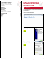
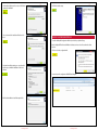
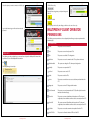
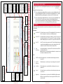
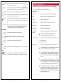
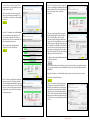
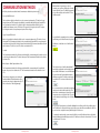
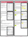
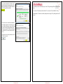
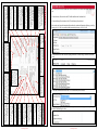
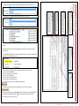
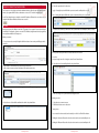
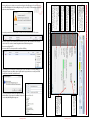
MULTIPATH IP USER MANUAL
INNER RANGE
For Version 5.0 Software
Table Of Contents
INSTALLING THE INNER RANGE MULTIPATH IP CLIENT5
INSTALLATION PROCEDURE
LOADING THE CONFIGURATION FILE
LICENSE KEYS
5
7
8
MULTIPATH IP CLIENT OPERATOR PERMISSIONS9
STU PERMISSIONS
9
SYSTEM ADMINISTRATION
10
SYSTEM PERMISSIONS
10
SYSTEM ADMINISTRATION OPTIONS
10
LICENSE KEYS
11
CREATING / EDITING A USER11
ADDING A NEW USER
11
DELETING AN EXISTING USER
13
EDITING AN EXISTING USER
13
CREATING / EDITING BUREAUS13
INNER RANGE MULTIPATH IP CLIENT OVERVIEW14
THE MULTIPATHIP CLIENT LAYOUT
15
HOME MENU
15
MONITORED & UNMONITORED STU’S
17
SORTING AND ARRANGING THE MONITORED AND UNMONITORED LISTS
20
SORTING BY COLUMN HEADER
21
REMOVING A COLUMN
21
ADDING / RESTORING COLUMNS
21
REARRANGING COLUMNS
22
GROUPING BY COLUMNS
22
REARRANGING COLUMN GROUPS
22
RESIZING COLUMNS
23
CONTROLLING STU
23
STU ENROLLMENT PROCESS25
SERIAL STU, PREMIER STU & OMNILINK
25
COMMUNICATION METHODS28
STU ENROLLMENT PROCESS - E-LINK
30
STU ENROLLMENT PROCESS - SKY TUNNEL DEVICE
31
STU DETAILS33
STU DETAILS - STU PROGRAMMING
34
PRE-ENROLLING A STU
35
STU DETAILS - REMOTE CONTROL
37
INTEGRITI / CONCEPT AUTHENTICATION
38
ACTIONS38
STU DETAILS - REMOTE CONTROL SKY COMMAND
40
STU DETAILS - PATH TEST
42
UN-ENROLING PARAMETERS
43
STU COMMUNICATION DIAGNOSTICS
45
Inner Range / Fratech MultipathIP Client
User Manual: Revision 5.0
For MultipathIP Client software version 5.0
May, 2014
© Copyright 2006-2014
Inner Range Pty. Ltd.
Disclaimer:
1. The manufacturer and/or its agents take no responsibility for any damage, financial loss or injury caused to any equipment, property or persons resulting from the
correct or incorrect use of the Inner Range system and its peripherals. The purchaser
assumes all responsibility in the use of the Inner Range system and its peripherals.
2. Whilst every effort has been made to ensure the accuracy of this manual, Inner
Range Pty Ltd assumes no responsibility or liability for any errors or omissions. Due
to ongoing development the contents of this manual are subject to change without
notice.
Multipath IP User Manual Version 5.0
Page 2
© Inner Range PTY LTD
Multipath IP User Manual Version 5.0
Page 3
© Inner Range PTY LTD
STU DETAILS - ALARM PANEL PROGRAM INPUTS
46
STU DETAILS - ALARM PANEL MANAGE USERS
47
CONFIGURING A STU FOR USE AS AN ALARM PANEL
48
SYSTEM STATUS
50
MESSAGE VIEW
51
USING MESSAGE VIEW
52
PRINT PREVIEW
54
AVAILABILITY REPORT
56
UNDERSTANDING THE AVAILABILITY REPORT
57
CONFIGURATION OPTIONS
58
GLOSSARY60
NOTES61
NOTES62
INSTALLING THE INNER RANGE MULTIPATH IP CLIENT
INSTALLATION PROCEDURE
The following procedure describes the process involved in installing and configuring the Inner Range /
Fratech Client for first time use.
Start by locating and running the client setup package.
If any applications are running, close them and click Next
to continue the installation .
Read and accept the End User License Agreement then
click Next to continue the installation.
Multipath IP User Manual Version 5.0
Page 4
© Inner Range PTY LTD
Multipath IP User Manual Version 5.0
Page 5
© Inner Range PTY LTD
Confirm the installation path is correct and click Next to
continue the installation
Click Finish to exit the setup.
Choose the name of the installation folder then click
Next
LOADING THE CONFIGURATION FILE
To load the MultipathIP configuration file that is provided to you by Inner Range.
Run the MultipathIP Client from the Windows Start button. An error should occur when the client launches:
Click Yes to load the configuration file.
Confirm the installation settings are correct then click Install to proceed with the installation of the client software.
Locate and open the configuration file MIPClientConfig.xml
Wait for the installation to install the required files.
Multipath IP User Manual Version 5.0
Page 6
© Inner Range PTY LTD
Multipath IP User Manual Version 5.0
Page 7
© Inner Range PTY LTD
Select the system you want to connect to and click Login.
Click Add License Key
Enter the license key given to you by Inner Range and
click OK
Click Close to finish.
Note: If your system is hosed by Inner Range you will not need to enter a license key.
MULTIPATH IP CLIENT OPERATOR PERMISSIONS
Log into the client using your allocated user name and
password.
The following operator permissions can be configured by Inner Range to suit your requirements for individual logins:
STU PERMISSIONS
Create
The operator can create a new STU.
Enrol
The operator can enrol newly created STUs.
Edit
The operator can edit the STU configuration.
Hard Reset
The operator can send a command to the STU to perform a hard reset.
Click
Edit Alarm Panel
The operator can change the STU alarm panel configuration.
Followed by Manage License Keys.
Stand-By
The operator can suspend the STU.
Un-Enrol
The operator can un-enrol a STU.
Delete
The operator can delete STUs.
Service
The operator can enable remote access to the alarm panel attached to the
STU.
Diagnostics
The operator can view STU diagnostic information.
Send Command
The operator can send commands to the STU. (Should only be done under
instruction from Inner Range).
Control On
The operator can turn on Auxiliaries and dependent on STU and panel configuration, home Auxiliaries and Areas on the connected panel and STU.
Control Off
The operator can turn off Auxiliaries and dependent on STU and panel configuration, home Auxiliaries and Areas on the connected panel and STU.
Test Paths
The operator can test the communications paths to/from the STU.
Start PSTN Test
The operator is allowed to initiate a PSTN test of the STU.
LICENSE KEYS
The following procedure explains how to enter new license keys into the Multipath IP software. At the
top left-hand corner of the MultipathIP client window
Multipath IP User Manual Version 5.0
Page 8
© Inner Range PTY LTD
Multipath IP User Manual Version 5.0
Page 9
© Inner Range PTY LTD
Edit Remote Control
The operator can set parameters to control Concept home aux and areas.
LICENSE KEYS
SYSTEM ADMINISTRATION
At the top left-hand corner of the MultipathIP client window click
Global
The operator is permitted access to the Global system administration screen.
Users
The operator is permitted access to the Users system administration screen.
Followed by Change Password.
Bureaus
The operator is permitted access to the Bureaus system administration screen.
Messages
The operator is permitted access to the Messages system administration
screen.
Enter your old password and enter your new password.
Re-enter your new password and click OK to finish.
Plans
The operator is permitted access to the Plans system administration screen.
Network Profiles
The operator is permitted access to the Network profiles system administration screen.
R/L Mappings
The operator is permitted access to the R / L Mappings system administration
screen.
CREATING / EDITING A USER
SYSTEM PERMISSIONS
Show System Status
The operator can access the system status.
Can View System Messages
The operator can view system messages.
Can Perform Database The Operator can Perform database snapshots.
Snapshot
SYSTEM ADMINISTRATION OPTIONS
System Administration Options are accessible to administrative operators.
The window column headings are as follows:
User Name The name used to log in to the MultipathIP client software.
To access the Administration options click Full Name
followed by the icon.
We strongly recommend that you consult your Inner Range technical representative before changing any
options in this area unless you are Absolutely CERTAIN you know what you are doing and what impact it could
have on your system.
Only the Users and Bureaus menus are explained. The other accessible items have been excluded intentionally.
The actual name displayed for the MultipathIP client user.
Description An optional field to describe the user.
Disabled
A check box item used to disable the user account. The user will not be able to log in again
until this is unchecked.
Locked Out This check box item is reserved for future use.
ADDING A NEW USER
Click the Add New button to open the Editing User dialog:
Multipath IP User Manual Version 5.0
Page 10
© Inner Range PTY LTD
Multipath IP User Manual Version 5.0
Page 11
© Inner Range PTY LTD
Start by entering a name for the User – This will be what the user will use to log in with.
DELETING AN EXISTING USER
Next enter the Full Name of the user.
To delete a user from the user list select the user then click the Delete Item button. The user is deleted
immediately and this cannot be undone.
Select the Bureau for the user if required. Refer to the next section for more detail on Bureaus.
If you have accidentally deleted a user, you will need to re-create the user by clicking the
button.
Enter a description for the user.
If you want to prevent the user from changing his/her password check
the can’t change own password check box.
EDITING AN EXISTING USER
If you want to stop a user logging in to the Multipath IP client, check the
Account is disabled check box. This is a good alternative to deleting a
user if you think the user might need access again in the future.
To edit a user, highlight the user record then click the Edit Item button. The Editing User window will
appear. This process is similar to adding a new user.
Once you are ready click Change Password and assign a unique password to the user.
CREATING / EDITING BUREAUS
Bureaus are used to divide STUs and operators in to groups.
Click on the “User Permissions” tab.
Enter the name of the Bureau.
Check the appropriate STU permissions for the user.
Give the Bureau an appropriate description.
Check the appropriate System Administration options for the user.
Tick the Allow Remote Login check box if want to allow
users in this Bureau to be able to login remotely.
Check the appropriate System Permissions for the user.
The Create Client Config button is an advanced option.
Consult your Inner Range support representative for more
information.
Click Save Changes to save the user then close the window.
Multipath IP User Manual Version 5.0
Page 12
© Inner Range PTY LTD
Multipath IP User Manual Version 5.0
Page 13
© Inner Range PTY LTD
Control
Remote control actions
can be exercised.
Diagnostics
Click on this button to see the status
of the GSM, GPRS and Ethernet paths.
GPRS can be started and the SIM card
can be swapped.
Availability Report
Click on this button to see the
availability for each STU for the
selected duration.
GSM Signal
Strength This area
shows the current
signal strength for
each STU.
Path State This area shows the
current path state
for each STU. See
details below.
Fault Indicators
This area shows the
current faults that
are present for each
STU. See details
below.
System Status
Click on this button to see MultipathIP current system status. This includes things like: the Automation System connections, SMS connection etc.
INNER RANGE MULTIPATH IP CLIENT OVERVIEW
Edit STU Config
Click on this button
to see and edit the
detailed configuration
of the STU.
Enrol New STU
Click on this button to
start the enrolment of
a new STU. This is how
units in the field are
configured to communicate to the Multipath
system.
Monitored STUs
STUs in this section are
being monitored for
“Loss of Polling”.
STU Status Indicators
This column indicates
the status of each STU.
See details below.
Unmonitored STUs
STUs in this section are
not being monitored
for “Loss of Polling”. To
start monitoring a STU,
click on the STU and
then click Enrol STU.
Version Information
This section shows the
version information for
the MultipathIP Client
and the MultipathIP
Server.
MultipathIP Client status
This area shows the current MultipathIP Client connection status. See
details below.
Multipath IP User Manual Version 5.0
Page 14
© Inner Range PTY LTD
THE MULTIPATHIP CLIENT LAYOUT
The bottom right-hand corner of the MultipathIP Client indicates the status of the connection to the
server.
Multipath Client Connection Status
This icon indicates that the Multipath Client is currently connected to the Multipath Server. This
means that the Multipath Client will receive live updates from the Multipath Server, so that the
Multipath Client will always be displaying the current state of the STUs and the system.
This icon indicates that the Multipath Client is not currently connected to the Multipath Server.
The state of all of the STUs and the system at the time when the Multipath Client was disconnected from the Multipath Server will remain displayed on the Multipath Client. If the previous connection to the server is lost, the Multipath Client login will reappear.
HOME MENU
At the top of the client window is the home menu bar. It provides quick access to the most commonly
used functions:
Enrolment
Enrol New STU Click on this button to start the STU Enrolment Wizard. This is how units in the
field are configured to communicate to the Multipath system.
Pre-Enrol STU
Click on this button to start the pre-enrolment of a new STU. This is used to set
the detailed configuration of a STU prior to the STU actually communicating
with the Multipath system. Pre-enroled STUs are placed in Unmonitored STUs.
Enrol STU
Enrol STU is used to bring an unmonitored STU online. Clicking this button will
open the Enrolment Wizard allowing you to make changes before the STU is
enrolled. The enrolled STU will move into the Monitored STUs.
Start
Monitoring
Start Monitoring will move a suspended STU from the Unmonitored STUs list
to the Monitored STUs list.
Note: Unenroled STUs require the Enrolment Wizard to be completed to come
back online into the Monitored STUs list.
STU
Edit STU Config Click on this button to see and edit the detailed configuration of the selected STU.
View STU
Messages
Click this button to see the history of events relating to the selected STU.
Hard Reset
Click on this button to open the Hard Reset dialog in order to reset a problem STU.
Control
Click on this button to open the Remote Control dialog and perform remote
control actions.
Diagnostics
Click on this button to see the status of the GSM, GPRS and Ethernet paths.
GPRS can be started, the SIM card can be swapped and a PSTN test can be
started manually.
Multipath IP User Manual Version 5.0
Page 15
© Inner Range PTY LTD
Send Cmd Click on this button to open the STU Terminal screen. This screen is most commonly only used by Inner Range.
MONITORED & UNMONITORED STU’S
The middle and lower sections of the client window displays all of the STUs and their status.
Service
Click on this button to open the Remote Dial-In dialog and allow the technician a
time period to be able to dial into the alarm panel via the PSTN.
Write STU
Click on this button to perform the Write Programming operation on a STU.
Suspend
Click on this button to suspend monitoring of “Loss of Polling” for the selected STU
and move the STU to the Unmonitored section.
Unenrol
There are a total of 34 different columns for displaying STU information:
Column Headings
Click on this button to stop monitoring the selected STU and move the STU to the
Unmonitored STUs section. Pressing this button will halt communications with the
STU.
Delete STU This button will only be enabled when clicking on a STU that is in the Unmonitored
section and the STU status is New or Unenroled. Clicking on this button will permanently remove the selected STU from the Multipath system.
System Manager
Event
Messages
Click this button to see the history of system wide events.
Auto System Click this button to see the events sent to the automation system.
Output
System
Messages
Backup Phone
The phone number of the second SIM. (Not always populated).
Bureau
The Bureau that the STU is assigned to (blank if no Bureau).
Client Code
The client code given to the STU
Current SIM Card
The number of the SIM card last detected to be in use.
Date Enrolled
The date the STU was first enrolled.
Date Unenroled
The date the STU was last unenroled.
Disable PSTN Line
Monitoring
A tick box option to indicate whether the PSTN line is monitored.
Ethernet Card Present
A tick box option to indicate whether the STU has an Ethernet card.
Click this button to see the history of system messages.
Ethernet card present
Ethernet card not present
Reports
Fault Indicators
Availability
Report
Click on this button to see the availability for each STU for the selected duration.
System Status
Click on this button to see MultipathIP current system and network status. This
includes things like: the Automation System connections, SMS connection etc.
The STU is not programmed to monitor the PSTN line.
The STU is programmed to monitor the PSTN line.
Displays power, battery, phone and panel connection status icons.
This icon indicates that the STU has detected that there is no AC power
supply connected. This fault cannot occur on a Serial STU.
System
This icon indicates that the STU has detected that there is no battery
connected. For a Premier STU this may be that the connected battery is
‘dead’. For other STUs this may be that the power supply powering the
STU is low.
This icon indicates that the STU has detected that there is no PSTN line
(phone line) connected to the STU. This fault can only occur on a Premier
STU. If it is known that there is no PSTN line on site this can be cleared by
selecting “Disable PSTN Monitoring” from within the Edit STU Config.
This icon indicates that the STU has detected that there is no serial communications with the connected alarm panel. For all types of STUs this
means that there is no alarm communications with the alarm panel. In
the Edit STU Config, if the Communication Mode is selected to be “Dialer
Capture” this fault will not occur.
Multipath IP User Manual Version 5.0
Page 16
© Inner Range PTY LTD
Multipath IP User Manual Version 5.0
Page 17
© Inner Range PTY LTD
not allowing the data from the Multipath system to reach the STU as it is
configured incorrectly.
This icon indicates that the STU is currently running
deprecated firmware. It is recommended that you upgrade the STU to
the latest version.
GSM Network
Indicates the GSM network type on newer STU models. Eg. 2G, 3G.
GSM Signal Strength
The signal strength bar.
Line Access Prefix
The digit that the alarm panel dials first to gain access to the PSTN line.
Not available on Serial STUs.
Modem Type
The model of the modem used in the STU.
Monitoring State
Will display Enrolled, Unenroled or Enrolling.
Number of Sim Cards
This path state colour indicates that the path is not available in the plan
selected for the STU.
Plan
Name of the plan the STU is enrolled under.
Primary Phone
The phone number of the primary SIM.
PSTN Line Present
A tick box option to indicate whether the PSTN line is present.
- Present
- Not present
R/L
The receiver number / line number.
Remote Access Mode
Displays the available remote access type. Can be Fax bypass, No access or
Always Allow (Not available for Serial STUs).
The total number of SIM cards in the STU.
Reporting Format
Will display ContactID, IRFast or IRFastText
Online State
Will display Online, Offline or On Backup Path.
Securitel Panel Type
PABX Prefix
The digit the STU must dial as a prefix to gain access to a PSTN line.
Displays the type of panel the STU is connected to if using Securitel communications. Can be Default, IR Concept 3000, DAS / NX, IR Concept 2000,
Challenger (GE / Tecom), Solution (Bosh / EDM) or DSC.
Panel Communications
Method
Will display Concept, Securitel or Dialer capture.
Serial Number
The serial number of the STU.
Panel Watchdog Mode
If panel monitoring is enabled, this column will display watch dog, cable
tamper or zone
SIM 1 Serial
The serial number of the 1st SIM card.
SIM 2 Serial
The serial number of the 2nd SIM card.
Path State
Path states can be online, offline, path warning, Idle, not available or not
in selected plan
Site Name
The name given to the STU for the site.
Status
Will display Online, Offline, Backup Path, Unenroled, Enrolling online or
Enrolling offline.
This path state colour indicates that the path is good. It indicates that the
path is in use and is working correctly.
This icon indicates that the STU is online and working correctly.
This path state colour indicates that the path is idle. It indicates that the
path is not in use but can be used by the STU.
This icon indicates that the STU is offline (not communicating with the
Multipath system).
This path state colour indicates that the path is faulty. It indicates that
the path is not in use and has not worked correctly for a period of time
(this time is configurable per STU in the Edit STU Config in the “Path Test”
section). When a path turns this colour an event is sent to the Automation System to indicate that there is a fault.
This icon indicates that the STU is online, working correctly but is using a
backup path. If the STU stays in this state until one of its paths goes the
red fault colour, service/a technician should be contacted.
This icon indicates that the STU has been unenroled from the Multipath
system. This means that the STU has been told not to communicate any
alarms to the Multipath system. This icon will only be shown for a STU in
the Unmonitored STUs section.
This path state colour indicates that the path is in one way communications. It indicates that the path is in use but is not working correctly. This
colour indicates that the STU can send data to the Multipath system but
when the Multipath system is sending data back to the STU, the data is
not being received at the STU. This fault will most commonly occur for a
STU on the Ethernet path where the network at the customers site is
Multipath IP User Manual Version 5.0
Page 18
© Inner Range PTY LTD
This icon indicates that the STU has been suspended. This means that
there will be no online or offline events sent to the Automation System
Multipath IP User Manual Version 5.0
Page 19
© Inner Range PTY LTD
when they occur for this STU. This icon will only be shown for a STU in
the Unmonitored STUs section.
SORTING BY COLUMN HEADER
All of the list items can be sorted by any of the columns.
This icon indicates that the STU is going to be enrolled or is currently in
the process of being enrolled.
To change which column you want to sort by, click on the column header.
To change the sort method from ascending to descending, click the column header again to toggle.
Type
The type of STU. Can be Premier, Serial or OmniLink.
Version
The STU firmware version.
REMOVING A COLUMN
Enable ademco fast
A tick box option to indicate whether the Ademco Fast line is enabled.
To remove a column, click and drag it out of the column header area. Your
mouse cursor will change to a (X) to indicate that if you release your mouse button, the column will be removed.
An icon
- Ademco Fast is enabled.
- Ademco Fast is disabled.
Auto Time Sync to
Server
or
will appear on the column header that is currently being sorted.
Alternatively, right-click the column header and select Remove Column.
A tick box option to indicate whether the AutoSync is enabled. This requires path test feature to be enabled.
- The STU is programmed to get time sync from server.
- The STU is not programmed get time sync from server.
Disable AC Fail
A tick box to indicate whether the AC Fail message has been disabled.
- The STU is programmed to not send AC Fail Messages.
- The STU is programmed to send AC Fail Messages.
SORTING AND ARRANGING THE MONITORED AND UNMONITORED LISTS
The Monitored and Unmonitored lists have powerful and flexible display options to help display the listed STUs in a format suitable to the operator.
ADDING / RESTORING COLUMNS
These display options, when configured, will persist for as long as the client application is running. Closing the client application will loose the configured display options.
Group by box
Column header
To add / restore a column, right-click the column header area and select
Column Chooser. The column header customisation window will appear from
which you can drag columns in to the column header area.
Column text filter
Note: The re-arranged UI is not saved for the next time that the operator logs on..
Multipath IP User Manual Version 5.0
Page 20
© Inner Range PTY LTD
Multipath IP User Manual Version 5.0
Page 21
© Inner Range PTY LTD
REARRANGING COLUMNS
RESIZING COLUMNS
All columns can be rearranged easily by clicking and dragging them to a new location amongst the column headers.
To resize a column, move the mouse to the right hand edge of the column you want to resize.
Once your mouse cursor has changed to a
GROUPING BY COLUMNS
you can click and drag to adjust the size of the column.
Alternatively, right-click the column and select Best Fit to automatically adjust
the column size.
The Group by box allows the user to drag any of the columns in to this space. By doing so, the list view
will be broken up in to groups according to the information normally displayed in the column(s).
To adjust all of the columns at once, right-click any column and select
Note
You can hide or show the group by box by right-clicking a column and selecting
REARRANGING COLUMN GROUPS
CONTROLLING STU
If you have more than one column header in the ‘group by box’ then you will be able to rearrange the
order in which users are grouped.
You can access STUs configured for remote control by clicking on the Control button in the main window
tool bar.
Click and drag the column to the left or the right of its current position to relocate.
Resizing columns
Depending on the STU configuration you will see one or two control tabs.
Multipath IP User Manual Version 5.0
Page 22
© Inner Range PTY LTD
Multipath IP User Manual Version 5.0
Page 23
© Inner Range PTY LTD
STU ENROLLMENT PROCESS
SERIAL STU, PREMIER STU & OMNILINK
The STU Enrolment Wizard easily assists the operator to configure the STU to be monitored by the Multipath Server.
- Clicking this button will turn the output on. If the output is already on, nothing will
change.
- Clicking this button will turn the output off. If the output is already off nothing will
change.
To start the STU Enrolment Wizard, click the Enrol New STU button at the top left of the Multipath IP software.
On Screen 1 the STU phone number, client code and
site name are entered. After these values have been
entered click Next.
- To determine the state of the output click this button. The state of the output is
displayed to the right of this button.
On Screen 2 the plan that the STU will be using is
selected. This selects the monitoring level and polling rates that the STU will use and the billing
cost to the monitoring station.
- Clicking this button will arm the STU alarm panel.
- Clicking this button will disarm the STU alarm panel.
After the appropriate plan has been selected click
Next to start communications with the STU.
- Clicking this button will refresh the zone and alarm panel states.
- Clicking this button will Isolate any of the selected zones and De-Isolate any un
selected zones.
Multipath IP User Manual Version 5.0
Page 24
© Inner Range PTY LTD
Multipath IP User Manual Version 5.0
Page 25
© Inner Range PTY LTD
If the STU has dual SIM cards and the operator has
selected a single SIM plan, the Multipath Client will
halt the enrolment. This is a bad configuration and
must be changed in order to continue the enrolment.
On Screen 3 the you are able to assign a STU to a
particular Bureau, in order for the Bureau to have
partial control over the STU.
After a selected Bureau has been selected click
Next to start communications with the STU. You
are also able to choose (None) for a Bureau, if there
is no Bureau.
Once the STU has initially contacted the Multipath
Server, the Multipath Server will query the STU
for its hardware configuration. The results are displayed for the operator to confirm that the STU
has the settings that are expected.
This screen is only displayed if the selected plan
includes the Ethernet path. The local IP address
of the STU (the IP address of the STU on the customer’s network) is displayed in the Ethernet
Status section. This may help if there are issues with
this site’s network configuration. The IP address can
be configured to be either DHCP or Static. DHCP is
the most common and means that the network at
the customer’s site will give the STU an IP address.
Static IP means that the STU will use the IP address
that the operator enters into this screen.
After checking that the displayed hardware configuration is as expected, click Next.
For further assistance with the Ethernet Status click
on theMore Help button.
All of the Ethernet status values should have a green tick. If some of them are not ticked but have a blue
cross ( ) instead, further assistance with the Ethernet Status can be obtained by clicking on the More
Help button.
Regardless of whether or not all of the Ethernet Status has green ticks, the enrolment can continue.
Click Next to continue the Enrolment.
If the STU only has a single SIM card and the plan
that was selected is for a STU that has dual SIM
cards, the Multipath Client will display a warning to
the operator that there may be an issue. A dual SIM
plan also cost the monitoring station more than a
single SIM plan so this would not be desirable for
the monitoring station.
Multipath IP User Manual Version 5.0
This Screen capture shows the Reporting Format
and alarm panel Communications Method. The Reporting Format will have some options grayed
out depending on the Communications Method
that has been selected and the firmware that the
STU has. The Communications Method will display
different options in the list depending on the type
of STU (Premier or Serial) and the firmware that the
STU is on.
Page 26
© Inner Range PTY LTD
Multipath IP User Manual Version 5.0
Page 27
© Inner Range PTY LTD
COMMUNICATION METHODS
Whilst the Write Programming procedure is executing, a progress bar is displayed to show the
operator where it is up to. The Write Programming
process will usually proceed faster if the STU has
the Ethernet path.
All of the options that are available in the Communications Method drop down box are:
Concept 3/4k GSM Protocol
This is used when a High-Level interface is used to communicate between the STU and the Concept/
Integriti alarm panel. This Communications Method is compatible with both IRfast and ContactID. The
Concept alarm panel must be V5.70 or higher for this Communications Method. IRfast Test is also available in later firmware versions. The Premier STU requires V2.62 or higher, the Serial STU requires
V2.42 or higher and the Concept alarm panel requires V7.80 or higher.
Legacy Concept GSM Protocol
When a Concept High-Level interface will be used to communicate between the STU and the Concept
alarm panel. This Communications Method is only compatible with ContactID. The Concept alarm panel
can be between V4.06 and V5.69 for this Communications Method. This Communications Method is available for Premier STUs (V2.62+), Serial STUs (V2.42+) and OmniLink STUs.
Once the Write Programming has been completed
the following screen will be shown to the operator.
Click Next to see the final screen of the Enrolment
Wizard.
Securitel
The Communications Method is for all alarm panels that will be communicating the Securitel protocol via
a serial connection between the STU and the alarm panel. This Communications Method is not available
for Premier STUs.
Dialer Capture + Dialer Capture (Ademco Fast)
This is the final screen of the Enrolment Wizard. To
immediately complete the enrolment the operator
must click theFinish button. Once the Finish button
has been clicked the Enrolment Wizard window
will disappear and the STU will be moved from the
Unmonitored STUs section to the Monitored STUs
section.
The Communications Method is for all alarm panels that will be communicating the ConctactID and
Ademco Fast protocol via a dialer to the STU. This Communications Method is not available for Serial
STUs.
This is the last configuration screen during the Enrolment Wizard. Click the Next button to program the entire selected configuration to the STU
(this is referred to as "Write Programming").
It is a recommended procedure that the monitoring
station exercises the available paths of the STU as
part of their commissioning procedure. If the monitoring station chooses, the paths of the STU can be
exercised at this point by clicking on the Test Paths
button.
As soon as the Test Paths button is clicked the Multipath Server will exercise all of the available paths of
the STU. Whilst each of the paths is being exercised the progress bar will increment. When the Path Test
process has been completed a summary will be displayed on the screen.
To complete the enrolment the operator must click Finish. Once the Finish button has been clicked the
Enrolment Wizard window will disappear and the STU will be moved from the Unmonitored STUs section
to the Monitored STUs section.
Multipath IP User Manual Version 5.0
Page 28
© Inner Range PTY LTD
Multipath IP User Manual Version 5.0
Page 29
© Inner Range PTY LTD
STU ENROLLMENT PROCESS - E-LINK
STU ENROLLMENT PROCESS - SKY TUNNEL DEVICE
To Enrol the E-link STU start by using
MPEthernetSetup.exe. Once the information has been
filled in click on the program button.
The Enrolment Wizard easily assists the operator to configure the STU to be monitored by the Multipath Server
To start the STU Enrolment Wizard, click the Enrol New
STU button
On the Multipath IP software you will see the STU display
under the unmonitored Stu’s section.
The STU phone number does not need to be entered, instead tick the Sky Tunnel Details radio
button. Enter the STU serial, Client code and site
name. After these values have been entered click
Next.
From there continue to enrol the Stu by following the
instructions below.
The plan that the STU will be using will need to be
selected. Select a Sky Enabled plan for Sky Tunnel
reporting. After the appropriate plan has been selected click Next to start communications with the
STU. Click Next to proceed.
The Multipath STU Enrolment Wizard easily assists the
operator to configure the STU to be monitored by the
Multipath Server for the Ethernet Stu. The first two stages
are different, then revert to Serial Stu enrolment instructions.
To start the STU Enrolment Wizard, click the Enrol New
STU button
The STU phone number does not need to be entered, client code and site name are entered. After these
values have been entered click Next.
On Screen 3 the you are able to assign a STU to a
particular Bureau, in order for the Bureau to have
partial control over the STU.
Note:
For Ethernet only STU’s the Ethernet STU must be online and communicating with the server. If it is not communicating, the enrolment wizard will ask you to input a phone number.
After a selected Bureau has been selected click
Next to start communications with the STU. You
are also able to choose (None) for a Bureau, if there
is no Bureau. Click Next to proceed.
Please refer to the Ethernet STU enrolment/configuration installation manual, on how to successfully configure the STU.
The plan that the STU will be using will need to be
selected. An Ethernet Only plan must be picked in
order for the next stage to work.
After the appropriate plan has been selected click
Next to start communications with the STU.
Multipath IP User Manual Version 5.0
Page 30
© Inner Range PTY LTD
Multipath IP User Manual Version 5.0
Page 31
© Inner Range PTY LTD
STU DETAILS
A progress bar is displayed to show the operator
what point the write programming it is up to. The
Write Programming process will proceed faster if
the STU is using a Sky Tunnel Path.
The following 3 sections describe the purpose of the STU Programming, Path Test and Remote Control
tabs.
To access the STU details, either double-click the STU or select the STU and click Edit STU Config
Additionally, the STU details screen will be displayed when creating a STU by clicking the Pre-Enrol STU
button.
This is the final screen of the Enrolment Wizard. To
immediately complete the enrolment the operator
must click theFinish button. Once the Finish button
has been clicked the Enrolment Wizard window
will disappear and the STU will be moved from the
Unmonitored STUs section to the Monitored STUs
section.
Sky Tunnel does not require a path test to be done.
Click Finish to proceed.
Multipath IP User Manual Version 5.0
Page 32
© Inner Range PTY LTD
Multipath IP User Manual Version 5.0
Page 33
© Inner Range PTY LTD
1. Enter the name of the site where the STU will be installed in the Site Name field.
2. Enter the Primary Phone Number of the STU in the Primary Phone No field.
If the number isn’t entered in international format then the number will automatically change to suit. Eg.
Entering 0410 011 422 is acceptable and will automatically change to +61410 011 422.
Bureau
The Bureau that this STU is assigned to.
Bureau users can only see, test, administer etc. STUs that they have been
assigned.
Plan
This selects the network and the monitoring level that the STU will be using.
Reporting Format
This selects the format that will be
reported by the STU to the Automation
System. NOTE: These options can be
grayed out depending on the STU or
other selected options.
Client Code
The value in this field will match up with
the value entered into the Automation
System.
Primary/Backup Phone No
These fields shows the SIM card phone
numbers. If there are 2 SIM cards
installed in the STU it is recommended
that the Backup SIM phone number be
entered.
Site Name
This field shows the name of the site.
Save Changes
This button allows the user to save
changes that have been made to be
saved to the Multipath Server. NOTE:
For changes that have been made to be
sent to the STU, the Write Programming
button must be clicked.
4. Select the plan that the STU will be enrolled on.
Hardware Info
This section displays the hardware
information about the STU. This
information is queried from STU
by the Multipath Server.
5. Select the Communication Mode of the STU to suit the alarm panel connected.
Send Port No
This is the UDP port number that the STU will use as
its “source port” when sending data to the Multipath
Server. If there is more than 1 STU on the same site
each STU should have a unique Send Port No. NOTE:
If this is left at the default value of 0 then the STU
will be using port 41001.
Time Zone
This sets the time zone that
the STU is in. By setting the
time zone to be correct for
the STUs location, the correct time will be in the STU.
Write Programming
This button allows the user to write all of the
configuration to the STU. NOTE: For changes
that have been made to be sent to the STU, the
Write Programming button must be clicked.
3. Enter the Client Code and select the reporting format the STU will be using to communicate with the
server.
Ethernet Configuration
This displays the currently configured settings for
a STU that is using Ethernet. These settings can be
changed at any time and can then be sent to the
STU by clicking the Write Programming button.
For a STU that is not using Ethernet this section
can be ignored.
Cancel Changes
This button allows
the user to discard
all changes that have
been made.
STU DETAILS - STU PROGRAMMING
A STU can be pre-enroled to minimise the amount of time taken to commission it when it is deployed on
site.
Communications Mode
This section allows the user to select the communications
mode that will be used by the STU to communicate with
the connected alarm panel. NOTE: The Panel Type option is
grayed unless “Securitel” is selected in the Communications
Mode
Line Access Digit
This set the number that the alarm
panel must dial in order to access
the PSTN line through the STU
Alarm Panel Monitoring
This sets the hard wired alarm panel
monitoring method for a Premier
STU.
Locked to Server
By setting this check box the STU
cannot be manually defaulted by a
technician on site.
Disable PSTN Monitoring
By setting this check box the PSTN
connected to the STU will not be
monitored.
PSTN Dial Prefix
This sets the number that the STU
must dial in order to access the
PSTN line on site. This is commonly
used when there is a PABX on site.
Disable AC Fail
By setting this check box the AC Fail
will not be monitored by the STU.
AutoSync Time to Server
By ticking this check box the STU
will Sync the time to the time on the
server.
Network Type
Newer STUs will display network
type. Eg. 2G or 3G.
6. If PSTN is not going to be used on a Premier STU, you can disable monitoring of the line by clicking the
Disable PSTN Monitoring check box.
Remote Panel Access
This sets the alarm panel access
method via the PSTN for a Premier
STU. It is used to configure how the
technician can “dial into” the alarm
panel
© Inner Range PTY LTD
© Inner Range PTY LTD
Page 35
Multipath IP User Manual Version 5.0
Page 34
Multipath IP User Manual Version 5.0
PRE-ENROLLING A STU
STU DETAILS - REMOTE CONTROL
SkyCommand Users
This button allows the central station to setup
SkyCommand end users to have the ability to
control the remote control options set by the
Bureau or Control Station.
Please Note: STU time will be synchronized during a path test. The path test feature must be enabled for AutoSync to work.
11. Select Disable AC Fail if the STU is connected via battery. This feature is used when a constant AC fail
Signal appears on the multipath client screen.
Test Settings
The Test Settings button can be used to verify that
the correct authentication has been provided by the
technician. Once this button has been clicked the
status will be displayed next to the button.
12. The notes field is a useful space to enter any miscellaneous information. For example•The STU’s location within a building.
• The keys or access required to get to the STU.
• The Location of the STU’s antenna.
• The location of the circuit breaker the STU.
• The name of the commissioning technician.
13. Click Save Changes once you have completed entering your data.
14. Click Write Programming to write the configuration to the STU so it can be monitored.
15. When you close this window you will notice that the STU is in the unmonitored STU list. Click the STU
in the unmonitored list then click Enrol STU (
) to move the STU to the monitored STU list.
Note SkyTunnel devices cannot be pre-Enrolled
Save Changes
This button allows the user to save changes that
have been made to be saved to the Multipath
Server. NOTE: For changes that have been made
to be sent to the STU, the Write Programming
button must be clicked.
Authentication
When controlling a Concept 3000 / 4000 alarm
panel, the permissions to perform these actions
will be authenticated by the alarm panel. The
technician on site will inform the control room
of these details.
Select the time zone that the panel will be situated.
© Inner Range PTY LTD
© Inner Range PTY LTD
Add / Delete Action
Create a new action by clicking on the Add
Action button. To delete an action, click on the
action to delete and then click the Delete Action
button.
8. If remote panel access is required, select the appropriate remote access option.
Page 37
Multipath IP User Manual Version 5.0
Page 36
Multipath IP User Manual Version 5.0
Action Configuration
To configure an action enter the details into the
fields available. Enter a Name, some notes (if an
explanation is desired or required) and select if
this action will be controlling a STU auxiliary or
a Concept entity. The second row of the action
will change depending on the selection that has
been made.
10. Select AutoSync time from Server to STU if needed. This requires the STU time zone to be set correctly.
This page allows control actions to be configured. The STU auxiliaries can be controlled and when a Concept 3000 / 4000 alarm panel is connected to the
STU via a High-Level interface, the Areas and Home Auxiliaries can also be controlled.
7. Change the Alarm Panel Monitoring to the method suitable for the alarm panel connected.
INTEGRITI / CONCEPT AUTHENTICATION
B. Select the operation mode for the action:
The Concept 3000 / 4000 High-Level Interface Authentication box allows for entry of an authorised SMS
number, a programmed PIN or both to authenticate access to the STU and the connected panel.
Toggle - Selecting this option will allow the operator to turn the auxiliary either on or off.
Pulse - Selecting this option will allow the operator to turn the auxiliary on for a set duration.
Use the Test Settings button to confirm the entered SMS number or PIN number is correct. A message to
the right of the button will indicate if the test was successful.
ACTIONS
Actions give operators the ability to control the STU, Integriti or Concept panel if connected via the high
level interface. If configured, operators can control STU auxiliaries, Integriti named actions, Integriti areas,
Concept home auxiliaries and Concept areas.
Adding a new action
C. If Pulse was selected then you will need to enter a pulse duration and a multiplier (either Sec or Min)
1. To create a new action, start by clicking the Add Action button. A new action panel will appear in the
action list:
If Concept was selected you will need to select either Area or Home Aux.
Please Note
If using an Integriti controller selecting Home Aux will control Named Actions
B. Select the Area or Home Auxiliary from the drop down list box:
2. Enter a Name to describe the purpose of the newly created action:
3. Click on Notes to enter an accurate description of the newly created action:
4. Select the device the action will be controlling either a STU or a Concept or Integriti Controller.
5. Click Save Changes once you have finished creating the action.
If STU was selected
Deleting an action
A. Select from one of the available auxiliaries in the Aux No drop down list box:
1. Select the action to want to remove.
2. Click Delete Action to remove the action.
Testing actions
Once an action has been created, it can be tested by use of the On, Off and Pulse buttons.
Clicking the On button will cause the selected action to turn its associated auxiliary/area on.
Clicking the Off button will cause the selected action to turn its associated auxiliary/area off.
Multipath IP User Manual Version 5.0
Page 38
© Inner Range PTY LTD
Multipath IP User Manual Version 5.0
Page 39
© Inner Range PTY LTD
Clicking the Pulse button will cause the selected action to turn its associated auxiliary/area on for a period of 5 seconds before turning it off again.
Removing a SkyCommand User
STU DETAILS - REMOTE CONTROL SKY COMMAND
SkyCommand is free and easy to use web application that is designed to remote control an alarm panel,
monitored by a Multipath IP STU using a smart phone or tablet. To use this free service to control your
alarm panel, your alarm panel must be monitored on the Multipath IP network using a Inner Range Multipath IP field device. Vist http://skycommand.innerrange.com/skycommand/ for more information.
To Remove a User, click on the email address (user) you would like to remove SkyCommand Functionality
from. Then proceed to “Remove Selected”.
SkyCommand Users Actions
Once this is successfully completed, the message below (With your STU) should appear.
Clicking Add Remote User will give you the ability to add a new user to SkyCommand.
Clicking Remove Selected will give you the ability to remove a SkyCommand user.
Clicking Add Remote User will produce the dialog below.
Adding a SkyCommand User
Enter in the Email address of the user (this acts as their user name) and click OK
If by selecting the tab Remote control > SkyCommand Users you are presented with the error shown
below. Please call Inner Range and ask for your newly connected STU to be updated in SkyCommand.
A Message will be received if successful. The list will now be updated to include the newly added SkyCommand user.
Multipath IP User Manual Version 5.0
Page 40
© Inner Range PTY LTD
Multipath IP User Manual Version 5.0
Page 41
© Inner Range PTY LTD
STU DETAILS - PATH TEST
Save Changes
This button allows the user to save changes that
have been made to be saved to the Multipath
Server. NOTE: For changes that have been made
to be sent to the STU, the Write Programming
button must be clicked.
PSTN Test Schedule
The automated PSTN test is configured by making the desired selection from the Recurrence
and Schedule Parameters options.
Test Schedule Recurrence & Schedule Parameters
The PSTN Test Schedule and Path Test Schedule allows for an automatic test of the communications
paths. Depending on the global system settings that was configured by Inner Range, these settings
might have already been set during the STU enrolment.
To start a scheduled test It is strongly recommended that the scheduled path tests are enabled.
1. Select either a Daily or Weekly re-occurrence.
2. Tick the box next to the time field.
Path Test
This page allows the configuration of the automated Path Test Schedule and the PSTN Test
Schedule. A manual Path Test can also be run by
clicking on the Test Paths button.
3. If Weekly was selected, click the boxes for days testing is required
4. Click Save Changes to finish.
Raise Path Warning
Path tests can report alarms to the Automation System if the schedule path test fails.
If 'Raise Path Warning if path has been offline for' has been set to a value above 0, then an alarm will be
transmitted to the Automation System after a failed Path Test if there has been no communications from
the STU via the path during the past set number of days. It is recommended that this setting is a value
above 0.
Polled Path test
A manual path test can be initiated by clicking theTest Paths button.
Path Test Schedule
The automated Path test is configured by making the desired selection from the Recurrence
and Schedule Parameters options.
Path Warning
The Path Warning configuration determines how long the Multipath System will wait before an event is sent
to the Automation System to report a
Path Warning.
Test Paths
By clicking the Test Paths button a path
test will be triggered straight away.
Multipath IP User Manual Version 5.0
Note Test Paths can be used to re-test a previously failed scheduled path test.
UN-ENROLING PARAMETERS
To un-enrol a STU, right-click the STU and click un-enrol in the drop down menu, Alternatively, left click
once to highlight the STU, then select un-enrol in the ribbon bar.
Page 42
© Inner Range PTY LTD
Multipath IP User Manual Version 5.0
Page 43
© Inner Range PTY LTD
STU COMMUNICATION DIAGNOSTICS
Path Status
The path status demonstrates three path icons
(Ethernet, GPRS 1 and GPRS 2). The Green icons
illustrate there is 2-way communications on
Ethernet and GPRS 1.
Yellow path state colour indicates that the path
is in one way communications.
Please refer to Path States indicated page 23.
Ethernet Status
Ethernet Status is a good indicator to diagnose
IP Network problems. It will illustrate
• If the Ethernet card on the STU is ok
• If the Ethernet cable is ok
• If the IP address is valid
GSM/GPRS Status
This shows the GSM Modem status (Online with
the Telstra (AU) Network, the IP Address it has
attained by Telstra. What Sim the STU is currently using and the current signal it has attached to
PSTN Status
Returns the Status of the PSTN actual Status by
checking the voltage. Dependent on the voltage
it will return a status.
Note If an E-Link is un-enroled, it will require a technician to go on site and re-initialise Ethernet settings in
order for the STU to continue communicating with the intended Monitoring Station.
Request cancellation for STU
An un-enrolled STU can be requested for cancellation of billing.
Right Clicking on an Un-enroled STU will allow you to send a cancellation to Inner Range Billing, by selecting the request cancellation option. It will prompt for your permission to execute your default
e-mail service to send the “cancellation email”.
Ethernet IP
The Ethernet IP Address illustrates
what IP the STU has been allocated
via DHCP or Static IP
Path Warning
The Path Warning configuration determines how long the Multipath System will wait before
an event is sent to the Automation
System to report a Path Warning.
Once OK is clicked your email service will have opened. It
will have filled out an composed e-mail that is ready to be
sent to [email protected]
© Inner Range PTY LTD
© Inner Range PTY LTD
Note If the Diagnostics windows is open for more than 30 minutes with no action given, it will automatically
close itself. In order to mitigate risk of consuming absorbents amounts of data
Once the password has been entered, the STU will be moved to the unmonitored STU’s section.
Page 45
Multipath IP User Manual Version 5.0
Page 44
Multipath IP User Manual Version 5.0
Path Test Commands
The path test commands allow you to:
• Start GPRS - Attain a GPRS IP address from the
network
• Swap Sim Card – Send a command to the STU
to go from SIM 1 to SIM 2
• Conduct a PSTN Test – Tests the Voltage on
the PSTN line and returns a Status in “PSTN Line
Status”
A dialog will pop-up to confirm your un-enrolment selection, this will prompt you for your login password. This will mitigate risk of un-enrolling the wrong STU or possibly a STU that cannot be recovered
without technician intervention.
STU DETAILS - ALARM PANEL MANAGE USERS
Save Changes
This button allows the user to save changes that
have been made to be saved to the Multipath
Server. NOTE: For changes that have been made
to be sent to the STU, the Write Programming
button must be clicked.
Manage Users
PIN codes can be allocated up to 32 users.
Program Inputs
Alarm panel mode can use up to 10 zones on
the STU.
User Number
A unique identifier that allows the central station to associate a user with a number.
Enabled
Allows the user to be active to be able to use the
panel.
Entry Delay & Exit Delay
These options allow a time for a user to activate particular
zones without generating an alarm during entry or exit.
STU DETAILS - ALARM PANEL PROGRAM INPUTS
Save Changes
This button allows the user to save changes that
have been made to be saved to the Multipath
Server. NOTE: For changes that have been made
to be sent to the STU, the Write Programming
button must be clicked.
Enable Alarm Panel Mode
Checking this option enables the STU alarm
panel functionality.
Siren Time
The time the siren will run for after an input has
changed to an alarm state.
Program Inputs
Alarm panel mode can use up to 10 zones on
the STU.
Manage Users
PIN codes can be allocated up to 32 users.
Write Programming
Once changes are made, to be active on the
STU, a write programming must be conducted.
User Name
Allows the Central Station to associate a
name to a user.
Pin
Allows the user to log in with a unique
code which is tailored to their user name
and user number.
Tamper Options
The STU can monitor the cabinet and key switch zones.
These zones are separate from the programmable inputs.
Remote Control
Ticking Allow Remote Arm / Disarm allows operators to control the STU
alarm functionality.
© Inner Range PTY LTD
© Inner Range PTY LTD
Page 47
Multipath IP User Manual Version 5.0
Page 46
Multipath IP User Manual Version 5.0
11. Change the zones to one of the 4 zone types.
CONFIGURING A STU FOR USE AS AN ALARM PANEL
The STU alarm panel mode allows the STU to operate as a single area 10 zone alarm system with a maximum of 32 users.
Initial setup
1. Tick Enable Alarm Panel Mode to start using the STU alarm panel feature.
• Instant – The panel will instantly send the panel into alarm
• Delay – Waits for a certain amount of time until panel goes in to alarm
• 24 Hour – Monitored for 24 hours
• Handover – Multi-state alarm.
12. Change arm options out of 3 different types.
2. If open and close reporting is required, click the Send Open / Close events tick box.
3. Change the entry and/or exit delay if required.
• Force Arm - The panel will arm normally even if the zone is unsealed.
• Auto Isolate -The panel will arm normally even if the zone is unsealed. Additionally, the zone will be
isolated.
• Deny Arm - The panel will not arm if the zone is unsealed. The operator will need to ensure the zone is
sealed before attempting to arm.
4. The configured siren time is the length of time the siren will run from the last input going in to an
alarm state.
13. If the input is not to activate the siren then tick the silent check box.
14. If operators should be allowed to isolate zones on the STU then tick the remote isolate tick box.
5. If the cabinet tamper is connected to Zone 12 then click the Enable Cabinet Tamper check box.
6. If a key switch is connected to Zone 11 then click the Enable Keyswitch Tamper check box.
7. Tick Allow Remote Arm / Disarm to give operators control over the alarm panel feature.
User programming
15. Click the Manage Users tab.
Input programming
16. To enable a user click the enabled tick box.
9. Enable zones by clicking the Enabled check box for each of the required inputs and enter a name to
describe the inputs.
Multipath IP User Manual Version 5.0
Page 48
© Inner Range PTY LTD
Multipath IP User Manual Version 5.0
Page 49
© Inner Range PTY LTD
Scenario:
There are two exclamation marks ( ) next to two items:
Search
Click this button to display the results in the results
window.
It is important that all items are ticked (
) in the status column. This indicates that the server communication paths are working, the server services are working and the alarm Automation System is
connected and working properly.
A blue cross (
) indicates that the item is not used or not configured for use.
If you have an orange exclamation mark (
) or red cross (
) then you should investigate further as
to exactly what the problem is.
MESSAGE VIEW
in the toolbar
To open the STU message view, click on the STU then click on the View STU Messages (
Search Parameters
The search parameters consist of
Date & Time
Client Identity
Message Direction
Paths
Message Types
Client Identity
Indicates what messages will be displayed
according to what is checked
To view the system status click on the System Status
Message Direction
Filters that can show messages from or to the
Stu, or From or to the Automation system
SYSTEM STATUS
Paths
Filters that can show messages from particular
paths, either Ethernet or GPRS
19. Click Save Changes when you’re completed.
20. Click Write Programming to write the programming to the STU.
Message types
Filters than demonstrate particular messages
from the STU, Events, Commands, Path Changes
etc.
Including Server messages such as processor
status, receiver status, etc.
Live Updates
As events occur the results window can be automatically updated.
17. Enter a name for the user.
18. Enter a PIN code for the user.
) button.
By clicking on the two plus (
) icons to the left of the items, we can see more detail:
Tool bar
The tool bar buttons:
Clear Message Window
Print Messages
Copy Messages
Show messages sent to the Automation System
Live Update.
Multipath IP User Manual Version 5.0
Results Window
Page 50
© Inner Range PTY LTD
Columns that can be displayed are:
•Client Code
•Date Time
•Direction
•Event Type
•Message Text
•Path
•Raw Message Data
•Remote Endpoint
•Rx ID
•STU ID
Multipath IP User Manual Version 5.0
Record Count
Displays the total number of records
displayed.
We can see that two receiver connections are either not used or not configured. This is ok ( ). Also,
there is no connection to the alarm automation system ( ). This should be addressed immediately!
Page 51
© Inner Range PTY LTD
2. Select the STU from the drop down list box
USING MESSAGE VIEW
The message view window has 5 main configuration groups that can assist in finding particular events.
Click Search to view messages based on the search criteria settings. Ticking Live Update will cause the
message viewer to automatically update as new events that match your search criteria are generated.
Date & Time
3. Click the plus
If required you can specify an exact time frame that you’d like to view events from.
button to add the STU to the list.
To remove a STU from the list:
Selecting Live Events will only display events generated after the Search button has been pressed.
1. Select the STU you want to remove from the list.
2. Click the minus
button.
Client Identity
Message Direction
Messages that are from the STU, to the STU, internal, to the automation system or from the automation
system can be filtered here.
Paths
Events for one or many STUs can be selected by ticking the check box to the left of the STU.
To add a STU to the list:
1. Click the drop down box
Messages sent over Ethernet, GPRS primary, GPRS secondary and Sky Command can be filtered here.
Message Types
STU message types and Server message types can be filtered here.
Multipath IP User Manual Version 5.0
Page 52
© Inner Range PTY LTD
Multipath IP User Manual Version 5.0
Page 53
© Inner Range PTY LTD
PRINT PREVIEW
Print preview can be access by clicking the
Preview Menu
Functions such as printing, saving & export are
available from the preview menu.
Page indicator
Displays the currently displayed page and the
total page count
Search
Search all of the preview pages for text. Will also provide a total match count.
Customize
Allows you to customise the layout of the preview pages.
Open
Open a previously saved preview.
Save
Save the current preview pages.
Print...
Will display printing preferences with the option to print.
Print
Will automatically print the preview pages to the default printer.
Page Setup Allows you to customise the page layout and printer.
Export Report in STU availability.
Zoom indicator
Displays the scale of the print preview.
Print Preview
A preview of what the printed message results will look like.
Print Messages button in the Message View tool bar or by clicking
Tool Bar
Access most of the commonly used functions
from here.
Header and Allows creation of a header and/or footer with page numbers, times, user
Footer
details, fonts, etc…
Scale
Change the scale of the preview pages.
Hand
Used to navigate the preview pages.
Magnifier
Change the mouse to a magnifier – click to zoom in/out.
Zoom Out
Zoom out of the currently viewed preview page(s).
Zoom
Change the zoom scale to a preset size.
Zoom In
Zoom in to the currently viewed preview page(s).
First Page
Go back to the first preview page.
Previous
Page
Go to the previous preview page.
Next Page
Go to the next preview page.
Last Page
Go to the last preview page.
Multiple
Pages
Change the current view to display one or many pages at once.
Colour
Change the background colour of the preview pages.
Watermark
Add a text and/or picture watermark to all or a select number of preview
pages.
Export Document
Save the preview pages as a PDF, HTML, MHT, RTF, XLS, CSV, Text or Image file.
Send via
Email
Exit
Multipath IP User Manual Version 5.0
Page 54
© Inner Range PTY LTD
Email the preview pages as a PDF, HTML, MHT, RTF, XLS, CSV, Text or Image file
attachment.
Exit the Preview window and return to the Message View window.
Multipath IP User Manual Version 5.0
Page 55
© Inner Range PTY LTD
AVAILABILITY REPORT
From Date To Date
By default the last month is selected
Print Preview
Go to the print preview window. Search and
export are available from print preview.
Header Row
Click a column in the header row to
sort.
The availability report can be used to display the total uptime of a particular STU, uptime on each STU and other important information. It is recommended
that an availability report is run and exported monthly for grading and historic purposes.
STU availability
This will appear as a new tab next to monitored
STUs.
Copy tool
This copy tool can be used to paste
data in to notepad or excel.
Multipath IP User Manual Version 5.0
By default an availability report will check data for the last month. To change this, modify the From Date
and To Date fields. Please note: that the Multipath system event log is usually set to remove data older
than 90 days.
To run the availability report click the button.
All of the columns listed below are displayed by default:
STU Name
The name given to the STU during enrolment.
Client Code
The client code given to the STU during enrolment.
Time Unmonitored The total time the STU was unmonitored.
Time Monitored
The total time the STU was monitored.
Time Offline
The total time the STU was monitored but offline.
Time Online
The total time the STU was monitored and online.
Availability
A percentage representing the total time online over the total time monitored.
Clicking the plus to the left of a STU will expand the STU out to display the total time each communication path was available:
It is to be expected that the time online will be exceeded by the total of all of the paths online. This is due
to path changeovers where the STU will momentarily communicate on multiple paths simultaneously.
Note To sort multiple columns hold shift and click the additional columns in the column header row.
Page 56
© Inner Range PTY LTD
UNDERSTANDING THE AVAILABILITY REPORT
Multipath IP User Manual Version 5.0
Page 57
© Inner Range PTY LTD
of this additional time is to stop the Multipath system from sending false 'Loss of Polling' events to the
Automation System during the Path Test.
CONFIGURATION OPTIONS
The Multipath system is configured by Inner Range and can be customised to suit the requirements for
each individual installation. Below is a list of the available advanced configuration options:
Server / STU AS Identity
Maximum Path Test Retries
The total number of path test retries if a scheduled path test has failed.
Re-Run failed path tests after
The time between Path Test retries after the scheduled path test has failed.
Default Plan
A default plan that will be automatically selected during STU enrolment.
Alarm Repetition Times
Next STU Client Code
The next client code that will be assigned to a STU can be specified.
Re-Transmit Loss of Polling Alarms every
If loss of polling occurs, the loss of polling message will be resent to the automation system every x hours
from the original 'Loss of Polling'.
MultipathIP Server Client Code
The MultipathIP Server client code can be specified.
Throttle Offline Alarms
Re-Transmit Path Warning Alarms every
If a path warning alarm occurs, the path warning message will be sent to the automation system every x
hours from the original 'Path Warning'.
Throttle 'Loss Of Polling' Alarms
If a network outage occurs 'Loss of Polling' alarms can be throttled to avoid flooding the Automation
System.
Housekeeping Tasks
Trigger Throttle At X Alarms in Y mins
If x loss of polling alarms occur in y mins, the MultipathIP server will throttle the reporting of these alarms
to the automation system. A throttling message will be sent to the Automation System to indicate this is
taking place.
When throttled send 1 Message Every x
Number of loss of polling messages to send to the Automation System per x seconds.
Keep Event Log Data for x days.
The event log is usually set to 90 days. After this time the data is purged.
RL Mapping
Enable Path to RL Mappings.
The receiver number / line number can be mapped so each communication path has its own unique
identifier.
Plans
Enable GSM Voice.
Plans can optionally include a GSM redundant path. This is configured to be off by default and is an additional cost if turned on. Contact Inner Range for more information.
Default Path Test Schedule & Default PSTN Test Schedule
Recurrence
Set the default path test recurrence to daily, weekly or none
Schedule Parameters
If a recurrence has been set then a time and/or date can be set as default.
Raise Path Warning if path has been offline for
A default number of days can be set to warn is a path has been offline.
Randomly generate a test time between x and y.
Test schedule times can be set to a random time between an upper and lower limit.
Path Test Options
Enable Path Test
This can be set to enable path test schedules.
GSM SIM Swap Grace Time
During a path it’s expected that the time that it takes the GSM modem to swap between SIM cards will
exceed the permissible ‘Loss of Polling’ timeout for the STU’s plan. The grace time is the extra time that s
added onto the ‘Loss of Polling” timeout to allow for the GSM modem to swap SIM cards. The purpose
Multipath IP User Manual Version 5.0
Page 58
© Inner Range PTY LTD
Multipath IP User Manual Version 5.0
Page 59
© Inner Range PTY LTD
GLOSSARY
STU
NOTES
Serial Transmission Unit - Omnilink, Premier or Serial
PSTNPublic switched telephone network
Mobile Plan
Service that enables you to send and receive data
GPRSGeneral Packet Radio Service
GSMGlobal System for Mobile
Enrol
Process of assigning a STU to the MultipathIP software.
BureauSecurity Installation Organisation
Concept Panel
Inner Range Controller
Integriti Panel
Inner Range Smart Controller
Sky Command
Inner Range online application that allows users to control their alarm system
Sky Tunnel
An Inner Range additional reporting format.
Multipath IP User Manual Version 5.0
Page 60
© Inner Range PTY LTD
Multipath IP User Manual Version 5.0
Page 61
© Inner Range PTY LTD
NOTES
Multipath IP User Manual Version 5.0
Page 62
© Inner Range PTY LTD