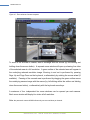
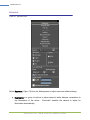
1
MegaXideo Cameras and AV Video System Software USER MANUAL Rev 5.0.0 Aug 8, 2007 [email protected] AV100 SOFTWARE IS PROVIDED ON AS-IS BASIS. ARECONT VISION, LLC DISCLAIMS ALL WARRANTIES WITH REGARD TO THIS SOFTWARE, INCLUDING ALL IMPLIED WARRANTIES OF MERCHANTABILITY AND FITNESS. IN NO EVENT SHALL ARECONT VISION BE LIABLE FOR ANY SPECIAL, INDIRECT OR CONSEQUENTIAL DAMAGES OR ANY DAMAGES WHATSOEVER RESULTING FROM LOSS OF USE, DATA OR PROFITS, WHETHER IN AN ACTION OF CONTRACT, NEGLIGENCE OR OTHER TORTUOUS ACTION, ARISING OUT OF OR IN CONNECTION WITH THE USE OR PERFORMANCE OF THIS SOFTWARE. ii USER MANUAL Table of Contents Chapter 1. Introduction .............................................................. 1 Product Overview........................................................................................ 1 Product contents ......................................................................................... 2 System Requirements................................................................................. 2 Standard performance ................................................................................ 2 Network switch or router ............................................................................. 2 Recommended Accessories ....................................................................... 3 Introduction ................................................................................................. 4 Connectors ................................................................................................. 5 Power……………………… ......................................................................... 6 Housing and Mounting ................................................................................ 6 Network Cabling.......................................................................................... 6 Optics…………………………………………………………………………….. 7 Manual Lenses............................................................................................ 7 Using Manual Iris Lenses ............................................................................ 7 Auto-Iris Lenses .......................................................................................... 8 Using Auto-Iris Lenses ................................................................................ 8 Monitoring Iris Status with AV Video System .............................................. 8 Accessing AV Cameras .............................................................................. 8 Supported Network Services ...................................................................... 9 Chapter 2. Video Surveillance Software ................................... 10 Software installation .................................................................................. 10 Configure Firewall ..................................................................................... 10 AV Application Manager ........................................................................... 14 Camera Installer........................................................................................ 14 Basic Mode ............................................................................................... 15 Advanced Mode ........................................................................................ 16 Operating AV Video System AV100.......................................................... 19 Arecont Vision, LLC 2400 N. Lincoln Ave., Altadena, CA 91001 iii USER MANUAL Toolbar…………………………………………………………………….. ....... 20 Selecting Full / Reduced Resolution and Zoom ........................................ 21 Settings…………………………………………………………………............ 23 Exposure………………………………………………………………………...24 Single Capture .......................................................................................... 26 Image Quality ............................................................................................ 28 Archive…………………. ............................................................................ 29 Motion Detection ....................................................................................... 30 Save to……………………. ........................................................................ 32 Advanced .................................................................................................. 32 Authentication ........................................................................................... 34 Remote Viewing ........................................................................................ 35 Day/Night .................................................................................................. 37 Auto-Iris………………………………………………………………………… 37 Right-Click Menu....................................................................................... 39 Language Selection .................................................................................. 41 Browsing Archives .................................................................................... 42 AVI Maker - Making video clips from the archive ...................................... 43 Firmware Loader - Upgrading the Cameras .............................................. 45 Chapter 3. HTTP Access ......................................................... 47 Non-Panoramic Cameras ......................................................................... 47 Camera Web Page ................................................................................... 47 HTTP JPEG Image Request Format......................................................... 48 HTTP MJPEG Image Stream Request Format ......................................... 49 Basic Camera Control Parameters ........................................................... 51 Parameters Specific to AV3130 DAY/NIGHT Cameras ............................ 53 Motion Detection Control Parameters ....................................................... 55 Access Control .......................................................................................... 57 HTTP/1.1 vs. HTTP/1.0 ............................................................................. 59 Arecont Vision, LLC 2400 N. Lincoln Ave., Altadena, CA 91001 iv USER MANUAL HTTP Access of Panoramic Cameras ...................................................... 60 Requesting Images from Camera ............................................................. 61 Getting and Setting Camera Parameters .................................................. 63 Access Control .......................................................................................... 68 Motion Detection ....................................................................................... 69 Chapter 4. Troubleshooting and Useful Tips ........................... 70 Connecting Directly To Laptop or PC........................................................ 70 Switches and Routers ............................................................................... 70 Low Sharpness ......................................................................................... 70 Frequently Asked Questions ..................................................................... 71 Chapter 5. Regulatory Compliance .......................................... 83 FCC Compliance Statement ..................................................................... 83 Terms and Conditions of Sale ................................................................... 83 Arecont Vision, LLC 2400 N. Lincoln Ave., Altadena, CA 91001 1 USER MANUAL Chapter 1. Introduction Product Overview AV100 supports full-motion real-time multi-camera viewing and policy-based archiving, remote access to live and archived video via Internet Explorer, post-event zooming from digital archives, simultaneous viewing of full-field of view and multiple zoomed images and a multitude of other features that take advantage of unique functionality and performance of Arecont Vision cameras. To complement its line of megapixel cameras, Arecont Vision offers full-featured video surveillance software, AV100. A typical system consists of a number of cameras connected over the local or wide area network to server PC running AV100 software. To achieve full motion archival rate, the server may be placed locally to the cameras so that the interconnecting LAN has sufficient bandwidth and small roundtrip delay between cameras and the server PC. A remote PC can connect to the server PC over a slower network connection, such as Internet. Once connected, the remote PC can display live video stream and browse archives using Internet Explorer. Note that when connected to AV100 software, the remote PC does not connect to cameras directly, but rather to the server PC on which AV100 is running. Figure1. Typical System Configuration LAN Internet Server Running AV Video System Arecont Vision, LLC 2400 N. Lincoln Ave., Altadena, CA 91001 2 USER MANUAL Product contents The AV MegaVideo Camera system consists of the following: Arecont Vision camera CD with NVR software Inspect the package and contents for visible damage. If any components are damaged or missing, do not use the unit; contact the supplier immediately. If you need to return the unit, you must ship it in the original box. System Requirements We recommend a dedicated PC to receive the image streams from cameras for archiving and display. The suggested minimum computer requirements are detailed for standard and high performance installations. Standard performance 24FPS at full resolution for AV2100: CPU: Core 2 Duo 2Ghz RAM: 1 GB Video Card: NVIDIA, 128 MB RAM Network card: 100 base-T, 2 network cards – one for cameras and one for remote viewing A PC with single, slower CPU is sufficient in the case when images are to be archived, but not displayed. HDD size according to the desired capacity of the video archives (approximately 200Kbytes/image). As an example, two 400GB drives will yield approximately 6 days of archiving capacity for an 8-camera system recording at 1 frame per second. Network switch or router Using a 100 Mbps network switch or router is recommended. Simple hubs do not provide collision management and are not suitable for multi-camera AV system. Suggested models: Arecont Vision, LLC 2400 N. Lincoln Ave., Altadena, CA 91001 3 USER MANUAL Power-over-Ethernet routers: Netgear ProSafe 8PT 100Base-TX Switch with PoE #FS108PNA, 10/100Base-TX w/4 PoE 100Base-TX, Street Price $110 ( www.netgear.com ). Netgear ProSafe 24+2 Gigabit Switch with POE, 1 Gigabit output w/12 PoE, 100Base-TX, Street Price$380 ( www.netgear.com ) D-Link Web Smart #DES-1316 (POE Switch/Hub)10/100Base-TX, 8 PoE ports and 8 non-PoE ports,True IEEE 802.3af,Street price $388 ( www.compuplus.com ) TRENDnet #TPE-S88 (POE Switch/Hub) www.trendnet.com 10/100Base-TX 8 PoE ports and 8 non-PoE ports, True IEEE 802.3af, Street price $250( www.provantage.com ) PowerDsine #PD-6001/AC (PoE Single port hub) www.powerdsine.com 10/100Base-TX, Single Midspan POE port, True IEEE 802.3af, Street price $29(www.provantage.com ) PoE network equipment must be CE marked for use in European Community. Note that the cameras are designed for use with indoor network cabling only. Recommended Accessories We recommend the following accessories: Monitors: Dell UltraSharp 2405FPW 24-inch Wide Aspect Flat Panel LCD Monitor with Height Adjustable Stand (www.dell.com) Samsung’s 243T, 24 Inch LCD Display (www.samsung.com) AV3130 requires a 3” window; all other cameras can use most any outdoor housing. Arecont Vision, LLC 2400 N. Lincoln Ave., Altadena, CA 91001 4 USER MANUAL Camera Reference Introduction AV1300, AV2100, AV3100, AV3130, AV5100, AV8180 and AV8360 are mega-pixel resolution IP cameras capable of delivering crisp, low-noise images at video frame rate. AV1300 is a 1.3-megapixel resolution camera having a maximum resolution of 1280 by 1024 and achieving a maximum frame rate of 30. AV2100 is a 2-megapixel resolution camera having maximum resolution of 1600 by 1200 and achieving a maximum frame rate of 24. AV3100 is a 3-megapixel resolution camera. Its maximum resolution is 2048 by 1536. AV3100 is typically viewed at 1920 by 1200 resolution with the frame rate up to 20. AV3130 is a dual-sensor, day-night camera featuring a 3-megapixel color sensor paired with a 1.3-megapixel monochrome sensor sensitive to near infrared illumination. When the scene is well-illuminated the 3-megapixel sensor is selected to deliver color images of up to 2048x1536 pixels. To provide seamless transition between day and night modes the color sensor is set to default resolution of 1920x1200 pixels. In low-light conditions AV3130 can automatically switch to the 1.3-megapixel (1280x1024) monochrome sensor, enabling the delivery of clear imagery at illumination levels as low as 0.01 lux. AV3130 typically delivers 20 FPS in day mode and over 30 FPS in night mode. AV5100 is a 5-megapixel resolution camera. Its maximum resolution is 2592 by 1944. AV5100 is typically viewed at 2560 by 1600 resolution with the frame rate up to 15. AV8180 is a quad-sensor 8-megapixel camera consisting of four 2-megapixel sensors and operating at up to 22 FPS per channel. It is capable to provide 180 degree field of view. Arecont Vision, LLC 2400 N. Lincoln Ave., Altadena, CA 91001 5 USER MANUAL AV8360 is a quad-sensor 8-megapixel panoramic camera consisting of four 2megapixel sensors and operating at up to 22 FPS per channel. It is capable to provide 360 degree field of view. All cameras are equipped with LAN connector and can deliver image data at a maximum data rate of up to 55 Mbps. Images are sent over the network in a compressed Motion JPEG format using TFTP protocol. All cameras feature: Automatic exposure (AE) and Gain (AGC) control Automatic backlight compensation Automatic multi-matrix white balance 50/60Hz selectable flicker control Electronic Zoom, Pan and Tilt (PTZ) Programmable brightness, saturation, gamma, sharpness, windowing and decimation Simultaneous delivery of full-field view and zoomed images at video frame rate Electronic image rotation by 180 degrees On board motion detection (except AV8180/AV8360: subject to change) Optional auto iris Connectors All AV cameras have the following connectors located on the rear panel of the camera housing: LAN connector, accepting a network UTP or STP cable carrying 100 Base-T. The LAN connector also accepts Power-over-Ethernet (PoE) Power terminals, accepting 12V-48V DC supply Optionally, a DC auto-iris connector. AV3130 does not support auto-iris and does not have this connector Arecont Vision, LLC 2400 N. Lincoln Ave., Altadena, CA 91001 6 USER MANUAL Power Power for all AV cameras can be supplied as follows: Via DC jack, 12V-48V. For power ratings see below. The center contact in the power connector is positive. Via LAN connector, 48V DC over spare wires or over data pairs. The cameras are compliant with IEEE 802.saf. The polarity is arbitrary. For a list of recommended PoE switches. (See “Network Switch or Router” on page 4) Power consumption will vary depending on the mode of operation. The maximum power consumption takes place when the camera is polled at full frame rate and runs at full resolution. The maximum power consumption is 4 Watts for AV1300, AV2100, AV3100; 4.5 Watts for AV3130; 5 Watts for AV5100; 6 Watts for AV8360; and 8 Watts for AV8180. Housing and Mounting All AV camera models feature a durable aluminum housing that minimizes fire hazards. The housing is not hermetically sealed. The ambient temperature should be maintained between 0ºC and 50ºC. The cameras are not to be used outdoors without appropriate protective enclosures. Cameras are mounted using a ¼” x 20 threaded hole at the bottom of the housing. When mounting the camera make sure the screw that goes into the hole is short, ¼” or less, and does not touch the camera board. The cameras are to be installed according to the applicable code. The mounting means should be adequate for mounting a 1 lb camera (except AV8360 that weights 4lbs) Network Cabling Category 5e cabling or better is recommended. All network cabling must be installed according to applicable codes and regulations. Arecont Vision, LLC 2400 N. Lincoln Ave., Altadena, CA 91001 7 USER MANUAL Optics All AV cameras should be used with a 1/2” or 2/3” optical format lenses. AV3130 requires two manual iris lenses and has a limitation on lens diameter (<38mm). AV8360 is supplied with 4 preinstalled high-quality lenses. Manual Lenses A wide variety of C/CS mount lenses with mega-pixel resolution may be used with AV cameras. Note that all C-mount lenses require a 5mm adaptor ring. Some lenses may also require 0.4mm-0.8mm adjustment spacers. Arecont Vision lens suggestions include: Arecont LENS4-10 (4mm -10mm). Computar H0514-MP (5mm), M0814-MP (8mm), M1214-MP (12mm), M1614-MP (16mm), M2514-MP (25mm), M5018-MP (50mm), HG2Z0414FC-MP (4mm - 8mm), M3Z1228C-MP (12mm - 36mm). Fujinon HF12.5SA-1 (12.5mm), Fujinon HF16SA-1 (16mm), Fujinon HF25SA-1 (25mm), HF35SA-1 (35mm), Fujinon HF50SA-1 (50mm), Fujinon HF75SA-1 (75mm). Fujinon DF6HA-1B (6mm), HF9HA-1B (9mm), HF12.5HA-1B (12.5mm), HF16HA-1B (16mm), HF25HA-1B (25mm), HF35HA-1B (35mm), HF50HA-1B (50mm), HF75HA1B (75mm). Tamron 12VM1040ASI (10mm - 40mm). Using Manual Iris Lenses Choosing the lens correctly is very important for mega-pixel cameras. Poorly selected lenses may cause the image to appear blurry when the lens iris is fully open or closed too much. To deliver sharp mega-pixel resolution images, it is recommended to: Use mega-pixel-resolution lenses. Obtain best resolution and depth of focus by having the iris slightly closed. When setting up the camera, direct the camera at the scene and try closing the iris by several F-stops. At some point the image will look it’s sharpest. Leave the iris closed at this value. Arecont Vision, LLC 2400 N. Lincoln Ave., Altadena, CA 91001 8 USER MANUAL Auto-Iris Lenses Standard DC auto-iris lenses could be used with AV1300, AV2100 and AV3100 cameras equipped with the auto-iris feature. Arecont Vision recommends the following high- resolution optics: Computar HG2Z0414FC-MP 4mm-8mm Tamron 12VM412ASIR-SQ 4mm-12mm Tamron 12VG1040ASIR-SQ 10mm-40mm Using Auto-Iris Lenses AV1300, AV2100 and AV3100 are available with DC auto-iris option. To use the DC autoiris lens: 1) Attach the lens to the AV camera. 2) Plug in the lens cable into the connector on the back of the camera. Make sure that the lens cable is long enough. Many DC lenses are available with short and long cable options. The camera will automatically detect the presence of an auto-iris DC lens and start using it. Auto-iris lens operation typically proceeds as follows: If illumination is sufficient, the camera will close the iris within half-a-minute. When the iris is closed, the image should become visibly sharper. As the iris is gradually closed the image brightness may fluctuate slightly. Monitoring Iris Status with AV Video System You can monitor the state of the iris in AV Video System “Settings” dialog. See “Operating AV Video System” for details. Accessing AV Cameras Cameras can be accessed and controlled by means of AV Video System software (AV100) User software utilizing Arecont Vision camera SDK (Software Developer Kit) HTTP requests issued from IE Explorer or other applications Arecont Vision, LLC 2400 N. Lincoln Ave., Altadena, CA 91001 9 USER MANUAL Supported Network Services All AV cameras, namely AV1300, AV2100, AV3100, AV3130, AV5100, AV8180 and AV8360, support TFTP and HTTP network protocols. TFTP protocol yields the highest frame rate. It is accessible to the user through manufacturer SDK which supports both Windows and Linux platforms. Interested users can contact [email protected] to obtain access to the SDK. Current AV100 software is based on TFTP protocol. Future releases may add support for HTTP protocol as well. HTTP protocol delivers lower frame rates but allows direct access to the cameras through Internet Explorer or other HTTPbased application. Arecont Vision, LLC 2400 N. Lincoln Ave., Altadena, CA 91001 10 USER MANUAL Chapter 2. Video Surveillance Software Software installation To install AV100 software: 1. Make sure your Windows XP/Vista account has administrative privileges. 2. Open “Control Panel\Add or Remove Programs”, remove old versions of AV Video System software if any. 3. Run Setup.exe and follow the directions to complete the installation. 4. If using Windows Vista, users must navigate to installation directory, open “My Computer\C Drive\ProgramFile\ArecontVision\VideoSurveillance\LocalMachine (type choose Application). Right-click on this file named “LocalMachine.exe”, choose “properties -> Compatibility -> Privilege Level” and enable the “Run this program as an administrator” option. Setup process installs software and places a shortcut Arecont Vision Application Manager on the desktop and creates a group Arecont Vision\AV Video System in the Start menu. Configure Firewall As you start AV applications, your PC may prompt you to permit access to the network. AV Video System includes two applications that need access to the network: AVInstaller.exe: the camera finding and installation program LocalMachine.exe: the viewing and archiving program Both executables are located in the AV installation folder. You should grant access to these two applications when the firewall prompts you. For example: Arecont Vision, LLC 2400 N. Lincoln Ave., Altadena, CA 91001 11 USER MANUAL For older version of Norton Internet Security (Figure 2), select Permit Always and click Ok. Figure 2. Older version of Norton Internet Security For newer version of Norton Internet Security ( Figure 3), go to Settings->Personal Firewall (under Web Browsing) and select Turn Off. Figure 3. Newer version of Norton Internet Security Arecont Vision, LLC 2400 N. Lincoln Ave., Altadena, CA 91001 12 USER MANUAL For McAfee Personal Firewall (Figure 4), click Grant Access. Figure 4. McAfee Personal Firewall Plus If you are using Windows XP firewall, follow these instructions: 1. Click the Windows Start button and select Control Panel>Windows firewall. 2. Windows Firewall settings dialog will appear. If the firewall is on, make sure Don’t allow exceptions is unchecked (Figure 5). Figure 5. Windows Firewall General Tab Arecont Vision, LLC 2400 N. Lincoln Ave., Altadena, CA 91001 13 USER MANUAL 3. Click “Exceptions” tab. Make sure “AV Manager”, “AV Video System” and “AV Installer” appear in the list of programs and services and have a checkmark next to them (Figure 6). If these applications are not in the list, click Add Program button. Figure 6. ExceptionsTab 4. Find “AV Installer” in the list of programs and click Ok. Repeat same for “AV Video System”. Figure 7. Add a program 5. Click Ok to close the Windows Firewall dialog. Arecont Vision, LLC 2400 N. Lincoln Ave., Altadena, CA 91001 14 USER MANUAL AV Application Manager Setup.exe places the shortcut to the AV Application Managers on the user’s Desktop. All programs and utilities comprising AV Video System can be accessed via AV Application Manager. The standard selections include Camera Installer, Video System, and AVI Maker. The Firmware Loader can also be listed as shown below (figure 8) if the AVFirmwareLoader.exe is placed in “Arecont Vision\Video Surveillance” folder. Figure 8. Application manager The AV Application Manager standard selections include: Camera Installer. Setup cameras (see Camera Installer on page17) Video System. Watch live video (see Operating AV Video System on page18) AVI Maker. Make video clips from archive (see AVI Maker on page...) Firmware Loader. Upgrade cameras (see Upgrading the cameras on page...) Camera Installer Camera Installer allows to find all AV cameras that are present on the local area network, assign IP addresses to detected cameras and to verify that the cameras are accessible and operational. Camera Installer saves information about installed cameras into an .ini file Arecont Vision, LLC 2400 N. Lincoln Ave., Altadena, CA 91001 15 USER MANUAL used by AV Video System. Camera Installer supports two modes of operation – Basic and Advanced. Basic Mode In this mode Camera Installer detects all AV cameras that can be reached by the broadcast request and automatically assigns IP addresses to the cameras, selecting those addresses that belong to the same sub-network as the computer running Camera Installer and that are not assigned to other devices. To detect and install the cameras automatically the user should simply press Install Cameras button. The installer will find, configure and verify the operability of the cameras and report installation results as shown below (figure 9). Users can sort the available cameras by MAC address or IP address, in ascendant or descendent order, by clicking on the appropriate title. Once the installation is completed, users should press Save/Exit button to save the installation information into a file LocalMachine.ini and export a plaintext list of cameras into a file CameraList.txt Figure 9. Basic mode Arecont Vision, LLC 2400 N. Lincoln Ave., Altadena, CA 91001 16 USER MANUAL Advanced Mode In this mode the user can detect all AV cameras present on the local area network and choose one or more cameras to install. The installer has a mechanism to protect previously installed cameras (if any) from accidental changed. It also allows users to set IP address of the cameras either automatically (as in Basic mode) or manually when specific range of IP addresses is required. Sorting feature is the same with that in Basic mode. (Figure 10) Figure 10. Advanced mode Advanced mode has an Advanced Features function group which is usually invisible. Users can click Show Advanced Features to make it visible and click again to hide it. The “Advanced” mode provides the following set-up functions: Find Cameras – this function searches for all AV cameras that are present on the local network and are accessible by the broadcast request. As a mechanism to protect any previously installed cameras from accidental change, Arecont Vision, LLC it will also attempt to find 2400 N. Lincoln Ave., Altadena, CA 91001 cameras from 17 USER MANUAL “LocalMachine.ini” and set the default status of those cameras to “Installed, locked” so that further operations will not affect those cameras. At the completion of this operation the Installer will show all detected cameras. TIP: Users are able to lock/unlock any previously installed cameras using the functions in the Advanced Features group. This group is hidden by default, but users can click Show Advanced Features to make advanced features visible. Install Selected – this function installs the selected cameras and verifies their operatability in a way similar to the Install Cameras function in Basic mode. When one or more camera are selected (highlighted), the selected cameras will be installed and the unselected ones will be skipped. When no cameras are selected (highlighted), the Installer will install all cameras available. TIP: All cameras marked as “Installed, locked” will be skipped in order to protect previous installations from accidental change. To change the status of those cameras, please refer to the Find Cameras section. Unselect All – Deselect all cameras. View Selected – Open a web-browser to view the selected camera’s HTTP interface where users can watch the live video and configure the camera. TIP: Double-click the selected camera in “Result” or “Model/Version” section has the same effect. Edit Selected – Open an Advanced dialog to edit the selected camera’s IP address and/or add a camera specific description to the selected camera. Arecont Vision, LLC 2400 N. Lincoln Ave., Altadena, CA 91001 18 USER MANUAL TIP: Double-click the selected camera in IP address or Description section has the same effect. Add Remote Units – Open an Advanced dialog to add a camera manually. This feature is designed for application scenarios where the camera to be installed is on another sub-net that is not reachable by broadcasting. Users should use this feature only if the camera’s MAC and IP addresses are known and the connectivity has been verified. Save/ Exit – Save the information of the installed cameras into a file “LocalMachine.ini” for AV Video System and export a plaintext list of cameras into a file “CameraList.txt” for third party software, then exit the Installer. Arecont Vision, LLC 2400 N. Lincoln Ave., Altadena, CA 91001 19 USER MANUAL Operating AV Video System AV100 Note: AV Video System requires a license file for each of the installed AV cameras. The license is tied to a unique camera’s MAC address. The license files are located in the C:\Program Files\Arecont Vision\Video Surveillance\license folder. However, for the evaluation purposes, AV100 will operate any one AV camera without a license. After the cameras are successfully installed, the AV Video System can be activated by clicking on the corresponding Run button in the AV Application Manager. The Arecont Vision welcome screen will appear and hide automatically. The AV Video System software will start on its own after a few seconds. Shown below (Figure 11) is the AV Video System displaying live video from sixteen AV cameras. If Hide is selected, the application will be placed onto the system tray of the Windows task bar. Figure 11. Live video display Arecont Vision, LLC 2400 N. Lincoln Ave., Altadena, CA 91001 20 USER MANUAL Toolbar The toolbar of the AV Video System is located in the upper portion of the screen above the video display area. It contains the following icons: Turns on/off a drop-down list of the installed cameras. Individual cameras are disabled / enabled by left double-clicking on the camera number. When disabled, live video image from the disabled camera is replaced with a blue rectangle, and the camera number in the drop-down list is marked with a red cross. Displays the Settings menu (see Setting below). Enables a full screen display without the toolbar and menus. Selects screen layout for viewing live/archived video from multiple cameras (from left to right): single camera layout, 2x2 camera layout; 3x3 camera layout; 4x4 camera layout; 10-camera layout with 2 large and 4x2 smaller images; 8-camera layout with 1 large, 3x1 and 1x4 smaller images; 13-camera layout with 1 large, 2x2 and 4x2 smaller images, 8-camera layout with 2x4 images for panoramic cameras, 10-camera layout with 2 large and 2x4 smaller images for regular and panoramic cameras. Depending on the chosen screen layout and the actual number of the installed cameras, the unused sections of the layout will be filled with a watermark image of the Arecont Vision camera. Displays the Archive controls (see Browsing Archives below). Arecont Vision, LLC 2400 N. Lincoln Ave., Altadena, CA 91001 21 USER MANUAL Takes a snapshot of live video or an archive. The snapshot is taken from the camera which is highlighted in the drop-down list of the installed cameras (see above). To highlight another camera, left-click on the camera number. To take the snapshot from all cameras, highlight “cameras” at the root (top) of the dropdown camera list. The snapshot file names contain the camera number, date and time of the snapshot. To locate/view the snapshots in the snapshot folder, rightclick anywhere on screen, then select “photo”, “browse”. Alternatively, snapshots can be taken by right-clicking on the live video image, and then selecting “photo”, “save”. The directory path to the snapshot folder is specified in the Settings menu (see Settings), or using the Right-Click menu under “Save To” (see Right-Click menu). By default, this is the directory C:/Program Files/Arecont Vision/Video Surveillance/photo. Reports the current CPU usage and network usage. The first two LED bars show the CPU usage and total network usage in per cent, respectively. The rest of LED bars show the network usage of each camera. The shown values are relatively to the camera which uses the most bandwidth. Selecting Full / Reduced Resolution and Zoom In order to fit multiple video images on screen the images are displayed at a reduced resolution. The format of the reduced resolution display is determined by the chosen screen layout (see Toolbar above on page 22). An individual camera image can be expanded to a full resolution display by left doubleclicking on the image. The full resolution image can be scaled back to its reduced resolution display by left double-clicking on the image. Image resolution (in pixels) is displayed in the upper left corner of the image. An alternative mode of viewing the high resolution content is the zoom window (see screen snapshot below, figure 12). Arecont Vision, LLC 2400 N. Lincoln Ave., Altadena, CA 91001 22 USER MANUAL Figure 12. Zoom window of screen snapshot To zoom-in on an area of interest, draw a rectangle with the mouse (by left-clicking and holding down the mouse button). A separate zoom window will open up showing live video of the selected area at a full resolution. A green outline of the selected area will appear in the underlying reduced resolution image. Zooming in and out is performed by pressing Page Up and Page Down on the keyboard, or alternatively by rotating the mouse wheel (if available). Panning of the zoomed area is performed by dragging the green outline across the underlying camera image with the mouse (by left-clicking within the outline and holding down the mouse button), or alternatively with the keyboard arrow keys. A maximum of four independent live zoom windows can be opened per each camera. Each zoom window will display live video at full resolution. Note: the panoramic camera AV8360 allows only one zoom window per channel. Arecont Vision, LLC 2400 N. Lincoln Ave., Altadena, CA 91001 23 USER MANUAL Settings Settings menu (Figure 13) is displayed by clicking on the Settings button in the toolbar. Figure 13. Setting menu Settings menu is the top level menu for all settings provided in the AV Video System. Selecting one of the menu items opens up a lower level drop-down menu containing detailed settings and options. Depending on the camera model, some of the listed groups of settings may become unavailable (for example, Day/Night settings are available only for the AV3130 camera). Note: selecting “Reset all” restores default settings of all available cameras. The lower level menus contain a “Camera” field that displays the camera number which the settings are applied to (Figure 14). The “Camera” field can be expanded to a drop-down list of all installed cameras to select from. The list includes an “All cameras” option to apply settings to all cameras. Figure 14. Display the camera number Arecont Vision, LLC 2400 N. Lincoln Ave., Altadena, CA 91001 24 USER MANUAL Exposure Figure 15. Exposure menu Select Exposure (Figure 15) from the Setting menu to adjust exposure related settings: Illumination is a group of options to adjust camera’s white balance computation to the illumination of the scene. “Automatic” enables the camera to adjust for illumination automatically. Arecont Vision, LLC 2400 N. Lincoln Ave., Altadena, CA 91001 25 USER MANUAL Lighting is a group of options to adjust camera’s auto exposure computation to the oscillation frequency of the indoor lighting: European (50 Hz) or US/Japan (60 Hz). Low Light Mode is a group of options to adjust camera’s operation under low light conditions: a. High Speed enables the shortest exposure time, selectable from a drop-down list “Short Exposure” between 1 and 10 ms, and the maximum frame rate. This option will reduce motion blur, but may result in a noisier video due to a high gain under low light conditions. b. Speed enables short exposure time not exceeding 10 ms by raising video gain as much as possible unless the low light conditions require a further time increase (up to 80 ms). c. Balanced enables medium-duration exposures up to 20 ms by raising video gain as much as possible unless the low light conditions require a further time increase (up to 80 ms). d. Quality enables longer exposures up to 40 ms, by raising video gain as much as possible unless the low light conditions require a further time increase (up to 200 ms). Motion blur may become high, but video will contain less noise under low light conditions. e. Moon Light enables very long exposures up to 500 ms if necessary. Auto exposure On/Off is an option to enable/disable the on-camera automatic exposure computation. Auto exposure maintains the target image brightness under changing lighting conditions. Single Capture – please go to the “Single Capture” section of this manual. (page 29) Arecont Vision, LLC 2400 N. Lincoln Ave., Altadena, CA 91001 26 USER MANUAL Single Capture Single Capture is a newly introduced work mode available on AV cameras of model AV1300, AV2100, AV3100, AV5100. This work mode is designed for application scenarios where a single image is to be captured when an external event triggers the camera’s auxiliary input. Possible application areas include license plate capturing, door control systems, photo booths, etc. When single capture is activated, the camera stops sending live video and enters an endless loop to check external trigger events. The software that communicates with the camera must send image requests constantly and check whether the response from the camera contains image. When there is no event, the camera responds to image requests with an empty data packet. When an event occurs, the camera responds to the most recent image request with the captured image. Single capture function is primarily designed for low-light applications where an external flash is needed. When there is enough light, the camera automatically switches to a regular High Speed mode with short exposure time, about 1 ~ 2 ms, without triggering the flash. To use the single capture function properly, the camera must be physically connected to an external trigger source (as input) and a flash (as output). Then the camera should go through a calibration process to setup a working environment. In AV100 software, under “Exposure \ Single Capture” function group, there is a button “Calibrate Flash” to initiate the calibration. The calibration process takes about 13 seconds, during which period the flash will be triggered 13 times. Once the calibration is done, users should check the result of calibration by clicking the “Check Calibration” button. On clicking the button, the software reports an integer resulting from the calibration. If the number is within 768 ~ 6144, the calibration is successful, otherwise the calibration fails. For better image quality, one would expect the number to fall within 2000~3000 range. This number is under influence of the status of the iris. Closing the iris will cause the number to increase, and vice versa. Users Arecont Vision, LLC 2400 N. Lincoln Ave., Altadena, CA 91001 27 USER MANUAL may go through the calibration->adjusting iris->recalibration cycle for several times until the calibration result is satisfactory. Once the calibration is done, the camera is ready to handle trigger events. During normal operation, there will be no live video displayed. In case of trigger events, AV100 software receives the captured images and stores it in the “photo” folder. On the menu there is a checkmark “Add timestamp to photos”. When it is checked, the stored images will be marked with timestamp and user information. When AV100 software restarts, it automatically searches the “photo” folder for a file named “userinfo.txt” which stores user defined information for a specific camera. Users can edit this file so that user-specific information can be added to the captured images. Arecont Vision, LLC 2400 N. Lincoln Ave., Altadena, CA 91001 28 USER MANUAL Image Quality Figure 16. Image Quality menu Select Image Quality from the Setting menu. Image Quality is a lower-level menu to adjust image quality settings: Compression adjusts the level of JPEG compression applied to the images in different display modes: “Full View” is to display full resolution video. “Multi View” is to display multiple cameras at a reduced resolution. “Zoom View” is to display zoom windows. Brightness adjusts image brightness. Sharpness adjusts image sharpness. Saturation adjusts image color saturation. Red adjusts the red tint. target for computation. camera’s This setting changes the automatic white balance The effect is gradual: it takes 20-30 seconds for the camera to fully adjust to the new setting. Blue adjusts the blue tint. This setting changes the target for computation. camera’s automatic white balance The effect is gradual: it takes 20-30 seconds for the camera to fully adjust to the new setting. Speed adjusts the rate at which the computer requests images from the camera. The maximum rate is limited by the camera, (different for different camera models). Size of Picture adjusts starting coordinates and the image size. Note: affected by “Don’t update sensor window” in Advanced settings. Rotate 180 is an option for flipping the image vertically and horizontally such that it is rotated 180 degrees. Arecont Vision, LLC 2400 N. Lincoln Ave., Altadena, CA 91001 29 USER MANUAL Archive Select Archive (Figure 17) from the Setting menu. Archive is a lower-level menu to set up video archival settings: Figure 17. Archive menu Filter is a group of archiving options: Save all frames enables archiving the entire video stream received from the camera. Save all and mark motion enables saving the entire video stream and marking the frames when motion was detected for future archive browsing. Save only motion enables archiving only when motion was detected by the oncamera motion detector, and disables it in the absence of motion after a period of time specified under Continue after motion detected. Frequency is a drop-down list of options for archive recording rate. The “Off” option disables the archive recording. The “Max” option sets the archive frequency limited only by the camera and the network (different for different camera models). Continue after motion detected is a drop-down list of options for the duration of archiving after the motion was last detected by the on-camera motion detector, and the frame rate at which such recording is done. Note: if new motion is detected during such after-motion recording, the rate of recording will revert to the one specified under “Frequency”. Arecont Vision, LLC 2400 N. Lincoln Ave., Altadena, CA 91001 30 USER MANUAL Motion Detection Motion detection is achieved by analyzing inter-frame brightness changes on a pixel-bypixel basis. There are two modes of Motion Detection supported in AV Video System: a software mode and an on-camera mode. The software mode performs motion detection by processing the images after they were transmitted from the camera to the computer. In contrast, the on-camera mode performs motion detection prior to transmitting the images to the computer. Thus, the on-camera motion detection allows to significantly reducing the CPU load and the network load when motion detection is enabled. Motion detection is enabled via the Archive settings when one of the two following options is selected: “Save all and mark motion” or “Save only motion”. If the Archive is enabled for “Save all frames” motion detection is disabled. The Enabled/Disabled status is displayed in the bottom right corner of the Motion Settings window. Motion detection is computed independently in multiple detection zones on a square grid. The largest grid supported for any AV camera model and image size is 8 by 8. The actual grid for any particular model is determined by the chosen zone size (a drop-down list in the lower right corner of the Motion Settings screen) and the camera’s pixel resolution. The actual grid is displayed in the lower left corner. When motion is present, the Motion Settings window displays green marks (selectable between crosses and boxes) in the zones affected. (Figure 18) A privacy mask can be set up to block motion detection in some of the zones by drawing a rectangle with the mouse (by left-clicking and holding down the mouse button). The privacy mask is marked with red crosses. A more complex shape can be created by drawing multiple rectangles. Erasing the mask (or part of the mask) is done by drawing a rectangle with the right mouse button. Arecont Vision, LLC 2400 N. Lincoln Ave., Altadena, CA 91001 31 USER MANUAL Figure 18. Image of motion detection Motion detection settings apply only to the camera which number is displayed in the Camera field on the left of the Motion Settings menu: use drop-down list to change the camera number. The settings are: Detected by provides two options to select between the software motion detection and the on-camera motion detection. Note: some of the AV camera models may not support motion detection on-camera. Sensitivity is a group of controls to adjust motion detection computation: Level adjusts the inter-frame brightness change threshold that triggers motion detection. Lower settings may cause false motion detection due to noise. Detail adjusts the size of the detectable objects within each motion detection zone. Lower settings may cause false motion detection due to noise. Limit serves as a guard against false triggering due to a sudden overall change in lighting that would trigger motion detection in a large number of zones simultaneously. If the number of zones activated simultaneously is larger than “Limit”, motion detection will be blocked. This parameter cannot exceed the number of zones in the grid (displayed in the lower left corner of Motion Settings). Arecont Vision, LLC 2400 N. Lincoln Ave., Altadena, CA 91001 32 USER MANUAL Save to A lower level Save to menu allows to specify the directory path for video archives and for snapshot images. Note that the name of archival directory should be the same for all cameras; it is possible to specify different Hard Drives for each camera. Advanced Select Advanced from the Setting menu (figure 19) to set the following options: Figure 19. Advanced menu Arecont Vision, LLC 2400 N. Lincoln Ave., Altadena, CA 91001 33 USER MANUAL Don’t update sensor window is an option that determines how the changes to the image size are applied: at a software level or in hardware (the image sensor). Enabling this option helps to avoid conflicts when multiple users are viewing the same camera (each will be able to set different image size). Alternatively, disabling this option allows to increase the camera frame rate due to a smaller image size. Use DirectX if possible is an option to use DirectX functions that utilize graphics card hardware to display images instead of using the software. This reduces the load on the CPU. The drop-down list “DirectX size” provides options for the graphics area size supported by DirectX. Auto – Startup is an option to automatically restart the AV Video System with the earlier settings after it was stopped. RealTime if folded is an option to continue running the AV Video System application at the top priority level in the Windows Task Manager after the application was minimized and placed onto the system tray of the Windows task bar. Show motion is an option to mark the areas of the image where motion was detected. Use double packets is an option to use data packets with 2904 bytes instead of the regular 1450 bytes for image transmission. This allows to increase image transmission bandwidth, but may lead to a less stable performance on overloaded networks. Warning on disconnect is an option to display a red screen warning in place of live video that has been disconnected or temporarily lost. An alternative (when disabled) is to display the last captured frame. Static ARP is an option to enable a static link between the camera’s MAC address and its IP address. An alternative is a dynamic ARP that is not supported by some of the older models of the AV cameras. Arecont Vision, LLC 2400 N. Lincoln Ave., Altadena, CA 91001 34 USER MANUAL Authentication Authentication is used to set up password-protected access to AV Video System. For any users there are three levels of access available ( Figure 20): Figure 20. Authentication menu “Administrator” grants full access to all features of AV Video System. “Viewer” grants access to live video and browsing the archives, but not to the settings. “Live only” grants access to live video only. Adding, changing, and removing the users is done via three buttons Add, Change, and Remove on the bottom of the menu. Arecont Vision, LLC 2400 N. Lincoln Ave., Altadena, CA 91001 35 USER MANUAL If one or more user accounts were created, the AV Video System will display a log-in dialog prompting for the user name and password (Figure 21): Figure 21. User authentication Remote Viewing AV100 software has built-in web server allowing AV cameras and archives to be viewed remotely. (Figure 22) Figure 22. Remote viewing menu Arecont Vision, LLC 2400 N. Lincoln Ave., Altadena, CA 91001 36 USER MANUAL To enable the built – in HTTP server, select Remote viewing from the Setting menu and do the following: 1. Select Allow Remote Viewing. 2. On the bottom of the menu click Apply then Ok 3. Start Internet Explorer and type in the address of the web server. For example, if AV Video System is installed on a PC with IP address 200.168.1.102, type in the following address: http://200.168.1.102:4250/guix.htm 4. Then click Enter to have Internet Explorer open that page. 5. Upon successful connection a web page will open. Internet Explorer will prompt to install an ActiveX component. Click on the webpage as prompted to install ActiveX. 6. The main AV menu located on the left hand side of the IE window will provide full access to each AV camera. Selecting the AV camera of choice will display the option to disconnect as well as make changes to settings such as the Resolution, Speed, Archive, Zoom and viewing images in separate windows. 7. Right-clicking anywhere on the Explorer web page will provide access to the options menu: Click Save to take a snapshot image. Click Manage Servers provides server information and allows changes to the servers. Click Auto Hide Menu allows to automatically hiding the main menu. Click Settings to adjust camera and video settings. Arecont Vision, LLC 2400 N. Lincoln Ave., Altadena, CA 91001 37 USER MANUAL Day/Night Day/Night (Figure 23) settings apply only to AV3130 camera including: Figure 23. Day/Night setting menu Automatic enables the camera to automatically switch from daylight conditions (using the color sensor) to nighttime conditions (using the monochrome sensor), and back based on the Threshold settings. Day enables the daylight mode and disables the nighttime mode. Night enables the nighttime mode and disables the daylight mode. Threshold adjusts the automatic switching of the camera: Switch At adjusts the level of darkness to switch from daylight to nighttime mode. Toggle Guard adjusts the level of brightness to switch from nighttime to daylight mode. Toggle Guard set to 0% corresponds to “Switch At” set to 100%. Toggle Guard should be adjusted to prevent mode toggling during the transitional lighting. Auto-Iris The Auto-Iris menu allows monitoring the state of the automatic DC iris. If the scene is too dark, the camera will open the iris fully. This allows more light onto the sensor and will substantially improve the low-light performance. If the scene is too dark when the camera is started, the camera will not close the iris until there is enough illumination. Arecont Vision, LLC 2400 N. Lincoln Ave., Altadena, CA 91001 38 USER MANUAL Camera DC auto- iris can be configured using “Auto-Iris” menu (Figure 24): Figure 24. Auto-Iris menu The iris can be disabled by un-checking Enabled. The camera will open the iris fully and have electronic auto-exposure working. This configuration is identical to using a manual lens. The state of the auto-iris is displayed on a color panel which has six different states: Disabled: The auto-iris is either disabled by un-checking the Enabled check box, or is not present. Arecont Vision, LLC 2400 N. Lincoln Ave., Altadena, CA 91001 39 USER MANUAL Evaluating: The camera is preparing to close the iris. Too Dark. The camera cannot close the iris because the scene illumination is too low. Closing: The iris is closing down by the number of F-stops appropriate for the lens model. Closed: The iris is closed. Opening: The iris is opening. Auto-iris will open the lens fully once the on-camera analog gains exceed certain level. Gain scroll bar adjusts the point where the auto-iris will open fully: the higher the gain the later will the auto-iris open as the illumination diminish. Right-Click Menu Right-clicking anywhere within the AV Video System screen allows invoking an additional menu (Figure 25): Figure 25. Additional menu within AV Video System screen Arecont Vision, LLC 2400 N. Lincoln Ave., Altadena, CA 91001 40 USER MANUAL Show presents two options: Archive enables access to browsing archives (See Browsing Archives). Photos enables access to snapshots taken with the AV cameras. The default snapshots location is C:\Program Files\Arecont Vision\Video Surveillance\photo, a different directory path to the snapshot folder can be specified in the Settings menu (see Settings on page 26). Photo enables saving and printing individual snapshots, as well as browsing: Save takes a snapshot of live video and saves it in the snapshot folder. The snapshot is taken from the camera which is highlighted in the drop-down list of the installed cameras (see Toolbar on page 22). To highlight another camera, left-click on the camera number. To take the snapshot from all cameras, highlight “cameras” at the root (top) of the drop-down camera list. Save/Print takes a snapshot and prints it instantly. Browse opens the snapshot folder for browsing. Settings enables access to changing the main groups of settings as described in Settings (see Settings on page 26): Miscellaneous enables access to the following: Authentication (see Permission). Remote Viewing (see Remote Viewing on page 40). Save to (see Save to on page 36). Advanced (see Advanced on page 37). Camera enables access to a combined menu that includes: Image Quality (see Image Quality on page 31 ) Exposure (see Exposure on page 27 ) Day/Night (see Day/Night on page 42) Auto-Iris (see Auto-Iris on page 44 ) Archive (see Archive on page 33). It also includes some of the options in Advanced settings (see Advanced on page 37). Motion enables access to Motion Settings (see Motion detection on page 34). Arecont Vision, LLC 2400 N. Lincoln Ave., Altadena, CA 91001 41 USER MANUAL Printer opens up the Print Setup menu. Dump logs camera settings to a file named LocalMachine.ini located in the installation directory. When contacting Arecont Vision’s technical support, this file should be included. Video displays live video in full-screen mode. Hide minimizes the AV Video System application and hides it in the system tray of the Windows task bar. Log off logs off the current user. Exit exits the AV Video System application. About shows the version of the AV Video System software and the additional information for each of the installed camera(s): revision of firmware, MAC address, and IP address. Language Selection AV Live Video System supports interfaces in Arabic, Chinese Simplified, Chinese Traditional, English, Finnish, German, Japanese, Spanish, Russian and other languages. To select language press the F2 button to bring up the language menu (Figure 26). Figure 26. Language menu Arecont Vision, LLC 2400 N. Lincoln Ave., Altadena, CA 91001 42 USER MANUAL Browsing Archives Archive browsing is enabled by pressing the button in the Toolbar, or via the right- click menu (see Right-Click Menu on page 46). Figure 27. Archive screen Archive browsing controls are located on the bottom of the playback screen (Figure 27). Archives are best viewed when the video is displayed in full-screen mode. The date-andtime stamp is located on the top left-hand side of the image. The user can select playback speed and frame skipping, as well as the image quality. If the archive was recorded using motion detection (see Motion Detection), browsing can be based on detected motion by selecting “Motion” from the drop-down list under “Filter”. Rewind - Starts browsing from the start of recording Fast Reverse Play in Reverse – Plays the recorded archive continuously in reverse Play by Frame in Reverse – Starts the playback one frame at a time reverse Pause – Pauses the playback. Play by Frame Forward – Starts playback one frame at a time forward. Play – Plays the recorded archive continuously forward. Arecont Vision, LLC 2400 N. Lincoln Ave., Altadena, CA 91001 43 USER MANUAL Fast forward Forward - Starts browsing from the end of recording. The slider on the bottom of the screen displays/positions the current frame position in the archive. It has a date-and-time display located to the right side of the slider to reference a particular event. To take a snapshot from the archive use button from the Toolbar. Alternatively, snapshots can be taken by right-clicking on the video image, and then selecting “photo”, “save”. AVI Maker - Making video clips from the archive The AVI Maker (Figure 28) is started by clicking the corresponding Run button in the AV Application Manager. Figure 28. AVI Maker NOTE: PLEASE MAKE SURE THAT THE ARCHIVE IS NOT EMPTY WHEN MAKING AVI CLIPS. To make video from archive, please do the following steps: 1. Using the Camera drop-down list on the left select the camera archive for making the video clip from. Arecont Vision, LLC 2400 N. Lincoln Ave., Altadena, CA 91001 44 USER MANUAL 2. Using the DateTime is for setting the start and the end of the archived events to be converted into the AVI video clip. 3. Using the Video Settings provides three options: Size of Frame adjusts the AVI frame size relative to the archived frame size. Frame Period adjusts the AVI frame rate (in milliseconds). If this setting does not match the archived frame rate, the AVI video will be playing accordingly faster or slower. Video Compression offers three options for making the AVI file: “MSVC - standard” is a standard Microsoft video codec. “XviD – http://www.koepi.org/xvid.shtml” is a codec recommended by Arecont Vision (it is included in the AV Software Setup, and is typically installed during the AV software installation). This codec has been found to produce very good quality and compression of resulting AVI files. “Codec List” allows to select any of the alternative codecs that are installed on the computer. The drop-down list opens after “Make AVI” is clicked (Figure 29). Figure 29. Video Compression Arecont Vision, LLC 2400 N. Lincoln Ave., Altadena, CA 91001 45 USER MANUAL 4. Click Make AVI. If no records are available for the selected range of dates or times a warning will be displayed. 5. In the Save as window type in a file name for your new AVI file, then click Save. If “Codec List” was selected under “Video Compression” the drop-down list of available codecs will appear. Select a codec from the list to proceed. 6. The AVI Maker will begin to create the AVI and show the progress in the progress bar. Optionally, click Stop to terminate the process earlier than the end date/time set under DateTime. Firmware Loader - Upgrading the Cameras All models of AV cameras are field-upgradeable. AV Firmware Loader is the utility for upgrading the camera’s firmware and/or hardware. Note: all AV cameras starting with firmware revision 51821 support firmware upgrades, and all AV cameras with MAC address ending with 62-00 and above also support hardware upgrades. NOTE: IT IS RECOMMENDED THAT THE USER RUNS AV CAMERA INSTALLER IMMEDIATELY PRIOR TO RUNNING THE FIRMWARE LOADER. The AV Firmware Loader is started by clicking the corresponding Run button in the AV Application Manager. To upgrade a camera, please do the following: 1. Click “Find Cameras”. It may take up to a minute to find the camera(s). Once the camera(s) have been found select the camera(s) to upgrade. 2. To upgrade the firmware: Click “Upgrade Firmware” and choose the firmware upgrade file. The file name starts with “fwupdate”, and the file extension is .txt. MAKE SURE THAT THE CAMERA MODEL YOU ARE UPGRADING IS INCLUDED IN THE FWUPDATE FILE NAME. The firmware upgrade will start automatically. Do not disconnect the AV camera. When the upgrade is complete “Success!” message will be displayed with the new revision of firmware. 3. To upgrade the hardware: Click “Upgrade Hardware” and choose the hardware upgrade file. The file name starts with “hwupdate”, and the file extension is .bin. MAKE SURE THAT THE Arecont Vision, LLC 2400 N. Lincoln Ave., Altadena, CA 91001 46 USER MANUAL CAMERA MODEL YOU ARE UPGRADING IS INCLUDED IN THE HWUPDATE FILE NAME. The hardware upgrade will start automatically. Do not disconnect the AV camera. When the upgrade is complete “Success!” message will be displayed with the new revision of hardware. IMPORTANT: DISCONNECTING THE POWER TO THE CAMERA DURING THE UPGRADE WILL RESULT IN PERMANENT DAMAGE TO THE CAMERA. Arecont Vision, LLC 2400 N. Lincoln Ave., Altadena, CA 91001 47 USER MANUAL Chapter 3. HTTP Access Non-Panoramic Cameras This chapter describes the HTTP access of Arecont Vision cameras AV1300, AV2100, AV3100, AV3130, and AV5100. HTTP access of panoramic cameras AV8180 and AV8360 is described in the next chapter. Arecont Vision cameras support two protocols, TFTP and HTTP. TFTP protocol is recommended for application scenarios where high quality video at full frame rate is preferred. The drawback (if any) is that the implementation of TFTP protocols usually requires significant engineering efforts. Although Arecont Vision provides a manufacturer SDK which makes it easy and simple to interface AV cameras, there are still a significant number of applications that do not favor the use of TFTP protocols. The reason for not using TFTP protocol varies. For example, certain applications simply do not require full frame rate operation; some applications are limited by the availability of time and/or software development resources. Arecont Vision cameras support access of AV cameras via HTTP protocol. The performance in terms of data rate is comparable to other multi-megapixel products available on the market. This chapter explains the usage of HTTP commands supported by Arecont Vision cameras of model AV1300, AV 2100, AV3100, AV3130, AV5100. Camera Web Page AV cameras can be accessed from IE browser via the on-camera web page. The web page allows changing camera settings and to view live video by means of Java script stored in camera’s non-volatile memory. The web page is accessed by typing in web-browser: HTTP://ip_address or http://ip_address/index.html Arecont Vision, LLC 2400 N. Lincoln Ave., Altadena, CA 91001 48 USER MANUAL In addition to the web page AV cameras also implement html video container that can be used for incorporation of the camera URL into user’s own html page. Video container is accessed from: http://ip_address/livevideo To incorporate the video container in the user’s html page, the user should add the following line in the body of the page: <iframe src="http://200.168.1.10/"width="800"height="600"marginheight="0"marginwidth="0"scrolling="no"> </iframe> where parameters width and height specify the image size requested from the camera. HTTP JPEG Image Request Format IMPORTANT: COMPLETE SET OF HTTP REQUESTS DESCRIBED IN THIS DOCUMENT IS SUPPORTED FOR FIRMWARE VERSIONS 61430 AND ABOVE. IF YOU HAVE AV CAMERA WITH LOWER FIRMWARE VERSION CONTACT [email protected] FOR A FIRMWARE UPGRADE. The individual image can be requested from AV cameras by using the following HTTP request format: HTTP://ip_address/image?res=resolution_value&x0=X0&y0=Y0&x1=X1&y1=Y1&quality=qu ality_value&doublescan=doublescan_value&id=value where res can have value of either full or half and specifies whether camera should decimate the image by a factor of 2 in each direction; X0, Y0, X1, Y1 are the left, top, right and bottom coordinates of the requested image window, respectively. These values can not exceed the size of the image sensor array for the specific camera; Arecont Vision, LLC 2400 N. Lincoln Ave., Altadena, CA 91001 49 USER MANUAL quality is the compression quality of the jpeg image with the range from 1 to 20; doublescan is the parameter that allows the user to specify whether the camera should delay the image output until the new image is available (doublescan = 0) or the image request should be serviced by outputting the content of the image buffer that was already once output (useful for picture-in-picture display). id is the optional field that is ignored by the camera but may be set by the user to a random value to force some browsers to display the new image. The following example illustrates the request to camera with IP address 192.168.0.36 for the new full resolution 1600x1200 image with compression quality 12: HTTP://192.168.0.36/image?res=full&x0=0&y0=0&x1=1600&y1=1200&quality=12&doublescan=0 The user also has the option of specifying default image parameters via parameter “set” requests and then obtaining the image by using a simple request without additional parameters: HTTP://ip_address/img.jpg The cameras also have built-in web page suitable for control of main camera parameters and for live display of the images in IE, Opera and Mozilla web browsers. This script is accessed via the following HTTP request: HTTP://ip_address or HTTP://ip_address/index.html HTTP MJPEG Image Stream Request Format Continuous sequence of JPEG images (MJPEG) separated by the boundary separator can be requested from AV cameras by using the following GET method request format: GET/mjpeg?res=resolution_value&x0=X0&y0=Y0&x1=X1&y1=Y1&quality=quality_value&d oublescan=doublescan_value&fps=value&id=value HTTP/1.1\r\n Host: ip_address\r\n \r\n where Arecont Vision, LLC 2400 N. Lincoln Ave., Altadena, CA 91001 50 USER MANUAL res can have value of either full or half and specifies whether camera should decimate the image by a factor of 2 in each direction; X0, Y0, X1, Y1 are the left, top, right and bottom coordinates of the requested image window, respectively. These values can not exceed the size of the image sensor array for the specific camera; quality is the compression quality of the jpeg image with the range from 1 to 20; doublescan is the parameter that allows the user to specify whether the camera should delay the image output until the new image is available (doublescan = 0) or the image request should be serviced by outputting the content of the image buffer that was already once output (useful for picture-in-picture display). fps specifies the requested frame rate; values 1 to 15 result in the specified frame rate, while omitting fps parameter as well as fps values of 0 and all values above 16 result in maximum frame rate that is model dependent. The following example illustrates the request to camera with IP address 192.168.0.36 for the new full resolution 1600x1200 image stream with compression quality 12 at maximum frame rate: GET /mjpeg?res=half&x0=0&y0=0&x1=1600&y1=1200&quality=12&doublescan=0 HTTP/1.1\r\n Host: 192.168.1.11\r\n \r\n In response to the above request the camera sends continuous stream of images separated by the boundary separator “fbdr” in accordance with MIME multipart/x-mixedreplace format. Please note that MIME multipart/x-mixed-replace format is not directly supported by Internet Explorer and requires user application to correctly process the image stream. For video viewing based on IE only the users should use on-camera script that can be accessed via HTTP://ip_address/index.html request. HTTP/1.0 200 Ok\r\n Content-Type: multipart/x-mixed-replace;boundary=fbdr\r\n \r\n --fbdr\r\n Content-Type: image/jpeg\r\n Arecont Vision, LLC 2400 N. Lincoln Ave., Altadena, CA 91001 51 USER MANUAL \r\n <JPEG image 1 data> \r\n --fbdr\r\n Content-Type: image/jpeg\r\n \r\n <JPEG image 2 data> \r\n --fbdr\r\n ... Content-Type: image/jpeg\r\n \r\n <JPEG image n data> \r\n --fbdr\r\n Basic Camera Control Parameters The camera parameters can be accessed via the HTTP requests of the following format: HTTP://ip_address/set?parameter=value HTTP://ip_address/get?parameter Examples: HTTP://192.168.0.36/set?brightness=15 HTTP://192.168.0.36/get?brightness The following parameter requests are supported via HTTP protocol by AV cameras: brightness – image brightness (valid values are from -50 to 50) sharpness – image sharpening(valid values are from 0 to 4) saturation – color saturation (valid values from 0 to 6) color balance adjustment (tint) o blue (valid values from -10 to +10) o red (valid values from -10 to +10) Arecont Vision, LLC 2400 N. Lincoln Ave., Altadena, CA 91001 52 USER MANUAL illum – illumination setting for auto white balance (valid values are auto, indoor, outdoor, mix) freq – frequency of AC powered light sources (valid values are 50 and 60) lowlight – low light mode of the camera, allows tradeoff between frame rate and image quality (valid values are balance, speed, quality, highspeed, moonlight). If highspeed is used, an additional parameter shortexposures can be set with valid values 1 through 10. rotate – image rotation (valid values are 0 and 180) autoexp – allows to turn on and off auto exposure (valid values are on and off) expwndleft - left coordinate of user-defined auto-exposure measurement window (valid values should fall within sensor window) expwndtop - top coordinate of user-defined auto-exposure measurement window (valid values should fall within sensor window) expwndwidth - width of user-defined auto-exposure measurement window (valid values should fall within sensor window) expwndheight – height of user-defined auto-exposure measurement window (valid values should fall within sensor window) sensorleft - left coordinate of sensor window (valid values defined by sensor size) sensortop - top coordinate of sensor window (valid values defined by sensor size) sensorwidth - width of sensor window (valid values defined by sensor size; this value affects sensor frame rate) sensorheight - height of sensor window (valid values defined by sensor size; this value affects sensor frame rate) imgleft - left coordinate of default image returned in response to the simple request http://ip_address/img.jpg (valid values should fall within sensor window) imgtop - top coordinate of default image returned in response to the simple request http://ip_address/img.jpg (valid values should fall within sensor window) imgwidth – width of default image returned in response to the simple request http://ip_address/img.jpg (valid values should fall within sensor window) Arecont Vision, LLC 2400 N. Lincoln Ave., Altadena, CA 91001 53 USER MANUAL imgheight - height of default image returned in response to the simple request http://ip_address/img.jpg (valid values should fall within sensor window) imgquality – quality setting of image returned in response to the simple request http://ip_address/img.jpg (valid values 1 to 21) imgres – resolution of default image returned in response to the simple request http://ip_address/img.jpg (valid values are full and half, where half is used to request images decimated by a factor of 2 in both directions) auto-iris – allows to enable and disable auto-iris (valid values are on and off) irisgain – allows to specify threshold for closing the auto-iris (valid values are from 8 to 255) save – saves current camera configuration (all parameter values) in the non-volatile memory http://ip_address/set?params=save mac – retrieves the MAC address of the camera (read-only) model – retrieves last 4 numbers of the camera model (read-only, e.g. AV2100 camera will return 2100) fwversion – retrieves firmware version of the camera procversion – retrieves version of the image processor netversion – retrieves version of the network processor revision – retrieves the revision code of the PCB factory – restores camera parameters to factory defaults http://ip_address/set?params=factory access to camera registers: setreg?page=page_number®=register_number&val=register_value Parameters Specific to AV3130 DAY/NIGHT Cameras AV3130 camera utilizes two distinct sensors for its day and night modes. Specifically, 3Megapixel color sensor with IR-cut filter is used in the day mode, while 1.3-Megapixel monochrome sensor without IR-cut filter is used in the night mode. Arecont Vision, LLC 2400 N. Lincoln Ave., Altadena, CA 91001 54 USER MANUAL As AV3130 camera has two sensors with different resolutions it is most convenient to specify the required image size in terms of percentages of the full image size as shown in the following example: HTTP://200.168.1.10/image?res=full&x0=0%&y0=0%&x1=100%&y1=100%&quality=12&do ublescan=0 By default, the camera automatically switches between day and night channels as illumination changes. However, it is also possible to force the camera to operate in either day or night channel by using daynight request. The switch point between day and night modes is determined based on overall AE/AGC gain and can be adjusted via parameter nightgain. To avoid oscillations between day and night modes, the night-to-day transition is specified via parameter daygain in terms of “hysteresis” relative to day-to-night transition threshold. daynight – if set to “auto” the camera will select between color and monochrome channels automatically based on daygain and nightgain thresholds (valid values are “auto”, “day” and “night”) nightgain – allows to specify the automatic switching point for day-to-night transition in proportion to overall exposure*gain value; The user may need to adjust this value if the lenses on day and night channels have different f-stops; Higher values will cause the transition to night mode at lower illumination level (valid values are from 0 to 18) daygain – allows to specify the automatic switching point for night-to-day transition as “hysteresis” relative to night-to-day transition; Higher values will cause the transition to day mode at higher illumination level (valid values are 0 to 6, 0 is not recommended) Arecont Vision, LLC 2400 N. Lincoln Ave., Altadena, CA 91001 55 USER MANUAL Motion Detection Control Parameters The unique design of AV cameras allows supporting highly accurate 64-zone motion detection (also see Motion Detection). Motion detection is achieved by analyzing interframe brightness changes on a pixel-by-pixel basis. To provide accurate motion detection in low contrast and low light environments, EACH pixel of EACH frame is analyzed. The user can set the size of motion detection zones (via mdzonesize), select the sensitivity to motion (via mdlevelthreshold), select the zones where the motion detection has to be blocked (via mdprivasymask) and specify what size of the moving objects is of interest (via mddetail). Motion detection information can be obtained from the camera in terms of “amount” of motion in each zone (via mdresult) In addition to retrieving motion detection information, the camera can also be configured to output images only if motion is detected (via mdmode). On-camera motion detection unit utilizes up to 64 distinct zones. All zones are square, have equal size and are arranged in 8 rows with 8 zones per row. The zones are numbered from 0 to 63, upper leftmost zone having number 0 and lower rightmost zone having number 63. The zones are broken into sub-zones of size 32x32 pixels. The size of zones is specified in terms of the square root of the number of sub-zones via parameter mdzonesize. The zones can be defined to be as small as 7x7 sub-zones to as large as 15x15 sub-zones. By setting the limit on how many sub-zones should contain the motion for the entire zone to be considered to contain motion the user can effectively decide on the size of the moving objects that should be detected. This is done via parameter mddetail. motiondetect – enables on-camera motion detection (valid values are “on” and “off”) mdmode – motion detection mode for mjpeg streams(valid values are “on” and “off”); if set to “on” the camera will only output an image in the presence of motion; If the motion is not detected, the field following the frame boundary separator --fbdr will be followed by Content-Type: text/plain (instead of usual -Type: image/jpeg) and the image data will be substituted with the text message “no motion” mdtotalzones - number of independent motion detection zones; Currently must be 64. There are 8 rows of zones, 8 zones per row. Note that depending on zone size Arecont Vision, LLC 2400 N. Lincoln Ave., Altadena, CA 91001 56 USER MANUAL and the camera model (image resolution in terms of the number of pixels)some zones may not correspond to the active image area (valid value 64) mdzonesize – size of motion detection zones measured in number of 32x32 pixel blocks in each zone; All zones are squares of the same size from 7x7 to 15x15 (valid values are 7 to 15 for AV1300 and AV2100 and 8 to 15 for AV3100 and AV3130) mdlevelthreshold – motion detection threshold that determines the sensitivity to local inter-frame brightness changes (valid values are 2…31). Lower settings may cause false motion detection due to noise. This parameter corresponds to “Level” under “Motion Settings” in AV Video System GUI. mdsensitivity – sensitivity of the motion detection to sudden overall lighting changes. This allows preventing false triggering due to sudden overall brightness change that triggers motion detection in a large number of zones simultaneously. If more than this number of zones have motion it is assumed that the change is due to lighting change and detected motion is ignored; (recommended values are 40 for AV3100/AV3130, 30 for AV2100 and 20 for AV1300). This parameter corresponds to “Limit” under “Motion Settings” in AV Video System GUI. mddetail – allows controlling the size of detectable moving objects. The value is the number of 32x32 sub-zones within each zone that should contain motion for the entire zone to be considered to contain motion. (valid values are 1 through square of mdzonesize). This parameter corresponds to “Detail” under “Motion Settings” in AV Video System GUI. mdprivasymask – Privacy matrix. An 8-byte array, where each byte corresponds to one row of motion detection zones. Each bit in a byte enables motion detection in a corresponding zone, if set to ‘1’. Leftmost zone is controlled by MSB, rightmost zone by LSB. Example: set?mdprivasymask=2a8f3d135b71ee04 results in the following enabled zones relative to camera image: 01010100 11110001 Arecont Vision, LLC 2400 N. Lincoln Ave., Altadena, CA 91001 57 USER MANUAL 10111100 11001000 11011010 10001110 01110111 00100000 mdresult – Motion detection information returned by the camera; The return value is “no motion” if motion has not been detected, otherwise the motion detection information is returned in the following format: mdresult=<SP><hexadecimal byte0><SP><hexadecimal byte1>...<SP><hexadecimal byte63> where <SP> is the SPACE symbol, and the byte value, byteN, indicates the number of sub-zones (blocks of 32x32 pixels) with motion within zone N. Note: the sub-zone size is fixed to 32x32 and cannot be changed. Important: the user should keep in mind that the total number of zones is always 64 (8 vertically and 8 horizontally). Therefore, if the zone size is large, some zones may not correspond to the active pixel array. In that case their motion detection value is not meaningful and should be ignored. For example, for AV1300 camera: if the image size is 1280x1024, then for zone size 8x8 there are 5 by 4 active zones (3 zones after every 5 zones must be ignored as well as all zones after zone 32). Example: mdresult= 00 1A 01... means that in zone 0 motion was not detected, in zone 1 there are 26 (32x32) sub-zones with motion, in zone 2 there is one subzone 1 with motion …. Access Control Arecont Vision cameras support dual-level password-protected access control. Camera authentication is compatible with RFC-2068 HTTP 1.1 and is supported by all standard browsers and video surveillance software. Arecont Vision, LLC 2400 N. Lincoln Ave., Altadena, CA 91001 58 USER MANUAL There are two types of users with the following reserved names: admin – has full access to all camera settings and the video. viewer – has viewing access to all current camera settings and the video. Setting and removing the passwords is the privilege of the admin user, while the viewer can only use the existing password, but not change it. Factory defaults erase all current passwords for both the admin and the viewer. A newly shipped camera has no password protection and allows full anonymous access from the network. In case the admin password has not been set, the camera has full anonymous access from the network, even if the viewer password has been set. Access control setup consists of three steps: 1. Set admin password (using http commands or using the camera’s web page, see below). 2. Log-in using the admin password and set the viewer password. 3. Communicate the viewer password to the users. In order to delete viewer password, log-in as admin and change the viewer password to a reserved password empty – this would restore the full anonymous access to the camera. The admin user can change the viewer password at any time, even without knowing the current viewer password. NOTE: if the admin password has been set and forgotten, it can only be erased through reprogramming the camera’s firmware, or by accessing the camera registers via developers’ register access from AV100 software. HTTP commands for password setting: 1. For admin passwords: http://camera_IP/get?admin http://camera_IP/set?admin=(a string of 1..8 ASCII symbols or “empty”) reserved password empty is used to erase the existing password. Arecont Vision, LLC 2400 N. Lincoln Ave., Altadena, CA 91001 The 59 USER MANUAL 2. For viewer passwords (Figure 30): http://camera_IP/get?viewer http://camera_IP/set?viewer=(a string of 1..8 ASCII symbols or “empty”) The reserved password empty is used to erase the existing password. Figure 30. Camera’s web page menu for setting the passwords HTTP/1.1 vs. HTTP/1.0 Arecont Vision cameras support both HTTP/1.0 and HTTP/1.1 protocols as defined by RFC-1945 and RFC-2068, respectively. While HTTP/1.0 is simple, it limits the speed of image transmission for cases when the user requests individual images rather than mjpeg stream. This is due to the fact that connection is closed after the transmission of each image, forcing the client to incur round trip delay repeatedly. However, HTTP/1.0 is supported by all HTTP implementations and can be used reliably, albeit with limited speed. By default, Arecont Vision cameras are configured to respond using HTTP/1.0 protocol regardless of the HTTP version used by the client. The users who desire faster full duplex communication and image delivery may request responses over HTTP/1.1 protocol. To do so, the user should append parameter ver=HTTP/1.1 to the request string as shown in the following example: HTTP://192.168.0.36/image?res=full&x0=0&y0=0&x1=1600&y1=1200&quality=12&doubles can=0&ver=HTTP/1.1 Arecont Vision, LLC 2400 N. Lincoln Ave., Altadena, CA 91001 60 USER MANUAL It is important to note that AV cameras implement “chunked” transfer encoding as defined by paragraph 14.40 of RFC-2068. While RFC-2068 requires that all HTTP/1.1 implementations support “chunked” encoding, in reality many older implementations (Indy 9, WinHTTP 5.0, etc) are not fully compliant with the requirements of the standard. As a result, if the HTTP/1.1 protocol is requested from a non-compliant implementation, the chunks separators will remain in the data stream and the jpeg image will be corrupted. If the user receives corrupted images over HTTP/1.1 the user should either remove HTTP/1.1 specification from the request or upgrade the HTTP implementation to fully compliant (e.g. WinHTTP 5.1) HTTP Access of Panoramic Cameras IMPORTANT: COMPLETE SET OF HTTP REQUESTS DESCRIBED IN THIS DOCUMENT IS SUPPORTED FOR FIRMWARE VERSIONS 61621 AND ABOVE. IF YOU HAVE AV CAMERA WITH LOWER FIRMWARE VERSION CONTACT [email protected] FOR A FIRMWARE UPGRADE. Notational conventions: camera_ip : IP address of the camera; get : get a parameter from camera via http; set : set a parameter on camera via http; <channel> : camera channel number from 1 to 4; "" : a symbol string in ASCII; | : means one or another, but not both; () : allowable values; .. : a range of values incrementable by 1; +/- : positive values do not need the “+” sign, while the negative values do need the “-“ sign in front of the value; [] : non-mandatory value which could be dropped. Arecont Vision, LLC 2400 N. Lincoln Ave., Altadena, CA 91001 61 USER MANUAL In order to access the built-in camera’s web page type either of the two following http commands into the web browsers’ address field: http://camera_ip/ http://camera_ip/index.html Requesting Images from Camera The AV8360/AV8180 camera supports two types of image requests: single JPEG image requests (image or img.jpg) and motion JPEG stream requests (mjpeg). The maximum number of supported simultaneous requests of single images or mjpeg streams is eight. NOTE: Even though the camera supports multi-user access, the maximum frame rate is achieved only when there is a single request arriving to each channel at any given time. 1. Requesting single JPEG images 1.1 Requesting images using explicit parameter list within the HTTP string: http://camera_ip/image[<channel>]?res=(half|full)&x0=(0..1600)&y0=(0..1200)&x1=(32..160 0)&y1=(32..1200)&quality=(1..21)&doublescan=(0|1)&[id=(0..99999999999999)]&[ssn=(0..6 5535)] where: res – image resolution (full or half); x0,y0,x1,y1 – image cropping coordinates; quality – image quality, the inverse of image compression level; doublescan –read mode (reserved for future use); id – an arbitrary number used to control the web browser’s cache; ssn – a unique HTTP session number which cancels out any earlier sent HTTP request with the same number which got “hung”; Arecont Vision, LLC 2400 N. Lincoln Ave., Altadena, CA 91001 62 USER MANUAL NOTE: an image request without <channel> parameter specified will cause the camera to transmit next available image from any of the currently enabled channels. The channel number of the sent transmited could then be identified from the HTTP header Etag (see RFC-2068 HTTP 1.1): ETag: Channel<channel> . 1.2 Requesting images using implicit parameter list (parameters are loaded on camera in advance using separate http commands (see section B 16 below): http://camera_ip/img.jpg?[id=(0..99999999999999)]&[ssn=(0..65535)] where: id – an arbitrary number used to control the web browser’s cache; ssn – a unique HTTP session number which cancels out any earlier sent HTTP request with the same number which got “hung”; 2. Requesting Motion JPEG image stream http://camera_ip/mjpeg[<channel>]?res=(half|full)&x0=(0..1600)&y0=(0..1200)&x1=(32..160 0)&y1=(32..1200)&quality=(1..21)&doublescan=(0|1)&[fps=(0..15)]&[id=(0..9999999999999 9)]&[ssn=(0..65535)] where: res – image resolution (full or half); x0,y0,x1,y1 – image cropping coordinates; quality – image quality, the inverse of image compression level; doublescan –read mode (reserved for future use); fps – desired frame rate (frames per second); id – an arbitrary number used to control the web browser’s cache; ssn – a unique HTTP session number which cancels out any earlier sent HTTP request with the same number which got “hung”; Arecont Vision, LLC 2400 N. Lincoln Ave., Altadena, CA 91001 63 USER MANUAL NOTE: an mjpeg request without <channel> parameter specified will cause the camera to transmit next available image from any of the currently enabled channels. The channel number of the transmited image could then be identified from the HTTP header Etag (see RFC-2068 HTTP 1.1): ETag: Channel<channel> . Getting and Setting Camera Parameters NOTE: All commands listed below that allow parameter setting without explicitly specifying the channel number apply to all four channels. NOTE: Parameter setting is allowed only for the users with the admin access level (see below under Camera Access Control). 1. Enabling camera channels: http://camera_ip/get?channelenable http://camera_ip/set?channelenable=(1..15 as a 4-bit mask where each bit corresponds to one camera channel, LSB is channel 1) 2. Image rotation: http://camera_ip/get<channel>?rotate http://camera_ip/set[<channel>]?rotate=(0|180) 3. Brightness: http://camera_ip/get<channel>?brightness http://camera_ip/set<channel>?brightness=(-50..+50) 4. Sharpness: http://camera_ip/get<channel>?sharpness http://camera_ip/set<channel>?sharpness=(0..4) 5. Saturation: http://camera_ip/get<channel>?saturation http://camera_ip/set<channel>?saturation=(0..6) Arecont Vision, LLC 2400 N. Lincoln Ave., Altadena, CA 91001 64 USER MANUAL 6. Blue balance: http://camera_ip/get<channel>?blue http://camera_ip/set<channel>?blue=(-10..+10) 7. Red balance: http://camera_ip/get<channel>?red http://camera_ip/set<channel>?red=(-10..+10) 8. Illumination: http://camera_ip/get<channel>?illum http://camera_ip/set<channel>?illum=("auto"|"indoor"|"outdoor"|"mix") 9. Mains frequency, Hz (for indoor lighting compensation): http://camera_ip/get<channel>?freq http://camera_ip/set<channel>?freq=(50|60) 10. Exposure mode (low light mode): http://camera_ip/get<channel>?lowlight http://camera_ip/set<channel>?lowlight=("highspeed"|"speed"|"balance"|"quality"|"m oonlight") 11. Shutter time in highspeed exposure mode (in milliseconds): http://camera_ip/get<channel>?shortexposures http://camera_ip/set<channel>?shortexposures=(1..10) 12. Auto exposure control: http://camera_ip/get<channel>?autoexp http://camera_ip/set<channel>?autoexp=("on"|"off") Arecont Vision, LLC 2400 N. Lincoln Ave., Altadena, CA 91001 65 USER MANUAL 13. Auto exposure mode: http://camera_ip/get<channel>?exposure http://camera_ip/set<channel>?exposure=("auto"|"on"|"off") 14. Exposure window: http://camera_ip/get?expwndleft http://camera_ip/set?expwndleft=(0..max of the corresponding sensor size) http://camera_ip/get?expwndtop http://camera_ip/set?expwndtop=(0..max of the corresponding sensor size) http://camera_ip/get?expwndwidth http://camera_ip/set?expwndwidth=(0..max of the corresponding sensor size) http://camera_ip/get?expwndheight http://camera_ip/set?expwndheight=(0..max of the corresponding sensor size) 15. Sensor cropping: http://camera_ip/get?sensorleft http://camera_ip/set?sensorleft=(0..max of the corresponding sensor size) http://camera_ip/get?sensortop http://camera_ip/set?sensortop=(0..max of the corresponding sensor size) http://camera_ip/get?sensorwidth http://camera_ip/set?sensorwidth=(0..max of the corresponding sensor size) http://camera_ip/get??sensorheight http://camera_ip/set?sensorheight=(0..max of the corresponding sensor size) Arecont Vision, LLC 2400 N. Lincoln Ave., Altadena, CA 91001 66 USER MANUAL 16. Image settings used as the implicit parameter list in img.jpg image requests: http://camera_ip/get?imgleft http://camera_ip/set?imgleft=(0..max of the corresponding sensor size) http://camera_ip/get?imgtop http://camera_ip/set?imgtop=(0..max of the corresponding sensor size) http://camera_ip/get?imgwidth http://camera_ip/set?imgwidth=(0..max of the corresponding sensor size) http://camera_ip/get?imgheight http://camera_ip/set?imgheight=(0..max of the corresponding sensor size) http://camera_ip/get?imgquality http://camera_ip/set?imgquality=(0..21) http://camera_ip/get?imgres http://camera_ip/set?imgres=("full"|"half") 17. Getting MAC number: http://camera_ip/get?mac 18. Getting camera model: http://camera_ip/get?model 19. Getting firmware version: http://camera_ip/get?fwversion 20. Getting image processor engine version: http://camera_ip/get?procversion Arecont Vision, LLC 2400 N. Lincoln Ave., Altadena, CA 91001 67 USER MANUAL 21. Getting network processor version: http://camera_ip/get?netversion 22. Getting PCB revision http://camera_ip/get?revision 23. Store current settings into the flash memory: http://camera_ip/set?params=save 24. Restore factory default settings: http://camera_ip/set?params=factory 25. Custom mode settings: http://camera_ip/get<channel>?kneepoint http://camera_ip/set<channel>?kneepoint=(1..100) http://camera_ip/get<channel>?analoggain http://camera_ip/set<channel>?analoggain=(1..10) http://camera_ip/get<channel>?maxkneegain http://camera_ip/set<channel>?maxkneegain=(2..??) http://camera_ip/get<channel>?maxexptime http://camera_ip/set<channel>?maxexptime=(0..100) http://camera_ip/get<channel>?maxdigitalgain http://camera_ip/set<channel>?maxdigitalgain=(32..127) 26. Alternative receiving port of the camera’s web server: http://camera_ip/get?webserverport Arecont Vision, LLC 2400 N. Lincoln Ave., Altadena, CA 91001 68 USER MANUAL http://camera_ip/set?webserverport=(0..65535) 27. User password with admin level of access: http://camera_ip/get?admin http://camera_ip/set?admin=(text string of 1..8 ASCII symbols | “empty”) NOTE: to erase the password use the reserved word “empty”. 28. User password with viewer level of access: http://camera_ip/get?viewer http://camera_ip/set?viewer=( text string of 1..8 ASCII symbols | “empty”) NOTE: to erase the password use the reserved word “empty”. 29. Camera’s register access: http://camera_ip/getreg?page=(0..6)®=(0..255) http://camera_ip/setreg?page=(0..6)®=(0..255)&value=(0..65535) Access Control Arecont Vision cameras support dual-level password-protected access control. Camera authentication is compatible with RFC-2068 HTTP 1.1 and is supported by all standard browsers and video surveillance software. There are two types of users with the following reserved names: admin – has full access to all camera settings and the video. viewer – has viewing access to all current camera settings and the video. Setting and removing the passwords is the privilege of the admin user, while the viewer can only use the existing password, but not change it. Factory defaults erase all current passwords for both the admin and the viewer. A newly shipped camera has no password protection and allows full anonymous access from the network. In case the admin Arecont Vision, LLC 2400 N. Lincoln Ave., Altadena, CA 91001 69 USER MANUAL password has not been set, the camera has full anonymous access from the network, even if the viewer password has been set. Access control setup consists of three steps: 1. Set admin password (using http commands or using the camera’s web page. 2. Log-in using the admin password and set the viewer password. 3. Convey the viewer password to the users. In order to delete viewer password, log-in as admin and change the viewer password to a reserved password empty – this would restore the full anonymous access to the camera. The admin user can change the viewer password at any time, even without knowing the current viewer password. NOTE: if the admin password has been set and forgotten, it can only be erased through reprogramming the camera’s firmware, or by accessing the camera registers via developers’ register access from AV100 software. Motion Detection On-camera motion detection is currently not available on Arecont Vision panoramic cameras. Future releases will have this feature incorporated. Users who have interest in this feature please visit Arecont Vision website from time to time for latest updates and/or firmware upgrades. Arecont Vision, LLC 2400 N. Lincoln Ave., Altadena, CA 91001 70 USER MANUAL Chapter 4 Troubleshooting and Useful Tips Connecting Directly To Laptop or PC In a typical scenario cameras are connected using network cables to a network switch. A camera can also be connected to a PC or laptop directly. Be sure to use a cross-over network cable between the camera and PC when connecting in this fashion. When a camera is connected directly, in some cases you may need to change TCP/IP configuration on your PC. For example, configure the PC to work with a static IP address. When a PoE injector is used and connected directly to a PC there are two networking cables, one cable connects the PC to the PoE injector; the other connects the injector to the camera. Only one of these cables must be cross-over. The other cable must be regular, not cross-over. Note: AV8360 cameras require a higher PoE power class (Class 3: from 6.49 to 12.95 Watt) than other AV camera models. Switches and Routers Note that some Gigabit switches and network adapters incompletely emulate 100BaseT signaling levels and may not work correctly with high bandwidth 100BaseT equipment. Low Sharpness If the image sharpness appears to be low: Check if the lens is in focus. Check if the lens is appropriate for a mega-pixel camera. Under Image Quality menu decrease compression and increase sharpness. Arecont Vision, LLC 2400 N. Lincoln Ave., Altadena, CA 91001 71 USER MANUAL Check if the lens iris is fully open or closed down too much. For best resolution and depth of field the iris (depending on lens make and model) should be closed by 2-3 F-stops. Frequently Asked Questions 1. What type of video compression is used in AV cameras? AV cameras use MJPEG - Motion JPEG. 2. How much storage space is required when using AV cameras? The storage space requirements will vary depending on how compressible your imagery will be. Shown below (Figure 31) is an example of a system running at 22 FPS. However, the user can specify the archival frequency to be lower than the full frame rate. Most AV cameras also provide highly sophisticated on-board motion detection. To further reduce the required storage the user has an option to archive only those images that contain the motion. Furthermore, AV cameras support realtime resolution changes and image windowing on a frame-by-frame basis. The user may wish to archive windows of interest or reduced resolution images at the high frame rate while archiving full resolution images at the lower frame rate. Figure 31. Example of a system running at 22 FPS Arecont Vision, LLC 2400 N. Lincoln Ave., Altadena, CA 91001 72 USER MANUAL 3. Why am I having trouble running more than one camera? Our AV100 software implements a licensing policy where one camera will always work, but to have more than one camera displayed you will need a license file. You can obtain a license file by contacting an Arecont Rep or contacting [email protected]. 4. How do I change the location of the Archive folder? The default destination of the Archive folder is C:\Arecont Vision Storage. The location of the archive can be changed using “Save to” menu under “Settings” (Figure 32). While the name of the archival directory should be the same for all cameras, the user has an option of specifying the Hard Drive for the archival on a camera-by-camera basis. Figure 32. Save to menu Arecont Vision, LLC 2400 N. Lincoln Ave., Altadena, CA 91001 73 USER MANUAL 5. Why is my Arecont Vision camera not detected by the Camera Installer? If the camera in not detected it maybe because of the firewall settings. To allow Camera Installer access to the network the user should, configure the firewall properly. To configure the Windows firewall, access the Windows Security Center in the Windows Control Panel, and then click on Windows Firewall. In the Windows Firewall window (Figure 33), click the Exceptions tab and add AV programs (AV Installer, AV Manager, and AV Video System) to the list of exceptions. Once the selections have been made click OK, and re-run the Camera Installer. If the Camera Installer still can not find the camera make sure that there are no hardware firewalls in the gateways and routers on your network. Figure 33. Windows firewall 6. Which DVRs support AV cameras? There are several DVRs that support Arecont Vision cameras. A few examples are Bosch, March networks, and Sanyo DVRs. Arecont Vision, LLC 2400 N. Lincoln Ave., Altadena, CA 91001 74 USER MANUAL 7. Can I update all my cameras with the same version of firmware? There are three types of updates. One update will update the AV1300, AV2100, AV3100, and AV5100. The AV3130 and AV8360 have their own updates; these should only be used for the AV3130 or AV8360. The camera model(s) is listed in the update file name. 8. How do I find out what version of software is installed and what are the IP and MAC addresses of my cameras? This information is displayed in the About dialog (Figure 34). To open the About dialog, right click mouse and select About. Figure 34. About dialog 9. What is the cost of an Arecont Vision camera? The cost varies from camera to camera but for unparallel clarity our prices are unbeatable. Almost all cameras have MSRP well below $1000. Visit us online at http://www.arecontvision.com/buy.html. Fill out the form and our sales staff will contact you. Arecont Vision, LLC 2400 N. Lincoln Ave., Altadena, CA 91001 75 USER MANUAL 10. Is there a third party software that can be used? Arecont Vision cameras are supported by many third-party software packages Contact [email protected] for an updated list. Current NVR Partners: Bosch – www.boschsecurity.com(DiBos 8) D3DATA – www.d3data.com DVTEL – www.dvtel.com Genetec – www.genetec.com General Electric – www.gesecurity.com Integral Technologies - www.integral.com ISN – www.isnsecurity.com IP Vision Software – www.ipvisionsoftware.com JDS – www.softsite32.com LuxRiot – www.luxriot.com March Networks – www.marchnetworks.com Milestone – www.milestonesys.com ONSSI – www.onssi.com Quadrox – www.quadrox.com Verint - www.verint.com (Smart Site/NDVR products) Soon to be NVR Partners: Tereo – www.tereo.com Artec – www.artec.de Geutebruck - www.geutebruck.com Honeywell – www.Honeywell.com (Fusion products) JVC – www.jvc.com TridentTek – www.tridenttek.com Arecont Vision, LLC 2400 N. Lincoln Ave., Altadena, CA 91001 76 USER MANUAL 11. When should the user choose auto-iris option? Many AV cameras support auto-iris option. These cameras are: AV1300-AI, AV2100-AI, and AV3100-AI. Auto-iris option allows keeping the lens optimally closed when there is sufficient scene illumination, providing good depth of focus. When the illumination diminishes the camera opens the lens, allowing more light to reach the sensor, thus extending the sensitivity range of the camera. Auto-iris option should only be used for outdoor applications, where there is a large variation in illumination conditions. In many applications the auto-iris is unnecessary. It is important to keep in mind that the best image quality will be achieved with megapixel lenses. The auto-iris lenses available on the market today are not megapixel and will yield the images that are less crisp than those that can be obtained with manual megapixel lens. 12. What adjustments can be made to reduce the motion blur? The shutter speed is automatically controlled by the camera. The motion blur may occur when the camera operates slow shutter speeds (long exposure times). This may happen when the scene is relatively dark. AV cameras provide a number of options that allow the user to control auto-exposure behavior when the illumination is low. The user can set the preferred exposure time that the camera will attempt to maintain as long as illumination level allows. This setting essentially allows the user to choose the tradeoff between gains and exposure time at reduced light levels. There are 3 basic settings: Speed, Balance, and Quality(Figure 35). These settings can be selected from “Low Light Mode” menu Mode list. Speed setting will result in higher image noise but will attempt to maintain 10ms exposure time for as long as possible, reducing motion artifacts. Quality setting will maintain 40 ms exposure time, resulting in low-noise image with some motion blur in low light. Balanced setting is in between. There are also two special modes, High Speed and MoonLight™ that can be used for very fast moving targets and very low illumination, respectively. High Speed Arecont Vision, LLC 2400 N. Lincoln Ave., Altadena, CA 91001 77 USER MANUAL mode allows the user to specify fixed exposure time in terms of milliseconds (from 1 to 10). While this will allow crisp video of fast moving vehicles, the side effect of this setting is that low-light performance of the camera will be significantly worse (up to 800 times) than in default mode. Therefore, High Speed should only be used for well lit scenes. The other special mode, MoonLight™ implements long exposure times (up to 0.5 seconds) in combination with proprietary noise cancellation technology. This mode allows viewing under extremely low illumination conditions. It is important to note, that MoonLight™ is NOT digital frame integration and will offer significantly better image quality than cameras that employ digital frame integration. However, the motion blur will still be significant. Setting the Low Light Mode to Speed is the first thing to do to eliminate the motion blur. If that doesn't produce enough improvement, the user may want to open the lens aperture more to allow more light in. The user may also want to consider going with the camera equipped with auto-iris lens - the lens will open automatically as illumination diminishes. If that is not sufficient, the user may want to consider using lower resolution camera. For example, 2-megapixel AV2100 has larger pixels and has better low-light sensitivity than the 3-mega pixel product, AV3100. If that still does not yield sufficient low-light performance then, the user should consider AV3130 day-night camera that uses monochrome sensor in low light conditions and is sensitive to 0.01 lux . Arecont Vision, LLC 2400 N. Lincoln Ave., Altadena, CA 91001 78 USER MANUAL Figure 35. Exposure menu 13. What information can I provide to AV customer support for a faster response to my issues? Please provide the lmlog.dat file - This file can be found at c:\program files\Arecont Vision\Video Surveillance Please provide the localmachine.ini file - This file can be found at c:\program files\Arecont Vision\Video Surveillance Computer information - PC Model number - 100base-T or Gigabit card - CPU speed - Hard disk size, and available free space. Switch or POE model number. AV Camera MAC address and firmware release (shown in the About dialog box). Arecont Vision, LLC 2400 N. Lincoln Ave., Altadena, CA 91001 79 USER MANUAL 14. How do I disable the auto startup of the Arecont Vision software? To disable the auto startup of the AV Software start from Settings Select Control Panel, Administrative Tools, then double click Services. Under Services (Local) scroll down and double-click on LMSrv. In the LMSrv Properties window select the General Tab. Under the Startup Type: choose Disabled. 15. Is there a link to view live video from your camera systems? We have three sites that can be accessed. Please contact our sales team at [email protected]. 16. What is the maximum physical distance between computer and AV camera? Typical Ethernet 100Base-T has a maximum distance of 100 meters (330 feet). The range can be increased by using the standard powered mid-span switch. Alternatively, 3Com IntelliJack Switch that accepts the power over Ethernet can be used to avoid the need to provide mid-span power supply. 17. Are AV cameras RoHS compliant? Arecont Vision products confirm to the Europeans Union Restrictions on Use of Hazardous Substances in Electrical and Electronic equipment (RoHS) Directive 2002/95/EC for six regulated substances. The certification is applicable to all Arecont Vision products shipped after April 15, 2006. 18. Can we mount a motorized zoom lens from another supplier? Motorized zoom is not supported by the camera, but you can mount the external PTZ unit with independent controls. 19. How do I access the Arecont Vision MegaVideo® WEB camera home page to view my cameras remotely. Simply type in http://200.168.100.10/index.html. Replace bold (200.168.100.10) IP address with actual camera IP address. Arecont Vision, LLC 2400 N. Lincoln Ave., Altadena, CA 91001 80 USER MANUAL 20. Is the MegaVideo® WEB camera home page compatible with Mozilla Firefox? You can view photo, video, and adjust the camera setting via the internet using Mozilla Firefox. 21. Does your software include motion detection? Our software does include motion detection. However, most AV cameras also support on-board motion detection that, in contrast to software motion detection, does not take up CPU cycles. The “on camera” feature was implemented to reduce the overall network bandwidth so the camera itself will not send images until motion is detected. The user can adjust 3 motion detection sensitivity settings and specify up to 64 motion detection zones. 22. Can image archival be configured for cyclic recording? AV100 software will overwrite old files every few minutes once the available disk space reaches a limit value that the end user can set. By default the value is 15GB but can be changed manually by editing the [storage] field of LocalMachine.ini file located in C:\Program Files\Arecont Vision\Video Surveillance. 23. Every time that I start the software application it starts recording all frames, even if I set it to record only motion frames. Is this a bug? This is a bug that was fixed in software version 3.8.1 and above. 24. How can I register with the "Developer Support Portal”? Access to Developer Support Portal requires an NDA (Non-Disclosure Agreement, to be signed in paper form prior to obtaining access). More information can be provided through [email protected] . 25. How do the Arecont Vision cameras utilize PTZ (Pan, Tilt, Zoom)? Arecont Vision, LLC 2400 N. Lincoln Ave., Altadena, CA 91001 81 USER MANUAL There is no mechanical PTZ. However AV cameras have multi-megapixel resolution and allow instantaneous electronic pan, tilt and zoom by specifying PTZ window coordinates. Multiple users can each select their own windows, as though each user independently controls the PTZ. 26. How can I get the AV100 built-in web server to work? AV100 software has built-in web server that allows multi-user remote access to live video and video archives. This web server can be accessed from IE browser by typing : HTTP://ip_address:port/guix.htm where ip_address is the IP addresses of the computer running AV100 and the port corresponds to the port number set in the Remote Viewing menu. Please note that in order to access AV100 server remotely the user should enable the server by checking the Allow Remote Viewing field and select the port that is not blocked by the firewall. For increased security the default value of remote access port is 4250. The user has the option to select any available port. Often the port 80 (HTTP port) is most likely to be open on the secured network as it is used by default by IE browser. 27. What is the night performance (Lux) of the AV3130 camera? In low-light conditions AV3130 switches to 1.3 megapixel monochrome sensor resulting in good image quality down to 0.01 Lux AV3130 is also sensitive to nearinfrared illumination – allowing the use of standard infrared illuminators as the light source. 28. When I attempt to update the firmware on the AV camera with the firmware update option I receive the “Ack Timeout” message. Why do I get this error? If you get the timeout message take the following steps: Make sure that no application is requesting the images from the camera during the update Arecont Vision, LLC 2400 N. Lincoln Ave., Altadena, CA 91001 82 USER MANUAL Make sure that the camera is connected via switch and not with direct cross-over cable Re-run AV Installer prior to the upgrade to make sure that the camera is accessible and there is no IP conflict 29. Do the AV cameras support multicast? No, AV cameras do not support multicast. 30. Are there any moving mechanical parts in the AV3130? The AV3130 does not have any mechanical moving parts inside. 31. What is Ethereal and where can I get it? Ethereal is a network protocol analyzer. It can be obtained through their web site at http://www.ethereal.com/ 32. What type of power supply is needed for Arecont Vision cameras? AV1300, AV2100, AV3100, and AV5100 cameras should be powered from a 9V to 12V DC power source providing at least 4W per camera. AV3130 requires 5W. 12V – 1A is recommended. AV8360 requires 6W. Alternatively, all cameras can be powered using POE 802.3af compliant power supply or switch. 33. How do I reset the camera settings to the original factory configuration? Resetting the AV camera to its original configuration can be achieved through the built-in web server. To reset the AV camera open IE explorer and type as http://ip_address/set?params=factory. Replace ip_address with the actual camera IP address. Arecont Vision, LLC 2400 N. Lincoln Ave., Altadena, CA 91001 83 USER MANUAL Chapter 5. Regulatory Compliance FCC Compliance Statement All AV cameras have been tested and found to comply with the limits for a Class A digital device, pursuant to part 15 of the FCC Rules. These limits are designed to provide reasonable protection against harmful interference when the equipment is operated in a commercial environment. This equipment generates, uses, and can radiate radio frequency energy and, if not installed and used in accordance with the instruction manual, may cause harmful interference to radio communications. Operation of this equipment in a residential area is likely to cause harmful interference, in which case the user will be required to correct the interference at his/her own expense. Modifications not expressly approved by the manufacturer could void the user's authority to operate the equipment under FCC rules. 1. It is suggested that the user use shielded CAT6 cables to comply with FCC rules. 2. It is suggested that the user use power-over-Ethernet supply 3. To comply with FCC rules when using auto-iris with AV1300, AV2100 and AV3100 it is also suggested using a ferrite common mode choke Fair-Rite # 0444164281 with 1 ½ turns place on the auto-iris lens cable three centimeters from the lens. Terms and Conditions of Sale 1. Terms and Conditions. This sale is subject to the terms and conditions set forth below, which supersede any and all terms and conditions set forth in any documents issued by Purchaser, including Purchaser’s purchase order. ANY ADDITIONAL, DIFFERENT OR CONFLICTING TERMS AND CONDITIONS HEREBY ARE OBJECTED TO BY ARECONT VISION, LLC (“AV”), AND SHALL BE OF NO FORCE AND EFFECT. No waiver or amendment of these terms and conditions Arecont Vision, LLC 2400 N. Lincoln Ave., Altadena, CA 91001 84 USER MANUAL shall be binding on AV unless made in writing expressly stating that it is such a waiver or amendment and signed by AV. 2. Limited Warranty. AV warrants to Purchaser (and only Purchaser) (the “Limited Warranty”), that: (a) each Product shall be free from material defects in material and workmanship for a period of twelve (12) months from the date of shipment (the “Warranty Period”); (b) during the Warranty Period, the Products will materially conform with the specification in the applicable documentation; (c) all licensed programs accompanying the Product (the “Licensed Programs”) will materially conform with applicable specifications. Notwithstanding the preceding provisions, AV shall have no obligation or responsibility with respect to any Product that (i) has been modified or altered without AV’s written authorization; (ii) has not been used in accordance with applicable documentation; (iii) has been subjected to unusual stress, neglect, misuse, abuse, improper storage, testing or connection; or unauthorized repair; or (iv) is no longer covered under the Warranty Period. AV MAKE NO WARRANTIES OR CONDITIONS, EXPRESS, IMPLIED, STATUTORY OR OTHERWISE, OTHER THAN THE EXPRESS LIMITED WARRANTIES MADE BY AV ABOVE, AND AV HEREBY SPECIFICALLY DISCLAIMS ALL OTHER EXPRESS, STATUTORY AND IMPLIED WARRANTIES AND CONDITIONS, INCLUDING THE IMPLIED WARRANTIES OF MERCHANTABILITY, FITNESS FOR A PARTICULAR PURPOSE, NON-INFRINGEMENT AND THE IMPLIED CONDITION OF SATISFACTORY QUALITY. ALL LICENSED PROGRAMS ARE LICENSED ON AN “AS IS” BASIS WITHOUT WARRANTY. AV DOES NOT WARRANT THAT (I) THE OPERATION OF THE PRODUCTS OR PARTS WILL BE UNINTERRUPTED OR ERROR FREE; (II) THE PRODUCTS OR PARTS AND DOCUMENTATION WILL MEET THE END USERS’ REQUIREMENTS; (III) THE PRODUCTS OR PARTS CONFIGURATIONS COMBINATIONS WILL SELECTED AND OPERATE BY THE CONFIGURATIONS Arecont Vision, LLC IN END WITH COMBINATIONS USER; PARTS 2400 N. Lincoln Ave., Altadena, CA 91001 OTHER OR AND THAN OTHER 85 USER MANUAL PRODUCTS AUTHORIZED BY AV OR (IV) THAT ALL LICENSED PROGRAM ERRORS WILL BE CORRECTED. 3. Exclusive Remedy; Limitation of Liability. Purchaser’s exclusive remedy for a breach of the Limited Warranty shall be limited to repair or replacement of, or refund for, the non-conforming Product (at AV’s sole option). Product returned to AV for non- compliance with this Limited Warranty shall be returned in accordance with the “Rejection/Return” provisions below. Any refund shall be equal to the actual purchase price for the applicable Product. IN NO EVENT SHALL AV BE LIABLE TO PURCHASER FOR ANY INDIRECT, INCIDENTAL, SPECIAL OR CONSEQUENTIAL DAMAGES RESULTING FROM AV’S PERFORMANCE OF FAILURE TO PERFORM, WHETHER DUE TO BREACH OF CONTRACT OR WARRANTY, NEGLIGENCE OR OTHERWISE. 4. Repaired or Replaced Product. The warranty for repaired or replaced Product shall be limited in scope to the warranty set forth above, and shall have a duration of the greater of (i) the remaining Warranty Period in the original warranty that was applicable to the original Product, extended by the time elapsed between AV receiving notice of the non-conformity and Purchaser's receipt of the repaired or replaced Product; or (ii) ninety (90) days following delivery to Purchaser's of the repaired or replaced Product. 5. Shipment and Risk of Loss. All Products shipped by AV shall be packaged in AV’s shipping cartons so as to prevent damage and shall be delivered to a common carrier FOB AV’s facility in Altadena, CA, USA, at which time risk of loss shall pass to Purchaser. All freight, insurance, and other shipping expenses, as well as expenses for any special packing requested by Purchaser and provided by AV, shall be paid by Purchaser. Arecont Vision, LLC 2400 N. Lincoln Ave., Altadena, CA 91001 86 USER MANUAL 6. Licensed Programs. Upon the sale of any Product to Purchaser, AV grants to such Purchaser a non-exclusive, non-transferable, royalty-free license to (i) install copies of the Licensed Programs in appropriate hardware; and (ii) use the Licensed Programs for their intended purpose. Purchaser may make copies of any Licensed Programs only as necessary to exercise its rights authorized hereunder and as necessary to backup the Licensed Programs. 7. Payment. Payment shall be in U.S. Dollars, and shall be due and payable in accordance with the terms set forth on the applicable AV Quotation. Payment shall be in an amount equal to the purchase price for the applicable Product plus all applicable taxes, shipping charges, and other charges to be borne by Purchaser. 8. Rejection/Return. All Products shall be deemed accepted by Purchaser twenty (20) business days after receipt unless Purchaser rejects such Product within such twenty (20) business day period for failure to comply with the Limited Warranty set forth in above. Upon such rejection, Purchaser shall immediately notify AV of the rejection and shall, at AV’s option, return the Product or allow AV to inspect the rejected Product and shall follow AV’s instructions regarding disposition of the rejected Product. Prior to the return of any Product to AV as provided for hereunder, Purchaser shall obtain from AV’s Technical Support Department a Return Material Authorization (“RMA”) number. Within ten (10) business days after receiving an RMA number for the Product, Purchaser shall package the Product in its original packing material or an equivalent and return such Product to AV or such other location as AV may designate in writing. AV shall bear the cost of freight and insurance for the return to AV. Purchaser shall enclose with the returned Product the applicable RMA form, and any other documentation or information requested by AV. AV may refuse to accept returns of any Product not packed and shipped as provided in this paragraph. Upon verification that the Product does not comply with the Limited Warranty, AV shall repair, replace, or provide a refund for such Product, at AV’s option, no later than thirty (30) days after the time AV receives from Arecont Vision, LLC 2400 N. Lincoln Ave., Altadena, CA 91001 87 USER MANUAL Purchaser written notice of such return or rejection. AV shall be responsible for returning, at AV’s cost, repaired or replaced Products to Purchaser. 9. General Provisions. Notwithstanding any other provision hereof, performance by AV shall be excused to the extent that performance is rendered commercially unreasonable by acts of God, war, fire, flood, riot, power failure, embargo, material shortages, strikes, governmental acts, man-made or natural disasters, earthquakes, failure or limitation of supply, or any other reason where failure to perform is beyond the reasonable control and not caused by the negligence of AV. The time for performance shall be extended for the time period lost due to the delay. This Agreement shall be governed by and construed under the laws of the State of California, USA, without reference to conflict of laws. These terms and conditions, including those on the face page hereof (if any), set forth the entire agreement and understanding of AV and Purchaser with respect to the sale and distribution of Products, the Licensed Products and Parts and supersede all prior or contemporaneous agreements relating thereto, written or oral, between the parties. Purchaser may not assign its rights or delegate its obligations hereunder without the express written consent of AV. Any assignment by Purchaser without such consent shall constitute a breach hereof by Purchaser. Arecont Vision, LLC 2400 N. Lincoln Ave., Altadena, CA 91001