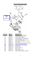
1
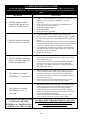
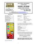
TICKET DISPENSER
KIOSK
OPERATIONS MANUAL
MODEL AC110
American Changer Corp.
1400 NW 65th Place
Ft. Lauderdale, FL 33309
Parts & Service:(888)741-9840
Sales:(800)741-9840
Fax:(954)917-5204
Internet Address: www.americanchanger.com
Service Questions?: E-mail: [email protected]
Rev. UNTK-2A-B05 12.21.06
1
Table of Contents
SECTION 1: SET-UP & INSTALLATION
4
1.1 Uncrating & Setup
4-5
1.2 Ticket Loading
5
1.3 Operating Instructions
6
1.4 Equipment Indicator Lights
6
1.5 Mounting Instructions
7-8
AC110 Program Flow Chart
1.6 AC110 Programming Guide
9-10
9
1.6.1 Standby Operation
9
1.6.2 Accessing Program Menus
9
1.6.3 Setting Bill Acceptance
9-10
1.6.4 Setting Ticket Payouts
10
1.6.5 Hardware Settings
10
1.6.6 Anti-Stringing Protection
1.7 Hopper Information
11
11
1.7.1 Using the Dump Feature
11
1.7.2 Coin/Token Sizes
11
1.8 Fuse
1.9 Out-of-Service Conditions
11-12
11
1.9.1 Blown Fuse
12
1.9.2 Validator Faults
12
1.9.3 Hopper Faults
12
1.9.4 Spiral Board Fault
12
1.9.5 Ticket Dispenser Faults
13
1.10 Board Connector Pin Definitions
13
1.11 Board Descriptions
SECTION 2: BILL VALIDATOR
15
2.1 Removing the Bill Box
15
2.2 Removing a Bill Jam
16-17
2.3 Setting the Bill Types Accepted
2.4 Cleaning the Validator
17-18
18
2.4.1 Cleaning the Sensors
18
2.4.2 Cleaning a Salted Unit
19
2.5 Replacing the Belts
20
2.6 Troubleshooting & Error Codes
SECTION 3: COIN HOPPER
22-23
3.1 Coin Box Removal & Assembly
23
3.2 Exit Window Replacement
24
3.3 Logic Board Replacement
24
3.4 End Plate Removal
3.5 Track Plate Removal
24-26
25
3.5.1 Track Plate Assembly
26
3.5.2 Track Plate Replacement
26
3.5.3 Final Drive Gear Replacement
27
3.6 Gearbox Assembly
27
3.7 Motor Replacement
SECTION 4: COIN ACCEPTOR
29
4.1 Condor Plus Parts & Connectors
29
4.2 Coin Dimensions
29
4.3 Cleaning the Coin Acceptor
4.4 Programming the Coin Acceptor
30-33
4.4.1 Programming Coins/Tokens for
32
Acceptance
4.4.2 Enabling & Disabling
32-33
Coins/Tokens
33
4.4.3 Erasing All Programmed Coins
SECTION 5: TICKET DISPENSER
5.1 Ticket Dispenser Diagram
5.2 Ticket Dispenser Feature Descriptions
5.3 Dispenser Specifications
SECTION 6: TROUBLESHOOTING
6.1 Troubleshooting Guide
SECTION 7: PARTS LISTS
7.1 AC111/115/125 Cabinet Parts
7.2 DL-1275 Ticket Dispenser Parts
7.3 Coinco Validator Parts
35
36
36
37-38
39
40
41-44
Coinco Authorized Service Centers are listed
at the end of this manual (pg. 45)
Specifications
Operating voltage
Power consumption
120 Volts AC; 50-60 Hz.
Controller: 10W, Hopper: 17W max.,
Validator: 60W max.
Interface to Ticket Disp. 12 Vdc; 0.4A avg., 1.7A Max.
Interface to Validator
24 Vdc, MDB Protocol
Interface to Coin Mech. 24 Vdc, Pulse Protocol
Interface to Hopper
24 Vdc, ccTalk Serial Protocol
Operating temperature
32 - 130 degrees Fahrenheit
Warranty
The CoinCo MAG52SA Validator is under warranty for
two years from date of purchase.
The Deltronic Labs DL-1275 Ticket Dispenser, the Money
Controls Universal Hopper, and the AC110’s Main Logic
Board, are under warranty for one year from date of purchase.
COVERED
¥ Defects in workmanship or materials
NOT COVERED
¥ Damage caused by physical abuse
¥ Misapplication
¥ Vandalism
¥ End user’s attempt to repair item on his own
¥ Cleaning & Maintenance
It is the End User’s responsibility to follow proper cleaning &
maintenance procedures. Any unit coming in for repair
requiring only a cleaning will be charged a flat rate of $65.00
plus shipping and handling.
NOTE:
A Return Material Authorization number (RMA#) must be
obtained before returning a unit for repair. A copy of
invoices must accompany any and all warranty work.
2
Attention Please:
To ensure the most trouble-free machine operation, we recommend plugging all our machines into a
DEDICATED AC outlet. (This means there are no other machines on location plugged into the same
AC line.) A simple way to check if this is true is to turn off the breaker at the fuse box associated
with our machine. No other machines on location should lose power or turn off.
If this is a concern for your area of business, we recommend purchasing a surge protector locally
NOTE: A POWER STRIP IS NOT A SURGE PROTECTOR.
AC __________ S/N# _________________________
Tested By ___________________________
Date __________________
Thank You,
American Changer Corp.
3
1.1 UNCRATING AND SET-UP
1.2 TICKET LOADING
Remove your AC110 Series ticket dispenser from the
shipping box. To open the door, take the Hex handle out of
the envelope that this manual came in. The locks are the
screw-in type, so insert the handle into the hole, and turn it
counter-clockwise at least 10 times until the door opens.
Inspect for any connectors or components that may have been
dislodged during shipping.
It is not necessary to detach the main body of the
Ticket Dispenser from the door in order to load tickets.
1.
To re-close the door, hold it closed and insert the Hex handle
into the hole, turning it clockwise until tight. The lock and
keys for your dispenser will be inside the manila envelope
also. To install the lock, insert the cylinder into the round
hole so its notch lines up with one of the grooves, and push it
all the way back until it stops. Turn the key exactly ¼-turn
counter-clockwise, and remove the key.
2.
3.
NOTE: The only way to get a duplicate
set of keys made is to save the silver
tag that comes between the keys.
Write your ID# here:
.
4.
TEST:
Before permanently installing the dispenser, do a functional
test to verify that there is no shipping damage to your new
dispenser.
1.
2.
3.
4.
5.
6.
7.
8.
Install the Coin Bin on the right sidewall of the inside of
the unit. Slide the studs through the ‘keyholes’ on the
side of the bin, and push down to lock the bin in place.
The chute should be facing forward, toward the door.
Install the Ticket Bin on the inside of the door,
underneath the dispenser. Slide the studs through the
‘keyholes’ on either side of the bin, and push down to
lock it in place.
Install the Coin Hopper on the Hopper Plate located on
the left side of the cabinet interior. Hold the Coin
Hopper so its green connector is pointed toward the rear
of the cabinet, line up the grooves on the underside of
the Hopper with the Hopper Plate, and slide the Hopper
all the way back until it stops.
Plug the power cord into a grounded 120VAC outlet.
The Main Logic Board programming is preset for the
default payout that was specified at the time of purchase,
and the Bill Validator is configured to accept all of the
required bills. No programming is required.
Fill the Ticket Bin with tickets, and load the dispenser
by following the Ticket Loading instructions on pgs. 4-5.
If you are going to use the Coin Hopper, fill it with the
coins or tokens you would like to dispense. The Hopper
must be filled with at least enough coins to cover the
two gold-colored metal plates at its bottom!
Test the operation of the machine by following the
Operating Instructions on page 5.
If there are tickets remaining in the dispenser, remove
them before proceeding, and empty the ticket bin.
Loosen the grip of the Validation/Embossing rollers by
pressing the metal plate and metal spacer toward each
other using your thumb and forefinger (apply pressure at
the points indicated by the two white arrows in Fig. 1).
While applying pressure with one hand, use your other
hand to pull the tickets back out of the mechanism.
Refill the ticket bin with a fresh box/pack of accordionstyle folded tickets. Use 1-5/32” width tickets ONLY!
Pull the top row of tickets up, and feed them face-up into
the entrance of the ticket dispenser mechanism, between
the top and bottom metal ticket guides. If necessary,
reverse the Ticket Bin so the tickets can be directed into
the dispenser face-up. Gently push the Locating Spring
to the right, out of the ticket path, with one hand while
feeding the tickets with the other (refer to Fig. 2).
IMPORTANT! When inserting the tickets, make sure that
they pass through the slot in the Optical Sensor.
Continue to push them in until the front ticket presses
against the back of the Validation/Embossing rollers
(refer to Figs. 1 & 2).
Locating
Spring
(push right)
Optical
Sensor
Ticket
Guides
Figure 1: DL-1275 Ticket Dispenser
4
5.
Locate the DOWN (▼) button on the Main Logic Board
(see Fig. 4). Press and hold the DOWN button to
initiate the Ticket Auto-Feed feature of the AC110. After
one second, the display will prompt: ‘Feed Tickets?’ to
alert the user that the Ticket Auto-Feed feature has been
activated. Continue holding the DOWN button for three
more seconds (total = 4 seconds), until the dispenser
motor begins to run, and then release the button. AutoFeed can be cancelled at any time before the dispenser
motor turns ON simply by releasing the DOWN button.
1.3 OPERATING INSTRUCTIONS
This section describes the standard operation and features of
the AC110 Ticket Dispenser Kiosk.
1.
During the Auto-Feed procedure, the tickets are pulled
through the dispenser’s ticket path, and automatically
fed to the proper “standby” position, which is flush with
the front of the machine. If the motor starts running but
the tickets are not being pulled in, gently apply forward
pressure to the ticket string until the rollers grip the
tickets, and they are drawn in.
2.
3.
4.
Note: One or more tickets may be fed out through the
slot during the Auto-Feed operation; these may be torn
off and discarded.
5.
Validation/
Embossing
Rollers
6.
7.
Figure 2: Ticket Loading
5
Locate the power switch on the bottom right side of the
Power Supply Board, and turn it ON (refer to Fig. 4 on
pg. 13) The rocker switch has an “I” and an “O”
printed on it. When the “I” is pressed down the power is
ON. Wait at least 30 seconds after powering ON the unit
before inserting any bills to allow it to finish its start-up
procedure.
Close and lock the door of the unit.
Insert a bill into the Bill Validator, or a coin into the
Coin Acceptor. NOTE: By default, the Coinco Validator
will only accept bills face-up, in either direction, but the
MEI (Mars) Validator will accept bills in all four
directions. Refer to your Validator‘s Section in this
manual to change this.
Continue adding bills or coins into the machine, and the
amount of money entered will accrue. When the money
total reaches the set price of the least expensive button,
that button will begin blinking. As more money is added
and the total continues rising, each of the other buttons
will begin blinking as their set prices are reached. The
blinking indicates that the button has become active, and
will trigger the machine to pay out when pressed.
When a selection is made, by the pressing of a single
button, the set number of tickets will be dispensed
through the ticket slot in the front door. Only tickets will
be dispensed if the amount of money accrued by the
machine was exactly equal to the button price. If more
money was entered into the machine than the price of the
button pressed, the hopper will automatically dispense
the amount of change owed.
Once the ticket dispensing and change payout, if
necessary, is complete, the machine is ready to begin
accepting money for another transaction.
If, at any time, the red “Out-of-Service” light on the
front door turns ON solid, the Bill Validator and the
Coin Acceptor will be disabled, and the machine will
cease operation. This can happen for a number of
reasons, including running low on coins, running out of
tickets, or an error such as a bill jam in the validator.
When the “Out-of-Service” light is lit, please do the
following:
A. Unlock and open the front door, so the LCD screen
on the Main Logic Board can be seen.
B. Read the Error Message that is being displayed on
the screen, and take the appropriate action(s) to
correct the problem (refer to the Troubleshooting
section of this manual for details).
C. Turn OFF the power to the Main Logic Board, wait
at least 10 seconds, and then turn the power back
ON, to clear the Error Message.
4.
1.4 EQUIPMENT INDICATOR LIGHTS
Main Logic Board:
1. Red LED
A. Heartbeat – 24, 5, and 3.3Vdc present; the Main
Logic Board is operating normally.
2. LCD Display Backlight
A. ON Steady – Normal operation; this applies to both
Standby and Programming modes.
B. Blinking – Error condition present; the backlight
blinks synchronously with the Red LED (see pages
11-12 for error message descriptions).
5.
6.
7.
Power Supply Board:
Green LED
A. ON: AC power applied to the board, and 24 VDC
present on secondary side. Main fuse is good.
B. OFF: No power. Make sure the ON/OFF switch is
in the “I” position; check the AC power cord
connection; check the main fuse; check for shorts of
the validator, hopper, ticket dispenser, or main
transformer.
1.
8.
9.
Validator logic board:
1. Red LED
A. ON Steady - Standby mode; waiting for bill to be
inserted.
B. Flashing - Error mode; see page 20 for error code
descriptions.
C. OFF - The “Out-of-Service” LED is lit and the
Main Logic Board has shut down the validator, or
the unit is not receiving power.
10.
11.
Spiral Board:
1. Red LED
A. Heartbeat – 24, 5, and 3.3Vdc present; the Spiral
Board is operating normally.
2. Green LED
A. ON – 24Vdc present from Main Logic Board.
B. OFF – The unit is not receiving power. Make sure
the Main Logic Board is switched ON; check the
Spiral Board Harness connection.
12.
13.
14.
1.5 MOUNTING THE AC110
15.
IF YOU ARE UNSURE IN ANY WAY IN PROCEEDING
WITH THE FOLLOWING STEPS, PLEASE HIRE A
LOCAL PROFESSIONAL ELECTRICIAN TO MOUNT
YOUR CHANGER FOR YOU!
1.
2.
3.
Disconnect any and all AC power going to the AC110
kiosk (unplug the AC Line cord from the wall).
Remove the Hopper, the Ticket Bin, and the Coin Bin
from the cabinet.
Note: You will need to verify with the building code if
it is allowable to plug the changer into a 3-prong
grounded outlet. If it is not, there must be 120VAC run
through conduit, or other means that meet local codes, to
the changer. If conduit is not required, proceed to step
#6.
6
Let the electrician run the conduit, install the new
breaker, wire, and help decide how the wiring will enter
the changer (from the back or the left side).
After the conduit has been installed, proceed with the
mounting.
Find an appropriate space on the floor to bolt the ticket
kiosk into. Depending on what the floor is made of, the
appropriate bolt anchors should be used. Consult a
professional with any questions you may have.
NOTE: MOUNTING THE KIOSK WITH LESS
THAN THE FOUR HOLES PROVIDED MAY BE
DANGEROUS. EACH HOLE NEEDS AT LEAST A
¼” BOLT THROUGH IT, TIGHTENED SECURELY
TO THE FLOOR. MOUNTING THE UNIT IN ANY
OTHER WAY MAY RESULT IN THE KIOSK BEING
TORN OUT OF THE FLOOR OR TIPPING OVER,
RESULTING IN PERSONAL OR CUSTOMER
INJURY ALONG WITH ELECTRICAL SHOCK.
Slide the AC110 into the desired final mounting
location. CAUTION: THE CHANGER WEIGHS 120
POUNDS; DO NOT EXERT YOURSELF SO THAT
YOU MAY CAUSE AN INJURY.
Locate the four mounting holes at the base of the
cabinet, and mark their locations with a permanent
marker or other legible marking device.
Move the AC110 out of the way, drill the holes, and
insert the appropriate anchors, if necessary.
BEFORE DRILLING THE MARKED HOLES,
ENSURE THAT THERE ARE NO ELECTRICAL
WIRES, TELEPHONE LINES, GAS OR WATER
LINES UNDER THE FLOOR, WHICH DISRUPTING
MAY CAUSE A LOSS OF LIFE OR PERSONAL
INJURY!
Slide the kiosk back into position, lining up the holes in
the cabinet with the holes just drilled in the floor. Thread
and tighten all four bolts.
Verify that the machine is securely mounted.
If the changer is to be permanently connected through a
conduit, proceed to step #15.
Feed the AC line cord out through the back or the left
side of the changer by swapping the two brackets, if
necessary, and then perform the following:
A. Plug the male end into the AC wall outlet. Do not
use an extension cord unless allowed by the
building electrical code.
B. Installation is finished.
In order to continue you will need to purchase numerous
electrical components. We highly recommend HIRING
a qualified electrician to perform the following!
A. Install the conduit box on the conduit entering the
cabinet through the back or left side of the cabinet.
B. Secure the 3 wires (hot, neutral, and ground) to the
AC wall outlet. The ground wire should also be
directly attached to the cabinet ground terminal.
C. Plug the male end into the AC outlet just installed.
D. Properly fold the line cord to avoid sharp corners
and any other damage.
E. Installation is finished.
AC110 TICKET DISPENSER PROGRAM FLOW CHART
MAIN
$000000
00¢
PAYOUT
BILLS
VALUE #1
EXIT
HARDWARE
(Hardwr)
EXIT
* PAGE 8 *
Set Button #1 Value:
$0.25 - $99.00
ACCEPT
SECURITY
(Sec.)
BILL #1
SECURIT
VALUE #2
Choose Enable,
Disable, or Exit
Choose
High, Low,
or Exit
Set Button #2 Value:
$0.25 - $99.00
BILL #2
VALUE #3
TICKETS2
Choose Enable,
Disable, or Exit
Set Button #3 Value:
$0.25 - $99.00
Set Button #2 Tickets:
000 - 999
BILL #3
VALUE #4
TICKETS3
Choose Enable,
Disable, or Exit
Set Button #4 Value:
$0.25 - $99.00
Set Button #3 Tickets:
000 - 999
BILL #4
TICKETS1
TICKETS4
Choose Enable,
Disable, or Exit
Set Button #1 Tickets:
000 - 999
Set Button #4 Tickets:
000 - 999
BILL #5
HOPPER
Choose Enable,
Disable, or Exit
Set Coin/Token Value:
$0.25 - $99.00
7
SW Version UNTK-2A-B05
AC110 TICKET DISPENSER PROGRAM FLOW CHART
HARDWARE
(Hardwr)
COIN
ACCEPTOR
(CoinAcc)
HOPPER
STRING
DUMP
HOPPER
Choose Enable,
Disable, or Exit
EXIT
DUMP
PULSE
NONE!
Choose Enable,
Disable, or Exit
EXIT
ENABLE
Choose
High, Low,
or Exit
ENABLE
DISABLE
EXIT
MAX $
Set value
$020 - $200
MAX TIME
Set minutes
005 – 120
SHUT OFF
Set 15, 30, 45, 60
min., or Reset
8
SW Version UNTK-2A-B05
of a series will return the program to Standby mode
WITHOUT saving any changes.
1.6 GUIDE TO PROGRAMMING THE
AC110 TICKET DISPENSER KIOSK
CAUTION: The software settings on the Main Logic Board are
programmed at the factory, and do not need to be altered under
normal circumstances. Only if you wish to change the operation
of your ticket dispenser should you enter the Program Mode to
make changes.
1.6.3 SETTING BILL ACCEPTANCE
BILLS:
The first menu item contains settings that affect the Bill
Validator.
The following is a description of the various menu options that
are available in the Ticket Dispenser software. Read the
following for a detailed explanation of the menus that are used,
as well as instructions on how to access the Program Mode and
how to make and save your desired changes. It may be helpful to
follow along in the Program Flow Chart on pages 7-8 while you
read through the menu descriptions.
Accept: This submenu is used to specify which bill
denominations will be accepted by the validator. Choose
whether to accept (Enable) or reject (Disable) each bill
denomination in sequence. Note: The validator also has DIP
switch settings for individual denomination acceptance. Both
the validator and the Logic Board must be set to ‘Accept’ or
‘Enable’ for a bill to be accepted. Refer to the validator
section of this manual for information on the validator’s DIP
Switch settings (Factory default settings from American
Changer enable all bills on the validator’s DIP switches, so
they do not need to be changed; all settings can be made with
the Main Logic Board).
1.6.1 STANDBY OPERATION
When the AC110’s Main Logic Board is powered-ON, the unit
will begin to run through a start-up procedure, which may take
up to thirty seconds or more. During this time, the Bill Validator
is being initialized, so its motors may be heard cycling as the
Main Logic Board (MLB) checks them; this is normal. Do not
attempt to insert a bill into the validator while it is being
initialized, as it will only be rejected. The Ticket Dispenser will
be in the Standby state, ready to accept bills, once all motion has
ceased, and all indicator lights are showing a “Ready” condition.
In this state, the MLB’s LCD display will be illuminated by its
backlight continuously, and the screen will show the current,
non-resettable total of money that has been accepted by the
machine ($000000, 00¢). Additionally, the red LED, located
above the LCD display on the Main Logic Board, will blink a
“heartbeat” every second to indicate that the unit is getting power
and functioning normally.
Security: This setting applies to ALL bills. Set whether to
use High or Low security scanning of bills by the validator.
High security scanning limits bill acceptance parameters and
makes it more difficult to pass a counterfeit bill. For this
reason, though, high security may require a “crisper” or
newer bill for acceptance, and may not accept an older
“tissue-paper”, yet legitimate, bill that low security might.
Choose High for better security, or Low for a better
acceptance rate.
1.6.4 SETTING TICKET PAYOUTS
PAYOUT:
Enter this menu to set the purchase price and ticket quantity
for each of the AC110’s four selection buttons. The first four
settings in this menu are called “Value” settings, and are the
purchase prices for the four different ticket packages
available with buttons 1-4. Use the UP and DOWN buttons to
modify the current selection button price to between $0.25
and $99.00 in $0.25 increments, and then press the SELECT
button to save it and move to the next setting.
1.6.2 ACCESSING THE PROGRAM MENUS
The AC110 Ticket Dispenser’s default operational settings are
easily reprogrammed to meet your requirements. Programming is
done using the three buttons and the LCD display, located on the
Main Logic Board, as an interface (see Figure 3).
When the unit is in the Standby mode, pressing the SELECT
(SEL) button once enters the Program mode. The Program mode
contains menus, many of which contain submenus, where the
board’s operational settings can be viewed, altered, and saved.
Inside the Program mode, the SELECT button is used to both
access menus and their submenus, and then save any changes
when made. The other two buttons, UP (▲) and DOWN (▼), are
used to move the cursor and to increase or decrease user-set
values. In simple terms, enter the Program mode by pressing the
SELECT button, navigate through the menus using the UP,
DOWN, and SELECT buttons, modify the settings with the UP
and DOWN buttons, and then save the settings with the SELECT
button. Choosing ‘Exit’ in any menu will take the program out of
Program mode, and back to Standby mode.
After the last “Value” setting, for button #4, the next four
settings are the ticket quantities for buttons 1-4, in order. The
“Tickets” quantities are the number of tickets that will be
dispensed when a particular selection button is pressed, and
can be set to any number between 0 and 999. NOTE: Setting
the ticket quantity for any selection button to zero (000) will
DISABLE that button, meaning its “Value” will be ignored,
and it will never become active or blink.
After the last ticket quantity setting, for button #4, the final
setting is the value of the coins or tokens to be dispensed by
the hopper. This value can be set to any amount between
$0.25 and $99.00 in $0.25 increments, and is the number
used by the Main Logic Board to calculate the quantity of
coins or tokens that will constitute any change that may be
necessary.
Note: Some of the menu items contain a series of settings. For
example, the ‘Accept’ submenu under ‘Bills’ contains up to five
bill denominations to choose whether to accept or reject. These
settings must be done in sequence, all the way through, for any
changes to be saved. Choosing ‘Exit’ at any point in the middle
9
EXAMPLE #1: With the Payout settings as follows:
Button #1 = $1.00, 1 ticket
Button #2 = $5.00, 5 tickets
Button #3 = $10.00, 12 tickets
Button #4 = $20.00, 25 tickets
Hopper = $0.25 (Quarters)
A customer who does not have a $20 bill, but has one $10 bill
and two $5 bills can still buy the $20.00 package and get the 5
bonus tickets by inserting all three bills and pressing button #4.
enable line is a way for the Main Logic Board to disable the
functioning of the Coin Acceptor when there is an error
condition.
Dump: The coin “Dump” feature is a way to empty the
hopper, and count the coins at the same time, without having
to take it out of the cabinet (refer to the Hopper Information
section on page 11). Choose whether to Enable or Disable the
Dump feature inside this submenu.
EXAMPLE #2: With the Payout settings as follows:
Button #1 = $1.00, 4 tickets
Button #2 = $5.00, 20 tickets
Button #3 = $10.00, 40 tickets
Button #4 = $20.00, 80 tickets
Hopper = $1.00 (Dollar Coins)
A customer who has a $20.00 bill, but who wants to purchase
only $5.00 worth of tickets can insert the $20.00 and press button
#2. 20 tickets will be dispensed, along with 15 $1 coins for
change.
1.6.6 ANTI-STRINGING PROTECTION
HARDWARE: STRING:
The third submenu inside the Hardware menu is used for
Enabling or Disabling the Ticket Dispenser’s Anti-Stringing
Protection feature. “Stringing” refers to a method of
defrauding any machine that uses a Bill Validator using
string or tape attached to the end of a bill. The bill is inserted
into the machine, and is yanked back out using the string or
tape attachment after the Validator has credited the money.
This results in the thief getting his bill back, in addition to the
change or other item(s) dispensed by the machine. The
AC110’s Anti-Stringing Protection feature will not totally
prevent the machine from getting “strung”, rather it is a
method of limiting the amount of tickets and/or money the
thief is able to steal from the machine.
NOTE: Always run tests once the values and ticket quantities for
the four selection buttons have been set, to be sure they are
correct and how you want them before final installation of the
kiosk. The payouts can be set and reset as often as needed, and
can be changed at any time to meet your requirements.
Choose Enable to Disable after entering the “String”
submenu. If Enable is chosen, the display will then prompt
you to make a series of three settings that control the
behavior of the machine with regard to stringing. These are
each explained in detail in the following paragraphs.
1.6.5 HARDWARE SETTINGS
HARDWARE:
The ticket dispenser’s Hardware settings menu contains, as one
may expect, settings that control the function of the unit’s
different hardware devices. It includes submenus for the Coin
Hopper and the Coin Acceptor, and also submenus for
controlling the Coin “Dump” and Anti-Stringing Protection
features. Hardware settings for the machine are made at the
factory when ordered, so they should not need to be accessed,
unless the operation of the ticket dispenser is to be modified,
with the exception of Anti-Stringing Protection. It is at the
owner’s discretion whether or not to implement the AntiStringing Protection feature, so, if enabled, there are some
settings that are required.
Max $: This setting is the maximum dollar amount that can
be accepted by the machine within the user-set time limit
(next setting) before triggering the Anti-Stringing Protection.
The dollar amount can be set anywhere between $20 and
$200 in $5 increments.
Max Time: The time entered here is the time limit for the
changer accepting the user-set maximum dollar amount
(previous setting). If the changer accepts the maximum dollar
amount within the amount of time set here, the AntiStringing Protection feature will be triggered. The length of
time can be set to anywhere between 5 and 120 minutes in 5
minute increments.
Hopper: In this submenu, choose whether to Enable or Disable
the use of the Coin Hopper. The Ticket Kiosk is designed for use
with a hopper, but in the event that the hopper is not working,
this setting allows the machine to continue dispensing only
tickets by suppressing the hopper errors. NOTE: When
disabling the hopper, it must be disconnected from the system.
Either remove the hopper from the cabinet completely, or unplug
the hopper harness from the Main Logic Board’s hopper
connector (refer to Figure 4).
Shut Off: This setting controls the length of time that the
Anti-Stringing Protection, which is the shutting down of the
changer, remains active for. The changer can be set to shut
down, or go “Out-of-Service”, for 15, 30, 45, or 60 minutes,
or until the Logic Board is reset by turning the power off
then back on (‘Reset’). When the “Shut Off” time has
elapsed, or the Logic Board is reset, the machine will begin
to operate normally again.
Coin Acceptor: There are three initial menu choices in the Coin
Acceptor submenu. These are Pulse, None!, and Exit. Press
SELECT to choose Pulse if a Coin Acceptor that uses pulse
communication is connected; this is the only type currently
available for use in the AC110. The included Condor Plus Coin
Acceptor is a Pulse Coin Acceptor, so choose Pulse if it is to be
used. Choose None! if there is no Coin Acceptor connected, or
Exit to go back to Standby mode without saving any changes.
---[END PROGRAMMING SECTION]---
If Pulse is chosen, the display will prompt you to choose the
logic level that will “Enable” the connected Coin Acceptor, High
or Low. Choose “High” if using the standard Condor Plus. The
10
1.7 HOPPER INFORMATION
1.7.2 HOPPER COIN/TOKEN SIZES
1.7.1 USING THE HOPPER DUMP FEATURE
The standard hopper will automatically dispense coins/tokens
that are between 21 - 30 mm in diameter and 1.25 - 3.5 mm
in thickness. There are options available for this hopper to
dispense either smaller or larger coins, with the overall range
being 16 – 31 mm in diameter. If you would like to dispense
coins that are outside of the standard hopper’s size range,
please contact American Changer.
A nickel is approximately 21.2 mm, a quarter is
approximately 24.3 mm, and both Susan B. Anthony and
Sacagawea “Golden” dollar coins are approximately 26.5
mm in diameter.
NOTE:
The Dump feature must be ENABLED in the
‘Hardware’: ‘Dump’ menu in order for the following to work
(refer to page 10).
1.
2.
3.
4.
5.
Open the Ticket Dispenser door to gain access to the MLB
and the hopper.
Place a suitable container, or bag, in front of the hopper’s
Coin Exit to catch the dispensed coins/tokens.
Locate the UP (▲) button on the Main Logic Board (see
Fig. 4). Press and hold the UP button to initiate the Hopper
Dump feature of the AC110. After one second, the display
will prompt: ‘Dump Hopper?’ to alert the user that the
Hopper Dump feature has been activated. Continue holding
the UP button for three more seconds (total = 4 seconds),
until the Coin Hopper motor begins to run, and then release
the button. The coin “Dump” can be cancelled at any time
before the hopper motor turns ON simply by releasing the
UP button.
After the hopper begins emptying, it will continue to run
until manually stopped by pressing the SELECT (SEL)
button on the Main Logic Board. It may be stopped at any
time, or allowed to run until empty.
Note the LCD Display while the Hopper is running. A count
of the number of coins being dispensed is displayed, and is
continually updated during the “Dump”. If allowed to
continue until the Hopper is completely empty, this count
will show the quantity of coins/tokens that were in the
Hopper before dumping commenced.
1.8 FUSE
High voltage fuse: This is the primary transformer AC fuse
for the Main Logic Board, from which the Validator and
Hopper, if installed, draw their power (refer to Figure 4 for
location). Any direct short of the Transformer, Validator, or
Hopper will cause this fuse to blow. Replace this fuse with a
2-½ Amp, 250 Volt, size: 5mm x 20mm, fast-acting fuse
only. REPLACING THIS FUSE WITH ANYTHING
OTHER THAN A 2-½ AMP FAST-ACTING FUSE MAY
RESULT IN A FIRE OR AN UNSAFE WORKING
CONDITION!
1.9 OUT-OF-SERVICE CONDITIONS
Out-of-Service conditions occur in the AC110 Ticket
Dispenser Kiosk for the following reasons: blown fuse,
validator, hopper, or spiral board fault, or out of tickets.
Hopper Coin Bin
(Load the coins
into this hole;
1600 quarters
max.)
1.9.1 Blown Fuse: A spike in the AC line voltage or a bad
transformer on the Power Supply board can cause a blown
fuse. If the primary fuse blows, the indication is that the
green LED on the Power Supply will not light.
1. Replace the fuse. If the green LED now lights then there
was a spike.
2. If it does not light and the fuse blows again, disconnect
the hopper and validator connectors and try again. If the
green LED stays lit, reconnect each component one at a
time until you find the one blowing the fuse.
3. If the fuse still blows with all components removed from
the MLB, the power transformer is shorted. To test the
transformer, use a multimeter set for ohms and measure
across the primary (~40ohms) and the secondary
(~1.5ohms).
Coin Exit Window
(Coin Counting &
Security Optical Sensors)
12-pin Female
Connector
(on opposite side)
Motor
Figure 3: Coin Hopper
11
7.
1.9.2 Validator Faults: When a validator fault occurs, the
validator’s EEPROM shuts down the validator and sends an error
code to the Logic Board’s LCD display. The Out-of-Service light
on the front of the machine will illuminate for a validator fault.
1. Validat. Full – The Bill Stacker is full of bills and should
be emptied.
2. Validat. Motor – Motor failure. Either the Stacker or
Transport motor has a failure; repair or replace the unit.
3. Validat. Sensor – One of the sensors inside the validator is
not operating properly. Check for a jammed bill; if that is
not the cause, repair or replace the validator.
4. Validat. Checksum – Checksum failure. The validator’s
Logic Board programming has been corrupted; repair or
replace the validator.
5. Validat. CashBox – The Bill Stacker has been removed
from the validator and should be replaced.
6. Validat. NoComm – There is a communication failure
between the changer’s Main Logic Board (MLB) and the
validator. This may be a temporary condition while one of
them is completing some task, the wiring harness may be
loose or unplugged, or the validator may need to be repaired
or replaced.
7. Validat. Disabled – The MLB cannot enable the validator,
due to an internal error inside of the validator. This may be
a communication issue, and may be temporary.
8. Validat. String – The changer’s Anti-Stringing protection
has shut down the machine’s operation. Basically, more
money has been paid out in less time than allowed by the
system’s settings (see pg. 10 for Anti-Stringing protection
setup). Wait the allotted time, or cycle power to the MLB to
resume operation.
9. Validat. Pulse – The pulse validator being used has been
disabled. Check the unit and repair or replace as necessary.
10. Busy – This message is displayed whenever the validator is
in the process of validating (accepting) or stacking a bill.
Hopper Low – This is the most common error; it
signals Low Coins in the hopper. Refill the hopper with
coins or tokens. If you have enough coins in the hopper
to cover the gold-colored plates at the bottom of the coin
bin, but you are still getting this message, try the
following:
A. Ensure the coins have not bridged inside the
hopper coin bin, preventing them from reaching
the bottom, where the Elevator Track picks them
up.
B. Clean the gold-colored plates at the bottom of the
coin bin with EMERY cloth or fine sandpaper, so
they are shiny. Refill the hopper and try again.
C. Using an ohmmeter, check the continuity of the
hopper harness from the 12-pin connector back to
the logic board. You should get ~0 ohms for each
line.
If none of this works, the unit may need repair or
replacement.
1.9.4 Spiral Board Fault: The Spiral Board directly
interfaces with the four ticket selection buttons, and
communicates with the Main Logic Board using ccTalk
communication protocol.
1. TicketNoComm – This is the only Spiral Board error
message, and it signals a loss of communication
between the Spiral Board and the Main Logic Board.
Make sure the wiring harness between the two is
connected properly (see Figures 4 & 5), and, if it is,
check it for continuity.
1.9.5 Ticket Dispenser Faults: The Deltronic Labs DL1275 is a passive device, in the sense that it is merely turned
ON to dispense tickets, and OFF to stop dispensing them by
the Main Logic Board. As such, it is limited to out-of-service
conditions that involve only Low Tickets.
1. Tickets 0000 – This error code is displayed when the
machine runs out of tickets in the middle of a payout
operation. The “0000” will be a 4-digit number
indicating the amount of tickets that could not be
dispensed, and are owed to the previous customer in
order to complete the transaction. NOTE: Actually,
there will be 2 tickets remaining inside the dispenser.
This is a necessary remainder, because of the
dispenser’s sensor location, to prevent any extra, unpaid-for, tickets from being dispensed. Refill the Ticket
Bin with tickets, and load the dispenser by following the
Ticket Loading instructions on pages 4-5.
2. Ticket TimeOut – This is a special case of the “Tickets
0000” error message that will be displayed only when
the machine runs out of tickets, but none are owed to the
previous customer. The last payout was completed, but
the dispenser’s sensor recognized the end of the ticket
string, so no further ticket payouts are possible. NOTE:
2 tickets will remain inside the dispenser. Refill the
Ticket Bin with tickets, and load the dispenser by
following the Ticket Loading instructions on pages 4-5.
1.9.3 Hopper Faults: Hopper faults occur for a variety of
reasons, but the most common in any coin machine is always low
coins. Any of the hopper faults will cause the Out-of Service
light on the front of the machine to illuminate.
1. Hopper NoComm – The changer’s Main Logic Board is
unable to communicate with the hopper. This may be a
temporary condition, or the wiring harness may be loose or
unplugged, or the hopper may need to be repaired or
replaced. Note: The hopper must be plugged into the proper
connector (see Fig. 4).
2. Hopper NoPay – This code signifies that a payout signal
was sent to the hopper, but the hopper did not dispense any
coins/tokens. Check the hopper for a possible coin jam, exit
blockage, or other mechanical fault. If nothing can be found,
have the unit repaired or replaced.
3. Hopper OptoBlkd – An optical sensor near the exit
window is being blocked. The exit path may be obstructed,
or the Optic Board may be bad. Repair or replace.
4. Hopper Current – The maximum current level for the
hopper is being exceeded. Inspect for a jammed coin
preventing the coin Elevator Track from moving, or a
stalled or shorted motor. Repair or replace the hopper.
5. Hopper Fraud – Something blocked the Hopper’s security
sensor. Inspect for a jammed coin or other obstruction near
the coin exit window; repair or replace the hopper.
6. Hopper TimeOut – The coins/tokens were not dispensed
from the hopper within a specific time. Check the hopper for
any coin jams or mechanical obstructions preventing coins
from exiting. Have the unit repaired or replaced.
12
1.11 BOARD DESCRIPTIONS
1.10 BOARD CONNECTOR PIN DEFINITIONS
“Out-of-Service” LED Connector:
Pin 1 - +24Vdc
Pin 2 - Switched Ground
5
6
4
Spiral Board Connector:
Pin 1 - Ground
Pin 2 - +24Vdc Power
Pin 3 - +5Vdc
Pin 4 - N/C
Pin 5 - ccTalk Data
Pin 6 - N/C
Pin 7 - Ground
7
8
9
1
2
3
14
Hopper Connector:
Pin 1 - Ground
Pin 2 - +24Vdc Power
Pin 3 - +5Vdc
Pin 4 - N/C
Pin 5 - ccTalk Data
Pin 6 - Address Select
Pin 7 - Ground
10
12
Coin Acceptor Connector:
Pin 1 - +24Vdc Power
Pin 2 - Coin Pulse
Pin 3 - Pull-up
Pin 4 - Enable
Pin 5 - Ground
Pin 6 - Ground
13
11
Figure 4: Main Logic & Power Supply Boards
15
16
MDB Bill Validator Connector:
Pin 1 - +24Vdc Power
Pin 2 - Ground
Pin 3 - Master Transmit
Pin 4 - Master Receive
19
Ticket Dispenser Connector:
Pin 1 - Ground
Pin 2 - Switched +24Vdc Power
Pin 3 - Ground
Pin 4 - Ticket Notch Sensor
Pin 5 - Sensor Input - NOT USED
18
17
Figure 5: Spiral Board
Power Cord Connector:
Pin ‘N’ - AC Power Neutral
Pin ‘E’ - Earth (Cabinet) Ground
Pin ‘L’ - AC Power 120V Line
(1)
(2)
(3)
(4)
(5)
(6)
(7)
(8)
(9)
(10)
(11)
(12)
(13)
(14)
(15)
(16)
(17)
(18)
(19)
Button 1-4 Connectors:
Pin 1 - Lamp (+)
Pin 2 - Lamp (–)
Pin 3 - Ground
Pin 4 - N/O Switch
Pin 5 - LED (+) - NOT USED
Pin 6 - LED (–) - NOT USED
Main Logic Board Connector:
Pin 1 - Ground
Pin 2 - +24Vdc Power
Pin 3 - N/C
Pin 4 - N/C
Pin 5 - ccTalk Data
Pin 6 - Address Select
Pin 7 - Ground
13
UP (▲) Button
DOWN (▼) Button
SELECT (SEL) Button
Out-of-Service LED connector
Spiral Board Connector
Hopper Connector
Coin Acceptor Connector
MDB Bill Validator Connector
Ticket Dispenser Connector
Power Switch (I = ON, O = OFF)
Fuse (See Section 1.8 on page 11)
Power Cord Connector
Power Supply Board
Main Logic Board
Button #1 Connector
Button #2 Connector
Button #3 Connector
Button #4 Connector
Main Logic Board Connector
2. COINCO MAG52SA
VALIDATOR SECTION
PAGE
14
2.1 Removing the Bill Box
15
2.2 Removing a Bill Jam
15
2.3 Setting the Bill Types
Accepted
16-17
2.4 Cleaning the Validator
17-18
2.4.1 Cleaning the Sensors
18
2.4.2 Cleaning a Salted Unit
18
2.5 Replacing the Belts
19
2.6 Troubleshooting & Error
Codes
20
2.1 REMOVING THE BILL BOX
To remove the 500-bill stacker from the CoinCo validator, follow the picture below.
2.2 REMOVING A BILL JAM
From time to time a foreign object or ripped bill will become caught in the validator. Follow the
picture below to remove the item.
15
2.3 SETTING THE BILL ACCEPT DIP SWITCHES
16
(FACTORY DEFAULT
SETTINGS)
2.4 CLEANING THE BILL VALIDATOR
Refer to the pictures below, and the procedure on the next page to clean the bill validator every 46 months.
17
MAG CLEANING: IF ANY OF THESE PROCEDURES ARE PERFORMED TO YOUR VALIDATOR AFTER IT IS RETURNED
UNDER A WARRANTY REPLACEMENT, YOU WILL BE SUBJECTED TO A $65.00 LABOR FEE.
2.4.1 CLEANING THE SENSORS:
Note: Petroleum-based cleaners and Freon-based propellants can damage plastic and some electronic components.
Scouring pads and stiff brushes may harm the protective conformal coating on the circuit boards and can mar the plastic.
These
items
should
never
be
used
when
cleaning
the
MAG
bill
acceptor.
4.
5.
6.
Remove the lower housing.
Remove the bottom cover from the lower housing.
Run hot water (1101/4-1401/4F) over the lower
housing from the top and bottom. Using a soft brush,
gently clean any residual salt. Use a soft absorbent
cloth to clean any residue off the lower housing. If
the transformer gets wet, allow the unit to dry for 24
hours before applying power.
7. Remove the front mask. Using hot water and a soft
brush, clean the front mask, upper sensor board,
main frame anti-pullback levers and position sensor
mount.
Caution: The motors are not protected from water,
therefore the unit must be held in a manner that prevents
water from running over the intermediate frame crossbar.
8. Remove the position sensor cover on the crossbar
and carefully lift the LED from its mount. (Early
models only.)
Caution: Protective coating on the LED leads should not
be damaged. Clean all salt residue from the mount,
sensor hole and detector area. The detector can be seen
through the sensor hole, and is located in the chassis.
Replace the position sensor cover. (Early models only.)
9. Verify that the anti-pullback levers move freely and
that the spring returns them to their open position.
10. Allow the unit to dry thoroughly.
11. Clean the magnetic head using a swab and isopropyl
alcohol.
12. Replace the front mask.
13. Replace the lower housing cover.
14. Replace the lower housing into the main frame.
15. Remount the bill box.
16. Apply power and insert bills to verify that the unit is
functioning properly.
6 OR 7 ERROR CODE FLASHES
The cleaning procedure for this common occurrence is
listed below. Just follow these steps.
1. If this code has occurred on a new machine or one
that the validators DIP switches were just changed,
Ensure that all the white plugs on the side of the
validator board away from the red LED are plugged
in securely.
2. Remove the bill box.
3. Turn the Changer ON then OFF in an attempt to stop
the metal push plate so that it COASTS into the fully
outward position.
4. Using an air compressor or a can of compressed air
blow out the area behind the push plate until it is
completely free of all dust and lint.
5. Turn the changer power back on so that the push
plate returns to the inward position. If the same
error code persists, repeat steps 1 - 3 concentrating
on the top center area behind the plate.
6. Replace the bill box.
The MAG should be cleaned every 7,000 bills or
every 4 -6 months (or as needed, depending on the
environmental conditions of the location). Dust can
be removed with a soft brush or cloth or it can be
blown out using compressed air.
Procedure:
1. Disconnect power from the bill acceptor.
2. Remove the bill box and use a soft cloth to wipe the
dust from around the intermediate frame and stacker
plate.
3. Remove the lower track.
4. Using compressed air or a soft brush, blow or brush
the dust off of the optic sensors and out of the
recessed sensor openings.
5. Remove dust from around the belts and wheels on
the lower housing and the sensors on the upper
sensor board. The upper sensors are located directly
above the lower housing sensor when the lower
housing is installed.
6. The bill path can be cleaned to remove further dirt
and oil using a soft cloth moistened with a mild soap
and water solution.
7. Clean the magnetic head using a swab and isopropyl
alcohol.
8. Once the lower housing is dry, place it back into the
mainframe so that the tab on the bottom locks into
place.
9. Blow the dust out of the encoder wheel and its
sensors. (It may be necessary to extend the stacker
plate to access the encoder wheel. Supplying power
to the unit momentarily can do this, so that the
stacker plate extends.)
10. Remove dust from the transport belt areas and from
any other places of build up.
11. Remount the bill box.
12. Apply power and insert bills to verify that the unit is
functions property.
2.4.2 CLEANING PROCEDURE FOR
SALT WATER POLLUTED UNITS:
Note: Petroleum-based cleaners and Freon-based
propellants can damage plastic and some electronic
components. Scouring pads and stiff brushes may harm
the protective conformal coating on the circuit boards and
can mar the plastic. These items should never be used
when cleaning the BA30 bill acceptor.
Procedure:
1. Remove power from the bill acceptor.
2. Remove the bill acceptor from the vending machine.
3. Open the bill box lid and verify that the stacker plate
is in the stand-by/home position. If it is not in the
home position, apply power and observe that the
stacker plate returns home.
Warning: If moisture is present, allow the unit to dry
thoroughly before applying power to avoid possible shock
hazard. If the stacker plate does not return to the home
position, remove power and carefully remove the bill box
to avoid damaging the bill box and/or stacker plate.
18
2.5 REPLACING THE BELTS
Every 2-3 years the belts on the CoinCo will wear out. To replace them, remove the validator
components down to the picture show. Refer to the parts diagram at the end of the manual for
help getting to this point.
19
2.6 TROUBLESHOOTING GUIDE
This Troubleshooting Guide is intended to help
locate problems within the bill acceptor. If a bill
acceptor cannot be repaired by following this
guide, return the unit to American Changer or the
nearest Coinco Service Center for repair along
with a complete description of the problem you
are having with the bill acceptor.
Logic troubleshooting minimizes the time spent in
removing and replacing parts that are not
defective. Some failures are caused by minor
problems such as dirt or loose/faulty connections.
Please check the following before replacing any
parts:
•
•
•
•
•
Clean any dirt or dust from the bill path.
Coin changer inventory tubes are filled to their
correct levels.
Connectors are inserted correctly.
Connector pins are not bent or broken.
All wires are properly secured.
DIAGNOSTIC (ERROR) CODES
Troubleshooting can be done by reading the
number of flashes or blinks of light from the LED
located inside the logic board cover. Since the red
LED is normally ON, the number of flashes is the
number of times it blinks OFF. These flashes can
be seen on the side of the logic box.
Diagnostic codes 2, 8, 14, and 18 are not used.
Codes 1, 3, 4, 5, 15, and 16 may appear during
normal servicing of the MAG. If the MAG is
flashing a #5 code, turn off power to the MAG for
10 seconds. Reapply power to the MAG and
diagnostic codes 6, 7, 9, 10, 11, 12, 13, and 17
will appear for approximately 30 seconds. After 30
seconds these codes will revert back to the #5
code. If more than one error exists, the lower
number code will appear until its condition is
corrected. The left and right sensors referenced in
the code descriptions are given viewing the MAG
from the front.
20
3. UNIVERSAL
COIN HOPPER
INDEX
PAGE
3.1 Coin box removal & assembly
22-23
3.2 Exit window replacement
23
3.3 Logic board replacement
24
3.4 End plate removal
24
3.5 Track plate removal
24-26
3.5.1 Track plate Assembly
25
3.5.2 Track plate Replacement
26
3.5.3 Final drive gear
Replacement
26
3.6 Gearbox assembly
27
7. 3.7 Motor replacement
27
To UN-jam the hopper, refer
to sections 3.4 – 3.5,
pages 24–26.
SERVICE MANUAL
21
6.
3.1 COIN BOX REMOVAL
1.
Place the hopper in front of you as shown, (looking at
the outside of the ‘coin box’).
As the ‘coin box’ is being removed, carefully slide the
‘logic board’ out. The stirrer may stay with the ‘coin
box’ or fall onto the center plate.
Refer to FIG 1.
2.
Remove the 2 locking nuts, which hold the ‘low level
sense plate’ wires to the studs.
3.
Remove the crimp & wire from the studs.
ACCESS IS NOW AVAILABLE TO THE ‘LOW
LEVEL’ SENSE PLATES, THE MAIN PCB, THE
EXIT WINDOW, THE MOTOR TERMINALS &
PART OF THE WIRING LOOM.
COIN BOX ASSEMBLY
Refer to FIG 1a.
4.
Remove the 5 screws indicated (B), which hold the
‘coin box’ to the ‘center plate’.
5.
Gently lift the ‘coin box’ away from the rest of the
hopper. (Refer to FIG 1b)
1.
NOTE: The ‘logic board’ & ‘stirrer’ are
located in the ‘coin box’.
22
Firstly, locate the ‘stirrer in the ‘coin box as shown in
FIG 12.
COIN BOX ASSEMBLY (cont.)
2.
Line up the ‘center plate’ & ‘coin box’ as shown
below. FIG 12a.
3.
Route the ribbon cable as shown below.
4.
Fit the ‘logic board’ into slots shown below.
5.
Feed the level sense wires through the slot shown
below.
7.
8.
9.
Align the ‘center plate’ & ‘coin box’ & push together.
Turn the hopper over & refit the screws.
Refit the level sense wires.
3.2 EXIT WINDOW REPLACEMENT
1. First, remove the ‘coin box’ (see section 3.1).
This will then enable access to the ‘exit window’
2. Unscrew & remove the 2 fixing screws. (See FIG 4)
3. Remove the ‘exit window’ from the ‘center plate’.
4. Unclip & remove the 10-way ribbon cable header.
6.
Lift the ‘centre plate’ to meet the ‘coin box’. FIG 12b
& c.
5.
23
To re-assemble, follow the above steps in reverse.
3.3 LOGIC BOARD REPLACEMENT
1.
4.
Holding the ‘connector blanking plate’ gently lift the
‘end plate’ away from the rest of the hopper.
5.
To re-assemble, follow the above steps in reverse.
First, remove the ‘coin box’ (see section 3.1).
This will then enable access to the ‘logic board’.
3.5 TRACK PLATE REMOVAL
1.
2.
3.
4.
5.
6.
7.
8.
See FIG 7.
10-way ribbon IDC socket (CONN 1):
Move the two ejector arms at right angles to & away
from the connector, if fitted.
This should release the socket from the header.
Clasping the connector between thumb & forefinger,
pull away from pin header.
2.
14-way crimp socket (CONN 2):
Gently unclip the “friction lock” from the connector
housing.
Clasping the connector between thumb & forefinger,
pull away from pin header.
The Logic Board is now released.
To re-assemble, follow the above steps in reverse.
3.4 END PLATE REMOVAL
1.
Place the hopper in front of you as shown, (looking at
the outside of the ‘end plate’).
Refer to FIG 6.
2.
Remove the 9 screws indicated (B), which hold the
‘end plate’ to the ‘center plate’.
3.
Locate the position of the ‘connector blanking plate’.
First, remove the ‘end plate’ (see section 3.4).
24
The ‘elevator track’ & ‘final drive gear’ can now be
removed by lifting up & away from the ‘center plate’.
3.5.1 TRACK PLATE ASSEMBLY
The following 3 sketches show how to take the ‘track plate’ apart.
The following 3 sketches show how to assemble the ‘track plate’.
25
3.5.2 TRACK PLATE REPLACEMENT
1.
The gray shaded area, in FIG 7b, is the ‘track plate’ guide path.
FIG 7b.
2.
Once the ‘track plate’ is in position, turn the track through 720 0 to ensure it is seated in the guide path correctly.
3.5.3 FINAL DRIVE GEAR REPLACEMENT
1.
2.
Once the ‘elevator track’ is in place, the ‘final drive gear’ can be fitted by placing the gear over its mounting spindle,
while lining the teeth up with the secondary drive gear, adjust the ‘elevator track’ so that the gear falls into place.
(See FIG 7c)
The end plate can now be re-fitted (see section 3.4).
26
4.
3.6 GEAR BOX ASSEMBLY
1.
Remove the end plate (see section 3.4).
2.
Remove the ‘elevator track’ & ‘final drive gear’ (see
section 3.5).
3.
Remove the gearbox cover.
Access to the motor fixing screws is now possible.
3.7 MOTOR REPLACEMENT
1.
Remove the ‘coin box’ (see section 3.1).
2.
Unsolder the red & black wires from the motor.
NOTE: The black wire connects to the terminal
marked with a RED dot.
3.
Remove the ‘end plate’ (see section 3.4).
4.
Remove the ‘track plate’ & final drive gear (see
section 3.5).
5.
Remove the gearbox cover.
Remove the gears in the order as shown in FIG 9.
27
5.
To re-assemble, follow the above steps in reverse.
6.
Disassemble the gearbox (see section 3.6).
7.
Unscrew the 2 motor fixing screws (see FIG 10).
8.
To re-assemble, follow the above steps in reverse.
4. MONEY CONTROLS
SECTION
4.1 Condor Plus Parts and Connectors
29
4.2 Coin Dimensions
29
4.3 Cleaning the Coin Acceptor
29
4.4 Programming the Coin Acceptor
4.4.1 Programming Coins/Tokens
For Acceptance
4.4.2 Enabling & Disabling
Coins/Tokens
4.4.3 Erasing All Programmed
Coin Windows
CONDOR PLUS
COIN ACCEPTOR
28
PAGE
30-33
32
32-33
33
4.1 CONDOR PLUS PARTS AND CONNECTORS
Coin Entrance
Debris Flap
NOT
USED
NOT
USED
LED
Indicator
Pulse
Output
Accept Side
Rotary Switch
Reject Side
Fig. 1 – Front View
Fig. 2 – Side View
Program
Button
Fig. 3 – Rear View
4.2 COIN DIMENSIONS
The accepted range of coin sizes is shown below.
Diameter
15mm to 32.5mm (0.59” to 1.28”)
Thickness
1.5mm to 2.85mm (0.059” to 0.112”)
For coins larger than 32.5mm in diameter, or 2.85mm in thickness, please contact American
Changer; modified Condor Plus coin acceptors are available. For example, for coins larger than
3.85mm, sections of the diverter assembly are removed. For coins thicker than 2.85mm, a
selection of spacers is available. The spacers open the debris flap wider than standard.
However, when a Condor Plus is built to accept larger coins/tokens, its performance in
discriminating smaller coins may be reduced due to the increased space, allowing the coins to
rattle or bounce through the acceptor.
4.3 CLEANING THE COIN ACCEPTOR
The coin path area should be cleaned regularly, every 100,000 coins or 3 months, whichever
occurs sooner, to ensure proper operation of the Condor Plus. Dirt, dust, or any other grimy
buildup can impair the coin acceptor’s sensors, causing inaccurate discrimination and
acceptance of coins and tokens. To access the coin path area, pull down on the top of the
debris flap, swinging it open by hand (refer to Fig. 2). Use ONLY a cloth dampened with water
for cleaning.
Under NO circumstances should any solvent or foam-type cleaner be used!
29
4.4 PROGRAMMING THE COIN ACCEPTOR
The Condor Plus is capable of accepting up to 12 different coins/tokens. The coins/tokens are
programmed into any of 12 memory locations, or “windows”, in the Condor Plus. Each window
has its own assigned value, depending on the American Changer machine that is currently being
used. Table 1, Table 2, and Table 3 show the values associated with each coin window for all
American Changer machines.
Table 1: For American Changer models equipped with the AC1065 “Universal” Main Logic
Board (this board can be identified by its green backlit LCD display).
Condor Plus set up as “Coin Acceptor”.
Coin Window
Number
1
Rotary Switch
Position
1
2
2
$0.10
3
3
$0.25
4
4
$1.00
Coin/Token Value
$0.05
5
5
$2.00
6-8
6-8
Not Used
9
9
Token Payout #1 (TK1)
10
A
Token Payout #2 (TK2)
11
B
Token Payout #3 (TK3)
12
C
Token Payout #4 (TK4)
Table 2: For American Changer models equipped with the AC1065 “Universal” Main Logic
Board (this board can be identified by its green backlit LCD display).
Condor Plus set up as “Validator”.
Coin Window
Number
1
Rotary Switch
Position
1
2
2
$2.00
3
3
$3.00
4
4
$4.00
5
5
$5.00
6
6
$6.00
7
7
$7.00
8
8
$8.00
9
9
$9.00
10
A
$10.00
11
B
$11.00
12
C
$12.00
30
Coin/Token Value
$1.00
Table 3: For American Changer models equipped with the AC1061, AC2061, or AC8060.2
(Mono, Double, or Tokenstation) Main Logic Boards. The Mono and Double boards can be
identified by red 7-segment displays and DIP-Switches located near the tops of the boards,
while the Tokenstation board can be identified by the large circular battery in the top-middle of
the board.
Coin Window
Number
Rotary Switch
Position
Coin/Token Value
1
1
$0.25
2
2
$0.50
3
3
$0.75
4
4
$1.00
5
5
$1.25
6
6
$1.50
7
7
$1.75
8
8
$2.00
9
9
$2.25
10
A
$2.50
11
B
$2.75
12
C
$3.00
To program a coin, first locate the LED, Rotary Switch, and Program Button on the rear of the
acceptor (refer to Fig. 3). Perform the following instructions, referring to Table 1, Table 2, or
Table 3 to program a coin or token into an individual window.
Note:
• The dollar amount that gets counted by the Logic Board when a coin or token is accepted
depends upon which window the coin/token is programmed into. For example, on the
AC1061 or AC2061 Logic Boards, quarters and $1 coins are usually programmed into
windows 1 and 4, but users’ tokens worth $0.25 and $1.00 could just as well be
programmed for acceptance into those slots.
• Only one coin/token can be programmed to a single window. Programming erases the
coin information that was previously saved, and replaces it with the new coin
information. Windows can be programmed and reprogrammed as many times as needed.
• Do not program the same coin/token into multiple windows. This will cause the unit to
reject the coin/token.
31
4.4.1 Programming Coins/Tokens For Acceptance
1. Set the Rotary Switch to the desired window position to be programmed (use a small
screwdriver to turn the arrow in the center). Use Table 1, Table 2, or Table 3 to
determine the proper position for the coin/token value you would like to use. The coin
acceptor’s LED should be solid green, indicating normal operation.
2. Press the Program Button once. The LED should turn solid red, and remain that way until
programming is completed.
3. Pass the required number of coins/tokens (typically 8-10) through the unit. When
programming is complete, the LED will begin flashing green.
Note: It is advisable to use several different coins/tokens of the same type when
programming, rather than just one. This will program the acceptor to better account for
the minute variations between individual coins/tokens by exposing it to a sample that
more accurately represents the entire coin/token population. If the LED has not begun
blinking green after entering 20 coins, the procedure has failed. Press the Program
Button once (the LED will return to solid green), recheck your coin sample, and begin
again at step 1.
4. Press the Program Button once; the LED should return to solid green. If programming
another coin window, move the Rotary Switch to the new location, and follow the same
procedure as above, beginning at step 2. If no further windows are to be programmed,
return the Rotary Switch to position 0 for normal operation.
4.4.2 Enabling & Disabling Coins/Tokens
Note: Enabling or disabling coins/tokens has no effect on their identification information stored
in memory; it only affects their acceptance.
To Enable All Programmed Coins:
1. Enter the MechTool™ user-programming mode: Set the Rotary Switch to position 0
(make sure the LED is solid green, indicating normal operating mode). Press and hold the
Program Button until the LED begins to flash yellow, and then release it.
2. Turn the Rotary Switch to position C while the LED continues to flash yellow.
3. Press the Program Button once. The LED should blink green momentarily for
confirmation, and then return to flashing yellow.
4. Exit the MechTool™ user-programming mode: Set the Rotary Switch back to position 0.
Press and hold the Program Button until the LED turns to solid green, and then release it.
To Disable All Programmed Coins:
1. Enter the MechTool™ user-programming mode: Set the Rotary Switch to position 0
(make sure the LED is solid green, indicating normal operating mode). Press and hold the
Program Button until the LED begins to flash yellow, and then release it.
2. Turn the Rotary Switch to position D while the LED continues to flash yellow.
3. Press the Program Button once. The LED should blink green momentarily for
confirmation, and then return to flashing yellow.
4. Exit the MechTool™ user-programming mode: Set the Rotary Switch back to position 0.
Press and hold the Program Button until the LED turns to solid green, and then release it.
32
To Selectively Enable Programmed Coins:
Note: This procedure does not affect any other coin, only the selected coin window
1. Enter the MechTool™ user-programming mode: Set the Rotary Switch to position 0
(make sure the LED is solid green, indicating normal operating mode). Press and hold the
Program Button until the LED begins to flash yellow, and then release it.
2. Turn the Rotary Switch to position E while the LED continues to flash yellow.
3. Press the Program Button once. The LED should begin flashing alternately green and
yellow.
4. Move the Rotary Switch to the position of the coin/token to be enabled (refer to Tables
1 and 2). Note: Enabling a coin window will have no effect unless it is already
programmed.
5. Press the Program Button once; the LED should return to flashing yellow only. To enable
another coin window, repeat this procedure starting from step 3, otherwise, continue to
step 6.
6. Exit the MechTool™ user-programming mode: Set the Rotary Switch back to position 0.
Press and hold the Program Button until the LED turns to solid green, and then release it.
To Selectively Disable Programmed Coins:
Note: This procedure does not affect any other coin, only the selected coin window
1. Enter the MechTool™ user-programming mode: Set the Rotary Switch to position 0
(make sure the LED is solid green, indicating normal operating mode). Press and hold the
Program Button until the LED begins to flash yellow, and then release it.
2. Turn the Rotary Switch to position F while the LED continues to flash yellow.
3. Press the Program Button once. The LED should begin flashing alternately green and
yellow.
4. Move the Rotary Switch to the position of the coin/token to be disabled (refer to Tables
1 and 2).
5. Press the Program Button once; the LED should return to flashing yellow only. To disable
another coin window, repeat this procedure starting from step 3, otherwise, continue to
step 6.
6. Exit the MechTool™ user-programming mode: Set the Rotary Switch back to position 0.
Press and hold the Program Button until the LED turns to solid green, and then release it.
4.4.3 Erasing All Programmed Coin Windows
1. Enter the MechTool™ user-programming mode: Set the Rotary Switch to position 0
(make sure the LED is solid green, indicating normal operating mode). Press and hold
the Program Button until the LED begins to flash yellow, and then release it.
2. Turn the Rotary Switch to position 9 while the LED continues to flash yellow.
3. Press the Program Button two times, the second time within 0.5 seconds of the first
time. The LED should blink red momentarily to confirm coin window erasure, and then
return to flashing yellow. Note: The second button push is included as a safety measure.
Failure to do so will result in the coin windows remaining intact.
4. Exit the MechTool™ user-programming mode: Set the Rotary Switch back to position 0.
Press and hold the Program Button until the LED turns to solid green, and then release it.
33
DELTRONIC LABS, INC.
5. DELTRONIC LABS, INC.
MODEL DL-1275
TICKET DISPENSER
PAGE
MODEL DL-1275
TICKET DISPENSER
34
5.1 Ticket Dispenser Diagram
35
5.2 Ticket Dispenser Feature
Descriptions
36
5.3 Dispenser Specifications
36
35
5.2 DL-1275 TICKET DISPENSER FEATURE DESCRIPTIONS
(1)
TOP METAL TICKET GUIDE – For servicing, the top metal ticket guide can be removed and replaced.
With the unit facing you, gently spread side plates with thumb and index finger. Rotate guide to the right
(clockwise, as viewed from the front of the dispenser) to a 45° angle, snapping the left side tab out of its slot,
and pull straight back. When replacing, simply reverse these steps. Note there is no need to spread side plates
while replacing guide. Tilt to right and insert right tab first. Note: When PCB has opto-sensor cover, guide is
inserted over sensor then directed down to right. Be sure guide is BELOW brake bracket screws when
replaced.
(2) BOTTOM METAL TICKET GUIDE – The longer, more durable ticket guide extends through the faceplate
allowing for better guidance. Plus, a larger opening in the faceplate prevents curled tickets from catching.
(4) BRAKING SYSTEM – Our impressive new braking system eliminates brake slippage allowing foolproof,
accurate dispensing. The new design also reduces wear and tear on the dispenser.
(5) BRAKE BRACKET – The brake is easily accessible and can be adjusted to engage immediately when a ticket
is pulled (Minimum of 1/8” from brake wheel).
(6) OPTO-SENSOR – Included as part of the controller is an opto-electronic beam sensor, which detects the notch
between tickets. The output of the ticket sensing circuitry is an open collector transistor.
(7) OPTO-SENSOR DUST COVER – In addition, an optical sensor dust cover is also included to eliminate the
possibility of ticket dust accumulating on the optical sensor. This increases the accuracy of the ticket count and
reduces maintenance.
(8) ROLLER TENSION SPRING – The roller tension springs keep constant tension on tickets to insure proper
delivery and to prevent the tickets from being “pulled through” when the dispenser is idle. To increase the
tension, loosen the screw and move the spring forward. Tension is correctly adjusted when tickets cannot be
pulled from the dispenser and the validation rollers lightly emboss the tickets.
(9) LOCATING SPRING – The ticket guide spring insures that the notches in the tickets pass through the optosensor. To decrease tension, loosen the screw and move the outer tension spring up. This changes the tension on
the inner spring. The tickets should be snug between the spring and the side plate, but not deformed by the
excess tension. The spring is adjusted at the factory for 1-5/32” wide tickets and positioned 1/8” from the ticket
guides.
(10) “QUICK RELEASE” FACE PLATE – The dynamic new design allows the ticket dispenser to “quickly
release” from its face plate on your cabinet or ticket door. This can be done manually and no tools are needed.
This gives you complete access to the front of the rollers and to the ticket guides. Plus, you can “snap out” one
ticket dispenser and immediately replace it with another in just seconds.
(11) TICKET STOP ADJUSTMENT – The ticket stop adjustment allows you to position the tickets while the
machine is off. The tickets should protrude through the slot at least 1/16”. The ticket dispenser PC board is
mounted on spacers with two screws and washers in two slotted holes. Loosening the screws and moving the
board forward will allow the tickets to stop further out beyond the edge of the slot.
5.3 DISPENSER SPECIFICATIONS
The quick release faceplate greatly improves serviceability and reduces maintenance. Now standard on all Deltronic Labs
Ticket Dispensers.
● Low voltage operations, only 12V DC
● Dispenses 2”L x 1-5/32”W tickets (STANDARD)
● Solid-state output allows interfacing with electronic games ● Dispenses 4”L x 1-5/32”W tickets
● Compact size, only 3-1/8”W x 4”H x 5-1/2”L
● One year warranty
● Weight: 2-1/4 lbs.
● Standard faceplate: 4”H x 3-3/4”W
● Validation “diamond” mark identifies tickets
● 12V meter output
that have been dispensed
● CE (when requested)
● Adjustable ticket stop
36
6.1 TROUBLESHOOTING GUIDE
TO USE THE TROUBLESHOOTING GUIDE, MATCH UP THE PROBLEM, AND THEN FOLLOW THE
SOLUTION SUGGESTIONS. After every step re-try operating the dispenser to see if the problem has been
solved.
Problem:
A. The ticket dispenser is
completely dead (The green
LED on the main logic board
is not lit)
Solution:
1.
2.
3.
4.
5.
6.
7.
8.
1.
B. The Out-of-Service LED is
lit, and the Main Logic Board
is displaying a “Tickets
0000” Error Message.
2.
3.
4.
5.
1.
C. The Out-of-Service LED is
lit, and the Main Logic Board
is displaying a “Hopper
Low” Error Message.
2.
3.
4.
5.
6.
Ensure the ticket dispenser is plugged in.
Ensure the ON/OFF switch is rocked to the ON position (‘I’).
Unplug the female end of the line cord from the main logic board
AC connector and plug it in again tightly.
Measure the AC voltage at the outlet or check the breaker/fuse
box. You can also plug another item into the AC wall outlet to
ensure there is power present at the outlet.
Inspect the AC line cord for cuts or abrasions.
Check the Main Fuse on the Power Supply Board.
Replace the Power Supply Board.
Replace the line cord.
The ticket dispenser has run out of tickets. It may be possible,
though, that the ticket bin still has tickets remaining, but the
string was broken due to a snag or misfeed. In either case, re-load
the dispenser per the instructions on pages 4-5. NOTE: The 4digit number, if shown on the display, is the quantity of tickets
that could not be dispensed when the error occurred.
Clear any tickets or foreign material that may be jamming the
Dispenser or its exit slot, preventing tickets from moving freely.
Check the Ticket Dispenser wiring harness. Ensure that the red 5position connector is pushed all the way onto the Logic Board
pins, and the two white 4-position connectors are fastened
securely. If necessary, pull the connections apart and reattach
them properly.
Replace the Ticket Dispenser wiring harness.
Replace the Ticket Dispenser.
The hopper has run out of coins. Fill the Hopper with enough
coins to cover the gold colored metal plates, located at the bottom
of the hopper’s coin bin (where you pour the coins).
Examine the hopper wire harness that extends from the back of
the hopper plate for chipped pieces or other damage.
Check the continuity of the hopper harness from the 12-pin
connector back to the Main Logic Board. You should get 0
Ohms.
Clean the gold contact plates with steel wool or fine sandpaper.
Replace the hopper wire harness.
Replace the hopper.
D. The “Out-of-Service” LED is
lit. The MLB is displaying
any other error message.
1.
Refer to the “Out-of-Service Conditions” section on pages 11-12
for a listing of all software error codes and common solutions.
E. The green LED on the Power
Supply Board is lit, but there
is no red “heartbeat” LED on
the Main Logic Board.
1.
2.
3.
4.
5.
Bad 5Vdc or 3.3Vdc regulator on the Main Logic Board.
The Main Logic Board’s programming may have been corrupted.
The Hopper or the Validator may be shorted.
Replace main logic board.
Replace the hopper.
37
6.1 TROUBLESHOOTING GUIDE
TO USE THE TROUBLESHOOTING GUIDE, MATCH UP THE PROBLEM, THEN FOLLOW THE
SOLUTION SUGGESTIONS. After every step re-try operating the dispenser to see if the problem has been
solved.
PROBLEM:
SOLUTION:
1.
F. The Bill validator will not
accept the bill, but the “Outof-Service” LED is not lit.
2.
3.
4.
5.
1.
2.
G. The bill validator pulls in the
bill, but rejects it every time.
3.
4.
5.
1.
H. The bill validator’s red status
LED is ON steady, but it still
will not accept the bill.
2.
1.
2.
I. The validator’s red status
LED flashes a “5” error code
3.
1.
J. The validator’s red status
LED flashes a “6” or “7”
error code
2.
FOR TECHNICAL SERVICE OR
TO OBTAIN A RETURN
MATERIAL AUTHORIZATION
NUMBER CALL (888) 741-9840
Ensure the Orange and Black wires going to the “Out-of-Service”
LED are connected its Red (+) and Black (-) connectors,
respectively.
Check for +24VDC between the Orange and Black wires. If
voltage is present, replace the LED.
Replace the validator harness.
Replace the validator.
Replace the Main Logic Board.
Clean the validator (refer to pages 17-18 for instructions).
Remove the lower housing of the validator (see page 15). Ensure
the center wheel spins freely. Push straight down on it gently to
loosen.
Make sure that the bill denomination being rejected is enabled by
BOTH the validator AND in the Main Logic Board program. Refer
to pages 16-17 for the validator, and page 9 for the MLB.
The validator may be flashing an error code. Open the changer
door and check the validator’s LED indicator. Error codes and
descriptions are listed on page 20.
Replace the bill validator.
Pull out the validator’s lower housing (see page 15) and look
for something obstructing the bill path, i.e. gum, paper, tickets,
coins, foreign objects, etc.
Look inside the validator’s plastic logic board box attached to
the bottom of the cabinet (see page 16). Ensure that all the
logic board’s wire harness connectors are plugged firmly into
their white female sockets.
Clean the validator’s Optic LED sensors (see pages 17-18).
Look inside the validator’s plastic logic board box attached to
the bottom of the cabinet (see page 16). Ensure that all the
logic board’s wire harness connectors are plugged firmly into
their white female sockets.
Turn to the back page of this manual and check for a Coinco
service center in your area to repair your bill validator.
Take the bill stacker off the bill validator. Cycle the power ON
/ OFF using the switch on the main logic board to try to catch
the plastic push-plate so that it stops in its fully extended
position. Blow out the area behind the push-plate with high
pressure or canned air. Concentrate on the encoder wheel in the
area top center behind the push-plate.
Turn to the back page of this manual and check for a Coinco
service center in your area to repair your bill validator.
ANY REPAIR RETURNED WITHOUT A RETURN
MATERIAL AUTHORIZATION NUMBER
(RMA#) WILL BE REFUSED!
38
7.1 AC110 CABINET PARTS LIST
1
2
3
4
5
6
7
8
9
10
[AC110 CABINET INTERIOR]
11
[AC110 FRONT EXTERIOR]
12
[AC110 DOOR INTERIOR]
#
1
2
3
4
5
6
7
8
9
10
11
12
13
14
15
DESCRIPTION
MEDECO LOCK ASSY., COMPLETE
AC110 CABINET AND BASE, COMPLETE
MAIN LOGIC BOARD w/ LCD DISPLAY
AC-01 POWER SUPPLY BOARD
COINCO MAG52SA BILL VALIDATOR
UNIVERSAL COIN HOPPER, F/L
SPIRAL BOARD
DELTRONIC LABS DL-1275 TICKET DISPENSER
CONDOR PLUS COIN ACCEPTOR (OPTIONAL)
COIN BIN
TICKET BIN
AC110 TICKET KIOSK LEXAN FRONT STICKER
LIGHTED PUSH-BUTTON SWITCH, RED
“OUT-OF-SERVICE” PANEL-MOUNT LED
MOLDED COIN CUP
ACC P/N
AC8080
AC110.10
AC1065
AC1066
AC9002
AC1046
AC1068
AC6041
AC2066.3
N/A
AC6041.3
AC1069-K
AC110.13
AC2060-20
AC1013
39
13
14
15
7.2 DL-1275 TICKET DISPENSER ASSEMBLY PARTS
40
7.3 COINCO PARTS LIST
MOUNTING ASSEMBLY PARTS BREAKDOWN
PICTURE #
#1
#2
#3
#4
#5
#6
#7
PART #
MP90-1-1
MP90-1-2
MP90-1-3
MP90-1-4
MP91-1-5
MP90-1-6
MP91-1-7
DESCRIPTION
Machine Screw
“Snack Mask” Black Plastic
Machine Screw
Main Frame, Plastic
Mask Gold Mounting Bracket
Bill grounding spring
Machine Nut
41
COINCO PARTS LIST (CONT’D)
BELTS
ONLY!
MP91-2-10
PICTURE #
#1
#2
#3
#4
#5
#6
#7
#8
#9
#10
#10
#11
#12
#13
#14
#15
#16
PART #
MP90-2-1
MP90-2-2
MP90-2-3
MP90-2-4
MP91-2-5
MP90-2-6
MP90-2-7
MP90-2-8
MP90-2-9
MP90-2-10
MP91-2-10
MP90-1-11
MP90-2-12
MP90-2-13
MP90-2-14
MP91-2-15
MP91-2-16
DESCRIPTION
Bottom Lower Housing Cover
Transformer holding hose
120VAC Transformer
Lower Spring, Anti-Cheat Lever
Lower Mounting, Anti-Cheat Lever
Lower Anti-Cheat Lever
Lower Housing Assembly, Complete
Belt, Center
Lower Anti-Cheat Assembly, Complete
Plastic Wheels & Rubber Belts
Rubber Belts ONLY (Each)
Shaft, Drive
Spring, MAG
Screw, #4, Plastic
Roller, Idler
Sensor Board, Lower
Pulley & Hub Assembly, Complete
42
COINCO PARTS LIST (CONT’D)
PICTURE #
#1
#2
#3
#4
#5
#8
#9
#10
#11
#13
#14
#15
#16
#17
#18
#19
#21
PART #
MP90-3-1
MP90-3-2
MP91-3-3
MP90-3-4
MP90-3-5
MP90-3-8
MP90-3-9
MP90-3-10
MP90-3-11
MP90-3-13
MP90-3-14
MP91-3-15
MP90-3-16
MP90-3-17
MP90-3-18
MP90-3-19
MP90-3-21
DESCRIPTION
Dust Cover
Upper Transport & Hub Assembly, Complete
Motor, Transport & Gear Assembly Complete
Wheel, Encoder
Stacker, Push-Plate Assembly
Spring, Belt Tension
Motor, Stacker Assembly Complete
Pulley, Idler
Lower Transport Pulley & Hub Assembly
Belt, Upper Housing
Frame, Upper Housing
Sensor Board, Upper Housing
Upper Board Clip
Wire Clip
Shaft, Pulley
Shaft, Wheel
Board, Stacker
43
COINCO PARTS LIST (CONT’D)
MP90-4-IF
4
3
PICTURE #
#1
#2
#3
#4
#5
PART #
MP90-4-1
MP91-4-2
MP90-4-3
MP90-4-4
MP90-4-IF
DESCRIPTION
Lid, Logic board Box
Body, Logic board Box
Main Logic Board
Sticker, Serial Number / Warranty
Intermediate Frame with Bearings
44
Arizona
3226 S. Fair Lane
Tempe, AZ 85282
Phone: 602-431-0632
Chris Mattingly
California
11618 E. Washington Blvd.
Suite # J
Whittier, CA 90606
Phone: 562-692-3059
FLORIDA
Tampa
6704 Benjamin Road
Suite 200
Tampa, FL 33634
Phone: 813-249-7338
Bob Wilcox
Ft. Lauderdale
American Changer
1400 NW 65th Place
Ft. Lauderdale, FL 33309
888-741-9840
RMA # Needed
Georgia
4215 Wendall Dr SW
Suite # E
Atlanta, GA 30336
Phone: 404-691-2777
Chuck Crockett
Missouri
1236 Dielman Industrial CT
St Louis, MO 63132
Phone: 314-725-0100
Charlie Pavia
Illinois
862 Eagle Dr.
Bensenville, IL 60106
Phone: 630-860-2650
Mike Durec
Ohio
225 Corporate Court
Suite I
Fairfield, OH 45014
Phone: 513-874-4460
Joe Steddom
Louisiana
524 Elmwood Pkwy
Suite 190
Harahan, LA 70123
Phone: 504-734-0280
Frank Case
TEXAS
Dallas
3031 Quebec Street
Suite 115
Dallas, TX 75247
Phone: 214-638-3970
Maryland
6655 Amberton Drive
Bay “L”
Baltimore, MD 21227
Phone: 410-379-2680
Bill LeJune
Houston
2500 Central Parkway
Suite “K”
Houston, TX 77092
Phone: 713-683-6558
Steve TenBarge
Massachusetts
60 Prospect Street
Waltham, MA 02453
Phone: 781-894-4525
Kevin Cole
Washington
1020 Industrial Drive
Bldg. 32
Seattle, WA 98188
Phone: 206-575-1999
Carl Goodson
45