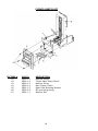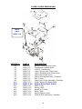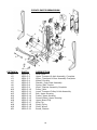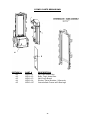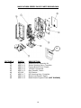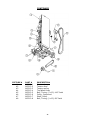
1
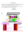
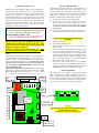
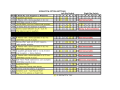
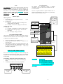
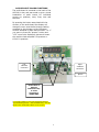
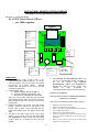
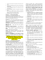
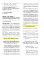
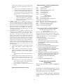
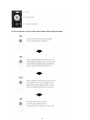
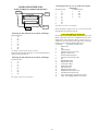
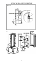
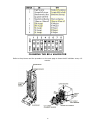
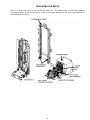
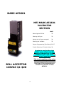
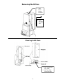
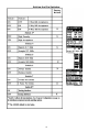
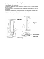
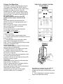
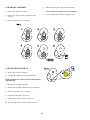
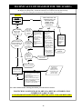
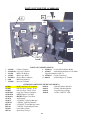
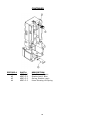
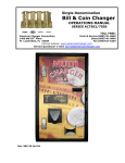
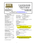
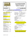
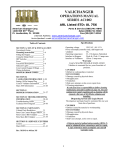
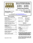
VALICHANGER
OPERATIONS MANUAL
SERIES AC6000/6001/6003
American Changer Corp
1400 NW 65TH Place
Ft. Lauderdale, FL 33309
Parts & Service:(888)741-9840
Sales:(800)741-9840
Fax:(954)917-5204
Internet Address: www.americanchanger.com
Service Questions? [email protected]
Rev. DBCG-1-A Jan’04
1
Attention Please:
American Changer is now building in a Surge Suppressor on every main logic board made after
September 1st, 1998. This will help eliminate power related noise problems for our customers. It will
not protect you from large voltage spikes or lightning strikes over 150VAC.
If this is a concern for your area of business, we recommend purchasing a surge protector locally
NOTE: A POWER STRIP IS NOT A SURGE PROTECTOR.
Thank You,
American Changer Corp
(888) 741-9840
MAIN LOGIC BOARD (ON SIDE WALL OF CABINET)
QUICK CODE FAULT DEFINITIONS
BILL METER /
ERROR CODES
DIP
SWITCHES
00101
DUMP
BUTTON
RIGHT HOPPER
ERROR CODE.
LEFT DIGIT
ALWAYS “0”.
IGNORE!
LEFT HOPPER
ERROR CODE.
Press the “DUMP” Button before turning off changer. Match the code to
samples below to find out why the hopper(s) were shut down.
LEFT HOPPER ERRORS
00000
00100
00200
00300
00400
01000
RIGHT HOPPER ERRORS
0 0 0 0 0 - NO ERRORS
0 0 0 0 1 - LOW COIN
0 0 0 0 2 - EXIT WINDOW JAM
0 0 0 0 3 - BAD HOPPER BOARD
00004
- JAMMED
00010
- NO ERRORS
- LOW COIN
- EXIT WINDOW JAM
- BAD HOPPER BOARD
- JAMMED
- JACKPOT PREVENTED
- JACKPOT PREVENTED
IF THE “EMPTY” LED IS LIT, LOOK FOR CODES FOR BOTH HOPPERS TO BE DISPLAYED!
2
Table of Contents
Specifications
Operating voltage
120 VAC +10/-15
%
Power consumpt.(controller only, add hopper and
validator)10w
Operating temperature
32 - 130 degrees Fahrenheit
Interface to Hoppers
24vdc & 12vdc 1.5 amps
max.
Interface to Validators
120vac .5 amps max.
SECTION A: SET-UP & INSTALLATION
Uncrating & Setup
4
Mounting instructions
4
Filling the Hoppers
4
Using the Dump Mode
4
DIP Switches
4-7, 17
Bonus Pay Out Table
5
Hopper Pay out Table
6
Payout sub modes
6-7
Fuse
8
About the hopper/Coin sizes
8
Indicator Lights
8
Hopper Error Codes
2, 8
Audit Board Functions
9
Set-up/Using the optional Printer 10-12
Functional Descriptions
12-13
Wiring definitions
13
Converting AC6000 to MARS
13
Condor coin Mech Programming 13-14
Warranty
CoinCo MAGPRO 00 B & MARS AE2601 Validator
is warranted for two years from date of purchase.
COVERED
¥ Defect in workmanship or material.
NOT COVERED
¥ Damage caused by physical abuse.
¥ Misapplication
¥ Vandalism
¥ End users attempt, on his own to repair item
¥ Cleaning maintenance
SECTION B: VALIDATOR INFORMATION
Mars Validator Setup’s
15
CoinCo Error Codes
15
Clearing a bill jam in the CoinCo 16
Setting the CoinCo dip switches 17
CoinCo Validator information
16-21
Cleaning the CoinCo
20
Clearing a bill jam in the MARS 23
Setting the MARS dip switches 24
Cleaning the MARS
25
MARS error code information
26-27
It is the End User’s responsibility to follow cleaning
maintenance procedure outline on page(s) 20/25.
Any unit coming in for repair requiring only a
cleaning will be charged a flat rate of $65.00 plus
shipping and handling.
Dispensing System and Logic Board
The dispenser and logic board is warranted for one
year from date of purchase.
COVERED
¥ Defects caused by material or workmanship.
NOT COVERED
¥ Damage caused by physical abuse.
¥ Misapplication
¥ Vandalism
¥ End Users attempt, on his own to repair.
SECTION C: COIN HOPPER INFORMATION
UN-Jamming the Coin Hopper
29-31
SECTION D: TROUBLESHOOTING
INFORMATION
Troubleshooting Guide
35
Technical Flow Diagram
36-37
SECTION E: PARTS LISTS
Cabinet Parts Breakdown
Parts Coin Control Hopper MKIV
Parts CoinCo Bill Validator
Parts MARS Bill Validator
38
39
40-43
44-46
MARS Service Centers
CoinCo Service Centers
47-49
50
A Return material authorization number (RMA #)
must be obtained before returning a unit for repair.
A copy of invoices must accompany any and all
warrantee work
Rev. DBCG-1-A Jan’04
3
UNCRATING AND SET-UP
Remove your Series AC6000/1/3 changer from the shipping box.
Open the door. (The T-handles are a screw-in type and therefor,
must be turned at least 10 times counter-clockwise until it opens.)
Inspect for any connectors or components that may have been
dislodged during shipping. The lock and keys for your changer
will be inside the manila envelope along with this manual. To
install the lock, insert the cylinder into the round hole in the
middle of the T-handle and push until it stops. Now turn the key
and lock until you hear it “snap." Turn the key counterclockwise ¼ turn and remove the keys.
NOTE: The only way to get a duplicate set of keys
made is to save the red tag that comes between the
keys. This ID # starts with “ACC ####”.
FILLING THE HOPPERS
When each hoppers has less than 80 - 100 coins left the red
“Empty” LED will light on the front of the changer. If you
have disconnected your LED make sure the orange wire is
going to the terminal on the LED that has the red positive
mark next to it. Whenever the “Empty” LED is “ON” the
validator is disabled and it will no longer accept bills.
1. Turn OFF the power on the main logic board.
2. Pour the coins into the large opening in the funnel on
the top. There must be at least enough coins to cover
the two gold plates at the bottom of the hoppers.
(Somewhere between 160 and 17,000 coins minimum
to maximum.)
3. Turn “ON” the power switch. The “Empty” LED is
now off and the bill validator is ready to accept bills.
Write your Key # here “ACC_____________”.
ALL KEY ORDERS TAKE 4-6 WEEKS!!!
MOUNTING THE AC6000
Remove the bottom door of the AC6000/1/3 and locate the 4mounting holes predrilled into the floor of the base. Using
lag bolts, bolt down the machine to prevent the machine from
being moved, shaken or tipped over.
REFUSAL TO MOUNT THE CHANGER OR NOT USING
ALL 4-MOUNTING HOLES MAY BE DANGEROUS!!!
TEST:
Before permanently installing the changer, do a functional test to
verify that there is no shipping damage to your new changer(s).
Extend the power cord through the hole in the back of the
changer or the bottom and plug it into a grounded 120vac outlet.
The dip switches are already set for a 4 coin per dollar payout of the hoppers, and the Bill validator is ready to accept
$1-$5-$10-$20 dollar bills.
Fill the each hopper with at least 100 coins. On the main logic
board turn the switch on the bottom right corner “ON". (SEE
FIG. 1 ON PG.3) The rocker switch has a “1” and “0” printed
on it. When the “1” is pressed down the changer is “ON”.
MAIN LOGIC BOARD
Figure
DIP
SWITCHES
4.
5.
THE DIP SWITCHES
The AC6000-6001 series changer is capable of dispensing
coins in different pay out modes. Setting the coins out per
dollar is controlled by which Dipswitches turned “ON."
(Refer to figure 1 for their location.) For example, switch #2
is “ON” on both dipswitches; therefor the payout equals 4
coins per dollar. Two coins per hopper for one dollar.
00001
EPRO
M CHIP
T
R
A
N
S
F
O
R
M
E
R
BILL
METER
1.
2.
3.
USING THE DUMP MODE TO EMPTY THE
HOPPERS
Open the cabinet door.
Turn OFF the POWER switch.
Place a suitable container in front of the hoppers to
catch the coins.
Press and hold the “DUMP” button on the upper right
corner of the Main Logic Board. Turn ON the Power
switch. The red LED numbers on the main logic board
will come on all “88888’s” then go all “00000’s”. Once
the red “00000’s” light up, release the “DUMP” button.
If it is not released within two seconds, the “DUMP”
mode is canceled as a security feature.
The hoppers will dispense coins until the POWER
switch is turned OFF. If the red LED numbers are not
counting up rapidly on the Main Logic Board’s display
the dump mode was not accessed. Please try again.
DUMP
SWT.
1
ON
1
PRIMARY
2 1/2 AMP
FUSE
2
3
4
5 6
7
8
VALIDATOR
CONNECTORS
HOPPERS
HARNESS
CONNECTORS
FIGURE 2
(THIS IS NOT THE DIPSWITCH BANK FOR SETTING
THE BILL DENOMINATIONS.
(For those dip switches go to pages 18-19.)
1
0
ON/OFF
SWITCH
AC LINE
CORD INPUT
4
5
6
HOW TO USE THE BONUS TABLE
Think of the bonus table as the total amount of EXTRA tokens
after the regular payout, that you wish to receive:
EXAMPLE: PAYOUT: 4 tokens for $1, 24 for a $5, 52 for a $10,
120 for a $20.
24 tokens = $1 extra in tokens
52 tokens = $3 extra in tokens
120 tkns = $10 extra in tokens.
Now go to the bonus table, find where the $5 column =$1
Look over to the $10 and go down until you see $3.
Finally go to the $20 column to where = $10.
You should be at 1-3-7; Turn “ON” your right dipswitches 1-3-7
to set this payout.
DIPSWITCHES
The following table shows how to set the dip switches to your
desired payout.
“ON”
COINS PER DOLLAR
#1
1
#2
2
#3
4
#4
8
The left dipswitch controls the left hopper’s pay out and the
right dipswitch controls the right hopper’s pay out.
Refer to the next table to set up your changer for the settings you
need.
MODE DESCRIPTIONS
Some of the modes are self-explanatory while others have
sub modes built into the chip. Here is a list of the modes
and sub modes when applicable.
MODE 2 - $1 coins the balance in quarters:
The quarters for each bill are controlled by the sub mode
settings of the right dipswitches #1 & #2.
Neither “ON” – 16 Quarters balance in $1 coins.
#1 “ON” only – 8 Quarters balance in $1 coins.
#2 “ON” only – 12 Quarters balance in $1 coins.
#1 & #2 “ON” – 4 Quarters balance in $1 coins.
MODES’ #5 & #11 – Setting right dips in “$1
increments”:
Refer to Page 6 Under “Dipswitches Con’t”. But instead of
counting up in coins, think of it as dollars.
Another way to look at the Bonus pay out
mode is as follows:
The bonus is paid out by the amount of tokens given for a
dollar. For the below explanation we will say you are giving
4 tokens per dollar. Left dips #3-#6-#7 is ON.
Right DipSwitch
For a $5.00 bonus payout:
#1
#2
20 tokens + no bonus
OFF OFF
20 tokens + 4 extra tokens
ON OFF
20 tokens + 8 extra tokens
OFF ON
20 tokens + 12 extra tokens
ON
ON
For the $10.00 bonus pay first double the pay out for the $5
bill. So if the total tokens given for the $5 bill was 24, the
pay out for the $10 bill is 48 tokens. Now let’s figure out the
bonus for the $10 bill.
Right DipSwitch
For a $10.00 bonus payout:
#3
#4
$5 pay out + no bonus
OFF OFF
$5 pay out + 4 extra tokens
ON OFF
$5 pay out + 8 extra tokens
OFF ON
$5 pay out + 12 extra tokens
ON
ON
Right DipSwitch
For a $20.00 bonus payout:
#5
#6
#7
$10 pay out + no bonus
OFF OFF OFF
$10 pay out + 4 extra tokens
ON OFF OFF
$10 pay out + 8 extra tokens
OFF ON
OFF
$10 pay out + 12 extra tokens ON
ON
OFF
$10 pay out + 16 extra tokens ON
OFF ON
$10 pay out + 20 extra tokens OFF ON
ON
$10 pay out + 24 extra tokens
ON
ON
ON
The following table shows how to set the dip switches to
your desired payout.
“ON”
COINS PER DOLLAR
#1
1
#2
2
#3
4
#4
8
If you want to dispense 5 dimes and 2 quarters per dollar turn
“ON” switches #2 on the left and #1and #3 on the right dip
switch. (2 quarters + 5 dimes = $1.00)
The left DipSwitch controls the left hopper’s pay out and
the right DipSwitch controls the right hopper’s pay out.
Refer to the next table to set up your changer for the settings
you need.
MODE #14 – Canadian $1 &$2 coin payout:
The right dipswitches #1 & #2 can alter the amount of $1
coins given to each denomination.
Luni’s per $
$5
$10
$20
Neither “ON” - 1L
0L
0L
#1 “ON”
3L
2L
2L
#2 “ON”
3L
4L
4L
The machine will always give 2 Luni’s for a Tuni.
7
FUSE
Coin/Token Sizes
Low voltage fuse: This is the secondary transformer fuse for the
5 - 28 VDC sections of the main logic board and hoppers. It is
located to the left of the transformer. (See fig. 1) Replace this
fuse with a 2-½ amp AS fuse only. REPLACING THIS FUSE
WITH ANYTHING OTHER THAN A 2 ½ AMP “AS” MAY
RESULT IN A FIRE OR AN UNSAFE WORKING
CONDITION!!
Indicator Lights
Main Logic Board:
1. Green LED on: AC power applied to the logic
board.
All fuses are good.
2. Decimal Point:
A. Heartbeat - 5 and 12vdc present. The changer is in
standby waiting for a bill pulse.
B. On Steady - Out of service, Hopper error detected.
Validator logic board:
1. Red LED
A. On Steady - Standby Mode, waiting for bill insertion.
B. Flashing - Error mode, go to page for error code
information.
C. Off - The changer “Empty” LED is lit.
The hoppers will automatically adjust to dispense
coins/tokens in size from 20-30 mm in diameter and 1.25 3.5 mm in thickness.
There is an option available to dispense smaller coins. A
nickel is approximately 21 mm, a quarter is approximately
25mm. A Susan B. Anthony is 28mm
Hopper coin
bin. (Dump
the coins into
this hole.
1600 coins
max.)
Coin counting
LED.
Security LED.
(all systems OK)
12vdc Power LED.
Coin counting optic.
Coin Control Hopper MKIV
Three green LED indicators are fitted on the hoppers and are
visible in the section where the coins exit the hoppers. From left
to right these are designated as follows:
1.
2.
3.
Logic power supply on (12 & 24vdc present).
Security optical obstruction indicator -. Should be ”on”
when unit is OK.
Output indicator, indicates coin passing photo-sensor. This
is the optical sensor the coin will obstruct on its way out of
the hoppers. For normal operation LED # 3 will be off
until coins are dispensed.
LOGIC BOARD ERROR CODES
We now have the ability to display error codes in dealing with
the problems associated with the changer. There are 2 different
locations error codes can be displayed depending on the source
of the problem.
If the “Empty” LED on the outside of the changer is lit:
1. Press and hold in the “Dump” button on the main logic
board.
2. The display now shows the code for your problem.
Bill Meter Display
0 0 0 0 0
Left Hopper
Codes
12 pin male
connector.
(located on the
opposite side.)
Motor
The right & left hopper has a
removable coin chute installed.
Replacement hoppers are not
sent with this coin chute.
Left chute P# AC2010-104 &
Right chute P# AC2010-114
Error Codes:
01 = Low Coin
02 = Coin exit window is blocked
04 = Under-payment was detected
10 = Over-payment was detected and
Prevented. (Jackpot condition)
A “03” error code is a low coin and exit blocked in the
same hopper.
Right Hopper
Codes
8
AC6065 AUDIT BOARD FUNCTIONS
The audit board is mounted to the back of the
AC6000/1 door and was made to give a visual
breakdown of audit counts for individual
counts on: quarters, ones, fives, tens and
twenties.
By pressing the button associated with the
counter on the audit board the display will
change from an exact dollar/change reading
accepted by the changer to the individual
counter accepted by each denomination. I.e. if
you were to press the “quarter” button and
“132” were to be displayed, that would mean
the machine had accepted 132 quarters or
$33.00 in quarters.
Left
Validator
Connector
Right
Validator
Connector
Eprom
Press these 2
buttons
simultaneously
to reset
counters to
“$0000.000”
To reset the counters to zero press and release the two
outside buttons (quarters + $20) simultaneously. After the
NEXT bill is inserted the counter is reset to zero!
9
THE (AC7070) PRINTER OPTION UPGRADE
Installation & programming instructions
SECTION A. – General Information
All AC7070 Printer Boards (PB) are
year 2000 compliant.
Figure 1
American
Machine
##
Sequence #
Printer
With
Paper
Option
Buttons
#1-#4
Top
Connector
#3
A
8
9
Bottom
Connector
#2
Battery
2-Year Shelf
life
Ribbon
Connector
#1
FAST FACTS:
1. Replace battery every 2-years with a 3VLithium #CR2320, Positive side UP. It is a very
common battery and can be found just about
everywhere, even Radio Shack.
Replace
battery with the power on so not to lose the
existing programming.
2. Replace paper with:
A. Nippon TP50KS-E2C or TP50KS-A
B. Honshu FH65BU-2 or FH65BX-14N
C. Mitsubishi F-200U9W3 or F-200U7N5
Using any other paper than the type specified
will dramatically cut down the life of the printer.
Office Depot should carry at least one of these
paper types..
3. Change the paper with power on at the printer
board. Feed the paper into the back of the
printer until it stops. Press and hold the #3
paper feed button until the paper comes into
view.
4. The dial in the lower right corner of the print
board is to set print contrast. DO NOT MAKE
THE CONTRAST to dark. It will cause the print
head to burn up. It should be set to be just
legible.
5.
Logic
EPROM
Ver.B-06
Print
Contrast
Adj. Dial
THE PRINTER IS MAINTENANCE FREE!!! Do
not try to mechanically adjust, lubricate or
pry
on
the
printer.
ANY
PRINTER
MAINTENANCE VOIDS THE WARRANTY!!!
Blowing the dust out of the printer with
canned
air
every
6-monthes
is
recommended and required by the warranty.
SECTION B. – Installation
INSTALLATION OF THE AC7070 PRINTER BOARD ON
INDIVIDUAL MACHINES.
If the Printer was installed at the factory skip to Section C
1.
2.
3.
4.
5.
6.
10
Remove power from the machine.
Remove the hoppers from the machine.
Remove the hopper plates and disconnect the harnesses
from the Main Logic Board.
Remove the original validator harness.
Install the new plates and connect the harnesses to the
Main Logic Board. (Right plate to the bottom hopper
connector.)
Make sure the inside left wall of the AC2000 series
cabinet is free of dirt and oil.
machine is number “000”. Follow the directions
on the printout. Every time you press the #
button the red light will flash and the digit
associated with that digit counts up by one. DO
NOT RUSH!!! IF YOU DID NOT SEE THE RED
LIGHT ON THE PRINTER BOARD FLASH YOU
COUNT DID NOT INCREMENT!!! If you made a
mistake, press OK (#4), then #2 to restart the
operation. For a sample we’ll assign #358 as
our machine number.
1. Press the #1 button 3 times to set the
“hundred’s” digit.. (Try to press once per
second. This is a good rhythm. Ensure the
red light on the printer board also flashed
three times.)
2. Press the #2 button five times to set the
“ten’s” digit.
3. Press the #3 button 8 times to set the
“one’s” digit.
4. Press #4 OK. (If the printer does not show
the desired machine number press#2, and
go back to step #1)
5. Press #4.
The printer will now print a receipt showing the
new machine number at the top of the paper.
7.
Peel the covers off the 4 stick pads at each corner of the
board.
8. Attach the board firmly onto the side of the cabinet by
pressing firmly in each of the Four Corners of the board
simultaneously.
9. Connect the RIBBON CABLE to the AC2000 series on the
Printer Board.
10. Attach the RIBBON CABLE to the pigtails of the hopper
plates.
11. Attach the new validator harness. Connect it to the lower
plug on the Main Logic board, the Empty LED, and to the
Bottom Connector #2 on the Printer Board.
12. Reinstall the hoppers onto the hopper plates.
Section C. – Printout Description.
DESCRIPTION OF THE PRINTER’S PRINT-OUT
When you first receive your Printer, you will see a
printout on the tape sticking out of the Printer.
Below is the description line by line:
Machine # - This will be programmed by the user
later. It is the programmable number designation
assigned for this machine.
Sequence # - This is the audit number assigned to
the receipt. The printer will print out 2 receipts per
sequence.
Date & Time – Date and time the printout
occurred.
Quarters through Hundreds – The amount of
each currency accepted since the printer was last
reset.
Sum – The amount in dollars the printer has
accumulated since it was last reset.
Total – The amount in dollars the printer has
accumulated in it’s lifetime.
THIS TOTAL CAN
NEVER BE RESET!!!
Hopper 1 & Hopper 2 – The amount of coins
given out of each hopper since the printer was last
reset. In a 1-hopper machine only, Hopper 1 will
accumulate.
Time – Reenter the program mode and this
time press #2 for the 24-hour clock. In the
sample below I will use 9:52 AM. (For those of
you unfamiliar with this type of time setting here
is a sample. 1:00 AM = 0100 hours, Noon =
1200 hours, 1:00 PM = 1300 hours, 6:00 PM =
1800 hours, Midnight = 0000 hours.)
1. Press #3 for the TENS setting on the 24hour clock. (Since the sample time is 9:52
AM or 0952 hours DO NOT PRESS#3. Just
hit #4 to move on.)
2. Press #3 9 times to set the hour, then press
#4.
3. Press #3 5 times to set the hour, then press
#4.
4. Press #3 2 times to set the hour, then press
#4.
5. Press #4 OK. (If the printer does not show
the desired machine number press#2, and
go back to step #1) .
6. Press #4.
The printer will now print a receipt showing the
new time at the top of the paper.
THE DENOMINATIONS AT THE BOTTOM
OF THE PRINTOUT REPRESENT THE LAST
3 BILLS ACCEPTED BY THE BILL
ACCEPTOR(S).
Section D. – Programming the Printer.
How to Program the AC7070 Printer Option
There are 4 programming modes associated with
the Printer: Machine #, Time, Date, and the ability
to make the “SUM” on the printer printout resetable
or non-resetable.
To enter the programming mode, turn the main
logic board of the machine off. Press and hold
down the #2 & #3 while turning on power to the
main logic board.
Release the #2 & #3
pushbuttons as soon as the printer head move,
(Approx. 1 second)..
The Printer prints out
“****Set up Mode****” and you’re ready to start!
Now that we’re in the set up mode let’s press #1 to
set machine number. This number represents this
machine. This way if you have multiple printers
and receipts scattered on your desk, the machine
number will tell you which machine the receipt is
for. This number has three digits. Right now the
Date – Reenter the program mode. The sample
will be May 15th 2000.
1. Press #3 for the date mode.
2. Press #2 for 2000 then press enter.
3. The printout shows 2000, if it is correct
press #4.
4. Press #4 for the “ten’s” digit of the year.
5. Press #3 to set the “one’s” digit of the year.
For the example press #3 2 times.
6. The printer now shows the completed year.,
if it is correct press #4.
7. To set the month “ten’s” digit press #3. In
the example the month is ‘05’ so press #4 .
11
8.
Set the “one’s” digit of the month, in the
example press #3 5 times. Press#4.
9. Press #4 if printout matches the month.
10. Set the “ten’s” digit of the date by pressing #3.
11. Press #3 to set the “one’s” digit of the date.
12. Press #4 if date printout is correct.
The printer will now print a receipt showing the new
date at the top of the paper.
Resetable Counter – This feature either locks the
“Sum” total on the printout, or allows it to be reset
each time you increment the sequence number.
1. Enter the program mode.
2. Press #4.
3. Locked – YES or NO.
The printer will now print a receipt.
4.
5.
6.
Section E. – Printer Operation
The Printer operation is fairly simplistic. The Printer
gets its input pulses from the bill validator and sorts
them into the categories such as “quarters” and
“twenties”. For the “hopper” category, each hopper
‘s exit window is monitored and each coin is
counted as it’s dispensed.
7.
8.
Using the Printer – Once installed the printer
should be used as any normal accounting device.
THE PRINTER WILL NOT LOSE ANY ACCOUNTING
INFORMATION WHEN POWER IS LOST! A printout
can be obtained by pressing the “PRINT” (#2)
button. This action will not reset the accounting
features. It is a monitoring printout only! Another
helpful feature of the Printer is the printout of the
last 3 bills entered. This feature was installed to
double check customers that say they lost money in
the machine.
NOTE: THE METER ON THE MAIN LOGIC BOARD
CANNOT BE RESET TO ZERO!!!
Functional Descriptions of Out-of-Service Conditions
Out-of-Service conditions occur for the Series AC6000-6002
changer for the following reasons: low coins, hopper fault
error, validator fault, or a blown fuse.
Every accounting period the Printer will need to
dump it’s information and start over.
This is
accomplished by pressing the #1 and #4 buttons
simultaneously.
The printout will have *Reset
Count Receipt* at the top. There are 2 receipts
printed, then the counters are reset to 0.
1.
THE “TOTAL” COUNT CAN NEVER BE RESET!!!
(End Printer Description Section)
Functional Description of the Series AC6000-6003 Changer
To follow along with this walk-through of your changer, fill the
hoppers with coins and turn the changer on.
1.
2.
3.
bill looks like to its memory. After the bill is validated it
grounds the 5vdc lines causing a pulse along the yellow
and blue validator harness wires to pins 5 and 15 of the
main logic board. Each pulse stands for the amount of
the denomination validated. (i.e. 1 pulse for $1, 5 pulses
for $5).
The 5vdc pulse then travels from pins 5 and 15 to the
EPROM chip (DBCG-1) pin #25. The EPROM sends a
12vdc pulse to the meter chip (U5) out pins #21
& 22 (one pulse per denomination validated ).The
EPROM also multiplies the bill pulse by the DipSwitch
settings (The EPROM reads the DipSwitch settings
during the power up mode and stores them into
memory.)
The EPROM then sends the hopper pulses out pin #23
to pins 6 and 7 of the red 12 pin hopper plugs. These
pulses travel through the purple and brown wires of the
hoppers wire harness to the hoppers pins 8 and 12.
The hopper turns itself on with the first hopper pulse.
The hoppers counts the hoppers pulses sent from the
EPROM chip on IN3 (pin 12) while dispensing the coins
at the same time. When the amount of hoppers pulses in
equals the coins dispensed through the coin counting
optical sensor the hopper turns itself off.
The Changer returns to the standby mode with the
decimal point flashing once per second until another bill
is inserted.
2.
When power is applied the validator will cycle twice, the
out-of-service LED flashes then goes out, the green LED on
the main logic board comes on steady, and the decimal point
on the main logic board number display will flicker on once
per second in the standby mode.
During the power-up mode the main logic board relay clicks
twice enabling power (120vac) to the validator. When this
relay is not enabled it routes 12vdc ground to the out-ofservice LED. Without power to the validator the changer
cannot accept bills. Since we are not in the error mode, the
red LED on the validator logic board is on steady.
When a bill is inserted into the validator bill slot, the bill
will be pulled inside. The validator then compares what the
12
Blown Fuse: an AC power spike in line voltage or a bad
transformer on the main logic board can cause A blown
fuse on the main logic board. If either fuse blows the
indication is the green LED on the main logic board will
not light.
A. Replace the fuse. If the green LED now lights then
there was a spike.
B. If it does not and the fuse blows again the power
transformer is shorted. To test the transformer use a
voltmeter set for ohms and measure across the
primary (40ohms) and the secondary (1.5ohms).
Hopper Fault: A hopper fault can either be a jammed
hopper, a blocked coin counting optic or a bad hopper
logic board.
A. Indications for a jammed hopper are the changer
accepts bills, the meter counts up, but nothing or
not enough coins are paid out.
1. After 2 minutes the EPROM shuts off the
validator if the coins are not paid out
correctly. The “Empty” LED will flash once
per second.
2. At this point the three options open are to
attempt repair on your own, call your
distributor, or return the defective hopper to
American Changer.
B. Indications for a blocked coin optic or bad hopper
logic board are the out-of-service LED on the
3.
4.
outside of the changer is lit and the red LED on the
main logic board is lit and flickers off once per
second.
1. If two of the 3 green LED’s on hopper logic
board are lit then the hopper logic board is bad.
2. If there is a coin or foreign object caught in the
coin exit window LED’s #1 and #3 will be lit on
the hopper logic board instead of LED’s #1 and
#2.
a. Take off the side of the hopper with the 5
Philips screws. Pull up on the exit window
logic board and look for the jammed item.
b. Ensure you have the pins aligned before
reconnecting logic board.
Validator Fault: When a validator fault occurs the
validator’s EPROM shuts down the validator and flashes an
error code via the red LED on the validator logic board.
When there is no error this LED is on steady. The validator
only gives bill pulses to the main logic board so the main
board never knows if the validator isn’t functioning.
Therefore the out-of-service-LED will not light. (See page
7 for validator error codes.)
Low Coins: The low coin condition is probably the most
common fault. The EPROM on the main logic board is
constantly checking for low coins in the hoppers. This is
done with a low current 5vdc signal on pin #3 of the
hopper’s output connector. The voltage then travels down
the hopper’s wire harness on the white wire to pin #7 of
hopper’s plug. The signal is applied to one of the gold low
contact plates at the bottom of the hoppers. The 5v travels
through the coins through the other contact gold plate to
hopper’s pin #2. It then goes through the black wire in the
hopper’s harness to pin #10 on the main logic board. Any
interruption of more than 1/2 a second will cause an out-ofservice condition.
A. Clean the bottom gold plates of the hoppers with steel
wool or fine sandpaper. Refill the hoppers and try
again.
B. Check continuity, (0 ohms) resistance, from pins 3
(white) and 10 (black) of the red hopper harnesses.
Make sure both hoppers are full and the changer is
turned off.
1. If the continuity is 0 ohms, replace the main logic
board.
C. Pull the hoppers out of the changer, then look at the 12
pin black male connector that sticks out of the
hoppers. Place the continuity checker’s leads on pins
2 & 7.
1. If the continuity is 0 ohms, replace that hopper’s
plate or adjust the hopper’s plate female socket’s
pins so that they are not so spread out.
2. If the continuity is infinity, then replace that
hopper.
WIRE HARNESS COLOR AND DEFINITIONS
Validator harness:
Switched Hot 120VAC.
Neutral 120VAC.
120VAC Low current validator enable.
+5vdc credit pulse line.
-5vdc credit pulse line.
+12vdc Empty LED.
-12vdc Empty LED.
Hopper Harness
Gray - Coin counting optic status line.
White - Low coin sense (+5vdc).
Green - Coin counting optic pay out feedback line.
Yellow - Raw sensor output line.
Purple - Hopper pay out line from main logic board (+),
Brown - Hopper pay out line from main logic board (-).
Red +12vdc logic board supply voltage.
Black(s) -12v, 24v low coin sense ground.
Orange - +24vdc Motor supply voltage.
Red White Black Yellow Blue Orange Brown -
Converting CoinCo to MARS AE2601’s
Machines made after September 2002
(Serial # 02366-------)
To convert these machines first ensure the correct
harnesses have been ordered. (Part # AC1061.1-4H =
Validator Left Harness, AC2062.1-2H + AC2066.3-1H
= Right Validator Harness + Condor Coin Mech
Adapter (if required)).
1. Remove Power & the Factory Harnesses.
2. Remove the CoinCo’s.
3. Loosen the 4 nuts on the door & slide the right
side door validator bracket to the lowest position
then retighten.
4. Install Right MARS Validator.
5. On the left side folding validator bracket, flip the
bracket forward & remove the 2 adjustment
screws from behind. Place the bracket on its lower
setting and re-install the screws and tighten.
6. Install the left MARS.
7. Install both wire harnesses. Ensure you plug the
Door Mars validator to the left side Audit or TOP
printer connection and the Flip bracket Mars to
the right side Audit or BOTTOM printer
connection.
8. Set page 24 to set the DipSwitches.
Condor Electronic Coin Mech.
Programming
The next page will teach you how to program the
Condor.
(End Functional Descriptions Section)
If you have an AC6000 Program the $1 coin in
the #1 Slot. You can not accept Quarters and
dollar coins with out a new wire harness.
If you have a AC6001 or AC6003, program the
Quarter into the #1 slot and the dollar coin in the
#4 slot.
13
14
Interfacing the Mars AL-4 or AL-4 Plus Series with the
ValiChanger
8-Position Switch
4-Position Switch
1
on
1
off
2
off
2
off
3
on
3
off
4
on
4
off
5
on
6
off
7
off
8
on
The 18-pin connector is not required.
VALIDATOR INTERFACES
18 PIN INTERFACE CONNECTOR DETAILS
Pin #1
PLUG KEY
Pin #10
Pin #9
Pin #18
Ensure the black & yellow wires go to a wire nut and the
green & white go to the other wire nut
Interfacing the Mars 2501/2511 Series with the ValiChanger
8-Position Switch
1
off
2
on
3
off
4
on
5
off
6
on
7
off
8
off
No change is required to the 18-pin connector..
Ensure the black & yellow wires go to a wire nut and the green &
white go to the other wire nut
CoinCo MAGPRO Series Flash Codes
Flash codes 1-18 may appear during normal servicing of the
BA30. If more than one error or condition exists, the lower
number flash code will appear until its respective error or
condition is corrected. The left and right sensors referenced
below are given viewing the BA30 from the front.
# of Flashes
Description of Flash Codes
1
Bill box full
2
N/A
3
Check bill path
4
All bill accept switches are off
5
Bill jam or sensor error
6
Stacker motor/home sensor
7
Transport motor/encoder sensor
8
N/A
9
EPROM Has Failed
10
EPROM Has Failed
11
Center Optic Failed
12
Right Optic Failed
13
Left Optic Failed
14
Bill Position Sensor Error
15
Right Bill Position Sensor Error
16
Left Bill Position Sensor Error
17
Lower Anti-Stringing Armature out of place
18
Upper Anti-Stringing Armature out of place
Interfacing the Mars 2601/2611 Series with the ValiChanger
8-Position Switch
1
on
2
on
3
on
4
on
5
off
6
on
7
off
8
off
The 18-pin connector is not required.
15
COINCO MAG50B
VALIDATOR
SECTION
PAGE
16
Removing the Bill Box
17
Clearing a bill jam
17
Setting the bill types accepted
18-19
Cleaning the sensors
19-20
Cleaning a salted unit
20
Replacing the belts
21
Removing the bill box.
To remove the 1000 bill stacker from the CoinCo validator follow the picture below.
REMOVING A BILL JAM
From time to time a foreign object or ripped bill will become caught in the validator. Follow the
picture below to remove the item.
17
SETTING THE BILL ACCEPT DIP SWITCHES
18
CLEANING THE BILL VALIDATOR
Refer to the pictures and the procedure on the next page to clean the bill validator every 4-6
months.
19
MAGPRO CLEANING: IF ANY OF THESE PROCEDURES ARE PERFORMED TO YOUR VALIDATOR AFTER IT IS
RETURNED UNDER A WARRANTY REPLACEMENT, YOU WILL BE SUBJECTED TO A $65.00 LABOR FEE.
CLEANING AND MAINTENANCE:
Note: Petroleum-based cleaners and freon-based propellants can damage plastic and some electronic components.
Scouring pads and stiff brushes may harm the protective conformal coating on the circuit boards and can mar the
plastic.
These
items
should
never
be
used
when
cleaning
the
MAGPRO
bill
acceptor.
5. Remove the bottom cover from the lower
The MAGPRO should be cleaned every 7,000 bills
housing.
or every 4 -6 months (or as needed, depending
6. Run hot water (1101/4-1401/4F) over the lower
on the environmental conditions of the
housing from the top and bottom. Using a soft
location). Dust can be removed with a soft
brush, gently clean any residual salt. Use a soft
brush or cloth or it can be blown out using
absorbent cloth to clean any residue off the lower
compressed air.
housing. If the transformer gets wet, allow the
Procedure:
unit to dry for 24 hours before applying power.
1. Disconnect power from the bill acceptor.
7. Remove the front mask. Using hot water and a
2. Remove the bill box and use a soft cloth to wipe
soft brush, clean the front mask, upper sensor
the dust from around the intermediate frame and
board, main frame anti-pullback levers and
stacker plate.
position sensor mount.
3. Remove the lower track.
Caution: The motors are not protected from water,
4. Using compressed air or a soft brush, blow or
therefore the unit must be held in a manner that
brush the dust off of the optic sensors and out of the
prevents water from running over the intermediate
recessed sensor openings.
frame crossbar.
5. Remove dust from around the belts and wheels on
8. Remove the position sensor cover on the crossbar
the lower housing and the sensors on the upper
and carefully lift the LED from its mount. (Early
sensor board. The upper sensors are located directly
models only.)
above the lower housing sensor when the lower
Caution: Protective coating on the LED leads should
housing is installed.
not be damaged. Clean all salt residue from the
6. The bill path can be cleaned to remove further dirt
mount, sensor hole and detector area.
and oil using a soft cloth moistened with a mild soap
The detector can be seen through the sensor hole,
and water solution.
and is located in the chassis. Replace the position
7.
Clean the magnetic head using a swab and
sensor cover. (Early models only.)
isopropyl alcohol.
9. Verify that the anti-pullback levers move freely
8. Once the lower housing is dry, place it back into
and that the spring returns them to their open
the mainframe so that the tab on the bottom locks
position.
into place.
10. Allow the unit to dry thoroughly.
9. Blow the dust out of the encoder wheel and its
11. Clean the magnetic head using a swab and
sensors. (It may be necessary to extend the stacker
isopropyl alcohol.
plate to access the encoder wheel. Supplying power
12. Replace the front mask
to the unit momentarily can do this, so that the
13. Replace the lower housing cover.
stacker plate extends.)
14. Replace the lower housing into the main frame.
10. Remove dust from the transport belt areas and
15. Remount the bill box.
from any other places of build up.
16. Apply power and insert bills to verify that the unit
11. Remount the bill box.
is functioning properly.
12. Apply power and insert bills to verify that the unit
6 OR 7 ERROR CODE FLASHES
is functions property.
The cleaning procedure for this common occurrence is
listed below. Just follow these steps.
MAGPRO CLEANING PROCEDURE FOR SALT
1. If this code has occurred on a new machine or
WATER POLLUTED UNITS:
one that the validators DIP switches were just
Note: Petroleum-based cleaners and freon-based
changed, Ensure that all the white plugs on the
propellants can damage plastic and some electronic
side of the validator board away from the red LED
components. Scouring pads and stiff brushes may
are plugged in securely.
harm the protective conformal coating on the circuit
2.
Remove the bill box.
boards and can mar the plastic. These items should
3. Turn the Changer ON then OFF in an attempt to
never be used when cleaning the BA30 bill acceptor.
stop the metal push plate so that it COASTS into
Procedure:
the fully outward position.
1. Remove power from the bill acceptor.
4. Using an air compressor or a can of compressed
2. Remove the bill acceptor from the vending
air blow out the area behind the push plate until
machine.
it is completely free of all dust and lint.
3. Open the bill box lid and verify that the stacker
5. Turn the changer power back on so that the push
plate is in the stand-by/home position. If it is not
plate returns to the inward position. If the same
in the home position, apply power and observe
error code persists, repeat steps 1 - 3
that the stacker plate returns home.
concentrating on the top center area behind the
Warning: If moisture is present, allow the unit to dry
plate.
thoroughly before applying power to avoid possible
6. Replace the bill box.
shock hazard. If the stacker plate does not return to
the home position, remove power and carefully
remove the bill box to avoid damaging the bill box
and/or stacker plate.
4. Remove the lower housing.
20
REPLACING THE BELTS
Every 2-3 years the belts on the CoinCo will wear out. To replace them, remove the validator
components down to the picture show. Refer to the parts diagram at the end of the manual for
help getting to this point.
21
MARS AE2601
MEI MARS AE2601
VALIDATOR
SECTION
PAGE
Removing the Bill Box
23
Clearing a bill jam
23
Setting the bill types accepted
24
Cleaning the Validator
25
Coupon Programming (Dip Switch) 26-27
Trouble Shooting & Trouble Codes 28
In order to use the Mars type
VN2611 type validator the door
must be changed out to the
“UNIVERSAL style” with the large
cut out openings.
This is not a problem when using
the Mars VN2601 style validator!
BILL ACCEPTOR
120VAC $1-$20
See Page 13 for instructions to
convert from CoinCo to Mars
AE2601.
22
Removing the bill box
2. Push
BLUE
button
forward.
1. Push
bill box
up and
out.
Clearing A Bill Jam
1. Pull up on silver
bar (Rod)
2. Pull bar away
from the Mars.
23
Setting the Dip Switches
24
Cleaning & Maintenance
Cleaning
You can clean the bill acceptor while it is still mounted in the machine.
1. Remove power from the machine.
2. Unlatch the magazine by pushing the blue latch (located on the top of the unit) toward
the front of the unit.
3. Unhook and remove the magazine by holding the latch and lifting up and then back on
the magazine.
4. Unlatch the LED Housing by lifting up on the metal bar (located below the Status LED).
5. Remove the LED Housing by holding the metal bar and pulling back on the LED
Housing.
6. Clean the bill path with a soft cloth. You may use mild, non-abrasive, non-petroleum
based cleaners if sprayed on the cloth.
25
Coupon Configuration
THIS IS NOT A USABLE COUPON!
DO NOT COPY!!!
FIGURE 1
The AE2601 may be configured using a coupon.
The coupon is included in the AE2601 Series
Installation Guide. Carefully cut the coupon along
the dotted-line edge to remove it from the
installation guide. Copies of the original coupon
may be produced with a standard, carbon-based,
non-color copier. Cut copies to match the size of
the original coupon.
All option switches must be in the OFF
position for the coupon selections to be
active.
The coupon selection will remain with the
AE2601 until the unit is reprogrammed, even if
power is removed.
When filling out the coupon, note the following:
Use only a #2 pencil to fill in the blocks
Fill in the entire block
Do not mark the coupon outside the blocks
or on the back of the coupon
Fill in ONE block for EVERY line
Coupon Programming
1. Fill out the coupon using the table below.
2. Locate the service button on the back of the unit
(refer to Figure 2).
3. Press the button once to enter the coupon
setup mode. Pressing again will exit the
mode. The unit will automatically exit coupon setup
mode upon acceptance of the
coupon configuration.
The LED Status indicator (located to the left of the
service button) will flash rapidly
indicating that the unit is in coupon setup mode.
4. Insert the coupon marked-side up.
The AE2601 will pull the coupon in, read it, and
then return it to the user.
A good coupon will be returned immediately. After
the coupon is pulled from the bill
acceptor mouth, the unit will flash the Status LED
ten times to confirm a good
configuration.
A bad coupon will be held for ten seconds before
being returned. This delay is to
make you aware that there is a problem with the
coupon. When the coupon is pulled
from the bill acceptor mouth, the unit will flash the
Status LED the number of times
corresponding to the section of the coupon
wherein a problem lies. For example, if
26
FIGURE 2
the problem is in section five, the LED will
flash five times. Section numbers are
located to the far right of each section on the
coupon.
5. If the configuration is rejected, check the
coupon and repeat the process.
Trouble Codes
3 Flashes - Indicates that the bill path
needs cleaning for optimum performance.
Remove the magazine and LED housing and
follow cleaning instructions (page 29) to
clean the bill path.
Status LED
A Status LED provides assistance in diagnosing
the condition of the Series AE2600. The
following is a description of the LED codes,
their meanings, and suggested remedial
actions.
4 Flashes - Indicates that something is
obstructing the bill path.
Remove the LED housing and look at the bill
path on the housing and inside the unit for
foreign material; clean as necessary.
LED ON - Indicates that the unit is enabled
and ready to accept a bill.
No action is necessary.
LED OFF - Indicates that no power has been
applied to the unit.
Check to ensure that power is applied.
5 Flashes - Indicates that the magazine is
removed (the unit will not accept without
the magazine attached).
Reinstall the magazine.
1 Flash - Indicates that something is
obstructing the bill path.
Remove the magazine and LED housing.
Inspect for foreign material.
Continuous Slow - Unit is defective.
Replace the unit.
Continuous Fast - The magazine is full of
money.
Remove the money from the magazine.
2 Flashes - Indicates that the unit is not
enabled.
Verify configuration. Check the dipswitches.
27
MKIV UNIVERSAL
HOPPER
INDEX
PAGE
1. Coin box removal & reassemble
29-31
2. Exit window replacement
30
3. Logic board replacement
31
4. End plate removal
31
5. Track plate removal
32
5a. Track plate assembly
32
5b. Track plate replacement
33
5c. Final drive gear replacement
33
6. Gearbox assembly
34
7. Motor replacement
34
To un-jam the hopper, refer to sections
4 – 5b, pages 31 –33.
SERVICE MANUAL
28
1. COIN BOX REMOVAL
1.
Place the hopper in front of you as shown, (looking at
the outside of the ‘coin box’).
Refer to FIG 1.
2.
Remove the 2 locking nuts, which hold the ‘low level
sense plate’ wires to the studs.
3.
Remove the crimp & wire from the studs.
ACCESS IS NOW AVAILABLE TO THE ‘LOW
LEVEL’ SENSE PLATES, THE MAIN PCB, THE
EXIT WINDOW, THE MOTOR TERMINALS &
PART OF THE WIRING LOOM.
1a. COIN BOX ASSEMBLY
1.
Refer to FIG 1a.
4.
Remove the 5 screws indicated (B), which hold the
‘coin box’ to the ‘center plate’.
Refer to FIG 1b.
6.
Gently lift the ‘coin box’ away from the rest of the
hopper.
NOTE:- The ‘logic board’ & ‘stirrer’ are
located in the ‘coin box’.
7.
As the ‘coin box’ is being removed, carefully slide the
‘logic board’ out. The stirrer may stay with the ‘coin
box’ or fall onto the center plate.
29
Firstly, locate the ‘stirrer in the ‘coin box as shown in
FIG 12.
COIN BOX ASSEMBLY (cont.)
2.
Line up the ‘centre plate’ & ‘coin box’ as shown below.
FIG 12a.
3.
Route the ribbon cable as shown below.
4.
Fit the ‘logic board’ into slots shown below.
5.
Feed the level sense wires through the slot shown
below.
7.
Align the ‘center plate’ & ‘coin box’ & push together.
8.
Turn the hopper over & refit the screws.
9.
Refit the level sense wires.
2. EXIT WINDOW REPLACEMENT
1. First, remove the ‘coin box’, section 1.
This will then enable access to the ‘exit window’
2. Unscrew & remove the 2 fixing screws. FIG 4.
3. Remove the ‘exit window’ from the ‘center plate’.
4. Unclip & remove the 10-way ribbon cable header.
5.
6.
Lift the ‘centre plate’ to meet the ‘coin box’. FIG 12b &
c.
30
To re-assemble, follow the above steps in reverse.
3. LOGIC BOARD REPLACEMENT
1.
First, remove the ‘coin box’, section 1.
This will then enable access to the ‘logic board’.
5.
To re-assemble, follow the above steps in reverse.
5. TRACK PLATE REMOVAL
1.
1. First, remove the ‘end plate’, section 6.
See FIG 7.
10-way ribbon IDC socket (CONN 1).
2.
3.
4.
5.
6.
7.
8.
2.
Move the two ejector arms at right angles to & away
from the connector, if fitted.
This should release the socket from the header.
Clasping the connector between thumb & forefinger,
pull away from pin header.
14-way crimp socket (CONN 2).
Gently, unclip the “friction lock” from the connector
housing.
Clasping the connector between thumb & forefinger,
pull away from pin header.
The Logic Board is now released.
To re-assemble, follow the above steps in reverse.
4. END PLATE REMOVAL
1.
Place the hopper in front of you as shown, (looking at
the outside of the ‘end plate’).
Refer to FIG 6.
2.
Remove the 9 screws indicated (B), which hold the ‘end
plate’ to the ‘center plate’.
3.
Locate the position of the ‘connector blanking piece’.
4.
Holding the ‘connector blanking plate’ gently lift the
‘end plate’ away from the rest of the hopper.
31
The ‘elevator track’ & ‘final drive gear’ can now be
removed by lifting up & away from the ‘center plate’.
5a. TRACK PLATE ASSEMBLY
The following 3 sketches show how to take the ‘track plate’ apart.
The following 3 sketches show how to assemble the ‘track plate’.
32
5b. TRACK PLATE REPLACEMENT
1.
The gray shaded area, in FIG 7b, is the ‘track plate’ guide path.
FIG 7b.
2.
Once the ‘track plate’ is in position, turn the track through 720 0 to ensure it is seated in the guide path correctly.
5c. FINAL DRIVE GEAR REPLACEMENT
1.
2.
Once the ‘elevator track’ is in place, the ‘final drive gear’ can be fitted by placing the gear over its mounting spindle,
while lining the teeth up with the secondary drive gear, adjust the ‘elevator track’ so that the gear falls into place. FIG
7c.
The end plate can now be re-fitted. See section 6.
33
4.
6. GEAR BOX ASSEMBLY
1.
Remove the end plate. Section 6.
2.
Remove the ‘elevator track’ & ‘final drive gear’.
Section 7.
3.
Remove the gearbox cover. Section 8.
Access to the motor fixing screws is now possible.
5.
7. MOTOR REPLACEMENT
1.
Remove the ‘coin box’. Section 1.
2.
Unsolder the red & black wires from the motor.
NOTE: The black wire connects to the terminal marked
with a RED dot.
3.
Remove the ‘end plate’. Section 6.
4.
Remove the ‘track plate’ & final drive gear. Section 7.
5.
Remove the gearbox cover. Section 8.
6.
Disassemble the gearbox. Section 9.
7.
Unscrew the 2 motor fixing screws. FIG 10.
8.
To re-assemble, follow the above steps in reverse.
Remove the gears in the order as shown in FIG 9.
34
To re-assemble, follow the above steps in reverse.
TECHNICAL FLOW DIAGRAM FOR THE AC6000’s
NOTE: Before starting this procedure ensure the changer is plugged in, the ON/OFF switch is on,
the hoppers are full of coins, and all wire harnesses are connected securely and correctly.
The wires exiting the red connectors should point away from the board!!
Start here!
IS THE
"EMPTY" LED
"ON"?
PRESS AND HOLD THE
"DUMP BUTTON " ON
THE MAIN LOGIC
BOARD. WHAT
NUMBER(S) ARE
DISPLAYED?
Yes
NO
Is the GREEN
LED on the
main logic
board on?
NO
Yes
Is the On/
Off (I/O)
switch on?
(I pressed
down?)
Yes
Are the RED bill
meter numbers lit
on the main logic
display?
Is the
120VAC plug
pushed into
the bottom of
the logic
board and into
the wall?
Hopper Exit window
is blocked. Please
do the following.
1. Remove all the
coins.
2. Take off the
Track side cover of
the hopper.
3. Remove the
object from the
window.
4. Reassemble the
hopper.
Yes
Yes
NO
Using a
meter check
the 2-amp
fuse. Is it
good good?
#01
#02
Yes
#10
The hopper has a
low coin shut down.
Please do the
following:
The hopper
1. Ensure the
overpaid by 2
hopper is full of
to many coins
coins. Turn off the
and was shut
machine, wait 5 sec.
#04 down. Replace
then turn it back on
the hopper or
again.
the hopper
2 Clean the 3 gold
harness.
plates at the bottom
of the hopper where
the coins are poured
in with a scotch
bright pad or emery
cloth.
The hopper is
3. Check continuity
jammed.
of the wires from
the gold plates back
to the logic board.
Check the 120VAC
wall breaker.
NO
Replace the FUSE
then the logic board.
Will the CoinCo bill
acceptor attempt to
pull bills in at all?
YES
The CoinCo is
flashing an
"ERROR CODE".
Please go to the
CoinCo Error code
section of this
manual. Page 8.
NO
It appears as if your CoinCo is
dirty or the belts are worn. Please
try the following:
1. Go to Page 7 and perform the
cleaning procedure.
2. If that is unsuccessful inspect
the plastic lower housing for deep
scratches or VANDALISM.
3. If the CoinCo has accepted over
50,000 bills it could need new
belts.
For a more detailed trouble shooting information proceed to the next section!
FOR TECHNICAL SERVICE OR TO OBTAIN A RETURN AUTHORIZATION
NUMBER CALL (888) 741-9840
ANY REPAIR RETURNED WITHOUT A RETURN AUTH. # WILL BE REFUSED!!
35
TROUBLESHOOTING GUIDE
TO USE THE TROUBLESHOOTING GUIDE, MATCH UP THE PROBLEM, THEN FOLLOW THE SOLUTION
SUGGESTIONS. After every step re-try operating the changer to see if the problem has been solved.
Solution:
Problem:
A. The changer is completely
dead. (The green LED on
the main logic board is not
lit.)
1.
2.
3.
4.
5.
6.
7.
8.
1.
B. The “Empty LED is lit.
The decimal point on the
light-up number display is
“off” more than it is “on”.
2.
3.
4.
5.
6.
7.
C. The “Empty LED is lit.
The decimal point on the
light-up number display is
“on” more than it is “off”.
1.
2.
3.
4.
Ensure the changer is plugged in.
Ensure the on/off switch is rocked to the (1) position (down).
Unplug the female end of the line cord from the main logic board AC
connector and plug it in again tightly.
Measure the AC voltage at the outlet or check the breaker/fuse box. You
can also plug another item into the AC wall outlet to ensure there is power
present at the outlet.
Inspect the AC line cord for cuts or abrasions.
Check both fuses on the Main Logic Board.
Replace the main logic board.
Replace the line cord.
Ensure the hoppers are not out of coins. (There should be enough coins
in the hoppers to cover the gold low level contact plates approximately
$30-$40. These plates are located at the bottom of the hoppers where
you pour the coins.)
Check the hoppers wire harness that extends from the back of the plate
that the hoppers slide in and out on for chipped pieces or other damage.
(Pay close attention to pins # 2 & 7.)
Clean the gold contact plates with steel wool.
Perform the following steps:
A. Turn the changer off.
B. Ensure the left hopper plate red connector on the left side of the
main logic board (MLB) is plugged into the bottom connector, and
the right is plugged into the top connector.
C. On the MLB slide all the dipswitches left to the “off” position.
D. On the left DipSwitch slide #3 “ON” enabling a 4 coin per dollar
payout.
E. On the right Dip switch slide #8 “ON” disabling the top hopper
connector and enabling the changer into the “One Hopper Mode”
F. Turn the changer on.
G. If the “Empty” LED on the front of the changer is now off, remove
the right hopper and service this hopper. The changer will function
in this mode until the hopper is fixed.
H. If the “Empty” LED is still “on”, turn the changer off and switch the
hoppers, and turn the changer back on.
I. If the “Empty” LED on the front of the changer is now off, remove
the right hopper and service this hopper. The changer will function
in this mode until the hopper is fixed. Remember to remove the coin
chute from the hopper or the coins will fall into the changer instead
of into the coin cup!
J. If the “Empty” LED is still “ON”, turn off the changer.
K. Reverse the hopper's plate connections, (top to bottom, bottom to
top), and repeat steps F thru I. Keep in mind that you are trouble
shooting the Hopper Plates instead of the hoppers
Replace the Main Logic Board.
Replace both hoppers.
Replace both hopper plates with the harnesses.
Ensure the hoppers are pushed into the hopper’s harness on the back of
hopper plate tightly.
Ensure that left and center green hoppers LED’s are lit only. Not the left
and right LED’s. If this is the case go to pg. 20 to un-jam the hopper exit
window.
Replace the hopper.
Replace the hopper’s plate and harness.
36
TROUBLESHOOTING GUIDE
TO USE THE TROUBLESHOOTING GUIDE, MATCH UP THE PROBLEM, THEN FOLLOW THE SOLUTION
SUGGESTIONS. After every step re-try operating the changer to see if the problem has been solved.
PROBLEM:
SOLUTION:
1.
2.
3.
4.
Bad 5 or 12vdc regulator on the main logic board.
The hoppers are shorted.
Replace main logic board.
Replace hoppers.
E. The bill validator accepts
and stacks the bills, but the
meter does not increase.
1.
Check continuity and for pin damage to the blue and yellow wires on
the validator harness.
Replace the validator wire harness.
Replace the validator.
F. The bill validator accepts
and stacks the bills, and the
meter does increase.
1.
2.
G. The bill validator will not
pull in the bill and the
“Empty” LED is not lit.
1.
D. The green LED on the Main
Logic Board is lit but the
Light-up display does not.
2.
3.
3.
4.
2.
3.
4.
5.
H. The bill validator pulls in
the bill slightly then rejects
it.
1.
2.
I. The bill validator red status
LED flashes a “5” error
code.
1.
2.
J. The bill validator red status
LED flashes a “6 or 7” error
code.
3.
3.
1.
2.
K. The bill validators red
status LED is on steady but
it still will not accept the
bill.
1.
2.
Ensure the dip switch settings are still correct. (#3 “ON” only)
Check the continuity of the brown and purple wires on the hoppers
wire harness.
The hopper is jammed. Go to pgs.29-31, Un-jam the hoppers.
Replace the hoppers wire harness.
Ensure the orange wire going to the “Empty” LED is connected to
the + or the terminal with the red mark by it.
Check for 12vdc going to the orange and brown wires. If there is,
replace the LED.
Replace the main logic board.
Replace the bill validator.
Replace the validator wire harness.
Clean the validator. (pg.20)
Remove the lower housing (pg. 17) of the bill validator. Ensure the
center wheel spins freely. Push straight down on it slightly to loosen.
Replace the bill validator.
Clean the validator optic LED’s. (See pg.20
Ensure that all the wire harness plugs are plugged firmly into their
white female sockets.
Turn to the back page of this manual and check for a Coin Acceptors
branch in your area to repair your bill validator .
Take the bill stacker off the bill validator. Cycle the power on / off
using the switch on the main logic board and coast the silver push bar
so that it stops in its fully extended position. Blow out the area
behind the push bar with high pressure or canned air. Concentrate on
the encoder wheel in the area top center behind the push bar.
Turn to the back page of this manual and check for a Coin Acceptors
branch in your area to repair your bill validator .
Pull out the lower housing, see page 12 , and look for something
obstructing the bill path. (i.e. gum, papers, tickets, coins, etc.)
Look inside the Plexiglas case on the side of the bill validator.
Ensure that all the wire harness plugs are plugged firmly into their
white female sockets.
37
PARTS LIST FOR THE AC6000/6001
#6
#7
#4
#10
#3
#9
#5
#11
#2
#8
#1
1.
2.
3.
4.
5.
6.
7.
PARTS LIST (SHOWN ABOVE)
AC6010 - Cabinet Complete
8. AC9001.1 - CoinCo Bill Validator (BAB)
AC6010-01 - Coin Cup Complete
9. AC6065 - Audit Board (Included w/Coin Mech
Upgraded machines ONLY!)
AC1041 - MK4 Coin Hopper
10. AC2066.3 - Condor Coin Mech.
AC2061 - Main Logic Board
11. 6060-19
- AC6000 Hopper “I” Bracket
AC1040.3 - Hopper Plate w/Harness
6900
- Manual AC6000/1/3
AC5080 - Screw-In T-Handle
AC9003
AC6081
AC6082
AC6010-03
AC2010-10
AC2010-11
AC7070
AC6075
AC6075.1
6075-02
6075-03
AC1093
1093-01
OPTIONAL PARTS LIST (ITEMS NOT SHOWN.)
- MARS AE2601-U5E Validator
6010-14
- Hydraulic Shock Absorber
- Full Face Red “Change” Front
6010-15
- Folding Validator Bracket
- Full Face Red “Token” Front
6010-18
- Top coin Door w/Hinge
- Lock Assy. Bracket Complete
1060-20
- 14VDC “EMPTY” LED
- LEFT Hopper Coin Chute
- RIGHT Hopper Coin Chute
- Audit Printer
- “CHANGE” Light-Up Marquee
- “TOKEN” Light-Up Marquee
- “CHANGE” Lexan Marquee Insert
- “TOKEN” Lexan Marquee Insert
- Lock & Key (Each)
- Spare Keys (2-Keys)
38
#1 - 1041-24-01
Motor
#2 - 1041-24-02
Motor Side Cover
#3 - 1041-24-03
Center Plate
#4 - 1041-24-04
End Plate
#5A- 1041-24-05
Counting Optic Board
#5B- 1041-24-06
Optic ribbon cable.
#6 - 1041-24-07
Red Track Belt
#7 - 1041-24-08
MK4 Wire Harness
#8 - 1040-24-113
Male 12-pin connector
#9 - 1040-24-112
(Not Shown)
Female 12-pin connector
(On the hopper plate.)
#10 - 1041-24-10
Idler gear
#11 - 1041-24-11
Gear Box
#12 - 1041-24-12
Gear Shaft
#13 - 1041-24-13
Black plastic Gear #1
#14 - 1041-24-14
Gear #3 & 4
#15 - 1041-24-15
Output gear
#16 - 1041-24-16
Idler Gear #4
#17 - 1040-24-22
Blanking Plate
#18 - 1040-24-25
Fixing screw
#19 - 1041-24-19
Cam Shaft
#8
#2
#3
#5A
#4
#6
#21
#18
#5B
#10
#18
#14
#19
#20
#13
#12
#11
#17
1041-24-20
Cam shaft bearing
#20 -1041-24-21
Cam Agitator
#16
#1
#23
#7
#15
#21 - 1041-24-22
Agitator
#22 - 1040-24-291
Low level contact plate
39
#23 - 1041-27-373
Mark IV PC logic board
#22
COINCO PARTS LIST
PICTURE #
#1
#2
#3
#4
#5
#6
#7
PART #
MP90-1-1
MP91-1-2
MP90-1-3
MP90-1-4
MP91-1-5
MP90-1-6
MP91-1-7
DESCRIPTION
Machine Screw
“Snack Mask” Black Plastic
Machine Screw
Main Frame, Plastic
Mask Gold Mounting Bracket
Bill grounding spring
Machine Nut
40
COINCO PARTS BREAKDOWN
BELTS
ONLY!
MP91-2-10
PICTURE #
#1
#2
#3
#4
#5
#6
#7
#8
#9
#10
#10
#11
#12
#13
#14
#15
#16
PART #
MP90-2-1
MP90-2-2
MP90-2-3
MP90-2-4
MP91-2-5
MP90-2-6
MP90-2-7
MP90-2-8
MP90-2-9
MP90-2-10
MP91-2-10
MP90-1-11
MP90-2-12
MP90-2-13
MP90-2-14
MP91-2-15
MP91-2-16
DESCRIPTION
Bottom Lower Housing Cover
Transformer holding hose
120VAC Transformer
Lower Spring, Anti-Cheat Lever
Lower Mounting, Anti-Cheat Lever
Lower Anti-Cheat Lever
Lower Housing Assembly, Complete
Belt, Center
Lower Anti-Cheat Assembly, Complete
Plastic Wheels & Rubber Belts
Rubber Belts ONLY (Each)
Shaft, Drive
Spring, MAG
Screw, #4, Plastic
Roller, Idler
Sensor Board, Lower
Pulley & Hub Assembly, Complete
41
COINCO PARTS BREAKDOWN
PICTURE #
#1
#2
#3
#4
#5
#8
#9
#10
#11
#13
#14
#15
#16
#17
#18
#19
#21
PART #
MP90-3-1
MP90-3-2
MP91-3-3
MP90-3-4
MP90-3-5
MP90-3-8
MP90-3-9
MP90-3-10
MP90-3-11
MP90-3-13
MP90-3-14
MP91-3-15
MP90-3-16
MP90-3-17
MP90-3-18
MP90-3-19
MP90-3-21
DESCRIPTION
Dust Cover
Upper Transport & Hub Assembly, Complete
Motor, Transport & Gear Assembly Complete
Wheel, Encoder
Stacker, Push-Plate Assembly
Spring, Belt Tension
Motor, Stacker Assembly Complete
Pulley, Idler
Lower Transport Pulley & Hub Assembly
Belt, Upper Housing
Frame, Upper Housing
Sensor Board, Upper Housing
Upper Board Clip
Wire Clip
Shaft, Pulley
Shaft, Wheel
Board, Stacker
42
COINCO PARTS BREAKDOWN
MP90-4-IF
4
3
PICTURE #
#1
#2
#3
#4
#5
PART #
MP90-4-1
MP91-4-2
MP90-4-3
MP90-4-4
MP90-4-IF
DESCRIPTION
Lid, Logic board Box
Body, Logic board Box
Main Logic Board
Sticker, Serial Number / Warranty
Intermediate Frame with Bearings
43
MARS AE2600 SERIES 24VDC PARTS BREAKDOWN
#8
PICTURE #
#1
#2
#3
#4
#5
#6
#7
#8
#9
PART #
AE93-1-1
AE93-1-2
AE93-1-3
AE93-1-4
AE93-1-5
AC1045
AE93-1-7
AE93-1-8
AE93-1-9
DESCRIPTION
Stacker/Drive Assembly Kit
Sensor Housing Assy, Complete
Control Board Cover, Plastic
120VAC Logic Board
Main Chassis, Plastic
500 Stacker
LED Housing Assy, Complete
Black Front Bezzle, Plastic
Metal Bezzle Support Plate (NOT SHOWN)
44
CONTINUED
PICTURE #
#1
#2
#3
#4
#5
#6
#7
#8
PART #
AE93-2-1
AE93-2-2
AE93-2-3
AE93-2-4
AE93-2-5
AE93-2-6
AE93-2-7
AE93-2-8
DESCRIPTION
Gearbox Assy
Tension Assy
Tension spring
Tire/Wheel Assy
Belt, Timing, (1 of 2)-143 Teeth
Pulley, Compound
Shaft, Pulley
Belt, Timing, (1 of 2)-56 Teeth
45
CONTINUED
PICTURE #
#1
#2
#3
#4
PART #
AE93-1-5
AE93-3-2
AE93-3-3
AE93-3-3
DESCRIPTION
Main Chassis, Plastic
Stacker Latch, Blue
Spring, Stacker Latch
Lower Housing Lift Spring
46
ALABAMA
Birmingham Vending Co.
Mr. Gerald Spiegelman
540 N. 2nd Avenue
Birmingham, AL 35204
Phone: 205-324-7526
Fax: 205-322-6639
Email:
[email protected]
Web Site:
www.bhmvending.com
ARIZONA
Vendtronics
Mr. Ken Van Leer
4020 Grand Avenue, Suite #21
Phoenix, AZ 85019-3173
Phone: 602-973-3300
Fax: 602-973-0033
Email: [email protected]
CALIFORNIA
Betson West
Mr. John McCann
5660 Knott Avenue
Buena Park, CA 90621
Phone: 714-228-7500
Fax: 714-228-7510
Web Site: www.betson.com
Betson West
Mr. Ben Fresenhazion
213 E. Harris Avenue
San Francisco, CA 94080
Phone: 650-952-4220
Fax: 650-827-3420
Web Site: www.betson.com
C.A. Robinson, Inc.
Mr. James Tomei
180 Utah Avenue
S. San Francisco, CA 94080
Phone: 650-871-4280
Fax: 650-588-8538
G&K Service
Mr. Vince D’Agostino
4364 Twain Avenue, Unit #4
San Diego, CA 92120
Phone: 619-281-9227
Fax: 619-281-8706
Superior Sales & Service
Mr. Esko Wallace
299 Old County Road, Suite 26
San Carlos, CA 94070
Phone: 800-995-8363 or
650-591-2193
Fax: 650-591-1712
Email: [email protected]
Trilogy Magnetics, Inc
Mr. Ed Colmenares
16250 Gundry Avenue
Paramount, CA 90723
Phone: 562-663-1800
Fax: 562-633-6408
COLORADO
Mountain Coin Distributors
Mr. Jack Brown
345 W. 62nd Avenue
Denver, CO 80216
Phone: 800-654-2646 or
303-427-2133
Fax: 303-429-2104
Email: [email protected]
FLORIDA
V.E. South, L.C.
Mr. Joe Gilbert
4800 N.W. 15th Avenue
Ft. Lauderdale, FL 33309
Phone: 888-837-6884 or
954-491-7300
Fax: 954-491-7301
Email: [email protected]
Web Site: www.vesouth.com
Vendor's Repair Service, Inc.
Mr. George Uilano
6025 Cinderlane Parkway
Orlando, FL 32810
Phone: 407-291-1712
Fax: 407-578-0651
[email protected]
Web Site: www.vendorsrepair.com
47
GEORGIA
North Atlantic Marketing*
Mr. Kirk Chambless
Norcross Center
2100 Norcross Parkway,
Suite 130
Norcross, GA 30071
Phone: 800-442-2388 or
770-449-5001
Fax: 770-729-1144
Southeastern Vending
Mr. Johnny Williams
1886 Forge Street
Tucker, GA 30084
Phone: 800-825-8554 or
770-621-9055
Fax: 770-621-9055
Email: [email protected]
Web Site:
ILLINOIS
American Vending Sales, Inc.
Mr. Frank Manduno
750 Morse Avenue
Elk Grove Village, IL 60007
Phone: 847-439-9400
Fax: 847-439-9405
Email:
[email protected] or
[email protected]
Web Site:
www.americanvending.com
INDIANA
Shaffer Distributing
Mr. Ron Dixon
9461 E. Washington Street
Indianapolis, IN 46229
Phone: 800-876-0789 or
317-899-2530
Fax: 317-899-6080
Email: [email protected]
Web Site:
www.schafferdistributing.com
LOUISIANA
Sur Serv Corp.
Mr. Julian Ortiz
2920 Kingman Street
Suite 118
Meltaire, LA 70006
Phone: 504-887-1661
Fax: 504-887-9081
Email: [email protected]
MARYLAND
Betson
Ms. Angie Swann
3431A Benson Avenue
Baltimore, MD 21227
Phone: 800-296-4100
Fax: 410-646-2053
Email: [email protected]
Viking Vending
Mr. Guy Jones
9549 Penn Avenue, South
Minneapolis, MN 55431
Phone: 800-879-0321
Fax: 612-887-5656
Email:
[email protected]
Web Site:
www.liebermanmusic.com
MISSOURI
Greater America
Mr. Duane Zarger
3230 Roanoke Road
Kansas City, MO 64111
Phone: 816-531-4300
Fax: 816-531-4337
MASSACHUSETTS
Gekay Electronics Corp.
Mr. Rob Collette
16 Deer Park Drive
E. Longmeadow, MA 01028
Phone: 800-832-0028 or
413-525-2700
Fax: 413-525-6886
Midwest Associates, Inc.
Mr. Glen Politte
9334 Highway BB
Hillsboro, MO 63050
Phone: 800-237-0521
Fax: 636-789-5848
Email: [email protected]
Web Site: www.mwassoc.com
MICHIGAN
Wolverine American, Inc.
Mr. John Paskeretti
26400 Capitol
Redford, MI 48239
Phone: 313-937-4600
Fax: 313-937-1802
Shaffer Distributing Co
Mr. Chuck Ropke
2111 January Avenue
St. Louis, MO 63110
Phone: 314-645-3393
Phone: 314-645-3689
Wolverine American, Inc
Mr. John Paskeretti
3400 Jefferson Avenue, SE
Grand Rapids, MI 49548
Phone: 616-452-2125
Fax: 616-452-3319
MINNESOTA
Changer Services, Inc.
Mr. Mark Stolley
7721 Pillsbury Avenue South
Richfield, MN 55423
Phone: 888-328-5067 or
612-798-3610
Fax: 612-798-3614
Email:
[email protected]
MONTANA
Action Gaming Technology*
Mr. Harold Heyer
P.M.B. 117
425 N. 5th Street
Missoula, MT 59802
Phone: 406-728-0034
Fax: 406-549-0688
Email: [email protected]
NEVADA
Mars Electronics International*
2700 East Patrick Lane, Suite 1
Las Vegas, NV 89120
Phone: 702-597-4836
Fax: 702-597-4837
Email: [email protected]
48
NEW JERSEY
Betson Enterprises
Mr. Rob Zigmont
303 Paterson Plank Road
Carlstadt, NJ 07072
Phone: 800-524-2343 or
201-438-1300
Fax: 201-438-4837
Email: [email protected]
Web Site: www.betson.com
Ellenby Technologies, Inc.*
Mr. Bob Dobbins
1460 Grandview Avenue, Unit 2
MidAtlantic Corporate Center
West Deptford, NJ 08066
Phone: 856-848-2020
Fax: 856-848-7080
Email: [email protected]
NORTH CAROLINA
Brady Distributing Co., Inc.
Mr. Roger Harrison
2708 Yorkmont Road
Charlotte, NC 28208
Phone: 704-357-6284
Fax: 704-357-1243
Email: [email protected]
Web Site: www.bradydist.com
Southeastern Vending
Mr. John Hollar
2748-B Interstate Street
Charlotte, NC 28208
Phone: 800-825-8555 or
704-394-4911
Fax: 704-394-3789
Email: [email protected]
OHIO
Shaffer Distributing Co.
1100 W. Third Avenue
Columbus, OH 43212
Phone: 800-282-0194
Fax: 614-294-2669
Email: [email protected]
Web Site:
www.shafferdistributing.com
Vendors Exchange
Mr. Brent Garson
4020 Payne Avenue
Cleveland, OH 44103
Phone: 800-321-2311 or
216-432-1800
Fax: 216-432-2786
Email: [email protected]
Web Site: www.veii.com
OKLAHOMA
Aeco Sales & Service
Ms. Kacy Parker
619 North Broadway
Tecumseh, OK 74873
Phone: 800-682-0358 or
405-598-2915
Fax: 405-598-5506
Email: [email protected]
OREGON
Mountain Coin Machine Distributors
Mr. Michael Damtew
6440 N.E. Halsey
Portland, OR 97213
Phone: 503-234-5491 or
800-233-5198
Fax: 503-233-3816
Email: [email protected]
Web Site: www.mountaincoin.com
PENNSYLVANIA
MEI
Mr. Al Serro
1301 Wilson Drive
West Chester, PA 19380
Phone: 610-430-2500
Fax: 610-430-2694
Email: [email protected]
Web Site:
www.meiglobal.com
SOUTH CAROLINA
Drew Distributing, Inc.*
Mr. Gabe Mull
9107 Ashville Highway
Boiling Springs, SC 29316
Phone: 864-578-4444
Fax: 864-599-6232
*Limited Amusement Service Center
Serv-A-Mech Electronics, Inc
Mr. Jerry Camp
5916 West 34th Street #B
Houston, TX 77092
Phone: 800-323-7214 or
713-681-6277
Fax: 713-681-8570
Email: [email protected]
UTAH
Wachtor Electronics
Mr. Larry Wachtor
73 West Truman Avenue
Salt Lake City, UT 84115
Phone: 801-485-2289
Fax: 801-485-8745
VIRGINIA
Eastern Commercial Services
Mr. Bob Vose
813-A Professional Place,
Suite 100
Chesapeake, VA 23320
Phone: 800-486-1020 or
757-436-1020
Fax: 757-547-4772
Email:
[email protected]
Web Site:
Viking Vending pf Wisconsin
Mr. Brent McKennon
N59 W16600 Greenway Circle
Unit B
Menomonee Falls, WI 53051
Phone: 262-703-4168
Fax: 262-703-4171
Email:
[email protected]
CANADA
Brokerhouse Distributors
Mr. Bill Chadwick
4275A Phillips Avenue, Unit 4279
Burnaby, BC, Canada V5A 2X4
Phone: 604-421-2277
Fax: 604-421-1184
www.easterncommercial.com
WASHINGTON
Wachtor Electronics
Mr. Larry Wachtor
232 S.W. 43rd Street
Renton, WA 98055
Phone: 425-251-0997
Fax: 425-251-8532
WISCONSIN
TENNESSEE
Pioneer Sales & Service
Brady Distributing Co., Inc.
Mr. David Dropp
Mr. Brian Drost
N55 W13875 Oak Lane
3306 Winbrook Drive
Menomonee Falls, WI 53051
Memphis, TN 38116
Phone: 262-781-1420
Phone: 901-345-7811
Fax: 262-781-4307
Fax: 901-398-0578
Email: [email protected]
Email: [email protected] Site: www.execpc.com1~pioneers
Web Site: www.bradydist.com
TEXAS
Aeco Sales & Service
Mr. Eddy Parker
10290 Monroe Drive #206
Dallas, TX 75229
Phone: 214-352-4755
Fax: 214-352-8154
49
Arizona
3226 S. Fair Lane
Tempe, AZ 85282
Phone: 602-431-0632
Chris Mattingly
Georgia
4215 Wendall Dr SW
Suite # E
Atlanta, GA 30336
Phone: 404-691-2777
Chuck Crockett
Missouri
1236 Dielman Industrial CT
St Louis, MO 63132
Phone: 314-725-0100
Charlie Pavia
Illinois
862 Eagle Dr.
Bensenville, IL 60106
Phone: 630-860-2650
Mike Durec
Ohio
225 Corporate Court
Suite I
Fairfield, OH 45014
Phone: 513-874-4460
Joe Steddom
FLORIDA
Tampa
6704 Benjamin Road
Suite 200
Tampa, FL 33634
Phone: 813-249-7338
Bob Wilcox
Louisiana
524 Elmwood Pkwy
Suite 190
Harahan, LA 70123
Phone: 504-734-0280
Frank Case
TEXAS
Dallas
3031 Quebec Street
Suite 115
Dallas, TX 75247
Phone: 214-638-3970
Ft. Lauderdale
American Changer
1400 NW 65th Place
Ft. Lauderdale, FL 33309
888-741-9840
RMA # Needed
Maryland
6655 Amberton Drive
Bay “L”
Baltimore, MD 21227
Phone: 410-379-2680
Bill LeJune
Houston
2500 Central Parkway
Suite “K”
Houston, TX 77092
Phone: 713-683-6558
Steve TenBarge
Massachusetts
60 Prospect Street
Waltham, MA 02453
Phone: 781-894-4525
Kevin Cole
Washington
1020 Industrial Drive
Bldg. 32
Seattle, WA 98188
Phone: 206-575-1999
Carl Goodson
California
11618 E. Washington Blvd.
Suite # J
Whittier, CA 90606
Phone: 562-692-3059
50