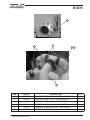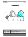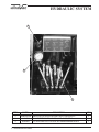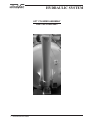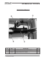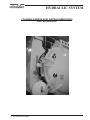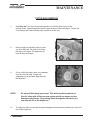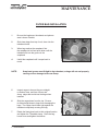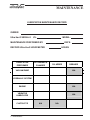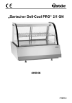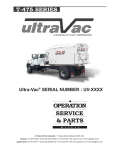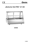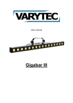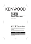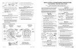
1
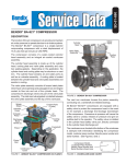
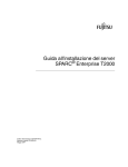
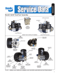
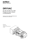
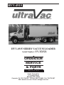
HVV-4915
A DIVISION OF Hi-Vac® CORPORATION
HVV-4915 SERIES VACUUM LOADER
Serial Number: UV-XXXX
OPERATION
SERVICE
& PARTS
M A N U A L
Hi-Vac Corporation
117 Industry Road
Marietta, Ohio 45750
Corporate: Tel: 740.374.2306 - Toll Free: 800.752.2400 - Fax: 740.374.5447
Web: www.hi-vac.com - E-mail: [email protected]
®
A DIVISION OF Hi-Vac CORPORATION
®
TABLE OF CONTENTS
INSPECTION PROCEDURES ..................................................................................................................... I.
WARRANTY / LIMITS OF LIABILITY........................................................................................................... II.
MESSAGE TO NEW OWNER..................................................................................................................... III.
WARNINGS.................................................................................................................................................IV.
SECTION 1: OPERATIONS
Prestart Procedures
Start-Up Procedures
Operational Modes
Shutdown Procedures
Dumping Procedures
Automatic Shutdowns (Machine)
Automatic Shutdowns (Engine)
SECTION 2: MACHINE SPECIFICATIONS
Powertrain
Body
Hydraulic System
Vacuum System
Pneumatic System
Electrical System
Spare Parts List
Bill of Materials
SECTION
2: MACHINE
SPECIFICATIONS
SECTION
3: MAINTENANCE
Filter Bag Removal
Filter Bag Installation
Recommended Lubricants
Daily Checks (before starting engine)
Daily Checks (engine running, clutch disengaged)
Daily Checks (engine running, clutch engaged)
Weekly Checks (before starting engine)
Weekly Checks (engine running, clutch disengaged)
Monthly Checks (before starting engine)
Maintenance Schedules & Record Forms
ULTRA-VAC® OPERATIONS, PARTS, & SERVICE MANUAL
1
®
A DIVISION OF Hi-Vac CORPORATION
®
SECTION 4: SCHEMATICS
Chassis Wiring Diagram
Electrical Schematics
Hydraulic Schematic
Pneumatic Schematic
SECTION 5: OPTIONS
As Listed
SECTION 6: ACCESSORIES
Accessories
SECTION 7: MANUFACTURERS MANUALS
OMSI PTO Parts Manual
Hibon Blower Manual
Keystone Butterfly Valve
Gresen Valve Winters Gauges
Marsh Gauges
Span Gauges Span Venting Cassapa Hydraulic Pump
Parker Filter
Global Hydraulic Vibrator
Asco Valves
Qix Filter/Regulator Puraguard Filter
Global Air Cannon
SMC Pneumatic Valves
Murphy Tachometer Hobbs Hourmeter Dwyer Instruments Nason Pressure Switch United Electric Vacuum Switch
Monitor Level Probe
Wilkerson Autodrain
ULTRA-VAC® OPERATIONS, PARTS, & SERVICE MANUAL
2
®
A DIVISION OF Hi-Vac CORPORATION
®
INSPECTION PROCEDURES
All pieces received should be inspected for damage immediately upon receipt.
1.
Damage can be most easily detected by looking for scrapes on the paint.
2.
Inspect all sheet metal and structural steel for damage such as bends, kinks or breaks.
3.
Check all wiring for abrasions, cuts, cracks, etc. If any are found, repair or replace before connecting to power source.
Check all conduit runs and fittings for defects.
4.
5.
Check vacuum pump for free rotation before starting under power for the first time after installation.
Compare the packing list attached to each piece of each shipment.
6.
7.
Verify the number of pieces and description of each piece shown on the
packing slip.
REPORT ANY DAMAGE, NO MATTER HOW SLIGHT, IMMEDIATELY TO:
Hi-Vac® Corporation
117 Industry Road
Marietta, OH 45750
Attention: Service Department
Phone: 740.374.2306
Toll Free: 800.752.2400
Fax: 740.374.5447
ULTRA-VAC® OPERATIONS, PARTS, & SERVICE MANUAL
3
®
A DIVISION OF Hi-Vac CORPORATION
®
WARRANTY
Hi-Vac® CORPORATION WARRANTS TO THE ORIGINAL PURCHASER OF THE Ultra-Vac® UNIT QUOTED HEREIN
THAT THE Ultra-Vac® UNIT SHALL BE FREE FROM DEFECTS IN MATERIAL AND WORKMANSHIP UNDER
NORMAL USE AND SERVICE. Hi-Vac® CORPORATION DOES NOT WARRANT COMMERCIAL ITEMS
MANUFACTURED BY OTHERS SUCH AS DIESEL ENGINES, TRUCK CHASSIS, TIRES OR MOTORS.
Hi-Vac® CORPORATION’S OBLIGATION UNDER THIS WARRANTY SHALL BE LIMITED TO THE REPAIR OR
EXCHANGE OF ANY PART OR PARTS WHICH MAY PROVE DEFECTIVE UNDER NORMAL USE AND SERVICE WITHIN THE SHORTER PERIOD OF ONE (1) YEAR FROM THE DATE OF DELIVERY TO THE ORIGINAL
PURCHASER AND WHICH Hi-Vac® CORPORATION’S EXAMINATION SHALL DISCLOSE TO ITS SATISFACTION TO BE DEFECTIVE. THIS WARRANTY REQUIRES PURCHASER TO OPERATE THE Ultra-Vac® UNIT
IN STRICT COMPLIANCE WITH THE PRINTED INSTRUCTIONS AND TO SERVICE THE Ultra-Vac® UNIT
ACCORDING TO THE METHODS AND SCHEDULES CONTAINED IN THE Ultra-Vac® UNIT’S MANUAL. EVIDENCE
OF PURCHASER’S SCHEDULED MAINTENANCE MUST BE REPORTED IN WRITING TO Hi-Vac® CORPORATION
ON THE FORMS SUPPLIED TO PURCHASER IN THE Ultra-Vac® MAINTENANCE MANUAL. SHOULD PURCHASER
BELIEVE A DEFECT HAS BEEN DISCOVERED, THE PURCHASER SHALL RETURN THE ALLEGED DEFECTIVE
PART TO Hi-Vac® CORPORATION FOR EXAMINATION, F.O.B THE Hi-Vac® PLANT, MARIETTA, OHIO. IN THE
EVENT PURCHASER DOES NOT SERVICE AND MAINTAIN THE Ultra-Vac® UNIT ACCORDING TO THE Ultra-Vac®
MAINTENANCE MANUAL, THE WARRANTY IS TO BE CONSIDERED NULL AND VOID AND
Hi-Vac® CORPORATION’S OBLIGATION HEREUNDER SHALL BE DEEMED FULFILLED. THIS WARRANTY IS EXPRESSLY IN LIEU OF ALL OTHER WARRANTIES EXPRESSED OR
IMPLIED, INCLUDING THE WARRANTIES OF MERCHANTABILITY AND FITNESS FOR USE
AND OTHER OBLIGATIONS OR LIABILITIES ON THE PART OF Hi-Vac® CORPORATION.
LIMITS OF LIABILITY
Hi-Vac® CORPORATION SHALL NOT BE LIABLE FOR AND PURCHASER ASSUMES RESPONSIBILITY FOR ALL
PERSONAL INJURY AND PROPERTY DAMAGE RESULTING FROM THE HANDLING, POSSESSION
OR USE OF YOUR Ultra-Vac® INDUSTRIAL VACUUM LOADER BY THE PURCHASER. THE LIABILITY OF Hi-Vac® CORPORATION ARISING OUT OF THE SUPPLYING OF YOUR Ultra-Vac ® INDUSTRIAL VACUUM LOADER, OR ITS USE WHETHER ON WARRANTIES OR CLAIM OF NEGLIGENCE
OR OTHERWISE, SHALL NOT IN ANY CASE EXCEED THE COST OF CORRECTING DEFECTS IN
YOUR Ultra-Vac® INDUSTRIAL VACUUM LOADER AS HEREIN PROVIDED. Hi-Vac® CORPORATION
SHALL NOT IN ANY EVENT BE LIABLE FOR ANY LABOR EXPENDED BY THE PURCHASER ON ANY
PART OR PARTS OR FOR ANY SPECIAL DIRECT OR INDIRECT OR CONSEQUENTIAL DAMAGES.
NO MATERIAL MAY BE RETURNED WITHOUT FIRST GETTING APPROVAL FROM Hi-Vac® CORPORATION. ANY
GOODS RETURNED WITH SUCH APPROVAL MUST BE SENT BACK WITH ALL TRANSPORTATION CHARGES
PREPAID WITHIN 30 DAYS AFTER ISSUANCE OF APPROVAL. GOODS RETURNED AND ACCEPTED IN
ACCORDANCE
WITH THE ABOVE
CONDITIONS
WILL BE
CREDITED ON THE BASIS OF THE PRICES PAID AT TIME OF SHIPMENT.
ULTRA-VAC® OPERATIONS, PARTS, & SERVICE MANUAL
4
®
A DIVISION OF Hi-Vac CORPORATION
®
MESSAGE TO NEW OWNER
Congratulations on your purchase of a new Ultra-Vac® Vacuum Loader.
This manual is supplied for your convenience to assist you in adequately
maintaining, servicing and operating your Ultra-Vac® Vacuum Loader.
Your Ultra-Vac® Vacuum Loader has been designed to give you many
years of dependable, trouble free service, which can be attained only
through conscientious care by your personnel. Therefore, cooperation,
practice and skill on the part of all personnel associated with your
Ultra-Vac® is necessary to maintain maximum productivity.
The material in this manual has been carefully and thoughtfully prepared
to provide a simple and understandable guide. It should be carefully read
and thoroughly understood by all personnel responsible for your Ultra-Vac®
before engaging in both operation and the maintenance of the system.
The very best wishes from our entire organization are extended to you with
the assurance that you will enjoy long and dependable service from this
Ultra-Vac®.
ULTRA-VAC® OPERATIONS, PARTS, & SERVICE MANUAL
5
®
A DIVISION OF Hi-Vac CORPORATION
®
SAFETY
PRECAUTIONS
ULTRA-VAC® OPERATIONS, PARTS, & SERVICE MANUAL
®
A DIVISION OF Hi-Vac CORPORATION
®
CAUTION
SOME DO’S AND DON’TS BEFORE GETTING STARTED WITH YOUR
NEW Ultra-Vac® SYSTEM.
The safety of the operator is of great importance to us at Hi-Vac® Corporation. The decals,
shields, guards and other protective features that are designed into the machine are there for your
protection. A high percentage of the accidents that occur are due to careless behavior or misuse
of machinery. We ask you to be a careful operator and to properly service your machine.
PROCEED WITH CAUTION
Before attempting to operate the machine, read carefully and understand all instructions contained in the manual.
IT IS VERY IMPORTANT THAT YOU UNDERSTAND THE FOLLOWING SAFETY WARNINGS
IN FULL. INJURY OR DEATH TO PERSONNEL, AND/OR DAMAGE TO MACHINE CAN
RESULT.
*
Unit should only be operated by thoroughly trained personnel.
*
Do not put your face or any portion of head in front of the nozzle.
*
Hearing protection must be worn by operator and those working near the vacuum loader.
*
Do not operate machinery without proper guards in place. Keep away from moving objects.
*
Do not put your hand in front of the intake nozzle while in operation.
*
Do not vacuum any flammable liquid.
*
Check that unit is properly stopped and parking brake applied so unit will not tip or roll.
*
Do not lubricate, adjust or repair the Ultra-Vac® unit unless engine is shut down.
*
Do not operate the unit with the levelprobe “ON/OFF” switch in the “OFF” position.
ULTRA-VAC® OPERATIONS, PARTS, & SERVICE MANUAL
1
®
A DIVISION OF Hi-Vac CORPORATION
®
*
NEVER raise body when parked on uneven ground.
*
NEVER raise the body if baghouse is overloaded.
*
NEVER raise body unless the tailgate is fully open.
*
NEVER operate tailgate while body is in elevated position.
*
*
NEVER move the Ultra-Vac® unless the body is in the fully down
position.
*
*
Never inspect or work under the raised body without the safety body prop in place.
*
Do not operate the Ultra-Vac® unit while wearing loose clothing, watches or rings.
Periodically check for any loose bolts or set screws.
*
Clear the area behind the Ultra-Vac® of all personnel before
opening or closing the tailgate.
NEVER inspect or work under the open tailgate without a tailgate prop in place.
NOTE:
AS WITH ANY TYPE OF HEAVY DUTY EQUIPMENT, CAUTION MUST BE EXERCISED IN ITS PROPER USE.
WARNING:
FAILURE TO COMPLY WITH ANY OF THE ABOVE SAFETY INSTRUCTIONS OR THOSE THAT FOLLOW WITHIN THIS MANUAL MAY RESULT IN DAMAGE TO EQUIPMENT AND/OR SEVERE INJURY OR DEATH!
PLEASE REMEMBER:
Safe operation begins with a safe operator. We ask you to be that type of operator.
ULTRA-VAC® OPERATIONS, PARTS, & SERVICE MANUAL
2
®
A DIVISION OF Hi-Vac® CORPORATION
OPERATIONS
ULTRA-VAC® OPERATIONS, PARTS, & SERVICE MANUAL
®
OPERATIONS A DIVISION OF Hi-Vac CORPORATION
®
PRESTART PROCEDURES
Before prestarting your Ultra-Vac® unit, be sure you have read and understood all of
the safety warnings and precautions located in the Machine Safety section.
1
2
Truck must be located on level ground and set trailer brake.
Visually inspect the unit so that there are no obstructions which may cause harm to machine or operating personnel.
3
Check oil level in Vacuum Pump and Transfer Case.
4
Check oil and coolant levels in Engine.
5
Check Hydraulic oil level and add if necessary.
6
Check all Hydraulic hoses and fittings for leaks. Repair if necessary.
7
Check that all doors are closed and locked.
8
Attach vacuum loading hose. Remove dust cap from the end of hose.
You are now ready to start your Ultra-Vac® unit.
ULTRA-VAC® OPERATIONS, PARTS, & SERVICE MANUAL
1
OPERATIONS
®
A DIVISION OF Hi-Vac® CORPORATION
OPERATIONS START-UP PROCEDURES
Before starting up your Ultra-Vac® unit, Be sure you have done all the pre-start
procedures located on the previous page.
1
Start the chassis engine. Be sure that the chassis parking brake has been applied.
2
Allow Engine to idle until air pressure is built up before engaging Vacuum Pump.
WARNING: The Transfer case air system will not function properly until air pressure is at least 60 psi.
3 Depress the clutch pedal to disengage the transmission. Switch the “Road/ Pump” switch located on the dash to the “Pump” position. Put the transmission in the gear indicated on the label located on the dash. Release the clutch.
4
At this point the rear drive shaft should be disengaged and hydraulic system is on.
5
At engine idle speed, Depress the clutch pedal and Switch the “Blower On/Off” switch to the “On” position. Release the clutch. At this time the blower will be turning. Be sure to only engage and disengage at idle speed only.
WARNING: Never engage blower above 1,000 RPM’s.
6
After Vacuum Pump is engaged, switch the “Auto/Manual “ switch to the desired mode and increase the engine speed until you are at desired speed.
WARNING: Level Probe “ON/OFF” switch must be “ON” at all times during vacuuming operations.
Once the unit is at operating speed, you may begin loading material. Periodically check
gauges to ensure the unit is running properly.
The Ultra-Vac® has built-in shut downs. If a shut down occurs, immediately stop work and
remedy the situation.
ULTRA-VAC® OPERATIONS, PARTS, & SERVICE MANUAL
2
OPERATIONS
®
OPERATIONS A DIVISION OF Hi-Vac CORPORATION
®
OPERATIONAL MODES
This unit has two operational modes. They can be selected at the side control panel.
WARNING:
If your unit is equipped with a Level Probe “ON/OFF” switch the switch must be in the “ON” position during vacuuming operations. Failure to operate the unit in this manner could result in damage to equipment or severe injury or death.
AUTOMATIC:
MANUAL:
The engine increases speed until it reaches a preset maximum
operational blower speed. A hopper full light will lower the engine speed back to an idle condition. At this point the box must be emptied before the operations can continue.
In this mode engine speed it controlled through the throttle emulator. Likewise a hopper full light will return the engine to a idle condition until the hopper has been emptied.
OFF/RESET:
This switch position will allow the throttle to be used for dumping the box.
SHUTDOWN PROCEDURES
Before stopping unit, allow the Ultra-Vac® to run for a moment to let the lines clean out.
1
At the side control panel, move the mode switch to the OFF/RESET position.
At this point the engine should return to an idle condition.
WARNING: Never disengage Blower above 1,000 RPM’s.
2
If time allows, let Vacuum Pump run at low RPM to cool down.
3
On the dash disengage the blower by depressing the clutch and moving the blower switch to the off position. Move the PTO switch to the OFF or Disengaged position. Release the clutch.
Turn the ignition key switch to “Off” position.
4
ULTRA-VAC® OPERATIONS, PARTS, & SERVICE MANUAL
3
OPERATIONS
OPERATIONS ®
A DIVISION OF Hi-Vac CORPORATION
®
DUMPING PROCEDURES
Before dumping material out of the collector body, be sure that the parking brake is on and the unit is
on level ground. Also ensure there are no personnel or obstructions near the Ultra-Vac®. This could
result in damage to machinery or injury to personnel. If equipped with manual dump door locks on the
baghouse and cyclone hopper dump doors, release the locks to allow the dump doors to open during
each dumping of the collector body.
CAUTION: Do not raise the body if the baghouse is overloaded.
WARNING: Failure to do so can result in sever injury or death, and/or damage to the
equipment.
Dumping The Body:
1
Pull the handle valve marked “Lock/Unlock” to unlock tailgate prior to raising. Be sure that there are no personnel at the back of the Ultra-Vac® unit.
2
Pull the handle valve marked “Tailgate Open/Close” to open the tailgate. Be sure that there are no personnel at the back of the Ultra-Vac® unit.
WARNING:
3
Never open the tailgate without first unlocking. This will cause damage to the equipment.
Pull the valve marked “Raise/Lower” to fully raise the collector body.
WARNING: Be sure that the Ultra-Vac® is on a level surface before raising the collector body. Possible tipping may occur.
4
Pull the valve marked “Vibrator On/Off” to run the hydraulic vibrator to loosen materials in the collector body, baghouse and cyclone hopper. Ensure the baghouse and cyclone hopper are completely empty of material after each dumping cycle.
ULTRA-VAC® OPERATIONS, PARTS, & SERVICE MANUAL
4
OPERATIONS
OPERATIONS ®
A DIVISION OF Hi-Vac CORPORATION
®
DUMPING PROCEDURES
(continued)
5
After inspecting the Blower Inlet Screen, lower the collector body, close the tailgate, and then lock the tailgate locks.
WARNING:
Never work under body or tailgate in the raised position unless the appropriate props are in place. Never move the Ultra-Vac® with the collector body in the raised position.
Inlet Screen
ULTRA-VAC® OPERATIONS, PARTS, & SERVICE MANUAL
5
OPERATIONS
OPERATIONS ®
A DIVISION OF Hi-Vac CORPORATION
®
AUTOMATIC SHUTDOWNS (MACHINE)
There are two types of automatic shutdowns on the HVV-4915; Machine shutdowns, which are shutdowns directly related to the Unit, and Engine shutdowns. You will have to correct the problem
before restarting.
MACHINE SHUTDOWNS - The following conditions will cause the engine to return to an idle condition or stop the engine.
1
2
HOPPER FULL
Caused by material filling up inside the collector body and activating the Level Probe. This is indicated by a light on the control panel. Simply dump material out of the
collector body and move the mode switch to the “Vac OFF/ Reset” position. The
Hopper Full light should go out. Return the mode switch to either the Automatic or Manual positions and you may then continue loading. Always return the Level Probe “ON/OFF” switch to the “ON” position before resuming vacuuming operations.
EMERGENCY STOP BUTTON
In the event of an emergency situation press the emergency stop button. This button will remove power from the control panel and will stop the engine. To resume loading pull out on the Emergency Stop button and follow the start up procedure.
AUTOMATIC SHUTDOWNS (ENGINE)
ENGINE SHUTDOWNS -
ULTRA-VAC® OPERATIONS, PARTS, & SERVICE MANUAL
6
OPERATIONS
See the Chassis Manual for instructions on engine warnings and fault displays.
®
A DIVISION OF Hi-Vac CORPORATION
®
MACHINE
SPECIFICATIONS
ULTRA-VAC® OPERATIONS, PARTS, & SERVICE MANUAL
POWERTRAIN ®
A DIVISION OF Hi-Vac® CORPORATION
OMSI PTO
PART NO.A249437
ULTRA-VAC® OPERATIONS, PARTS, & SERVICE MANUAL
1
MACHINE SPECIFICATIONS
BODY ®
A DIVISION OF Hi-Vac® CORPORATION
1
4
2
5 6
3
ITEM
PART #
1
U4307-0008
2
QTY
VALVE,BUTTERFLY,6”,HAND LEVER ACTUATOR
1
18-0539
SLEEVE,10”PIPE X 5”LG,7/16”WALL,EPDM
2
3
18-0536
SLEEVE,6” PIPE X 6”LG,7/16 WALL,EPDM
2
4
18-0538
SLEEVE,10”PIPE X 8” LG,7/16 WALL,EPDM
1
5
10-0204
CAMLOCK,4” MALE X 4”FNPT,TYPE A ALUM
2
6
10-0219
CAMLOCK,4,DUST CAP,ALUM
2
ULTRA-VAC® OPERATIONS, PARTS, & SERVICE MANUAL
2
DESCRIPTION
MACHINE SPECIFICATIONS
BODY ®
A DIVISION OF Hi-Vac CORPORATION
®
2 1
3 4
5 6
ITEM
1
2
3
4
5
6
PART #
U1007-4237
U3807-0065
U1007-4236
U3807-0064
U3701-0081
U3702-0032
DESCRIPTION
DOOR,CENTER,BAGHOUSE
GASKET ASSY,BAGHOUSE,CENTER,HVV4915
DOOR,BAGHOUSE
GASKET ASSY,BAGHOUSE,FRONT&REAR,HVV4915
FILTER BAG,16OZ MICROFINER,60-1/2”L
CAGE,FILTER,STL,60” LG
ULTRA-VAC® OPERATIONS, PARTS, & SERVICE MANUAL
3
MACHINE SPECIFICATIONS
QTY
1
1
2
2
68
68
BODY ®
A DIVISION OF Hi-Vac CORPORATION
®
SIGHT EYE ASSEMBLY
(2) REQUIRED
ITEM
1
2
3
4
5
PART #
A153013
A153000
A153014
A152890
A153012
ULTRA-VAC® OPERATIONS, PARTS, & SERVICE MANUAL
4
MACHINE SPECIFICATIONS
DESCRIPTION
HAND WHEEL, SIGHT EYE
FRAME, SIGHT EYE, THREADED, 1/2” x 13
PRESSURE PAD, SIGHT EYE, CAST
SIGHT GLASS
GASKET, SIGHT EYE, RUBBER
QTY
1
1
1
1
1
®
A DIVISION OF Hi-Vac CORPORATION
®
HYDRAULIC SYSTEM HYDRAULIC PUMP
PART NO.U3902-0085
ULTRA-VAC® OPERATIONS, PARTS, & SERVICE MANUAL
5
MACHINE SPECIFICATIONS
HYDRAULIC SYSTEM ®
A DIVISION OF Hi-Vac CORPORATION
®
3
2
1
ITEM
1
2
3
PART #
U3904-0158
A131786
A383925
DESCRIPTION
VALVE,HYD,4 SPOOL,DRYVAC W/PO CHKS,W/STP
GAUGE,PRESSURE,0-5K PSI, W/FLANGE,STAB
POTENTIOMETER,FOR USE W/CUMMINS&MERCEDES
ULTRA-VAC® OPERATIONS, PARTS, & SERVICE MANUAL
6
MACHINE SPECIFICATIONS
QTY
1
1
1
®
A DIVISION OF Hi-Vac CORPORATION
®
HYDRAULIC SYSTEM LIFT CYLINDER ASSEMBLY
PART NO.U3903-0053
ULTRA-VAC® OPERATIONS, PARTS, & SERVICE MANUAL
7
MACHINE SPECIFICATIONS
HYDRAULIC SYSTEM ®
A DIVISION OF Hi-Vac CORPORATION
®
REAR DOOR HYDRAULICS
4
2
3
ITEM
1
2
3
4
PART #
A110015-1
A110019
A246183
08-0020
ULTRA-VAC® OPERATIONS, PARTS, & SERVICE MANUAL
8
MACHINE SPECIFICATIONS
1
DESCRIPTION
CYLINDER,HYDRAULIC,TANK DOOR,5” X 6.75’
VALVE,CHECK/RELIEF,INTEGRATED ASSEMBLY
PIN,PIVOT,REAR DOOR CYLINDER
PIN,SPRING,1/4” DIA X 3-1/2”LG,PLN STL
QTY
1
1
2
4
®
A DIVISION OF Hi-Vac CORPORATION
®
HYDRAULIC SYSTEM CYLINDER & WEDGE ASSY (UPPER/LOWER DOOR)
PART NO.A246523-P
ULTRA-VAC® OPERATIONS, PARTS, & SERVICE MANUAL
9
MACHINE SPECIFICATIONS
®
A DIVISION OF Hi-Vac CORPORATION
®
HYDRAULIC SYSTEM 35 GALLON HYDRAULIC TANK
1
2
3
ITEM
1
2
3
4
PART #
U3907-0038
A110580
A140030
A110515
ULTRA-VAC® OPERATIONS, PARTS, & SERVICE MANUAL
10
MACHINE SPECIFICATIONS
DESCRIPTION
TANK,HYDRAULIC,35GAL.,W/BREATHER FILTER
SIGHT EYE,2” OIL LEVEL
VALVE,GATE,1-1/4” BRASS,MO
FILTER ASSY.,HYD.,1-1/4”NPT,25M ELEMENT
4
QTY
1
1
1
1
®
A DIVISION OF Hi-Vac CORPORATION
®
HYDRAULIC SYSTEM HYDRAULIC VIBRATOR
PART NO.U3917-0007
ULTRA-VAC® OPERATIONS, PARTS, & SERVICE MANUAL
11
MACHINE SPECIFICATIONS
®
A DIVISION OF Hi-Vac CORPORATION
®
HYDRAULIC SYSTEM HYDRAULIC HOSE KIT
PART #U4901-0069
ITEM
1
2
3
4
5
6
7
8
9
10
11
12
13
14
15
16
17
18
PART #
U4901-0069-01
U4901-0069-02
U4901-0069-03
U4901-0069-04
U4901-0069-05
U4901-0069-06
U4901-0069-07
U4901-0069-08
U4901-0069-09
U4901-0069-10
U4901-0069-11
U4901-0069-12
U4901-0069-13
U4901-0069-14
U4901-0069-15
U4901-0069-16
U4901-0069-17
U4901-0069-18
ULTRA-VAC® OPERATIONS, PARTS, & SERVICE MANUAL
12
MACHINE SPECIFICATIONS
DESCRIPTION
HOSE ASSY,1"-R2-19,#16FJICSX#16FJICSSR90
HOSE ASSY,3/4"-R2-26,#12FJICSX#12FJICS
HOSE ASSY,5/8"-R2-93,#10FJICSX#10FJICSSR
HOSE ASSY-5/8"-R2-138,#10FJICSX#10FJICSS
HOSE ASSY,1/2"-R2-123,#8FJICSX#8FJICSLR9
HOSE ASSY,1/2"-R2-123,#8FJICSX#8FJICSSR9
HOSE ASSY,1/2"-R2-51,#8FJICSX#8JICS
HOSE ASSY,1/2"-R2-23,#8FJICSX #8FJICS
HOSE ASSY,1/2"-R2-135,#8FJICSX#8FJICS
HOSE ASSY,1/2"-R2-122,#8FJICSX#8FJICSLR9
HOSE ASSY,1/2"-R2-117,#8FJICSX#8FJICSSR9
HOSE ASSY,1/2"-R2-111,#8FJICSX#8FJICS
HOSE ASSY,1/2"-R2-41",#8FJICSX#8FJICS
HOSE ASSY,1/2"-R2-39,#8FJICSX#8FJICS
HOSE ASSY,1/2"-R2-63,#8JICSX#8FJICS
HOSE ASSY,1/2"-R2-70,#8FJICSX#8FJICS
HOSE ASSY,3/8"-R2-11.5,#8FJICSX#8FJICS
HOSE ASSY,3/8"-R2-21,#6FJICSX#8FJICS
QTY
1
1
1
1
3
3
3
1
2
1
1
2
3
2
1
1
1
1
VACUUM SYSTEM ®
A DIVISION OF Hi-Vac CORPORATION
®
BLOWER & SILENCERS
2
1
3
ITEM
1
2
3
PART #
03-0108
U4201-0333
U4201-0334
DESCRIPTION
BLOWER,HIBON 8702,BH-CCW,HVV
SILENCER,INTAKE,HVV5015,HIBON 8702
SILENCER,EXHAUST,HVV5015,HIBON 8702
ULTRA-VAC® OPERATIONS, PARTS, & SERVICE MANUAL
13
MACHINE SPECIFICATIONS
QTY
1
1
1
VACUUM SYSTEM ®
A DIVISION OF Hi-Vac CORPORATION
®
6” AIR OPERATED VACUUM RELIEF,HVV4915
PART #UV1-9171
1
ITEM
1
PART #
16-0347
DESCRIPTION
VALVE, BUTTERFLY, 12VDC
ULTRA-VAC® OPERATIONS, PARTS, & SERVICE MANUAL
14
MACHINE SPECIFICATIONS
QTY
1
PNEUMATIC SYSTEM ®
A DIVISION OF Hi-Vac CORPORATION
®
2
1
3
ITEM
1
2
3
PART #
13-0100
A249447
A383781
DESCRIPTION
VSWITCH,VACUUM,0-30” HG
SWITCH,PRESSURE,20-120 PSI,MR,1/8MNPT
VALVE ASSY,2SPOOL,4WAY,12V,DRYVAC
ULTRA-VAC® OPERATIONS, PARTS, & SERVICE MANUAL
15
MACHINE SPECIFICATIONS
QTY
1
1
1
PNEUMATIC SYSTEM ®
A DIVISION OF Hi-Vac® CORPORATION
3
MANUAL DRAIN VALVE
ITEM
PART #
1
2
3
4
5
15-0453
15-0044
U4003-0140
U4003-0141
U3904-0027
MACHINE SPECIFICATIONS
2
DESCRIPTION
VALVE,SOLENOID,12VDC
REGULATOR,QIX INT FIL
FILTER,PURAGUARD AIR SYSTEM
VALVE,PRESSURE PROTECTION,1/2” X 3/8”NPT
VALVE,CHECK,1/2”
ULTRA-VAC® OPERATIONS, PARTS, & SERVICE MANUAL
16
4
1
5
QTY
1
1
1
1
1
PNEUMATIC SYSTEM ®
A DIVISION OF Hi-Vac CORPORATION
®
2
1
3
4
ITEM
PART #
1
2
3
4
A383844
A249433
U0101-0729
A151550
DESCRIPTION
VALVE,AIR,3WAY,1/2”,12V DC
AIR CANNON,GLOBAL #GW4-20-30,DRY VAC
VALVE,AUTODRAIN,.38NPT
PETCOCK,3/8”
ULTRA-VAC® OPERATIONS, PARTS, & SERVICE MANUAL
17
MACHINE SPECIFICATIONS
QTY
1
1
1
1
®
A DIVISION OF Hi-Vac CORPORATION
®
ELECTRICAL SYSTEM 2
1
4
3
5
ITEM
1
2
3
4
5
PART #
A383409
U4008-0002
U4008-0001
U4008-0004
A120040
ULTRA-VAC® OPERATIONS, PARTS, & SERVICE MANUAL
18
MACHINE SPECIFICATIONS
DESCRIPTION
TACHOMETER,MURPHY,12V,7-21PUL/REV
GAUGE,DIFFERENTIAL PRESSURE,0-50” WC
GAUGE,VACUUM,0-30”HG,PANEL MOUNT
GAUGE,AIR PRESSURE,0-200 PSI
HOURMETER,HOBBS,10-80VDC,3-HOLE ROUND
E-STOP
QTY
1
1
1
1
1
ELECTRICAL SYSTEM ®
A DIVISION OF Hi-Vac® CORPORATION
LEVEL PROBE,MONITOR,12VDC,KA SRS
PART NO.27-0005
ULTRA-VAC® OPERATIONS, PARTS, & SERVICE MANUAL
19
MACHINE SPECIFICATIONS
®
A DIVISION OF Hi-Vac CORPORATION
®
ITEM
1
2
3
4
5
6
7
8
9
10
11
12
13
14
PART #
U3807-0064
U3807-0065
U3803-0031
U3807-0023
A191100-NH
U3701-0081
U3702-0032
U3803-0032
03-0108
GASKET
U3809-0093
A110515
20-0069
15-0044-F
U4003-0140-MK
ULTRA-VAC® OPERATIONS, PARTS, & SERVICE MANUAL
20
MACHINE SPECIFICATIONS
SPARE PARTS LIST
DESCRIPTION
GASKET ASSY,BAGHOUSE,FRONT&REAR
GASKET ASSY,BAGHOUSE,CENTER
GASKET,FLANGE,150#,12”,HIGH TEMP SIL
GASKET,10” STANDPIPE, FOR 9 CU. YD. BOX
GASKET,REAR DOOR,18’-6”,W/O HOLE
FILTER BAG,16oz MICROFIBER,60 1/2 LG.
CAGE,FILTER,STL,60” LG
GASKET,BLOWER INLET,HIBON 8702,HI TE SIL
GASKET, BLOWER TO MANIFOLD
QTY
2
1
2
1
1
68
68
1
1
GASKET,DUMP DOOR
FILTER ASSY.,HYD.,1-1/4”NPT,25M ELEMENT
FILTER TUBE,PRESSURE DIFFERENTIAL
FILTER,REPLACEMENT FOR QIX REGULATOR
MAINTENANCE KIT,PURAGUARD FILTER
4
1
1
1
REF
®
A DIVISION OF Hi-Vac® CORPORATION
MAINTENANCE
ULTRA-VAC® OPERATIONS, PARTS, & SERVICE MANUAL
®
MAINTENANCE
A DIVISION OF Hi-Vac CORPORATION
®
FILTER BAG REMOVAL
1
With Ultra-Vac® unit shut off and parking brake on, carefully climb on top of the
collector body. Open all baghouse doors to gain access to filters and cages. Loosen the t-bolt clamps and rotate the blast pipes up and out of the way.
2
Remove cages by carefully pulling up and out of the filter bag. Be sure not to catch the bag on the cages. The baghouse will have 68 bags and cages.
3
On top of the filter bags, there is a snapband sewn into the filter bag. Simply fold
snapbands in half and push bags through the tubesheet.
NOTE:
4
Do not pull filter bags up and out. This will bring dirty material up into the clean-side of the vacuum system which can cause serious damage to the blower. By pushing them through the tubesheet you
can keep all dirt in the baghouse
The bags can then be removed through the baghouse access doors located at the front and rear of the baghouse.
ULTRA-VAC® OPERATIONS, PARTS, & SERVICE MANUAL
1
MAINTENANCE
®
MAINTENANCE
A DIVISION OF Hi-Vac CORPORATION
®
FILTER BAG INSTALLATION
1
Be sure the baghouse, tubesheets and plenum area is clean of debris.
2
Slide clean bags from top of unit, down into the tubesheet holes.
3
When bag reaches the snapband, fold
the snapband in half and push down until the tubesheet fits into the groove in the
snapband.
4
Unfold the snapband until it snaps back to round.
NOTE:
Snap band groove must fit tight in the tubesheet, or bags will not seal properly causing serious damage to Vacuum Pump.
5
Inspect cages to be sure they are straight,
no broken wires, and free of burrs and sharp edges that could tear the bags when installed.
6
Slide the cages down from the top. Be sure
to slide straight down to keep from damaging the bags. The cages should slide tight against the
tubesheet completely covering the bag.
7
Rotate the blast pipes back to their original location
and tighten the T-handled clamp. Close the bag house doors and tighten the latches.
ULTRA-VAC® OPERATIONS, PARTS, & SERVICE MANUAL
2
MAINTENANCE
®
MAINTENANCE
A DIVISION OF Hi-Vac CORPORATION
®
RECOMMENDED LUBRICANTS
1
Positive Displacement Vacuum Pump (Blowers)
Follow the recommendations of the blower manufacturers manual located in the Manufacturer’s Manuals section.
2
Hydraulic System
a) All hydraulic systems furnished for use on Ultra-Vac® units will be supplied with AW-46 oil.
b)
3
4
5
Tailgate locks and Pivot pins shall use a High Grade, Lithium base, No. 2 Bearing grease.
Engine
Follow the recommendations of the motor manufacturers manual located in the Manufacturer’s Manuals section.
PTO
Dexron III transmission fluid.
Lubricator (If applicable)
ISO VG32 or equivalent
SCHEDULED LUBRICATION CHART
GEAR END OIL
BLOWER
HIBON
8702
DRIVE END OIL
CHECK
DAILY
CHECK
DAILY
PTO
MAIN HOUSING
CHECK
DAILY
HYDRAULIC
SYSTEM
OIL RESERVOIR
CHECK
DAILY
TANK
REAR DOOR CYLINDER
REAR DOOR PINS
REAR DOOR HINGE PINS
CHECK
TANK TIPPING PINS
MONTHLY
CYLINDER PINS
ULTRA-VAC® OPERATIONS, PARTS, & SERVICE MANUAL
3
MAINTENANCE
CHANGE
AFTER FIRST
200 HRS:
CHANGE
EVERY 1000 HRS
or
EVERY 6 MO.
HEREAFTER
6.34 PINTS
EACH IN DRIVE
END
&
DRIVEN END
CHECK
BLOWER
MANUAL
CHANGE
EVERY
300 HRS
12.25 QUARTS
DEXRON III
ANNUALLY
35 GALLONS
AW-46
OIL
CHANGE
EVERY
100 HRS
1-2
SHOTS
LITHIUM #2
SHORT
FIBER
®
MAINTENANCE
A DIVISION OF Hi-Vac CORPORATION
®
LUBRICATION MAINTENANCE RECORD
OWNER
Ultra-Vac® SERIAL #
UV-
MODEL:
MAINTENANCE PERFORMED BY
RECORD Ultra-Vac® HOUR METER
LUBRICATION
PERFORMED
OIL DRAINED &
CHANGED
DATE:
HOURS
OIL ADDED
VACUUM PUMP
GREASED
N/A
HYDRAULIC SYSTEM
ENGINE
N/A
VIBRATOR
LUBRICATOR
N/A
CLUTCH PTO
ULTRA-VAC® OPERATIONS, PARTS, & SERVICE MANUAL
4
MAINTENANCE
N/A
N/A
®
MAINTENANCE
A DIVISION OF Hi-Vac® CORPORATION
DAILY CHECKS (before starting engine)
Perform the daily maintenance checks listed below and record on record sheet 1.
1
Vacuum Pump Oil Level Checking the vacuum pump oil level is critical and should be
done frequently. Some vacuum pumps have oil level sight
gauges, and others have oil level plugs. Refer to the vacuum pump’s maintenance manual located in the manufacturer’s bulletins section, to determine proper oil level requirements. If oil
is needed, see “Recommended Lubricants” in the “Maintenance”
section.
NOTE: Unit must be on level surface to get an accurate oil level reading.
2
Engine Oil & Coolant Levels
a)
Check engine oil when engine is cool to get a more accurate reading. Record on Daily Maintenance Schedule Record.
b)
When engine is cool, remove Radiator Cap and check Coolant level. Record on Daily Maintenance Schedule Record.
CAUTION:
Never Remove Radiator Cap when engine is warm.
3
Hydraulic Oil
Check oil level on site glass on the side of the Hydraulic tank. Record on Daily Maintenance Schedule Record.
4
PTO
Check the PTO fluid level in the sightglass located on the drivers side frame. Fluid level should be at the center of the sightglass. Add/remove fluid as appropriate.
ULTRA-VAC® OPERATIONS, PARTS, & SERVICE MANUAL
5
MAINTENANCE
®
A DIVISION OF Hi-Vac CORPORATION
®
MAINTENANCE
DAILY CHECKS (engine running, clutch disengaged)
Perform the daily maintenance checks listed below and record on record sheet 1.
5
Compressed Air Pressure Switch
When the engine is started, watch the “Air Pressue Gauge” mounted on the rear of the battery box and the “Low Air Pressure” light. The light will stay lit until the gauge reaches 60 PSI. Record the air pressure at which the “Low Pressure” light goes out, on the Daily Maintenance Schedule Record.
6
Air Cannon
When the air cannon is turned on, listen for the air cannon to fire inside the baghouse doors. Watch the “Air Pressure Gauge” for a drop of about 30 PSI. This should happen approximately every 15 to 30 seconds. Watch the air pressure gauge pressure rise to approximately 100 psi and the air cannon should fire. Record on the Daily Maintenance Schedule Record.
7
Compressed Air & Hydraulic Lines
When the engine is started, inspect all air and hydraulic lines, fittings, and connections for leaks. Look on the ground under unit for drops or pools of oil and record on the Daily
Maintenance Schedule Record.
ULTRA-VAC® OPERATIONS, PARTS, & SERVICE MANUAL
6
MAINTENANCE
®
A DIVISION OF Hi-Vac CORPORATION
®
MAINTENANCE
DAILY CHECKS (engine running, clutch engaged)
Perform the daily maintenance checks listed below and record on record sheet 1.
8
Filter Bag Pressure Differential
A
With the inlet to your machine open, Check differential gauge. Reading should be between 1” and 7” of water (H2O). Record
the reading on the pressure differential gauge in inches H2O
(water).
1.
If higher than 10 inches of water, a visual inspection
should be made for excessive buildup of material on
the filter bag surfaces or bridging of material between
bags. This can be done through the side access door.
9
Differential
No Load Vacuum
A
With the inlet completely open and no hoses connected,check vacuum gauge reading. This “no load” reading is an important indicator of the condition of the unit. The “no load” vacuum should be about 1 inch of mercury (Hg). Record vacuum reading in (Hg).
1.
If “no load” vacuum reading is zero (0),
a.
Inspect vacuum gauge plumbing for hose rupture, loose fittings, or plugged lines.
b.
Check that the box is properly seated on the
standpipe and that there are no leaks.
Vacuum
2.
If “no load” vacuum reading is higher,
a.
Check for obstruction in the cyclones and pipings by opening the top lids on each cyclone.
10
Dust Discharge
A
Inspect the silencer for visible dust in the air stream.
NOTE:
Shut the unit off immediately if dust is present. Any dust discharge should be corrected immediately
to protect the vacuum pump.
B
If dust is present, disengage the vacuum pump and shut down the engine. Check filter bags for rupture or leaks by opening
the top access doors and looking for any signs of dust on
top of the filter bags or under the inside of the top access door.
ULTRA-VAC® OPERATIONS, PARTS, & SERVICE MANUAL
7
MAINTENANCE
Discharge
®
MAINTENANCE
A DIVISION OF Hi-Vac CORPORATION
®
WEEKLY CHECKS (before starting engine)
Perform the weekly maintenance checks listed below and record on record sheet 2.
1
Subframe Mounts
Check bolts holding the vacuum unit to the trailer chassis.
Record on Weekly Maintenance Schedule Record.
2
Electric Cable
Visually inspect all electrical conduit, cables, and connections for signs of abrasions or breaks.
WEEKLY CHECKS (engine running, clutch disengaged)
Perform the weekly maintenance checks listed below and record on record sheet 2.
3
Level Probe
Check level probe for operation by holding the paddle. Control panel must be on with
the blower OFF. The “Hopper Full” light will turn “on” on control panel. If adjustment is necessary, refer to the level probe manual located in this operations manual. Record on the Weekly Maintenance Schedule Record.
4
Compressed Air Lines and Vacuum Leaks
Inspect all compressed air lines, fittings, and connections for possible leaks. Check the openings for possible damage to gaskets. With the machine running, listen for audible leaks around doors, hose connections, flanges, etc., and repair as required. Record on Weekly Maintenance Schedule Record.
ULTRA-VAC® OPERATIONS, PARTS, & SERVICE MANUAL
8
MAINTENANCE
®
MAINTENANCE
A DIVISION OF Hi-Vac CORPORATION
®
MONTHLY CHECKS ( before starting engine )
Perform the monthly maintenance checks listed below and record on record sheet 3.
1
Vacuum Pump Lobe Wear
Check the vacuum pump standpipe screen for visible dust by raising the collector body. If dust is present remove the vacuum pump standpipe and remove the bolts around the standpipe, located on top of blower. Look for visible signs of wear on the tips of the vacuum pump lobes.
WARNING:
2
Centrifugal Ring
Open tailgate and inspect the wear plate of the centrifugal ring on ceiling of box inside your Ultra-Vac® Unit. Repair or replace before it is worn through.
Be sure to put safety prop in place before removing the standpipe.
ULTRA-VAC® OPERATIONS, PARTS, & SERVICE MANUAL
9
MAINTENANCE
®
MAINTENANCE
A DIVISION OF Hi-Vac CORPORATION
®
DAILY MAINTENANCE SCHEDULE
BEFORE STARTING ENGINE
NO.
ACTION
PROCEDURE
1
CHECK OIL IN THE VACUUM PUMP AND
RECORD ON MAINTENANCE FORM #1
INSPECT SIGHT TUBES (4) ON VACUUM
PUMP OIL SHOULD BE VISIBLE IN THE
CENTER OF EACH TUBE
2
CHECK OIL IN THE ENGINE AND
RECORD ON MAINTENANCE FORM #1
PULL THE ENGINE DIP STICK. THE OIL
SHOULD BE UP TO MARK ON STICK.
3
CHECK OIL IN THE HYDRAULIC TANK
AND RECORD ON MAINTENANCE
FORM #1
INSPECT THE SIGHT GLASS ON THE SIDE
OF THE HYDRAULIC TANK.
AFTER STARTING ENGINE BEFORE ENGAGING BLOWER
NO.
ACTION
PROCEDURE
4
CHECK COMPRESSED AIR PRESSURE
AND RECORD THE MAXIMUM
PRESSURE ON MAINTENANCE FORM
#1
5
CHECK THE AIR CANNON FUNCTION
AND RECORD ON MAINTENANCE
FORM #1
6
INSPECT COMPRESSED AIR AND
HYDRAULIC HOSES AND THE FITTINGS
FOR WEAR AND LEAKS. RECORD ON
MAINTENANCE FORM #1
IMMEDIATELY AFTER STARTING THE
ENGINE WATCH THE AIR PRESSURE
GAUGE AND NOTE THE MAXIMUM AIR
PRESSURE
LISTEN FOR THE AIR CANNON TO EXHAUS
AIR AND FOR THE AIR PRESSURE GAUGE
TO DROP APPROXIMATELY 30 PSI. THIS
SHOULD HAPPEN APPROXIMATELY EVERY
SECONDS
LOOK AT ALL OF THE HOSES AND
FITTINGS ON THE MACHINE AND ALSO
LOOK ON THE GROUND UNDER THE
MACHINE FOR DROPS OR POOLS OF OIL.
ALSO LISTEN FOR AIR LEAKING.
AFTER STARTING ENGINE AFTER ENGAGING BLOWER AND WITH HOSE INLET UNCAPPED
AT THE INLET
NO.
ACTION
PROCEDURE
7
CHECK AND RECORD THE FILTER BAG
DIFFERENTIAL PRESSURE ON
MAINTENANCE FORM #1
SET THE ENGINE SPEED TO 1900 RPM AND
LOOK AT THE FILTER BAG DIFFERENTIAL
GAUGE ON THE CONTROL PANEL
8
CHECK AND RECORD THE NO LOAD
VACUUM ON MAINTENANCE FORM #1
SET THE ENGINE SPEED TO 1900 RPM AND
LOOK AT THE VACUUM GAUGE ON THE
CONTROL PANEL
9
INSPECT THE SILENCER DISCHARGE
FOR VISIBLE DUST. RECORD ON
MAINTENANCE FORM #1
10
CHECK THE VACUUM BREAKER VALVE
SETTING AND RECORD ON
MAINTENANCE FORM #1
ULTRA-VAC® OPERATIONS, PARTS, & SERVICE MANUAL
10
MAINTENANCE
SET THE ENGINE SPEED TO 1900 RPM AND
LOOK AT THE DISCHARGE OF THE
SILENCER IF THERE IS VISIBLE DUST,
STOP THE MACHINE AND FIX THE
PROBLEM
SET THE ENGINE SPEED TO 1900 RPM AND
COMPLETELY COVER THE INLET TO THE
MACHINE, THE VACUUM GAUGE SHOULD
INCREASE STEADILY AND THE VACUUM
BREAKER OPEN AT 27"HG AND CLOSE AT
APPROXIMATELY 25"HG
®
MAINTENANCE
A DIVISION OF Hi-Vac CORPORATION
®
WEEKLY MAINTENANCE SCHEDULE
(OR EVERY 40 HOURS OF OPERATION)
BEFORE STARTING ENGINE
NO.
1
2
ACTION
PROCEDURE
CHECK U-BOLTS HOLDING THE
VACUUM UNIT TO THE TRUCK
CHASSIS AND RECORD ON
MAINTNANCE FORM #2
CHECK OIL IN THE HYDRAULIC TANK
AND RECORD ON MAINTENANCE
FORM #1
USE A WRENCH AND TIGHTEN EACH OF
THE NUTS ON THE U-BOLTS HOLDING THE
ULTARVAC TO THE TRUCK CHASSIS
INSPECT THE SIGHT GLASS ON THE SIDE
OF THE HYDRAULIC TANK.
AFTER STARTING ENGINE BEFORE ENGAGING BLOWER
NO.
3
4
ACTION
PROCEDURE
CHECK HIGH LEVEL PROBE AND
RECORD ON MAINTENANCE FORM #2
OPEN THE REAR TAILGATE AND ENTER
THE COLLECTOR BODY AND STOP THE
LEVEL PROBE PADDLE. THE HOPPER FULL
LIGHT SHOULD TURN ON
CHECK THE COMPRESSED AIR
SYSTEM FOR LEAKS AND RECORD ON
MAINTENCE FORM #2
ALLOW THE AIR PRESSURE TO INCREASE
TO ABOVE 100PSI TURN OFF THE ENGINE
AND WATCH THE AIR PRESSURE GAUGE
THE GAUGE SHOULD REMAIN AT THE
SAME PRESSURE FOR MORE THAN 5
MINUTES
ULTRA-VAC® OPERATIONS, PARTS, & SERVICE MANUAL
11
MAINTENANCE
®
MAINTENANCE
A DIVISION OF Hi-Vac CORPORATION
®
MONTHLY MAINTENANCE SCHEDULE
BEFORE STARTING ENGINE
NO.
ACTION
PROCEDURE
1
CHECK VACUUM PUMP FOR LOBE
WEAR
AND RECORD ON MAINTENANCE
FORM #3
CHECK VACUUM PUMP BY LOOKING FOR
DUST AROUND THE STANDPIPE SEAL IF
DUST IS PRESENT REMOVE THE
STANDPIPE AND INSPECT THE BLOWER
LOBES.
2
CHECK CENTRIFUGAL RING WEAR
PLATE
FOR WEAR AND RECORD ON
MAINTENANCE FORM #3
VISUALLY INSPECT THE CENTRIFUGAL
RING
WEAR PLATE FOR SIGNS OF EXCESSIVE
WEAR
REPAIR OR REPLACE BEFORE WORN
THROUGH
ULTRA-VAC® OPERATIONS, PARTS, & SERVICE MANUAL
12
MAINTENANCE
®
MAINTENANCE
A DIVISION OF Hi-Vac® CORPORATION
MAINTENANCE RECORD FORM 1 “DAILY”
OWNER
DAILY MAINTENANCE RECORD FORM #1
Ultra-Vac® SERIAL #
UV-
MODEL:
OWNER____________________________________________________________________
MAINTENANCE
PERFORMED BY
DATE:
ULTRAVAC SERIAL NO.__________________ MODEL NO.__________________________
MAINTENANCE PERFORMED BY_______________________________________________
RECORD
Ultra-Vac® HOUR METER
HOURS
NO. OF OPERATING HOURS ON HOURMETER___________________________________
BEFORE STARTING ENGINE
NO.
ACTION
1
CHECK OIL IN THE VACUUM PUMP
2
CHECK OIL IN THE ENGINE
3
CHECK OIL IN THE HYDRAULIC TANK
GAUGE
READING
CHECKED
OK
NEEDS
REPAIR
REPAIRS
MADE
NEEDS
REPAIR
REPAIRS
MADE
AFTER STARTING ENGINE BEFORE ENGAGING BLOWER
NO.
ACTION
4
CHECK COMPRESSED AIR PRESSURE
5
CHECK THE AIR CANNON FUNCTION
6
INSPECT COMPRESSED AIR AND
HYDRAULIC HOSES AND THE FITTINGS
FOR WEAR AND LEAKS
GAUGE
READING
CHECKED
OK
AFTER STARTING ENGINE AFTER ENGAGING BLOWER
AND WITH HOSE INLET UNCAPPED AT THE INLET
NO.
ACTION
7
CHECK AND RECORD THE FILTER BAG
DIFFERENTIAL PRESSURE
8
CHECK AND RECORD THE NO LOAD
VACUUM
9
INSPECT THE SILENCER DISCHARGE FOR
VISIBLE DUST
10
CHECK THE VACUUM BREAKER VALVE
SETTING
ULTRA-VAC® OPERATIONS, PARTS, & SERVICE MANUAL
13
MAINTENANCE
GAUGE
READING
CHECKED
OK
NEEDS
REPAIR
REPAIRS
MADE
MAINTENANCE
®
A DIVISION OF Hi-Vac CORPORATION
®
MAINTENANCE RECORD FORM 2 “WEEKLY”
OWNER
Ultra-Vac® SERIAL
# UV-
WEEkLY
MAINTENANCE RECORD FORMMODEL:
#2
MAINTENANCE PERFORMED BY
DATE:
OWNER______________________________________________________________________
ULTRAVACUltra-Vac®
SERIAL NO.__________________
MODEL NO.__________________________
RECORD
HOUR METER
HOURS
MAINTENANCE PERFORMED BY_______________________________________________
NO. OF OPERATING HOURS ON HOURMETER____________________________________
BEFORE STARTING ENGINE
NO.
ACTION
1
CHECK U-BOLTS HOLDING THE ULTRAVAC
UNIT TO THE TRUCK CHASSIS
2
CHECK ALL ELECTRICAL CONDUIT,CABLES
AND CONNECTIONS FOR SIGNS OF
BREAKS OR ABRASIONS
GAUGE
READING
CHECKED
OK
NEEDS
REPAIR
REPAIRS
MADE
NEEDS
REPAIR
REPAIRS
MADE
AFTER STARTING ENGINE BEFORE ENGAGING BLOWER
NO.
ACTION
3
CHECK HIGH LEVEL PROBE
4
CHECK THE COMPRESSED AIR SYSTEM
FOR LEAKS
ULTRA-VAC® OPERATIONS, PARTS, & SERVICE MANUAL
15
MAINTENANCE
GAUGE
READING
CHECKED
OK
MAINTENANCE
®
A DIVISION OF Hi-Vac CORPORATION
®
MAINTENANCE RECORD FORM 3 “MONTHLY”
OWNER
Ultra-Vac® SERIAL #
UV-
MODEL:
MAINTENANCE PERFORMED
BY
DATE:
MONTHLY MAINTENANCE
RECORD FORM #3
RECORD Ultra-Vac® HOUR METER
HOURS
OWNER______________________________________________________________________
ULTRAVAC SERIAL NO.__________________ MODEL NO.__________________________
MAINTENANCE PERFORMED BY_______________________________________________
NO. OF OPERATING HOURS ON HOURMETER____________________________________
BEFORE STARTING ENGINE
NO.
ACTION
1
CHECK VACUUM PUMP FOR LOBE WEAR
2
CHECK CENTRIFUGAL RING WEAR PLATE
FOR WEAR
ULTRA-VAC® OPERATIONS, PARTS, & SERVICE MANUAL
16
MAINTENANCE
GAUGE
READING
CHECKED
OK
NEEDS
REPAIR
REPAIRS
MADE
®
A DIVISION OF Hi-Vac CORPORATION
®
SCHEMATICS
ULTRA-VAC® OPERATIONS, PARTS, & SERVICE MANUAL
®
A DIVISION OF Hi-Vac CORPORATION
®
OPTIONS
ULTRA-VAC® OPERATIONS, PARTS, & SERVICE MANUAL
NONE LISTED
®
A DIVISION OF Hi-Vac CORPORATION
®
ACCESSORIES
ULTRA-VAC® OPERATIONS, PARTS, & SERVICE MANUAL
®
A DIVISION OF Hi-Vac CORPORATION
®
MANUFACTURER’S
MANUALS
ULTRA-VAC® OPERATIONS, PARTS, & SERVICE MANUAL