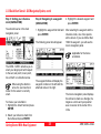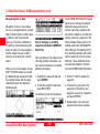
1
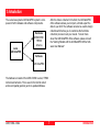
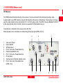
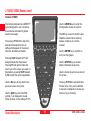
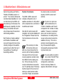
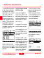
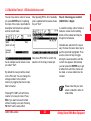
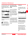
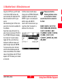
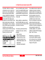
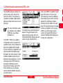
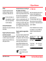
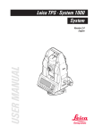
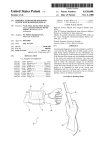
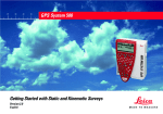
20
30
40
50
LEICA GS50 / GS50+
GIS
LEICA GS50
User Manual / Getting Started with the GS50 / GS50+
Version 4.0
English
GS50 / GS50 + Sensor
Congratulations on your purchase of a new Leica Geosystems GS50 / GS50+.
This manual contains important safety directions as well as instructions for setting up the product
and operating it. Read carefully through the User Manual before you switch on the instrument.
Preface
2
GS50 / GS50+-4.0.0en
Product Identification
The model and serial number of the GPS Sensor (GS) and Terminal (TR) are indicated on the type plate. The model
designation of the External Antenna (AT/RTB/RTS) is indicated on the housing.
Please enter them here, and always refer to this information when you need to contact your agency or service
workshop.
GPS Sensor:
Type:
Serial No.:
GPS Terminal :
Type:
Serial No.:
External Antenna :
Type:
GS50 / GS50+-4.0.0en
3
Preface
Symbols Used In This Manual
Symbols used in this manual have the following meanings:
DANGER:
Indicates an imminently hazardous situation which, if not avoided,
will result in death or serious injury.
WARNING:
Indicates a potentially hazardous situation or an unintended use
which, if not avoided, could result in death or serious injury.
CAUTION:
Indicates a potentially hazardous situation or an unintended use
which, if not avoided, may result in minor or moderate injury and /
or appreciable material, financial and environmental damage.
Important paragraphs which must be adhered to in practice as they
enable the product to be used in a technically correct and efficient
manner.
Preface
4
GS50 / GS50+-4.0.0en
Overview
GS50 / GS50+-4.0.0en
Introduction
7
System Description
8
Getting Started With New Equipment
12
Care and Transport
48
Technical Specifications
49
5
Overview
Preface
Contents
1. Introduction ............................................... 7
3.5 Offset Interface Options ........................................ 44
3.6 GIS Application .................................................... 44
3.7 Special Features ..................................................45
3.7.1 Max Trak .................................................... 45
3.7.2 Auto Stop and Threshold Settings ................ 46
3.8 Processing Data In The GIS DataPRO Software .... 47
2. System Description ................................... 8
2.1 GS50 / GS50+ Sensor .......................................... 8
2.2 GIS DataPRO Post-processing Software ............. 11
3. Getting Started With New Equipment .... 12
4. Care and Transport ................................. 48
3.1 GIS DataPRO Post Processing Software ............ 12
3.2 Receiver Hardware ............................................. 12
3.2.1 Charging batteries ..................................... 12
3.2.2 Setting up the GS50 / GS50+ for field data
collection ............................................................ 13
3.3 Using the GS50 / GS50+ Sensor ......................... 15
3.3.1 Before you begin: ....................................... 15
3.3.2 QuickStart Tutorial - GIS Data Collection .... 19
3.3.3 QuickStart Tutorial- GIS Navigation/Update 36
3.4 Real Time Differential Options ............................. 41
3.4.1 Coastguard Beacon Differential Service ........41
3.4.2 Satellite based Landstar System (RTS) ........42
Preface
Contents
5. Technical Specifications ......................... 49
5.1 GS50 / GS50+ Tracking Characteristics ................ 49
5.2 GPS Antennas .....................................................50
5.3 Equipment Weights .............................................. 50
5.4 Power ..................................................................50
5.5 Environmental Specifications ................................50
5.6 Separation Distances ........................................... 51
5.7 Baseline Precision ...............................................51
6
GS50 / GS50+-4.0.0en
1. Introduction
The Leica Geosystems GIS DataPRO system is composed of both hardware and software components.
Leica
GIS DataPRO
After the data is collected in the field, the GIS DataPRO
office software allows you to import, edit and export the
data to your GIS. The software can also be used to design
codelists which allow you to customize the field data
collection process to suit your needs. To learn more
about the GIS DataPRO office software, please consult
the "Getting Started with the GIS DataPRO Office Software User Manual".
Hardware
GS50/GS50+
TR500
Antenna
Software
GIS DataPRO
The hardware consists of the GS50 /GS50+ sensor, TR500
terminal and antenna. This is used in the field to collect
and record spatial (position) and non-spatial attributes.
GS50 / GS50+-4.0.0en
7
Introduction
Preface
2. System Description
2.1 GS50 / GS50+ Sensor
The GS50 /GS50+ sensor consists
of both ahandheld terminal (TR500),
and the GPS receiver itself. The
GPS receiver receives the GPS
signal from the NAVSTAR satellites
and calculates a range to the satellites that are visible.
The GS50 is a 12-channel L1 code
and phase GPS receiver. Phase
measurements are used internally to
smooth pseudorange measurements
for higher code positioning.
The GS50+ is a 12-channel L1, 12channel L2 code and phase GPS
receiver. The standard GS50+
records L1/L2 code and phase
measurements for post processing
and RTK purposes.
With a radio modem the receiver can
be used for RTK measurements.
Coordinates can be calculated with a
precision of 1cm.
There are several Antennas available:
GS50:
• AT501 tracks L1 only
• RTB/RTS Combined Antennas
track L1 and RTCM Differential
signals.
GS50+:
• AT502 Dual frequency antenna
• AT 503 Dual Frequency Coke Ring
Antenna
• AT504 JPL Design Dual Frequency
Choke Ring Antenna
Please see section 5 for technical
specifications.
Data can be stored for post processing in Ski-Pro or GISDataPRO.
Baselines can be calculated with a
precision of 5-10mm +/-2 ppm.
System Description
8
GS50 / GS50+-4.0.0en
2.1 GS50 / GS50+ Sensor, contd.
GPS Receiver
The TR500 terminal fits either directly on the receiver or can be connected to the terminal port using a cable.
A radio modem or an RTB module can also be fitted directly to the receiver. Alternatively, if the housing is not being
used, the radio modem can be connected to Port 1 or Port 2 using a cable. The GS50+ has an additional Port (Port 3
at the upper left side of the front plate ) that can be used also for Power/data in/out put.
The antenna is connected to the receiver via the ANT Port.
External power can be connected via a cable through the power port (PWR) or Port 2.
1.
2.
3.
4.
5.
6.
7.
8.
9.
7
8
9
5 pin Lemo. Power
Power ON/OFF
GPS Antenna in.
Port 2. 5 pin Lemo. Power/data in/out.
Pressure equalization vent.
Port 1. 8 pin Lemo. Power/data in/out.
PC Card door.
Terminal in/out or Remote Interface in/out.
Port 3. 8 pin Lemo Power/data in/out
(GS50+ only)
1
GS50 / GS50+-4.0.0en
9
2
3
4
5
6
System Description
2.1 GS50 / GS50+ Sensor, contd.
Terminal (TR500)
The terminal keyboard is a QWERTY
layout designed for use in temperature extremes and also for gloved
hands if necessary.
The six keys F1-F6 at the top of the
keyboard correspond to the six
softkeys that appear on the screen
when the terminal is activated.
Use the CONFIG key to enter the
Configuration menus at any time.
F1
HELP
F2
Use the Esc key to step back to the
previous screen at any time.
System Description
F5
F6
CE
END
P
A
R
E
S
T
F
D
X
Z
C
CONFIG
7
9
5
1
N
B
F8
±
L
F7
F9
10
L
K
CAPS
Use the ENTER key to confirm an
entry into the system.
Use the STATUS key to access
status information at any time.
Use the Cursor keys to move around
the screen.
STATUS
3
.
M
O
ENTER
6
2
0
J
SPACE
8
4
H
G
I
U
Y
V
ALT
Use the Shift key when the Shift
symbol (⇑) is displayed to reveal
further choices on the softkeys F1-F6.
F4
SHIFT
Q
W
Pressing Shift followed by F1 will
always activate the Help screen.
Pressing F6 will quit the Help and
return you to the screen you were on.
Alternatively, pressing Shift followed
by F6 will quit the current application.
F3
ESC
The CE key is used to clear the last
character entered when entering
names, numbers, etc. into the
receiver.
ON/OFF
F10
The keys F7-F10 are user definable
function keys. They can be defined
to execute commands or access any
screen of your choosing.
GS50 / GS50+-4.0.0en
2.2 GIS DataPRO Post-processing Software
GIS DataPRO is used for data
collection preparation and data post
processing.
Please refer to the "Getting Started
with the GIS DataPRO Office Software" User Manual for more details.
GS50 / GS50+-4.0.0en
11
System Description
3. Getting Started With New Equipment
3.1 GIS DataPRO Post
Processing Software
3.2 Receiver Hardware
To install the GIS DataPRO software:
Charge the batteries with the Leica
Geosystems battery charger provided. GEB121, GEB70 or GEB71
batteries may be used to power the
GPS equipment.
Use only the Leica
Geosystems batteries,
chargers and accessories, or accessories recommended by Leica
Geosystems.
The GEB121 batteries may be
charged using GKL111 or GKL122
chargers.
The GEB70 and GEB71 batteries
may be charged using GKL122 (with
charging cables), GKL23 or GKL22
chargers.
Refer to the appropriate manual
when using the chargers.
1.
2.
3.
Insert the CD-ROM into the CD
drive of your PC.
Execute the "Setup" command.
Follow the instructions that
appear on the screen.
Both a hardware and software user
manual can be found on the CD in
PDF format.
The software itself contains a comprehensive online Help System.
3.2.1 Charging batteries
The battery chargers are
intended for indoor use only.
Use a battery charger in a dry room
only, never outdoors. Charge batteries only at an ambient temperature
between 10°C and 30°C ( 50°F to
86°F ). We recommend a temperature of 0°C to +20°C (32°F to 68°F)
for storing the batteries.
Getting Started With New Equipment
12
To attain full battery capacity
for new GEB121 batteries, it
is essential to repeat between three
and five complete charge/discharge
cycles.
GS50 / GS50+-4.0.0en
3.2.2 Setting up the GS50 / GS50+ for field data collection
The following will outline the steps
necessary to set up the GS50 /
GS50+ sensor for field data collection.
3. Attach the TR500 terminal to the
sensor, either directly or via a
connection cable by plugging it
into the TERMINAL port on the
sensor.
1. Connect the antenna to the sensor
using the antenna cable.
2. Plug two GEB121 batteries into
the backside of the sensor.
Alternatively, you may want to
power the sensor externally. In this
case, connect the external power
source to the Power port on the
front of the sensor.
4. Insert a PC-Card into the
sensor.
Lock the lid carefully after insertion
of the card in order to prevent water
and dust from getting inside the
sensor.
Never insert or remove PC
cards with the system
powered on!
Your GS50 / GS50+ sensor is now
fully ready for operation.
For an external power
source, use only the Leica
Geosystems battery pack, or a
stable 12V source.
GS50 / GS50+-4.0.0en
13
Getting Started With New Equipment
3.2.2.1 Formatting your memory card (optional)
By activating the format
command all data will be
lost! Make sure that all
important data which resides on the
PC-Card is properly backed-up
before reformatting the card. If you
want to reformat the internal memory
make sure that all important data is
first transferred to the PC.
Then press 2 to get access to the
"Format Memory Module" panel, or
alternatively use the Cursor key to
navigate to "Format Memory Module"
and press ENTER; again alternatively press F1 CONT.
You are now in the Utilities \ Format
Memory Module panel:
If a PC-Card is being used for the
first time with the GS50 / GS50+, or
you wish to delete all data that
resides on the PC-Card, then follow
these steps to format the PC-Card.
From the main menu press 4 on the
terminal or use the Cursor key to
highlight the line "Utilities", then
press ENTER; alternatively press F1
CONT.
(If only lines 1 to 3 are visible at this
stage press F4 SHOW first).
A listbox opens which allows you to
select the internal memory.
Use the cursor key to highlight
Internal, then press ENTER. Then
press F1 CONT in order to start the
formatting process of the internal
memory.
If you want to format the PC-Card
just press F1 CONT to format the
card. Alternatively, if you have
purchased the internal memory
option, and would like to format it
press ENTER.
Getting Started With New Equipment
14
If, at this point, you do not wish to
format the memory device, simply
press ESC instead of F1 CONT. This
keystroke brings you always a step
back into the previous panel without
execution of any command.
Once the formatting of the card is
completed the MAIN\ panel will
reappear.
GS50 / GS50+-4.0.0en
3.3 Using the GS50 / GS50+ Sensor
3.3.1 Before you begin:
Accuracy Status
3.3.1.1 Icon Explanation
The top part of the GS50 / GS50+ sensor panel contains
several symbols (icons) which indicate the current
system status.
High Precision Navigation (cm level)
(available with the RTK option on GS50+)
Precision Navigation (0.5 - 5m level)
Navigation (<100m)
Accuracy No. Visible
Status
Satellites
GSM
Status
Battery
Status
Local
Memory
Time
Position No. Satellites
Status
Mode used on L1/L2
Auto Position
Radio
Recording
Observation
Status
Recording Status
Status
When no position is available, no icon is shown.
Position Mode
Static - the GPS Antenna should be held
stationary.
Please note that the GS50 is an L1 code only
receiver.
Moving - The GPS Antenna may move.
The Position Mode is governed by the type of operation
defined in the Configuration.
GS50 / GS50+-4.0.0en
15
Getting Started With New Equipment
3.3.1.1 Icon Explanation, contd.
No. Visible Satellites
Radio Status
Radio Transmitting (blinks)
The number of theoretically visible satellites according to
the current almanac is displayed. This number depends
on the last computed position within the receiver, and the
current almanac.
Radio Receiving (blinks)
If two radio modems are being used simultaneously, the
icon will alternate between each modem.
No. Satellites used on L1/L2
When an Accuracy Status icon is displayed, the number
of satellites currently used for the position computation is
shown. Satellites that are tracked with a poor signal
quality are not shown.
When no Accuracy Status icon is displayed the number
of tracked satellites are shown, irrespective of the signal
quality.
GSM Status
The GSM phone is connected to the network.
If this icon blinks, the GSM phone is either trying to
connect to or disconnect from the network.
Please note that since the GS50 is an L1 code
only receiver, the number of satellites used on
L2 will be blank (-).
Getting Started With New Equipment
16
GS50 / GS50+-4.0.0en
3.3.1.1 Icon Explanation, contd.
Memory Status
Observation Recording Status
Internal Memory selected
The receiver is recording raw GPS observations in Stationary mode. The receiver should
be held stationary.
PC-Card selected
The receiver is recording raw GPS observations in Moving mode. The receiver may move.
Safe to remove PC-Card
Memory level Indicator. Has 12 levels between:
Memory Empty and
Auto Position Recording Status
Positions are being recorded automatically
according to distance.
Memory Full
Positions are being recorded automatically
according to time.
GS50 / GS50+-4.0.0en
17
Getting Started With New Equipment
3.3.1.1 Icon Explanation, contd.
Local Time
Battery Status
The local date can be set to display either 12 or 24-hour
clock.
Battery Voltage OK
Battery supplying 2/3 peak voltage
Battery supplying 1/3 peak voltage
Battery empty
External battery is in use
The letter next to the batter icon indicates the battery
being used. "A" and "B" are the plug-in camcorder
batteries, and "E" is the external battery.
Getting Started With New Equipment
18
GS50 / GS50+-4.0.0en
3.3.2 QuickStart Tutorial - GIS Data Collection
The QuickStart Tutorial will guide
you through a typical data collection
session.
Each step will indicate which panel
you should be viewing by displaying
the menu title in brackets (i.e. MAIN\
for the main menu panel).
Step 1: Beginning GIS Data
Collection (MAIN\)
Turn on the sensor by pressing the
ON button on the terminal. The
following panel will appear:
This is the main data collection
panel. Pressing ESC will take you to
the main menu:
GS50 / GS50+-4.0.0en
19
From the main menu, entering "1" on
the keypad, or highlighting GIS Data
Collection using the cursor keys and
then pressing ENTER or F1 CONT
will bring you back to the main data
collection panel.
Upon power on you will see the
"Number of visible Satellites" icon,
indicating the number of satellites
which are theoretically visible at the
current location and time. Usually
this number varies between 4 and
12, depending on the satellite geometry. This number is based on the
GPS Almanac saved in the GS50 /
GS50 + sensor and the last computed position by the system. This
number does not indicate the
number of satellites the system is
tracking.
Getting Started With New Equipment
3.3.2 QuickStart Tutorial - GIS Data Collection, contd.
Next to this symbol you'll find the
"Number of Satellites used on L1
and L2 ". The number indicates the
currently tracked satellites on L1 and
L2. Note that only the GS50+ will
show tracking on L2 because of its
dual frequency capability. On initial
start-up, this number will read 0
since it takes about 30 seconds to
start tracking satellites.
Both "Number of visible satellites"
and "Number of satellites used"
icons will change from time to time,
reflecting changes in the satellite
geometry due to either the rise of
new satellites or the setting of
descending satellites.
Position Fix Indication
The GS50 / GS50+ sensor will
compute a 2D-position once 3
satellites are tracked. A 3-D position
will be computed once a minimum of
4 satellites are tracked.
Note that for certain reasons 2D
navigation can become disabled with
the configuration. Please check the
Technical reference for more information.
If the accuracy icon does
not become visible even
after one or two minutes then the
sensor is still not tracking satellites.
One cause for this is the receiver
receiving signals at a location more
than 500km from the startup position. If this is the case, then the
receiver will download a new almanac. This will take about 15 minutes.
Another cause for the receiver not
tracking is a faulty antenna cable
connection. Please check whether
Getting Started With New Equipment
20
the antenna cable is connected
properly to both the sensor and
antenna.
If you're in an open area
with no obstructions, the
"number of satellites used" should
correspond to the "number of visible
satellites". However, in obstructed
areas, such as urban canyons or
forested areas, it is unlikely that the
receiver will be able to track all the
satellites in the sky. This is not a
problem, but will degrade the accuracy of measurements slightly.
Consequently, please keep monitoring the accuracy icon.
If you are getting no position
at all, check if the DOP Filter
in the configuration setting is
configured to a small value.
Once the Accuracy Status icon
appears, data collection can begin.
GS50 / GS50+-4.0.0en
3.3.2 QuickStart Tutorial - GIS Data Collection, contd.
Power Status
Memory Status
The battery status icon, located on
the far right side of the status line,
conveys two pieces of information.
First, which power source is being
used, and second, the voltage level
of the current power source.
The memory status indicator is
composed of two icons. The icon on
the left indicates which memory
device is being used; internal
memory, or external PC-Card. The
icon on the right indicates the available memory in the selected memory
device. This icon has 12 levels
between full (all black), and empty
(clear).
The GS50 / GS50+ can be powered
by three sources, one of two internal
batteries, A or B, or one external
source, E. The battery status icon
will indicate which power source is
being used.
The battery status icon indicates the
voltage level of the currently used
battery in 4 different stages from
"full" (fully black), to 2/3, to 1/3, to
"empty" (clear).
GS50 / GS50+-4.0.0en
Step 2: Choosing your Configuration Set (DATA COLL \ Begin)
You must have either an
internal memory device
(optional), or a PC memory card
installed in the GS50 / GS50+ to
proceed with GPS data collection.
21
Some basic decisions have to be
made in this panel: which configuration set should be activated, in which
job the raw data should be stored
and which antenna set-up should be
used.
A Configuration Set (Config Set) is a
collection of sensor parameters
needed to perform various methods
of data collection. These include
data recording rates, data formats,
antenna types, coding methods, etc.
Several default configuration sets
exist which cover standard data
collection scenarios. For information
on how to create configuration sets,
please refer to the hardware reference manual on the GIS DataPRO
software CD.
Getting Started With New Equipment
3.3.2 QuickStart Tutorial - GIS Data Collection, contd.
If no real time differential corrections
are used (i.e. you do not have the
RTCM differential beacon module
attached to the sensor), you should
select the GIS_PP (PP = Post
Processing) configuration set. You
can make this selection either by
using the "cursor left" key to toggle
between all available configuration
sets until GIS_PP appears or you
can highlight the input field and
press ENTER. Then a listbox comes
up showing all available sets:
Step 3: Choosing your Job name
(DATA COLL \ Begin)
Jobs are used to organize and
structure the data you collect in the
field. Jobs can comprise an unlimited
number of points together with all
related information (raw measurements, codes, etc.).
It is suggested to create a new job
whenever you start a new project.
Upon formatting the memory device
(i.e. PC-Card or internal memory
(optional) ) a default job is automatically created.
Now use the cursor up or cursor
down key on the terminal to highlight
the GIS_PP line. Then press ENTER
or F1 CONT.
You can either use this Job straight
away or you can create Your own job
by doing the following:
Move the cursor up or cursor down
key of the terminal into the input field
for jobs. Then press ENTER. The
following listbox will appear:
Now press F2 NEW. The following
panel appears:
You can decide whether you like to
create manually jobs or a automatically generated job everyday you are
using the GIS Data Collection. To
activate the automatically creation
press the CONFIG key change to 3
'General' and select 5 'Start - Up'.
Highlight the 'new Job' field and
select 'New Job per day'.
Getting Started With New Equipment
22
GS50 / GS50+-4.0.0en
3.3.2 QuickStart Tutorial - GIS Data Collection, contd.
You can now enter a name for a new
job; press ENTER upon completing
the input of the name. Input fields for
description and creator are optional
and can be left blank.
As an example we can create a new
job called "Test":
After pressing F1 the list of available
jobs is updated and now also shows
the job "Test":
A codelist is simply a list of codes or
features. Codes are the building
blocks of the codelist and may be
thought of as features.
Now press F1 CONT to confirm the
selection of the newly created job.
By default the new job will be stored
on the PC-Card. You can change the
storage location to the internal
memory by toggling the Device input
field to Internal.
Codelists are selected in the usual
way: first use the cursor down key to
get this input field highlighted. Then
use the cursor left key to toggle
among the several options until the
correct one appears. Alternatively
you can press the ENTER key to get
a listbox from which the choice can
be made, or a new codelist can be
created.
Please note that you must
select a codelist in order to
collect data.
Pressing F1 CONT will confirm the
creation of a new job name. Press
ESC if you want to leave this field
without creating a new job. Pressing
F6 QUIT has the same effect.
GS50 / GS50+-4.0.0en
Step 4: Choosing your codelist
(DATA COLL \ Begin)
23
Getting Started With New Equipment
3.3.2 QuickStart Tutorial - GIS Data Collection, contd.
Creating a new codelist
From the codelist menu box, press
F2 NEW to create a new codelist
name.
This codelist will not have any codes
associated with it. Step 5 will explain
how to create new codes.
The following panel should appear:
As an example, we will create a
codelist called “Utility”. Enter the
word Utility in the Name input field
and press ENTER. Press F1 CONT
to return to the codelist menu box.
The Utility codelist should now
appear in the menu box. Make sure
the Utility codelist is highlighted, and
press ENTER.
Getting Started With New Equipment
24
GS50 / GS50+-4.0.0en
3.3.2 QuickStart Tutorial - GIS Data Collection, contd.
Now all required settings for a typical
data collection session are made.
The Data Coll \ Begin panel looks the
following:
Step 5: Selecting or creating
codes for data collection (FEATURING\)
You are now in the FEATURING\
panel. This panel allows you to
select or create codes for data
collection. Codelists can also be
created using the Codelist Manager
module within the GIS DataPRO
software.
Pressing F1 CONT finishes this startup sequence.
Please Note that the
Antenna setting appears
only in Advanced mode and can only
be changed in the configuration set.
GS50 / GS50+-4.0.0en
If in the previous step you selected
an existing codelist, a number of
codes should appear in the codelist
box. If you created a new codelist in
the previous step, this listbox should
be empty.
Creating codes
If your codelist contains no codes,
your codelist menu box should look
like this:
Press F2 C-LST to change to the
CONFIGURE \ Coding panel and
Press F3 CODES followed by F2
ADD to create a new Code.
Use the right or left cursor key to
choose the code type (point, line, or
polygon). Enter the name of the
code, and a note about the code
(optional), in the appropriate input
fields.
25
Getting Started With New Equipment
3.3.2 QuickStart Tutorial - GIS Data Collection, contd.
As an example, we will create a point
code named Pole. We will input the
following note in the note field,
"Offset to road". The note field can
be used to describe the manner in
which data is collected for a particular code. In this example, we are
measuring the pole location from the
road. Press F1 CONT to continue.
We will also create codes for both
line and area types:
Pressing F4 ATRIB on any of these
panels will allow you to create
attributes for your code.
Getting Started With New Equipment
26
Choice list
New F2 adds an attribute to the
code. The use of Choice lists helps
to set the right value to an attribute.
You can either create a choice list in
GISDataPro or on the sensor.
There are two ways to create a
choice list on the GS50 / GS50+.
Either create it with a CXT file or
create it in the New Attribute panel.
To create a choice list on the sensor
with an Ascii CXT text file use a
normal text editor on your PC. List
the values you like to use and save
the text file with the same name as
the attribute name. Use the extension CXT for the Ascii text file so that
the GS50 / GS50+ can identify the
file as a choice list.
GS50 / GS50+-4.0.0en
3.3.2 QuickStart Tutorial - GIS Data Collection, contd.
Copy the CXT File to your PC Card
in the Folder CODE and use the
sensor transfer, 05 codelist and F6
More to transfer the CXT to your
sensor.
After transferring the CXT file to the
sensor the choice list is available for
the attribute.
Select the Code with the CXT created choice list and press F5 LIST in
the ATTRIBUTION panel to display
the choice list. To select a value
toggle with the up and down key
between the different values and
select the right value with ENTER.
To create a choice list in the field,
enter the New Attribute panel and
create a new attribute. Set a default
value to the attribute and LIST F6 will
appear. LIST F6 allows you to create
a choice list.
GS50 / GS50+-4.0.0en
To fill the choice list with values
change to the ATTRIBUTION panel,
highlight the attribute and press
ENTER. Type in a new value and
add the value with ADD F2.
Use the CXT choice list when you
need more than 14 values for a
attribute in the choice list.
27
Please note that the
following attribute names
are reserved for internal
use and should not be created in
the field:
NAME, COLOR, Z, OrZ, STYLE,
FONT, SYMBOLSIZE, ROTATION,
IT_KEY, IT_RECNO, IT_EDIT,
IT_GEONM, IT_GEOID, IT_STATUS,
IT_STIME, IT_OCP, IT_STD,
IT_PDOP, IT_ANTHGT, IDX_CODE,
IDX_INDEX
Getting Started With New Equipment
3.3.2 QuickStart Tutorial - GIS Data Collection, contd.
The codelist should now look like
this:
Selecting codes
Use the up and down cursor key to
move through the codes in the
codelist.
If you create attributes for a code,
then the last column of this panel will
display what type of code it is (PPoint, L-Line, or A-Area). You will
see the type indication in the last
column of this panel.
The field on the far right of the
codelist menu box indicates the type
of each code (point P, line L, or area
A). After highlighting the desired
code, press F1 CONT to begin data
collection. To continue our example,
select the Pole code.
Step 7: Logging point data
(ATTRIBUTION\)
In this step, you will collect the
spatial attribute (position information)
for your Pole (point) code.
It is time to check again the icons on
the top of the display. The position
icon should be available, the position
mode icon still indicates "moving",
the "number of satellites visible" icon
should display a number greater or
at least 4, and the number of used
satellites will generally be the same
as the number of visible satellites, if
you are in a relatively open area.
We are now in the ATTRIBUTION\
panel. For the Pole code, the panel
should look like the following:
Getting Started With New Equipment
28
GS50 / GS50+-4.0.0en
3.3.2 QuickStart Tutorial - GIS Data Collection, contd.
Pressing F4 OFFS will allow you to
enter an offset to the desired point
code. You can enter this offset in one
of five ways:
• Bearing and Distance
• Double Bearing
• Double Distance
• Chainage and Offset (Advanced)
• Backward Bearing & Distance
Once a hidden point was measured
with bearing and distance method, a
LAST F2 button becomes visible that
allows you to select the last measured Point within the hidden point
option. If you like to select a point out
of the existing points shift F2 PtLST
will lead you to the existing point list.
GS50 / GS50+-4.0.0en
The GS50 / GS50+ interfaces to a
number of laser range finders that will
allow you to accurately measure offset
distances and angles. The following
laser range finders are supported:
• LTI Criterion 400
• LTI Criterion compatible
• Leica Laser Locator
• MDL LaserAce 300
• Leica Geosystems Disto pro4
• Leica Geosystems Disto pro4a
• Laser Atlanta
You can configure your GS50 /
GS50+ to interface with your laser
range finder from the CONFIGURE\
OFFSET panel.
Please see the Technical
Reference Manual for more
information.
Please use only the special designed
cable that is delivered with the device.
Wrong cable may damage your device!
As soon as you are tracking a
minimum of 4 satellites, the accuracy
icon is visible (indicating good
position quality), and the antenna is
positioned close to the feature, you
should press F1 OCUPY.
29
This activates logging of raw data
and the panel changes accordingly:
Notice that the position mode icon
has changed to static mode, indicated by a symbol of a tripod.
During data logging, attribute information can be entered into the
appropriate input fields. In this
example, “Pole 1” has been entered
for Attrib 1.
If ESC is pressed during an attribution process is ongoing, the user is
asked if the collected data should be
stored or deleted.
Getting Started With New Equipment
3.3.2 QuickStart Tutorial - GIS Data Collection, contd.
Once a sufficient amount of raw data
has been collected, you can stop
data collection by pressing F1 STOP.
Data collection times will
depend on the situation. If
the unit is being used as a reference
for post processing, then data must
be continually logged until all roving
receivers have stopped collecting
data. If the unit is operated as a
roving receiver the site occupation
time depends mainly on the baseline
length and your accuracy requirements.
The FEATURING\ panel will appear
again. You can now choose a different code for data collection, or
continue collecting more features
with the same code. The receiver will
default back to the previously collected data.
The antenna must not be
moved while point data is
logged, otherwise the quality of the
collected data will be degraded!
The PC-Card must not be
removed while in the ATTRIBUTION\ panel. If the card is taken
out of the sensor all stored data
might be corrupted, preventing GIS
DataPRO from successfully reading
the data on the card.
Using Point ID Templates
By default, the GS50 / GS50+ uses
the time and date stamp to uniquely
identify point features. You can
define a point ID template to customize point names. You can access ID
Templates from CONFIG/Data
Collection/ID Templates.
From the CONFIGURE/ID Templates
panel, press F2 NEW to create a
new Point ID Template.
You can change the displayed Quality information
from the CONFIGURE/Operation/
Formats panel. DOP and positional
quality can be displayed.
If needed, the TR500 terminal can
be disconnected and reconnected
while logging data. When reconnecting the terminal the same panel will
reappear.
Getting Started With New Equipment
30
GS50 / GS50+-4.0.0en
3.3.2 QuickStart Tutorial - GIS Data Collection, contd.
To define your own Id Template
press NEW (F2).
You will be able to specify the Id, the
start and end position of automatic
numbers, the amount by which they
increment at each point and the
default position of the cursor. Note
that leading spaces cannot be
accepted.
In case you are using the standard
Time and Date ID template setting
you have the choice to change the
first four ID digits from the 'Sensor
ID' to the used 'Code'. Press F3
EDIT in the CONFIGURE \ ID Templates panel and toggle between
'Sensor Id' and 'Code' with the left or
right arrow keys. If you select 'Code'
the point ID will have the Code name
in its first 4 digits.
Id - Displays the way in which the
template is currently configured. You
may also enter any standard text
here that you would like to see in the
Id Template. (In this example the
standard text is the word "Point". The
# symbols indicate automatically
incrementing numbers).
Num Start - Defines the start position of any automatically
incrementing number.
Num End - Defines the end position
of any automatically incrementing
numbers.
Auto Inc - Defines whether the
number will increment automatically
at subsequent points.
Num Inc - Defines the amount by
which any automatically
incrementing number will increment.
Cursor Pos - Defines the position at
which the cursor will start at.
Press CONT (F1) save changes to
the template.
GS50 / GS50+-4.0.0en
31
Step 8: Logging line and area data
(ATTRIBUTION\)
In this step, you will collect the
spatial attribute (position information)
for your Pwrline (line) code. Area
codes are collected in exactly the
same way.
From the FEATURING\ panel, select
the Pwrline code and press F1
CONT. This will bring you to the
ATTRIBUTION\ panel.
Pressing F4 OFFS will allow you to
enter an offset to the desired line or
area code. Offset information is
entered by specifying a distance and
the relative direction where this offset
will be applied (to the left and/or right
of the actual line feature).
In case you are working with left/right
offset applied to line or area features,
please ensure to avoid sharp turns in
direction during measurement,
otherwise the computation of offset
lines may result in far off laying
points.
Getting Started With New Equipment
3.3.2 QuickStart Tutorial - GIS Data Collection, contd.
To avoid such scenarios the system
gives a suggestion for the minimum
node distance of lines / areas when
offset left or right is used. The value
is calculated by half of the line / area
offset.
In the ATTRIBUTION \ Distance
panel press F1 CONT to accept the
suggested value for the minimal
Node distances.
The minimal distance value can be
changed within the ATTRIBUTION
panel by pressing SHIFT F3 DIST.
Streaming Line Data by Time
Streaming Line Data by Distance
Begin logging line data by pressing
F1 START. Notice that the GS50 /
GS50+ begins making measurements at a constant rate (default is 1
Hz) and informs you of how many
nodes have been measured.
You can also measure lines and
areas by distance.From the line
attribution panel, press Shift F3
DIST.
Line and area offsets will
only work for real time data
collection.
There are three ways to collect line
or area data: streaming by time,
streaming by distance, or noded.
Getting Started With New Equipment
The line/area data log rate
can be changed from the
CONFIGURE\Position
panel.
32
Enter the desired distance between
nodes and press F1 CONT. You will
be taken back to the line attribution
panel. Press F1 Start to begin
collecting the line or area feature by
distance. This configuration will
remain in memory until the receiver
is powered down.
GS50 / GS50+-4.0.0en
3.3.2 QuickStart Tutorial - GIS Data Collection, contd.
Noded Line Data
You can also collect data at the
nodes of the line (i.e. where the line
changes direction). Move to the first
node in the line and press F3 Node.
A counter will appear on the panel
and will count up to 5. Five observations are recorded at each node.
Repeat this for as many nodes as
are needed. Once a minimum of two
nodes are collected, the F1 DONE
key will appear. Press F1 DONE to
end the line data collection.
The antenna must not be
moved while noded data is
logged, otherwise the quality of the
collected data will be degraded!
You can change the number
of positions which are
collected for a static node in the
Configuration setting from the
CONFIGURE \Occupation panel with
F4 NODES or via the CONFIG key
followed by '2 Operation' and '2
Occupation Settings'.
While you are in the Attribution panel Shift F2 PtLst
allows you to add any, already
measured point, out of the point list
as a new node.
Nested data collection
While collecting line or area data, it
is possible to interrupt the current
data collection, and collect data for
any other code in your codelist. The
following outlines the steps necessary to collect a nested point:
•
•
•
•
Press F2 NESTD.
Select any code from the
codelist.
Press F1 OCUPY/START to
begin the nested data collection.
Press F1 STOP to stop the
nested data collection.
The panel should return to the code
for which data collection has been
paused.
•
•
GS50 / GS50+-4.0.0en
33
Press F4 RESUM to finish the
line or area or
Press F2 NESTD to collect
another nested feature.
Getting Started With New Equipment
3.3.2 QuickStart Tutorial - GIS Data Collection, contd.
After completing collecting data for
the line, press F1 STOP.
You can nest an unlimited
number of lines, areas or
points.
When returning to a line or
area after nesting, it is
important to return to exactly the
same position, otherwise, the position estimate will be degraded.
Displaying Information and graphics
Creating vertices from previously
collected points
While collecting line or area data, it
is possible to display the object
being collected and to review information such as perimeter and area.
• Press Shift, then F4 PLOT to
display the line or area or
• then Press F5 INFO to display
perimeter and area.
• Press F4 REDRW to update
graphical and numeric information.
While collecting line or area data, it
is possible to use previously collected point to create, append or
modify an object.
• Press Shift, then F2 PtLST to
display a list of available
points. Pressing shift again wil
display additional browsing
and filtering tools.
• Choose add and the point
becomes a vertex on your line
or area.
You can review point, line
and area data at any time
using the Point/Line/Area manager
found in the Application group of the
main menu. Refer to the Tech Ref
Manual for more information.
Getting Started With New Equipment
34
GS50 / GS50+-4.0.0en
3.3.2 QuickStart Tutorial - GIS Data Collection, contd.
Line Segmentation
Step 9: Ending data collection
While collecting line data, it is possible to segment the line to enter
different attributes without stopping
collection.
• Press Shift, then F5 SEG and
you will be promted to enter
information corresponding to
the attributes of the new
segment.
You can now quit the data collection
panel by pressing SHIFT F6 QUIT.
This brings you back to the main
menu.
Segmentation does not
currently support offset data.
GS50 / GS50+-4.0.0en
You can now switch off the sensor.
Once power is off disconnect all
cables and put all equipment back
into the shipping case.
Pressing SHIFT F6 will
always allow you to terminate data collection, even during a
site occupation. In this case you will
loose all data collected since pressing OCUPY.
As soon as you are back to the main
menu, the PC-Card may be removed. The PC-Card icon will
contain a down arrow, indicating that
it is ok to remove the PC-Card.
35
Getting Started With New Equipment
3.3.3 QuickStart Tutorial- GIS Navigation/Update
The GS50 / GS50+ allows you to
collect, update and verify field
information.
The following steps show you how to
bring your data out into the field to
update and verify them.
Step 1: Transfer the waypoint
project to the sensor
Step 2: Beginning GIS Data Navigation (NAVIGATION\ Begin)
After creating the waypoint project
on the PC (Please see Getting
started with GIS DataPRO office),
transfer all the project files to the
sensor.
The second step in GIS Navigation is
to set the appropriate navigation
parameters. These parameters are
set in the NAVIGATION\ Begin panel.
1. Copy the waypoint project files to
the Geodb directory on the
PCMCIA card.
1. Choose GIS Navigation/Update
from the main menu.
The following panel should appear:
The waypoint project files are located in the following directory:
…\Leica Geosystems\GIS DataPRO\
Data\Projects\Your Project Name\
Waypoint
Waypoint projects will have the "prj"
prefix.
Getting Started With New Equipment
36
GS50 / GS50+-4.0.0en
3.3.3 QuickStart Tutorial- GIS Navigation/Update, contd.
The NAVIGATION\ Begin panel
allows you to set your configuration
set, the source job for your
waypoints, the codelist, and the
antenna type.
2. Highlight and press ENTER on the
Config Set field. Choose a
predefined configuration set, or
create your own.
In order to navigate to
waypoints, you must choose
a configuration set that supports real
time data collection. Also make sure
you are referencing the correct
coordinate systems. (F6 "CSYS")
3. Highlight and press ENTER on the
Waypoints field. The waypoint
project that you transferred onto
the PCMCIA card should appear
in the Waypoints listbox.
GS50 / GS50+-4.0.0en
4. Highlight and press ENTER on the
Collect to field. (Only applicable
for ASCII waypoint files)
5. Highlight and press ENTER on the
Codelist field to select a codelist to
use for the navigation (field update) project.
6. Press F1 CONT to continue with
waypoint navigation.
You can also read waypoints from an
ASCII file. Press the F4 ASCII key to
change the source of the waypoints
from a Job to an ASCII file. You can
also configure the ASCII file pressing
F4 ASCII again. This will take you to
the CONFIGURE\Pt ASCII File
Format panel.
37
The ASCII file should be placed in
the /Data/ directory on the PCMCIA
card. When navigating from an
ASCII file, you will need to write the
data (collect to) to a Job.
Getting Started With New Equipment
3.3.3 QuickStart Tutorial- GIS Navigation/Update, contd.
Step 3: Setting your reference
mark (NAVIGATION\)
Step 4: Navigating to a waypoint
(NAVIGATION\)
2. Highlight the desired waypoint and
press ENTER.
You should now be in the main
navigation panel.
1. Highlight the waypoint list field and
press ENTER.
After selecting the waypoint and the
reference mark, one of two panels
will be shown. If you are further than
100m the waypoint, you will see the
macro navigation panel.
The following panel should appear.
Applicable for the Arrow
orientation.
The GS50 / GS50+ will allow you to
orient your target point with respect
to the sun, last point, known point,
line or North or a direction arrow.
When using the direction
arrow, the user must be in
motion for the sensor to correctly
orient.
The waypoint listbox will display the
waypoint number on the left and the
attached code on the right.
The macro-navigation panel displays
the reference mark as a triangle, the
target as a circle and your position
as a cross-hair at the center of the
circle.
To choose your orientation:
1. Highlight the Orient field and press
ENTER.
2. Select your reference mark from
the listbox and press ENTER.
Getting Started With New Equipment
38
GS50 / GS50+-4.0.0en
3.3.3 QuickStart Tutorial- GIS Navigation/Update, contd.
If you are within 500m of the
waypoint, you will see the micronavigation panel.
Navigation arrow
Navigate by Line
Probably the easiest way to navigate, the Arrow orientation allows
you to follow the arrow and while
observing the distance to target.
And the ability to navigate along a
line defined by: Two points.
The micro-navigation panel displays
the reference mark at the top of the
screen, the target as a circle at the
center of the panel and your position
as a cross-hair.
3. Navigate to the waypoint and
press F1 OCUPY to collect position information.
4. To view your location relative to
the navigation objects.
GS50 / GS50+-4.0.0en
39
Getting Started With New Equipment
3.3.3 QuickStart Tutorial- GIS Navigation/Update, contd.
After navigating to the waypoint and
collecting position information, you
can check the feature's non-spatial
attribute information.
The ATTRIBUTION\ Edit Point panel
allows you to change a waypoints
attached code as well as its attributes. Generally, waypoints will
have been created by converting an
existing code into a waypoint in the
office software (Please refer to the
Getting started with GIS DataPRO
Office Manual). The attributes from
the initial data collection will remain
with the waypoint since the code is
attached. These attributes can be
checked and updated in the field
from the ATTRIBUTION\ Edit panel.
1. Highlight the waypoint field and
press ENTER.
3. Press F1 CONT to update the
waypoint.
2. To edit the waypoint's attributes,
press F3 ATTRIB.
4. This will bring you back to the
waypoint list. Select the next
waypoint you wish to navigate to,
and press ENTER.
Navigate by Line or Area
Navigation by Line or Area allows
the user to navigate along a complex
object, observing their location (plus)
in relation to the object and the
vertex (x) of interest. In addition to
the ability to view and delete points
along an object, the new navigation
function allows the user to add or
edit new points along the complex
object.
While you are in the Graphic screen
SHIFT F2 REDO allows you to add
an additional new data stream. Both
the existing feature and the newly
measured feature are displayed
simultaneously.
Step 5: Verifying or updating
waypoint information (MANAGE\
Edit Point)
The following panel should appear:
5. Repeat steps 3 and 4 until all
waypoints have been updated.
Getting Started With New Equipment
40
GS50 / GS50+-4.0.0en
3.4 Real Time Differential Options
The GS50 / GS50+ can be
configured to operate in real-time
differential mode. Real-time differential corrections can be received
either by setting up your own broadcasting base station, or by using a
differential service provider. Please
consult the Technical Reference
Manual to learn how to set up the
GS50 / GS50+ to receive differential
corrections via your own base
station.
Using a differential service provider
will allow you to obtain real-time submeter positions without having to set
up your own base station. The GS50
/ GS50+ is capable of using one of
two existing real-time differential
service providers: the coastguard
beacon differential system, or the
Thales-Landstar satellite differential
system.
GS50 / GS50+-4.0.0en
3.4.1 Coastguard Beacon Differential Service
Your Leica DGPS system is able to
receive the coastguard beacon
DGPS signals. The following section
describes the coastguard beacon
DGPS networks.
In the United States, the US Coast
Guard (USCG) and Army Corps of
Engineers (ACE) have constructed a
network of Beacon stations that
service the majority of the eastern
United States, the entire length of
both coastlines, and the Great
Lakes. The Canadian Coast Guard
(CCG) provides coverage in Canada
for the St. Lawrence River, throughout the Great Lakes, and both
coastlines. In total, there are over
160 stations operational worldwide.
Coverage currently exists in many
other regions of the world including
Europe, Asia, Australia, Africa, and
South America.
41
Beacon reference stations are
installed at precisely coordinated
locations within the coverage areas.
Differential GPS corrections derived
from these stations are broadcast
from the station using a low frequency carrier (283.5 kHz to 325.0
kHz). Beacon stations typically
broadcast RTCM message types 9
and 2, but some authorities may
broadcast message types 1 and 2
instead.
The beacon service is available free
of charge. Some privately installed
beacon stations do carry a service
charge which can vary from station
to station.
For more information, users are
referred to the Communication
Systems International WWW site:
www.csi-dgps.com
Real Time Differential Options
3.4.2 Satellite based Landstar System (RTS)
The GS50 / GS50+ has a default
configuration set to be used for the
beacon service. After installing the
Real-Time Beacon (RTB) module,
choose the BEACON configuration
set (RTCM message types 9 and 2)
from the DATA COLL/Begin panel.
By default, the unit will begin to track
beacon signals using an automatic
search algorithm. You can manually
tune the RTB module by pressing the
CONFIG key and choosing the
Interfaces option. F5 CTRL will allow
you to manually enter the beacon
frequency you wish to track.
Real Time Differential Options
Your Leica DGPS system is able to
receive the LandStar DGPS signals.
The following section describes the
LandStar DGPS networks and how
to access service for different parts
of the world.
Racal LandStar is a global differential GPS (DGPS) data service which
provides accurate and reliable DGPS
corrections in real-time.
The following international Racal
LandStar services are currently
available:
• North America
• South & Central America
• Europe & Northern Africa
• Central & Southern Africa
• Middle East & Western CIS
• Asia Pacific
• Australia & New Zealand
42
The LandStar reference stations are
installed at precisely coordinated
locations within the coverage areas.
Differential GPS corrections derived
from these stations are sent via
dedicated data connections to the
LandStar hub and control center.
Here, the information is checked for
quality and performance before
being processed and formatted into
a stream of correction messages and
wide area data for uplink to the
LandStar satellites. The LandStar
satellites broadcast RTCM message
types 1 and 2 to users.
Redundancy of equipment and
communication datalines together
with continuous 24 hour monitoring
ensures the quality, reliability and
integrity of the system.
GS50 / GS50+-4.0.0en
3.4.2 Satellite based Landstar System (RTS), contd.
The LandStar service is subject to a
service charge which varies from
country to country. The end user is
required to complete a Subscription
Agreement before the service can be
activated.
For more information, users
are referred to the LandStar
WWW site: www.thaleslandstar.com
The GS50 / GS50+ has a default
configuration set to be used for the
LandStar service. After installing the
Real-Time Satellite (RTS) module,
choose the RACAL configuration set
from the DATA COLL/Begin panel.
By default, the unit will begin to track
LandStar satellite signals using an
automatic search algorithm. You can
manually tune the RTS module by
pressing the CONFIG key and
choosing the Interfaces option. F5
CTRL will allow you to manually
enter the RACAL satellite frequency
you wish to track.
GS50 / GS50+-4.0.0en
To change the pre-transformation of
datum to the given datum of the
public reference system open the
CONFIGURATION / Racal panel and
select the right Transformation.
43
Your Leica GS50+ is capable to work
as a RTK system. For the use of
RTK system you need an additional
Radio that receives online correction
signals from a Reference station.
Note that only the GS50+ can work
as a RTK system because of its dual
frequency capability. To set up your
GS50+ as a RTK system please
refer to the System 500 technical
reference Manual that will guide you
through the configuration.
Real Time Differential Options
3.5 Offset Interface Options
For data that cannot be located
directly, the GS50 / GS50+ offers
offset alternatives including the use
of Laser Range Finders.
3.6 GIS Application
5. Select the port you wish to use.
(most likely 2)
Configuring the Data Port
To configure the GS50 / GS50+ for
an Offset Interface, press the Config
button:
1. Select choice 4 , "Interfaces"
2. Select choice 5 "Offset"
3. Select F3 "EDIT"
4. Toggle USE DEVICE: YES
In addition to Data Collection and
Navigation, the GS50 / GS50+
comes with additional applications.
6. A list of devices is available by
choosing F5.
Determine Coord System:
Configure custom datums by defining ellipsoids, projection and transformations.
Feature Management:
View, edit and delete collected data
through a graphical and tabular
interface.
Calculator:
A fully functional RPN calculator.
Real Time Differential Options
44
GS50 / GS50+-4.0.0en
3.7 Special Features
COGO:
Coordinate Geometry function
including inversing, traversing,
intersections, offsets and arcs.
For more information on
these applications, please
refer to the System 500
Tech Ref. Manual.
Cultivated Field Control:
Optional at cost, please contact your
local dealer.
Support optimised area measurement and area log file:
This application has been developed
in order to measure the perimeter
lengths and areas of fields or any
other parcel of land.
Compute tolerances according an
EC guideline for farming:
Areas of land can be measured and
coded. The perimeter and size of this
area can then be computed and if
required, this information can be
written to a customisable log file. The
tolerance according an EC guideline
for farming is computed. New points
can be added to or deleted from this
area. A graphical plot of the area can
also be viewed.
Superior graphical segmentation
of areas:
An area can then be divided into two
smaller areas if needed. The user
can specify the ratio of the division of
the two areas and navigate to the
points which divide the area if required. Different attributes can be
attached to the original area as well
as for the segments.
3.7.1 Max Trak
Max Trak mode allows the sensor to
continue to track satellites even
under the most difficult conditions such as tree cover.
To change between Max Trak and
Max Accuracy Press the CONFIG
key change to 1 Data Collection and
select 2 Satellite.
Once the MaxTrak mode is selected,
the satellite icon on the TR500 will
change to show that MaxTrak is
active.
For more information
please contact you local
dealer.
GS50 / GS50+-4.0.0en
45
Real Time Differential Options
3.7.2 Auto Stop and Threshold Settings
A hot-key can be configured to
switch between MaxTrak and
MaxAccuracy track-mode with one
button operation.
Additionally the Loss of Lock signal
can be turned on and off in this
panel.
It is not possible to import
phase data into SKI-Pro Wizard that
has been collected when the
MaxTrak was selected. Only code
solutions can then be computed in
post-processing. It is recommended
that care should be taken when postprocessing data that was collected
when MaxTrak was active.
Real Time Differential Options
Using the auto stop and threshold
setting provided in the configuration,
collection can not only be monitored
by accuracy, but driven by it.
Using Auto stop, the GS50 / GS50+
can automatically log a point when it
meets with user defined conditions.
Those most applicable to GIS include:
• Accuracy: Define the horizontal
and vertical tolerance.
Threshold settings allow for additional coordinate quality checks to be
performed for static points or kinematic lines and areas:
• Monitor the horizontal, vertical or
3D tolerance for points and vertices. No more zingers!
• For those post-process users, the
DOP mask will ensure autonomous collection as well.
• Positions: Define the number of
collection epochs.
46
GS50 / GS50+-4.0.0en
3.8 Processing Data In The GIS DataPRO Software
To import and process the data
proceed as follows:
Switch on the computer, start Windows, start GIS DataPRO.
• Import the data
• Process the data
For each sensor you must import the
data into GIS DataPRO Office.
Use the SKI-Pro wizard to process
any data not collected with real time
differential. If your job includes data
collected both with and without real
time differential, the SKI-Pro Wizard
will automatically identify and differentially correct non-corrected data.
Select "Import File" from the toolbar.
Follow the instructions that appear
on the screen.
You may wish to create a new
project before storing the data on the
PC.
After the data has been processed, it
can be edited and exported to your
GIS.
The data is then read by GIS
DataPRO and copied to the project
database.
Repeat the import process for each
sensor that was involved in the
fieldwork of your project.
GS50 / GS50+-4.0.0en
47
Real Time Differential Options
4. Care and Transport
Transport
Storage
Cleaning and drying
When dispatching the
instrument, always use the
complete original Leica Geosystems
packaging (case and cardboard
box).
Temperature limits
Respect the temperature
limits (-40°C to +70°C / -40°F to
+158°F) when storing the instrument,
particularly in summer if the instrument is inside a vehicle.
Use only a clean, soft, lintfree cloth for cleaning. If
necessary, moisten the cloth with
pure alcohol.
Never carry the instrument loose in a
road vehicle. It can be affected by
shock and vibration. Always carry it
in its case and secure it.
When transporting the instrument by
rail, air or ship, always use the
complete original packaging (case
and cardboard box), or its equivalent, to protect it against shock and
vibration.
Care
Real Time
and Transport
Differential Options
Damp instruments must be
unpacked. Dry the instrument, the case, the foam inserts and
the accessories at not more than
40°C / 108°F and clean them. Do not
repack until everything is completely
dry.
48
Use no other liquids; these may
attack the polymer components.
Cables and plugs
Keep plugs clean and dry.
Blow away any dirt lodged in the
plugs of the connecting cables.
Unplugging connecting cables or
removing the PCMCIA card during
the measurement may cause loss of
data. Always switch off the instrument before removing the cables or
the PCMCIA card.
GS50 / GS50+-4.0.0en
5. Technical Specifications
The Technical Specifications for Leica Geosystems GPS
equipment are contained on the following pages.
5.1 GS50 / GS50+ Tracking Characteristics
Dual frequency
Receiver channels:
12 L1, 12 L2 continuous tracking
Code and Phase Tracking:
GS50
Satellite Reception:
Single frequency
Receiver channels:
12 L1 continuous tracking
L1 Carrier Tracking:
Reconstructed carrier phase
via C/A code
L1 Code Measurements:
Carrier phase smoothed C/A
narrow code measurements.
Satellites tracked:
GS50+
Satellite Reception:
Up to 12 simultaneously
Tracks the L1 C/A Code and
L2 P-code to reconstruct
the carrier phase.
When Anti Spoofing (A-S) is activated the receiver
switches to a patented P-code aided tracking technique
that provides full L2 carrier measurements and L2
pseudoranges.
Satellites tracked:
Up to 12 simultaneously.
Time to first phase measurement typically 30 seconds.
Time to first phase measurement typically 30 seconds.
GS50 / GS50+-4.0.0en
49
Technical Specifications
5.2 GPS Antennas
5.5 Environmental Specifications
AT501
Microstrip L1 antenna with built in groundplane.
Instrument
AT502
L1 / L2 dual frequency antenna with build in ground
plane.
5.3 Equipment Weights
Sensors
GS50:
GS50+:
Antennas
AT501 /AT502:
1.15 kg
1.25 kg
Operation
Storage
GS50 / GS50+
-20°C to +55°C
-40°C to +70°C
AT501 / AT502
-40°C to +75°C
-40°C to +75°C
RTB Antenna
-30°C to +70°C
-40°C to +80°C
RTB Module
-20°C to +70°C
-40°C to +85°C
Leica PC-Cards,
all sizes
-20°C to +70°C
-40°C to +75°C
Optional internal
memory
-20°C to +55°C
-40°C to +70°C
Humidity:
Weather:
Up to 95 % non-condensing
Will withstand rain, snow, dust, sand, etc.
0.4kg
5.4 Power
Power consumption
GS50:
GS50+::
Supply Voltage
All equipment:
Technical Specifications
maximum 5.5 Watts
GS50+: maximum 7 Watts
(excluding radio)
Nominal 12V DC
(Range 11-16V DC)
50
GS50 / GS50+-4.0.0en
5.6 Separation Distances
5.7 Baseline Precision
GS50 / GS50+ AT501 / AT502 Antenna
Supplied cables:
Optional Cable:
1.2m or 2.8m
30m
The following specifications are based on measurements
processed using GIS DataPRO software and are given
as baseline rms (root mean square).
Longer cables available on request.
Operation
Code
Code + Phase
Static
30 cm
1 cm
Kinematic
30 cm
1 cm
Baseline precision is dependent upon various
factors including the number of satellites tracked,
constellation geometry, observation time, ephemeris
accuracy, ionospheric disturbance, multipath and resolved ambiguities.
GS50 / GS50+-4.0.0en
51
Technical Specifications
Leica Geosystems AG, Heerbrugg,
Switzerland has been certified as being
equipped with a quality system which meets
the International Standards of Quality
Management and Quality Systems (ISO
standard 9001) and Environmental
Management Systems (ISO standard 14001).
667267-4.0.0en
Printed in Switzerland - Copyright Leica
Geosystems AG, Heerbrugg, Switzerland 2002
Original text
Total Quality Management Our commitment to total customer
satisfaction
Ask your local Leica Geosystems agent for more
information about our TQM program.
Leica Geosystems AG
CH-9435 Heerbrugg
(Switzerland)
Phone +41 71 727 31 31
Fax +41 71 727 46 73
www.leica-geosystems.com