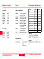
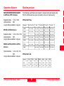
1
20
30
40
50
GPS System 500
GPS Equipment User Manual
Version 4.0
English
GPS System 500
Symbols used in this manual
Congratulations on your purchase of a new Leica
System GPS500.
The symbols used in this User Manual have the following
meanings:
DANGER:
Indicates an imminently hazardous situation
which, if not avoided, will result in death or
serious injury.
This manual contains important safety
directions (refer to chapter "Safety
directions") as well as instructions for
setting up the product and operating it.
Read carefully through the User Manual before you
switch on the instrument.
WARNING:
Indicates a potentially hazardous situation or an
unintended use which, if not avoided, could
result in death or serious injury.
Product identification
The instrument model and the serial number of your
product are indicated on the typeplate.
Enter the model and serial number in your manual and
always refer to this information when you need to contact
your agency or authorized service workshop.
GPS Receiver (SR)
Type:
Serial No.:
Terminal (TR)
Type:
Serial No.:
External Antenna (AT) Type:
Serial No.:
CAUTION:
Indicates a potentially hazardous situation or an
unintended use which, if not avoided, may result
in minor or moderate injury and/or appreciable
material, financial and environmental damage.
Important paragraphs which must be adhered to
in practice as they enable the product to be used
in a technically correct and efficient manner.
2
GPS Equipment User Manual - 4.0.0en
View of chapters
GPS Equipment User Manual - 4.0.0en
Introduction
6
System description
7
Getting started with the new Survey equipment
11
Getting started with the new MC equipment
25
Getting started with the new RS equipment
28
Getting started with the new GIS equipment
34
Care and Transport
43
Safety Directions
44
Technical Specifications
56
3
View of chapters
Contents
Introduction ................................................... 6
Getting started with the new RS
equipment .................................................... 28
System description ....................................... 7
RS500 - Introduction ............................................... 28
Receiver Hardware ................................................. 29
GPS Receiver ........................................................... 7
Receiver Hardware ................................................... 8
Setting up the RS equipment .................................... 29
Basic operating procedures ...................................... 32
Charge the Batteries ................................................... 8
Set Up the Equipment ................................................. 9
Getting Started with the new GIS
equipment .................................................... 34
Post-processing software ....................................... 10
Getting started with the new Survey
equipment .....................................................11
Introduction ............................................................. 34
Receiver Hardware ................................................. 35
SKI-Pro (SKI-Pro-L1) post-processing software ...... 11
Receiver Hardware .................................................. 11
GS50 / GS50+ Sensor .............................................. 35
QuickStart Tutorial - GIS Data Collection .................. 36
Measuring with the default configuration ................... 12
Processing the data in the SKI-Pro software .......... 23
Care and Transport ..................................... 43
Getting started with the new MC
equipment .................................................... 25
Transport ................................................................ 43
Storage ................................................................... 43
Cleaning and drying ................................................ 43
MC500 - Introduction .............................................. 25
Configure by TR500 ............................................... 26
Configure through OWI .......................................... 27
Contents
4
GPS Equipment User Manual - 4.0.0en
Contents, continued
Safety Directions ......................................... 44
Intended use of instrument ..................................... 44
Permitted uses .......................................................... 44
Prohibited uses ......................................................... 44
Limits of use ........................................................... 45
Responsibilities ...................................................... 45
Hazards of use ....................................................... 46
Main hazards of use .................................................. 46
Electromagnetic Compatability (EMC) ...................... 51
FCC statement (applicable in U.S.) ........................... 54
Technical Specifications ............................. 56
Tracking Characteristics: SR520, SR530, MC500,
RS500, GS50+ .......................................................
Tracking Characteristics: SR510 / GS50 ................
GPS Antennas ........................................................
Equipment weights .................................................
Power .....................................................................
Environmental Specifications ..................................
Separation distances ..............................................
Baseline precision ..................................................
GPS Equipment User Manual - 4.0.0en
56
57
57
58
58
58
59
59
5
Contents
Introduction
Leica GPS System 500 comprises of
GPS receiver hardware and PC
based software for GPS Surveying
and related applications.
The main components are:
• GPS Receiver: Receive the
satellite signals.
• GPS Terminal: Keyboard and
Display device to steer the
Receiver
• Post-processing software: Used
to process GPS data.
All of the instructions you
need in order to operate your
GPS system to a basic level
are contained in this user
manual.
Introduction
In the "Technical Reference Manual"
and SKI-Pro Online Help (available in
English, French and other selected
languages only), there are more
detailed descriptions of special
software/hardware settings and
software/hardware functions. These
are intended for technical specialists.
The Technical Reference Manual is
available as an electronic PDF
document only. This document can
be found on the SKI-Pro installation
CD. For more information refer to the
file \MANUALS\README.TXT on the
SKI-Pro installation CD.
6
GPS Equipment User Manual - 4.0.0en
System description
GPS Receiver
The GPS Receiver receives the GPS
signal from the NAVSTAR satellites
and calculates a range to all visible
satellites.
There are various types of Receivers
available:
GS50 - 12 L1 channels, carrier aided
code and DGPS ability.
GS50+ - 12 L1, 12 L2 channels,
code and phase, RTK capable
SR510 - 12 L1 channels,
code and phase
SR520 - 12 L1, 12 L2 channels,
code and phase
See section 8 for technical
specifications.
SR530 - 12 L1, 12 L2 channels,
code and phase, RTK capable
The SR520, SR530, MC500
and RS500 Receivers use
the GPS P-code signal, which by
U.S. policy is liable to be switched off
without notice. Phase measurements
on L2 are ensured however as these
Receivers automatically switch to
patented tracking techniques.
MC500 - 12 L1, 12 L2 channels,
code and phase, RTK capable
RS500 - 12 L1, 12 L2 channels,
code and phase
GPS Equipment User Manual - 4.0.0en
The SR510 utilises the AT501
Antenna. The SR520, SR530 and
GS50+ typically utilise the AT502
Antenna but may also use the AT503
and AT504 Antennas. The MC500
utilises the AT502 Antenna but may
also use the AT503 and AT504
Antennas for GPS Reference Station
use. The RS500 utilises the AT503 or
AT504 Antennas but may also use the
AT502 Antenna. The GS50 may use
either the AT501, RTB or RTS
Antennas.
7
System description
Receiver Hardware
Charge the Batteries
In most cases, a short introduction in
the use of the Receiver and Terminal
will be provided by the local Leica
representative. If this is not the case
proceed as outlined in the following
sections.
Charge the batteries with the Leica
battery charger provided. GEB121,
GEB70 or GEB71 batteries may be
used to power the GPS equipment.
Alternatively refer to the Technical
Reference PDF-manual available on
the SKI-Pro Installation CD.
WARNING:
The battery chargers are
intended for indoor use only.
Use a battery charger in a dry room
only, never outdoors. Charge batteries
only at an ambient temperature
between 10°C and 30°C
(50°F to 86°F).
We recommend a temperature of 0°C
to +20°C (32°F to 68°F) for storing the
batteries.
The GEB121 batteries may be
charged using GKL111 or GKL122
chargers.
Charger
GKL122
1100Z07new
GEB70 or
GEB71
Adapter plate
GDI121
System description
8
Use only the Leica batteries,
chargers and accessories,
or accessories recommended by
Leica.
The GEB70 and GEB71 batteries may
be charged using GKL122 (with
charging cables), GKL23 or GKL22
chargers.
Refer to the appropriate manual when
using the chargers.
GPS Equipment User Manual - 4.0.0en
Set Up the Equipment
To attain full battery capacity
for new GEB121 batteries, it
is essential to repeat between three
and five complete charge/discharge
cycles.
Successful GPS surveys require
undisturbed satellite signal reception.
This means that GPS Receivers should
be set up in locations which are free of
obstructions. No obstacles like trees,
buildings, mountains, etc. should block
the line between the GPS antenna and
GPS satellites. This holds true in
particular for the Receiver which serves
as the reference.
For static and rapid static surveys,
the antenna must be kept perfectly
steady throughout the whole occupation of a point. This means that the
AT501 or AT502 antenna will usually
be put on a tripod.
Center and level the tripod precisely
above the survey marker. Place and
lock the carrier in the tribrach. Mount
the antenna onto the carrier.
Connect the antenna to the sensor
using the antenna cable.
GPS Equipment User Manual - 4.0.0en
9
Plug two camcorder batteries into the
backside of the sensor. Alternatively
or in addition you might want to power
the sensor externaly. In this case
connect a GEB71 battery to the
PWR- port of the sensor.
Attach the TR500 terminal to the
sensor, either directly or via a connection cable by plugging it into the
TERMINAL-port on the sensor.
Insert a PC-card into the sensor.
Lock the lid carefully after
insertion of the card in order
to prevent water and dust from getting
inside the sensor.
Use the hook on the backside of the
sensor to hang it on one of the tripod
legs. Alternatively you may want to
leave the sensor inside the shipping
case.
Your System 500 sensor is now fully
ready for operation.
System description
Post-processing software
The Post-processing software is used
to process the observations taken by
the Receiver in order to compute
baselines and coordinates.
SKI-Pro Static Kinematic software is
the standard post-processing software
for dual-frequency receivers. SKI-ProL1 is for single frequency receivers.
The user interface for SKI-Pro and
SKI-Pro - L1 software packages are
identical.
System description
10
GPS Equipment User Manual - 4.0.0en
Getting started with the new Survey equipment
SKI-Pro (SKI-Pro-L1) post-processing software
Receiver Hardware
In most cases, the software will be
installed by the local Leica representative and a short introductory
course will be given.
In most cases, a short introduction in
the use of the Receiver and Terminal
will be provided by the local Leica
representative. If this is not the case
proceed as outlined in the following
section.
Should this not be the case, install
the software as follows:
1. Insert the CD-ROM into the CD
drive of your PC.
2. Select Install SKI-Pro from the
menu.
The software contains a comprehensive Online Help System. This Help
System is intended to replace the
function of a printed manual. If
required you may print out the entire
help for use as a hard copy reference
manual.
As a first step in getting familiar with
the software read the booklet Getting
Started with SKI-Pro delivered with
the SKI-Pro software package.
Alternatively refer to the Technical
Reference PDF-manual available on
the SKI-Pro Installation CD.
3. Follow the instructions given by the
installation shield.
GPS Equipment User Manual - 4.0.0en
11
Getting started with the new Survey equipment
Measuring with the default configuration
Step 1: Power on
Step 2: Study the Icons
Turn on the sensor by pressing the ON-button on the terminal. One of the
following two screens will appear on the display:
Most important at this stage is the top
part of the screen which contains
several symbols (icons) which
indicate the current system status.
Battery
Accuracy
GSM
Accuracy No.
No.visible
visible
GSM
Satellites
Status
Status
Status
Battery
Status
Satellites
Status
No.
Satellites
Local
Memory
StatusPosition used on L1/L2
Time
Status
Mode
Position
No. Satellites
MemoryAuto Position
Local
Radio
Mode
used on
L1/ Observation
StatusRecording
Time
Status
Recording Status
L2
Radio Status
Observation Auto
Position
Status Recording
Recording
Status
Status
Getting started with the new Survey equipment
12
GPS Equipment User Manual - 4.0.0en
Measuring with the default configuration, continued
Upon power on you will first recognize the Number of visible Satellites icon, indicating the number of
satellites which are theoretically
visible at the current location and
time. Usually this number varies
between 4 and 9, depending on the
satellite geometry and elevation
mask.
Next to this symbol you find the
Number of Satellites used on L1 /
L2 icon, indicating the number of
satellites currently tracked either on
L1 or on L2.
Upon power on you will read L1: 0,
L2: 0. It will take about 30 seconds
for these numbers to start changing
until they reach the number of satellites visible.
GPS Equipment User Manual - 4.0.0en
Both Number of visible satellites and
Number of satellites used icons will
change from time to time, reflecting
changes in the satellite geometry due
to either the rise of new satellites or
the setting of descending satellites.
Once a minimum of 4 satellites is
tracked the sensor can start computing a position. As soon as a position
is available it will be indicated by an
icon on the far left of the status line.
Since for postprocessing surveys no
realtime link will be used, the icon will
always indicate the availability of an
autonomous position (navigated
position) with an accuracy of about
10 meters (with Selective Availability
switched off).
13
As soon as the Position Mode icon
becomes visible the sensor is in a
stage where practical operation can
commence.
If the Position Mode icon does not
become visible even after one or two
minutes then the sensor is still not
tracking satellites. If the Number of
satellites used is still zero, please
check whether the antenna cable is
connected properly to both the
sensor and the antenna.
If the Number of satellites used
differs from the Number of visible
satellites make sure you place the
antenna in an open area without
obstructions, since any obstacle will
block the view of satellites.
Getting started with the new Survey equipment
Measuring with the default configuration, continued
The Battery Status icon at the right
side of the icon line shows from
which source the sensor is currently
powered. A and B indicate the
internal batteries, E an external
battery source. The symbol also
indicates the voltage level of the
currently used battery in 4 different
stages from "full" (fully black) to 2/3
to 1/3 and "almost flat" (white colour).
You cannot proceed from
here if no memory device is
available. Insert a PC-card
otherwise no GPS survey can be
carried out.
Before you start logging data you
may want to (re-)format your PC-card
or your internal memory.
This step is only necessary if a
completely new PC-card is used or if
all existing data needs to be deleted!
The Memory Status icon indicates
whether memory for logging data is
available or not. Options are either a
PC-card or internal memory. If a PC
card is available and configured for
use then at this stage an arrow
indicates the fact that it is safe to
remove the PC-card from the sensor.
The little bar on the right side indicates the available memory on either
the PC-card or the internal memory.
Getting started with the new Survey equipment
Step 3 (optional):
Format your memory card
Press 4 on the terminal or use the
Cursor key to highlight the line 4
Utilities, then press ENTER; alternatively press F1 CONT.
(If only lines 1 to 3 are visible at this
stage press F4 SHOW first).
Then press 2 to get access to the
Format Memory Module panel, or
alternatively use the cursor key to
navigate to 2 Format Memory
Module and press ENTER; again
alternatively press F1 CONT.
14
GPS Equipment User Manual - 4.0.0en
Measuring with the default configuration, continued
You are now in the Utilities \ Format
Memory Module panel:
If you want to format the PC-card just
press F1 CONT to format the card. If
you want to format the internal
memory press ENTER. A list-box
opens which allows you to select the
internal memory.
Use the cursor key to highlight
Internal, then press ENTER. Then
press F1 CONT in order to start the
formatting process of the internal
memory.
By activating the format
command all data will be
lost! Make sure that all
important data which resides on the
PC-card is properly backed-up before
reformatting the card. If you want to
reformat the internal memory make
sure that all important data is first
transferred to the PC.
If you realise that you do not want to
format the memory device, simply
press ESC instead of F1 CONT. This
key-stroke brings you always a step
back into the previous panel without
execution of any command.
Once the formatting of the card is
completed the MAIN\ panel will
appear.
GPS Equipment User Manual - 4.0.0en
15
Getting started with the new Survey equipment
Measuring with the default configuration, continued
Step 4: Begin a Survey
Enter the Survey operation by either
pressing 1 in the Main\ panel or by
first navigating to 1 Survey via
cursor keys and then pressing
ENTER or F1 CONT.
The following panel will appear:
Some basic decisions have to be
made in this panel:
Which configuration set should be
activated, which job the raw data
should be stored and which antenna
set-up should be used.
A Configuration Set (Config Set) is a
collection of sensor parameters
needed to perform a certain operation, like data recording rates, point id
templates, data formats, antenna
types, coding methods, etc.
For static survey you should select
the PP_STAT configuration set. You
can make this selection either by
using the cursor left key to toggle
between all available configuration
sets until PP_STAT appears or you
can highlight the input field and press
ENTER. Then a list box comes up
showing all available sets:
Several default configuration sets
exist which cover standard survey
scenarios. How to create new configuration sets is described in a later
chapter as well as in the Technical
Reference Manual.
Getting started with the new Survey equipment
16
GPS Equipment User Manual - 4.0.0en
Measuring with the default configuration, continued
Now use the cursor up or cursor
down key on the terminal to highlight
the PP_STAT line. Then press
ENTER or F1 CONT.
Use the cursor up or cursor down key
to highlight the input field for jobs.
Then press ENTER. The following
listbox will appear:
Now press F2 NEW. The following
panel appears:
Jobs are used to organise and
structure the data you collect in the
field. Jobs can comprise an unlimited
number of points together with all
related information (raw measurements, codes, point annotation, etc.).
It is recommended that a new job is
created whenever a new project is
started.
Upon formatting the memory device
(i.e. PC-card or internal memory) a
default job is automatically created.
You can either use this job straight
away or you can create your own job
by doing the following:
GPS Equipment User Manual - 4.0.0en
17
Getting started with the new Survey equipment
Measuring with the default configuration, continued
You can now enter a name for a new
job; press ENTER upon completing
the input of the name. Input fields for
description and creator are optional
and can be left blank.
By default the new job will be assigned to the PC-card. If needed this
can be changed to Internal by
toggling the Device input field to
Internal.
As an example we can create a new
job called Test:
Pressing F1 CONT confirms the
creation of a new job name and its
location. Press ESC if you want to
leave this field without creating a new
job. Pressing F6 QUIT has the same
effect.
Getting started with the new Survey equipment
18
After pressing F1 CONT the list of
available jobs is updated and now
shows the job Test:
GPS Equipment User Manual - 4.0.0en
Measuring with the default configuration, continued
Now press F1 CONT to confirm the
selection of the newly created job.
Now all required settings for a static
survey are made. The Survey \ Begin
panel looks as follows:
Finally you have to select the antenna type and and antenna setup
which you are using. Normally this
will be AT502 on tripod (or AT501 on
tripod in case of a SR510 sensor).
This selection is made in the usual
way: first use the cursor down key to
get this input field highlighted. Then
use the cursor left or right key to
toggle between all available types
until the right one appears. Alternatively you can press the ENTER key
to get a listbox from which the choice
can be made.
GPS Equipment User Manual - 4.0.0en
Step 5: Logging raw data
We are now within the main Survey
panel. After the above configuration
setup, the main Survey panel will
look as follows:
Press F1 CONT to finish this start-up
sequence.
19
Getting started with the new Survey equipment
Measuring with the default configuration, continued
It is time to check again the icons on
the top of the display: The Position
Mode icon should be available, the
Position Mode icon still indicates
"moving" , the Number of visible
satellites icon should display a
number greater or at least 4, and the
number of used satellites should be
identical to the number of visible
satellites.
As soon as you are tracking a minimum of 4 satellites, the position icon
is visible and the antenna is placed
correctly above the survey marker,
you should press F1 OCUPY.
This activates logging of raw data
and the screen changes accordingly:
The position mode icon has changed
to static, indicated by a symbol of a
tripod.
A new icon is now displayed which
indicates that raw data is being
logged.
Raw data (containing pseudorange
and phase measurements to each
tracked satellite) is logged at
predefined intervals (usually every 10
to 15 seconds, depending on the
Observation Recording Rate set in
your currently used configuration
set):
Enter a Point Id by filling in the input
field. If you make a typing error
correct the mistake by pressing the
CE key (Clear Entry). Complete the
input by pressing ENTER.
Getting started with the new Survey equipment
20
GPS Equipment User Manual - 4.0.0en
Measuring with the default configuration, continued
Now use the height hook to determine the height of the antenna above
the survey marker. Insert the height
hook into the carrier and measure the
height between the white mark at the
bottom of the height hook and the
survey marker.
Enter this reading into the Ant
Height field. Since the antenna you
have selected is "AT502 Tripod"
(AT501 Tripod in case of a SR510
sensor) the offset from the height
hook to the phase center of the
antenna is automatically taken care
of.
The Static observation counter
(Static obs) will now go up every 10
seconds (because this is the default
logging interval).
The displayed GDOP value indicates
the current satellite geometry; the
lower the value the better.
The antenna must not be
moved while data is logged,
otherwise the quality of
post-processed coordinates will be
impaired !
The PC-card must not be
removed while in the Survey
panel. If the card is taken
out of the receiver all stored data
might get corrupted, preventing SKIPro from successfully reading the
data on the card.
The TR500 terminal may now be
disconnected. This will have no effect
on the survey ! Datalogging will
continue. When reconnecting the
terminal the same panel will reappear.
These are the only two inputs needed
for surveying a point.
GPS Equipment User Manual - 4.0.0en
21
Getting started with the new Survey equipment
Measuring with the default configuration, continued
Datalogging should continue depending on your observation plan: a
receiver used as reference has to run
permanently until all rover site occupations are completed. If a unit is
operated as a roving receiver the site
occupation time depends mainly on
the baseline length and your accuracy requirements. See General
Guide to Static and Rapid Static for
details.
Once a sufficient amount of raw data
has been collected the survey of the
point can be completed by pressing
F1 STOP.
The screen is altered as follows:
Step 6: Ending a Survey
You can now quit the survey operation panel by pressing SHIFT F6
QUIT. This brings you back to the
main menu.
The STORE key has become active,
and you still have the chance to
check and correct the entered point
id and the antenna height.
Conclude the survey sequence by
again pressing F1 STORE.
After pressing the STORE key all
related information will be stored in
the currently used job (point id,
antenna heights, etc.)
Pressing SHIFT F6 will
always allow you to terminate the survey operation,
even during a site occupation. In this
case you will lose all data collected
since pressing OCUPY.
As soon as you are back to the main
menu the PC-card may be removed.
This is indicated by the PC-card icon
in the status line which contains an
arrow:
You can now switch off the receiver.
Once power is off disconnect all
cables and put all equipment back
into the shipping case.
Getting started with the new Survey equipment
22
GPS Equipment User Manual - 4.0.0en
Processing the data in the SKI-Pro software
You might now move to another site
and repeat the procedure outlined in
this chapter. Once your fieldwork is
finished you can proceed by processing the collected data in SKI-Pro in
order to get accurate baseline results.
During operation of the
GPS System 500 the PCCard memory card will
become warm. This is
normal.
In most cases, a short introductory
course to the software will have been
given by the local Leica representative.
To import and process the data
proceed as follows:
The data is then read by SKI-Pro
and copied to the project related
database.
Repeat the import process for
each sensor which was involved in
the fieldwork of your project.
• Switch on the computer, start
Windows, start SKI-Pro.
• Import the data
For each sensor you must import
the data into SKI-Pro
Select "Import GPS Raw Data"
from the toolbar. Follow the
instructions that appear on the
screen.
You may wish to create a new
project before storing the data on
the PC.
GPS Equipment User Manual - 4.0.0en
23
Getting started with the new Survey equipment
Processing the data in the SKI-Pro software, continued
• Process the data
Select the Data-Processing view of
the project you want to process.
The data which was previously
reported appears on the screen in
both a text and also graphical
format.
When the computation is finished
activate the "Results" view of your
project and examine the
information which is made
available, including the logfile.
You must tell the program which
station is the Reference and which
points are Rover. Click on the
graphical observation bars using
the right mouse button and select
either Reference or Rover.
As soon as a Reference and a
Rover occupation is selected the
baseline between the two points
can be computed. Click the
"Compute" button on the tool bar
to start processing the baseline.
Getting started with the new Survey equipment
24
GPS Equipment User Manual - 4.0.0en
Getting started with the new MC equipment
MC500 - Introduction
The MC500 is a ruggedized System
500 (SR530) which has been built for
the high vibration and shock
environments.
For example, the MC500 can be
configured with the TR500 Terminal,
all cables are compatible, data can
be stored and processed in Ski-Pro.
Features that are unique to the
MC500 include:
Due to its rugged design, the MC500
is ideal for Machine Guidance
applications.
•
•
•
•
•
Ruggedized housing
Standard Shock Isolators
Higher vibration and shock
specification than System 500
Survey equipment.
Ruggedized lemo cable
connectors
External Power Source
The MC500 is a key component of
the Leica Dozer 2000 Machine
Guidance System from Leica.
System Configuration
The MC500 receiver can be
configured and operated in two ways.
•
Via the TR500 Terminal.
•
Via the Outside World Interface
(OWI) protocol.
These configuration options are
described in the following sections.
As the MC500 is a fully compatible
System 500 GPS receiver, it is
capable of the full functionality of the
SR530 dual frequency RTK receiver.
Figure MG.01 MC500 GPS Receiver
GPS Equipment User Manual - 4.0.0en
25
Getting
started
with
thethe
new
Survey
equipment
Getting
started
with
new
MC equipment
Configure by TR500
The TR500 Terminal can be used to
configure the MC500, check the
status of the observations and
satellites in the same way as it is
used to configure the System 500
survey receivers.
When using the TR500 to configure
the MC500, the MC500 must be
configured from an external power
source, and the TR500 connected to
the Terminal Port of the MC500 via a
standard Leica data cable.
A block diagram of this configuration
is shown in Figure MG.02.
Please refer to the System 500 part
of the User Manual fro instructions to
use the TR500 to configure the
MC500 receiver.
Figure MG.02
Survey
equipment
Getting started with the new MC
equipment
26
MC500 GPS Receiver configured by TR500
GPS Equipment User Manual - 4.0.0en
Configure through OWI
The MC500 can be incorporated as
an OEM product into a range of
positioning systems by third parties.
For example the MC500 can be
incorporated into Port Control Systems, Hydrographic Survey systems
and general machine guidance
systems for Construction, Mining and
Agriculture. Leica uses the MC500
as a critical component of the Dozer
2000 Machine Guidance product.
The MC500 can be configured using
an interface protocol developed by
Leica called the Outside World
Interface (OWI).
Documentation on the OWI format
can be supplied on request.
Figure MG.03 shows a typical configuration set up to enable configuration of the MC500 via OWI.
GPS Equipment User Manual - 4.0.0en
Figure MG.03
27
MC500 GPS Receiver configured by OWI
Getting
started
with
thethe
new
Survey
equipment
Getting
started
with
new
MC equipment
Getting started with the new RS equipment
RS500 - Introduction
The RS500 receiver has been designed specifically for use as a
reference station.
The RS500 uses the same housing
and meets the same technical and
environmental specifications as the
SR5xx sensors. For details please
refer to the Technical Specifications
section of this manual.
Generally, the RS500 operates in the
same manner as the SR530, but is
designed to operate for specific
reference station applications using
remote control software, i.e. Leica
Geosystems ControlStation™ software.
It supports internal logging of GPS
raw data, but can also log data from
external devices approved by Leica
Geosystems. Both GPS raw data and
external sensor data can be directly
output to an external remote control
software package.
Data Storage
The RS500 supports all standard
Leica Geosystems PCMCIA card
types. The internal memory option
may be installed as well. This enables data to be stored internally for
post-processing.
With a radio modem attached, the
receiver can be used to transmit data
for RTK operations using proprietary
as well as standard RTCM or CMR
formats. The RS500 cannot receive
Reference Station broadcasts and
therefore cannot be used as a RealTime rover receiver.
Outside World Interface (OWI)
External control of the RS500 via
remote interface is achieved through
use of the Outside World Interface
(OWI) command language. The
ASCII/NMEA type message format
from Leica as well as the compact
Leica Binary 2 format can be used.
Integration assistance and OWI
documentation is available on request
from Leica Geosystems.
Standard Features
The RS500 includes the following
standard features, which are not
available as standard in the SR5xx
sensor types:
One PPS Output port.
Two Event Input ports.
Ring Buffer logging.
Support for external sensors (Meteo/
Tilt).
Getting started
started with
with the
the new
new RS
Survey
equipment
Getting
equipment
28
GPS Equipment User Manual - 4.0.0en
Receiver Hardware
Powering the RS500
The RS500 can be powered using the
Leica standard internal Camcorder
batteries or Leica standard external
batteries for temporary use. For a
more permanent setup, a universal
100V-240VAC 50-60Hz to 12VDC
power converter is available. Alternative 12VDC power sources may be
utilised by means of a user
configurable 12VDC power cable with
in-line fuse.
Setting up the RS equipment
Power Failures
The RS500 will automatically power
itself up and return to the previous
operating mode after any temporary
power failure without user (or remote
control) interaction.
Cabling Connections / Options
Cable connections are identical to
other System 500 receivers.
Turning the RS500 On/Off
The RS500 can be powered on or off
by the TR500 Terminal, the sensor
integrated ON/OFF button or by a
remote control command (OWI).
Mounting the GPS antenna should
take into consideration environmental
conditions, structural or ground
movements, change in use of the
property or surrounding properties
and tree growth. These may impact
the future performance of the GPS
Reference Station.
Using the ON/OFF button
will reset the receiver. All
programmed outputs, data
logging parameters and
interface configuration
options that have been set
by OWI commands will be
lost.
GPS Equipment User Manual - 4.0.0en
The RS500 is specifically designed as
a long term GPS Reference Station.
The AT502, AT503 or AT504 antenna
should be mounted on a stable
structure with a very clear view of the
sky. SKI-Pro should be used to
produce a satellite visibility plot for the
location using an up to date almanac.
Any potential obstructions to satellite
signals should be measured by
clinometer and compass and compared with the satellite visibility plot
and proposed elevation mask to
assess their potential impact to the
usefulness of the location as a GPS
Reference Station.
29
Getting
started
withwith
the the
newnew
Survey
equipment
Getting
started
RS equipment
Setting up the RS equipment, continued
The antenna mounting point should
have a 5/8" thread and an unambiguous reference point both horizantally
and vertically to which the antenna
phase centre can be referenced to.
The equipment should ideally be in a
secure location with a reliable power
supply. An uninterruptable power
supply with sufficient backup capacity
for the local power conditions is
recommended. The equipment
should be protected against lightning
or static electrical discharge as
discussed further within the Safety
Directions of this manual.
Connect the antenna to the sensor
using the supplied antenna cable.
Kinks, cut and crushed areas of the
antenna cable may degrade signal
quality and strength. It is recommended that the antenna cable be
protected from long term damage.
Connect a 12VDC power supply to
the PWR port of the RS500, or insert
the internal camcorder batteries for
short term operation.
For general configurations, system
data transfers from/to the PC card
and viewing status information attach
the TR500 terminal to the sensor,
either directly or via a connection
cable by plugging it into the TERMINAL port on the sensor.
For configuration and operation like
data logging and real time data
transmission connect the sensor to a
PC using the data cable (Art. No. 560
254). The PC should be running an
appropriate application program such
as Leica Geosystems
ControlStation™.
Lock the lid carefully after
insertion of the card in order
to prevent water and dust
from getting inside the
sensor.
Use the hook on the backside of the
sensor to hang it on one of the tripod
legs or leave the sensor inside the
shipping case. The mounting bracket
(Art. No. 722 105) may be used to
attach the RS500 receiver firmly to a
bench, table or wall.
Your RS500 sensor is now fully ready
for operation.
See Fig. RS.01 for a basic connection
scheme.
Insert a PC-card into the sensor, if no
internal memory option is installed.
Getting started
started with
with the
the new
new RS
Survey
equipment
Getting
equipment
30
GPS Equipment User Manual - 4.0.0en
Figure RS.01 Basic connection scheme
GPS Equipment User Manual - 4.0.0en
31
Getting
started
with
thethe
new
Survey
equipment
Getting
started
with
new
RS equipment
Basic operating procedures
The RS500 can be operated either
with the TR500 Terminal or by remote
control. However, the TR500 cannot
be used for running a survey, stakeout or any of the other applications
available for System 500.
Used with an RS500, the Terminal
provides the general functionality to
set certain operation parameters, port
configurations and all transfer capabilities, including the upload of new
firmware. Via the STATUS hard key
all status information is available.
For the majority of applications, the
RS500 has to be operated using
Leica Geosystems ControlStation™
or other appropriate reference system
control software.
Using the RS500 with the TR500
Step 1: Power on
Turn on the sensor by pressing the
ON-button on the terminal. The
following screen will appear on the
display:
The RS500 CONFIG and STATUS
menus do only show those options
that are relevant to the operation of
an RS500.
Full details on the RS500 unique
operational procedures are given in
the Technical Reference Manual
(PDF Document), which is contained
on the SKI-Pro or ControlStation™
release CD.
Step 2: Study the Icons
The RS500 has the same main menu
panel as the SR5xx sensors except
that the first 3 menu options are
removed. It is also not possible to
perform the real time configuration for
the RS500. This needs to be done
using remote control software. All
data management, job control and
sensor status operations required by
an RS500 user are possible using the
menu options shown above.
Getting
equipment
Getting started
started with
with the
the new
new RS
Survey
equipment
32
For a detailed description refer to
Step 2 of the chapter Getting started
with the new Survey equipment Measuring with the default configuration on pp. 11-13.
GPS Equipment User Manual - 4.0.0en
Basic operating procedures, continued
Step 3 (optional):
Format your memory card
Step 4:
Connecting the sensor to the PC
Step 5(optional):
Connecting the sensor to a Radio
For a detailed description refer to
Step 3 of the chapter Getting started
with the new Survey equipment Measuring with the default configuration on pp. 13-14.
For normal operations the sensor will
be connected to a PC using the
RS232 data download cable
(560254).
The RS500 has the ability to transmit
real-time GPS data out of Port 1 and
Port 3 of the GPS sensor via the
radio interface cable (721961) to a
Leica supplied radio unit.
Connect the cable to the sensor
remote control port (by default the
Terminal port) and the available Com
port of the PC.
Configuration of the remote port on
the sensor is described in the Technical Reference Manual.
Radio installation and connection
instructions are provided with Leica
supplied radio units.
Unauthorised radio units
should not be connected to
the RS500 sensor unit.
Operation of the RS500 from a PC
requires one of the Leica reference
station software programs which are
supplied with operating instructions.
GPS Equipment User Manual - 4.0.0en
33
Getting
started
with
thethe
new
Survey
equipment
Getting
started
with
new
RS equipment
Getting Started with the new GIS equipment
Introduction
“Getting Started with New GIS Equipment” is designed to help get the
beginning user up and running with
their new Leica GS50 and GS50+.
For more information about setup,
features and operations of the GS50,
please refer to the “Getting Started
with the GS50 / GS50+ Sensor”
manual.
The Leica GIS DataPRO system is
composed of both hardware and
software components.
The hardware consists of the GS50
sensor, TR500 terminal and antenna.
This is used in the field to collect and
record spatial (position) and nonspatial attributes.
Hardw
are
Hardware
GS50 / GS50+
TR500
Antenna
Leica GIS
Solution
Software
GIS DataPRO
The GIS DataPRO office software is
comprised of a GPS post-processing
system and data editing functionality
which works in the native ESRI
shapefile format.
GIS DataPRO Post-processing
software
GIS DataPRO is used for data
collection preparation and data post
processing. Please refer to the
“Getting Started with the GIS
DataPRO Office Software” User
Manual for more details.
Getting started
started with
with the
the new
new GIS
Survey
equipment
Getting
equipment
34
To install the GIS DataPRO software:
1.Insert the CD-ROM into the CD
drive of your PC.
2.Execute the “Setup” command.
3.Follow the instructions that appear
on the screen.
Both a hardware and software user
manual can be found on the CD in
PDF format. The software itself
contains a comprehensive online
Help System.
After the data is collected in the field,
the GIS DataPRO office software
allows you to import, edit and export
the data to your GIS. The software
can also be used to design codelists
which allow you to customize the field
data collection process to suit your
needs. To learn more about the GIS
DataPRO office software, please
consult the “Getting Started with the
GIS DataPRO Office Software User
Manual”.
GPS Equipment User Manual - 4.0.0en
Receiver Hardware
GS50 / GS50+ Sensor
The GS50 / GS50+ sensor consists
of both a handheld terminal (TR500),
and the GPS receiver itself. The GPS
receiver receives the GPS signal from
the NAVSTAR satellites and calculates a range to the satellites that are
visible.
The GS50 is a 12-channel L1 code
and phase GPS receiver. The standard GS50 does not record phase
measurements for post processing
purposes. Phase measurements are
used internally to smooth
pseudorange measurements for
higher code positioning. Phase
measurement recording for post
processing is available as an option.
The GS50+ is a 12-channel L1, 12channel L2 code and phase GPS
receiver. The standard GS50+
records code and phase measurements for post processing and / or
uses DGPS for real-time code-only
positioning. RTK is available as an
option.
There are three antennas available
with the GS50:
There are three antennas available
with the GS50+:
• AT501 – tracks L1 only (GS50).
• AT502 – tracks L1 and L2. Mainly
used for Rovers and References.
• RTB Combined Antenna - tracks
L1 and RTCM differential signal
from public and private beacon
infastructure.
• RTS Combined Antenna - tracks
L1 and differential signals from
Racal DGPS Satellite systems.
GPS Equipment User Manual - 4.0.0en
35
• AT503 – Choke Ring Antenna
tracking L1 and L2. Mainly used for
Reference stations.
• AT504 – JPL Design Choke Ring
Antenna tracking L1 and L2. Mainly
used for Reference stations.
Getting
started
with
thethe
new
Survey
Getting
started
with
new
GIS equipment
QuickStart Tutorial - GIS Data Collection
The QuickStart Tutorial will guide you
through a typical data collection
session.
Each step will indicate which panel
you should be viewing by displaying
the menu title in brackets (i.e. MAIN\
for the main menu panel).
Step 1: Beginning GIS Data Collection (MAIN\)
Turn on the sensor by pressing the
ON-button on the terminal. The
following panel will appear:
This is the main data collection panel.
Pressing ESC will take you to the
main menu:
This number is based on the GPS
almanac saved in the sensor and the
last computed position. This number
does not indicate the number of
satellites the receiver is tracking.
From the main menu, entering ‘1’ on
the keypad, or highlighting GIS Data
Collection using the cursor keys and
then pressing ENTER or F1 CONT
will bring you back to the main data
collection panel.
Upon power on you will see the
“Number of visible Satellites” icon,
indicating the number of satellites
which are theoretically visible at the
current location and time.
Usually this number varies between 4
and 9, depending on the satellite
geometry.
Getting
equipment
Gettingstarted
startedwith
withthe
thenew
newGIS
Survey
equipment
36
Next to this symbol you’ll find the
“Number of Satellites used on L1”
icon, indicating the number of satellites currently tracked on L1.
On initial start-up, this number will
read 0 since it takes about 30 seconds to start tracking satellites.
Both “Number of visible satellites” and
“Number of satellites used” icons will
change from time to time, reflecting
changes in the satellite geometry due
to either the rise of new satellites or
the setting of descending satellites.
GPS Equipment User Manual - 4.0.0en
QuickStart Tutorial - GIS Data Collection, continued
Position Fix Indication
The sensor will compute a 2Dposition once 3 satellites are tracked.
A 3-D position will be computed.
If the accuracy icon does not become
visible even after one or two minutes
then the sensor is still not tracking
satellites. One reason for this is the
receiver receiving signals at a location more than 500km from the
startup position. If this is the case,
then the receiver will download a new
almanac. This will take about 15
minutes. Another reason for the
receiver not tracking is a faulty
antenna cable connection. Please
check whether the antenna cable is
connected properly to both the sensor
and antenna.
GPS Equipment User Manual - 4.0.0en
If you’re in an open area with no
obstructions, the “number of satellites
used” should correspond to the
“number of visible satellites”. However, in obstructed areas, such as
urban canyons or forested areas, it is
unlikely that the receiver will be able
to track all the satellites in the sky.
This is not a problem, but will degrade
the accuracy of measurements
slightly. Consequently, please keep
monitoring the accuracy icon.
Once the Accuracy Status icon
appears, data collection can begin.
Step 2: Choosing your Configuration Settings
(DATA COLL \ Begin)
Configuration Set (Config Set) is a
collection of sensor parameters
needed to perform various methods
of data collection. These include data
recording rates, data formats, antenna types, coding methods, etc.
Several default configuration sets
exist which cover standard data
collection scenarios. For information
on how to create configuration sets,
please refer to the hardware reference manual on the GIS DataPRO
software CD.
If no real time differential corrections
are used (i.e. you do not have the
RTCM differential beacon module
attached to the sensor), you should
select the GIS_PP (PP = Post
Processing) configuration set.
37
Getting
started
with
thethe
new
Survey
equipment
Getting
started
with
new
GIS equipment
QuickStart Tutorial - GIS Data Collection, continued
You can make this selection either by
using the “cursor left” key to toggle
between all available configuration
sets until PP_GIS appears or you can
highlight the input field and press
ENTER. Then a list box comes up
showing all available sets:
Step 3: Choosing your codelist
(DATA COLL \ Begin)
A codelist is simply a list of codes or
features. Codes are the building
blocks of the codelist and may be
thought of as features.
You can now enter a name for a new
job; press ENTER upon completing
the input of the name. Input fields for
description and creator are optional
and can be left blank.
As an example we can create a new
job called “Test”:
Now use the cursor up or cursor
down key on the terminal to highlight
the PP_GIS line. Then press ENTER
or F1 CONT.
Getting
equipment
Getting started
started with
with the
the new
new GIS
Survey
equipment
Codelists are selected as follows: first
use the cursor down key to get this
input field highlighted. Then use the
cursor left key to toggle among the
several options until the correct one
appears. Alternatively you can press
the ENTER key to get a listbox from
which the choice can be made, or a
new codelist can be created.
Please note that you must select a
codelist in order to collect data.
38
GPS Equipment User Manual - 4.0.0en
QuickStart Tutorial - GIS Data Collection, continued
Creating a new codelist
From the codelist menu box, press F2
NEW to create a new codelist name.
The following panel appears.
GPS Equipment User Manual - 4.0.0en
Step 4: Choosing your antenna
type
(DATA COLL \ Begin)
As an example, we will create a
codelist called ‘Electric’. Enter the
word Electric in the Name input field
and press ENTER. Press F1 CONT
to return to the codelist menu box.
The Electric codelist now appears in
the menu box. Make sure the Electric
codelist is highlighted, and press
ENTER.
39
Finally you have to select the antenna
setup which you are using. For L1
post processing, this will normally be
the AT501. For real time differential, it
will normally be the RT combined
antenna and for L1 + L2 post
processing it will be the AT502
antenna. In this example, the selection indicates the RT combined.
This selection is made in the usual
way: first use the cursor down key to
get this input field highlighted. Then
use the cursor left key to toggle
among the several options until the
correct one appears. Alternatively you
can press the ENTER key to get a
listbox from which the choice can be
made.
Now all required settings for a typical
data collection session are made.
The Data Coll \ Begin panel looks the
following:
Getting
started
with
new
GIS equipment
Getting
started
with
thethe
new
Survey
equipment
QuickStart Tutorial - GIS Data Collection, continued
Creating codes
If your codelist contains no codes,
your codelist menu box looks like this:
Pressing F1 CONT finishes this startup sequence.
As an example, we will create a point
code names Pole. We will input the
following note in the note field, “Offset
to road”. The note field can be used
to describe the manner in which data
is collected for a particular code. In
this example, we are measuring the
pole location from the road. Press F1
CONT to continue.
Step 5: Selecting or creating codes
for data collection (FEATURING\)
You are now in the FEATURING\
panel. This panel allows you to select
or create codes for data collection.
Codelists can also be created using
the Codelist Manager module within
the GIS DataPRO software.
If in the previous step you selected an
existing codelist, a number of codes
appears in the codelist box. If you
created a new codelist in the previous
step, this listbox is empty.
To create a new code, press F2 CLST. Use the right or left cursor key to
select a code list. Press F3 CODES
and then F2 NEW.
Use the right or left cursor key to
choose the code type (point, line, or
polygon). Enter the name of the code,
and a note about the code (optional),
in the appropriate input fields.
Getting
equipment
Getting started
started with
with the
the new
new GIS
Survey
equipment
40
GPS Equipment User Manual - 4.0.0en
QuickStart Tutorial - GIS Data Collection, continued
Step 6: Logging point data (ATTRIBUTION\)
In this step, you will collect the spatial
attribute (position information) for
your Pole (point) code.
It is time to check again the icons on
the top of the display. The position
icon should be available, the position
mode icon still indicates “moving”, the
“number of satellites visible” icon
should display a number greater or at
least 4, and the number of used
satellites will generally be the same
as the number of visible satellites, if
you are in a relatively open area.
Pressing F4 OFFS will allow you to
enter an offset to the desired point
code. You can enter this offset in one
of four ways:
GPS Equipment User Manual - 4.0.0en
•
•
•
•
Bearing and Distance
Double Bearing
Double Distance
Backward Bearing & Distance
•
•
•
•
•
•
•
•
Leica DistoTM pro4 (distance only)
Leica DistoTM pro4 a (distance only)
Laser Ace 300
Criterion 400
Criterion Compatible
Leica Vector
Leica Laser Locator
Leica Laser Locator Plus
You can configure your GS50 /
GS50+ to interface with your laser
range finder from the
CONFIGURE\OFFSET panel. Please
see the technical reference manual
for more information.
The GS50 / GS50+ interfaces to a
number of laser range finders that will
allow you to accurately measure
offset distances and angles. The
following laser range finders are
supported:
As soon as you are tracking a minimum of 4 satellites, the accuracy icon
is visible (indicating good position
quality), and the antenna is positioned
close to the feature, you should press
F1 OCUPY.
• Leica Disto memo (distance only)
• Leica Disto pro (distance only)
This activates logging of raw data and
the panel changes accordingly.
41
Getting
started
with
thethe
new
Survey
equipment
Getting
started
with
new
GIS equipment
QuickStart Tutorial - GIS Data Collection, continued
Notice that the position mode icon
has changed to static mode, indicated
by a symbol of a tripod.
During data logging, attribute information can be entered into the appropriate input fields. In this example,
‘Utility‘ has been entered for Attrib 1.
Data collection times will
depend on the situation. If
the unit is being used as a
reference for post processing, then
data must be continually logged until
all roving receivers have stopped
collecting data. If the unit is operated
as a roving receiver the site occupation time depends mainly on the
baseline length and your accuracy
requirements.
Once a sufficient amount of raw data
has been collected, you can stop data
collection by pressing F1 STOP.
The information shown hereon is only
intended to get you up and running
with your new GIS equipment. Please
refer to the “Getting Started with the
GS50 Sensor” and “Getting Started
with GIS DataPRO” manuals for more
detailed information of your new GIS
system.
Getting
equipment
Gettingstarted
startedwith
withthe
thenew
newGIS
Survey
equipment
42
GPS Equipment User Manual - 4.0.0en
Care and Transport
Transport
Storage
Cleaning and drying
When dispatching the
instrument, always use the
complete original Leica packaging
(case and cardboard box).
Temperature limits
(-40°C to +70°C / -40°F to
+158°F) Respect the temperature
limits when storing the instrument,
particularly in summer if the
instrument is inside a vehicle.
Use only a clean, soft, lintfree cloth for cleaning.
If necessary, moisten the cloth with
pure alcohol.
Never carry the instrument loose in a
road vehicle. It can be affected by
shock and vibration. Always carry it in
its case and secure it.
When transporting the instrument by
rail, air or ship, always use the
complete original packaging (case
and cardboard box), or its equivalent,
to protect it against shock and
vibration.
GPS Equipment User Manual - 4.0.0en
Damp instruments must
be unpacked. Dry the
instrument, the case, the foam
inserts and the accessories at not
more than 40°C / 108°F and clean
them. Do not repack until everything
is completely dry.
43
Use no other liquids; these may
attack the polymer components.
Cables and plugs
Keep plugs clean and dry.
Blow away any dirt lodged in the
plugs of the connecting cables.
Unplugging connecting cables or
removing the PCMCIA card during
the measurement may cause loss of
data. Always switch off the
instrument before removing the
cables or the PCMCIA card.
Care and Transport
Safety Directions
The following directions should
enable the person responsible for the
Leica Geosystems GPS, and the
person who actually uses the
instrument, to anticipate and avoid
operational hazards.
The person responsible for the
instrument must ensure that all users
understand these directions and
adhere to them.
Intended use of instrument
Permitted uses
Prohibited uses
The Leica Geosystems GPS is
intended for the following
applications:
• Use of the product without
instruction
- Measuring and computing
coordinates using P-code and/or
C/A-code signals from NAVSTAR
GPS satellites
- Carrying out measurement tasks
using various GPS measuring
techniques
- Recording GPS and point related
data
- Computation and evaluation by
means of software.
• Disabling safety systems and
removal of hazard notices
• Use outside of the intended limits
• Opening the instrument using tools
(screwdriver, etc.), unless this is
specifically permitted for certain
functions
• Modification or conversion of the
instrument
• Use after misappropriation
• Use with accessories from other
manufacturers without the prior
express approval of Leica
Geosystems
• Inadequate safeguards at the
measuring station (e.g. when
measuring on roads)
Safety Directions
44
GPS Equipment User Manual - 4.0.0en
Prohibited uses, continued
WARNING:
Adverse use can lead to
injury, malfunction and
damage. It is the task of the
person responsible for the
instrument to inform the user
about hazards and how to
counteract them. The Leica
Geosystems GPS is not to be
operated until the user has
been instructed how to work
with it.
Limits of use
Responsibilities
See chapter "Technical
specifications".
Area of responsibility of the manufacturer of the original equipment
LEICA Geosystems AG, CH-9435
Heerbrugg, Switzerland
(hereinafter referred to as Leica
Geosystems):
Leica Geosystems is responsible for
supplying the product, including the
user manual and original
accessories, in a completely safe
condition.
Environment:
Suitable for use in an atmosphere
appropriate for permanent human
habitation: not suitable for use in
aggressive or explosive
environments.
GPS Receiver (SR) and Terminal
(TR):
Use in rain is permissible for limited
periods.
External Antenna:
Use in rain is permissible. After long
term use in this environment the
External Antenna must be checked
by a Leica Geosystems service
technician.
GPS Equipment User Manual - 4.0.0en
45
Responsibilities of the
manufacturers of non-Leica
Geosystems accessories:
The manufacturers of
non-Leica Geosystems
accessories for Leica Geosystems
GPS are responsible for developing,
implementing and communicating
safety concepts for their products,
and are also responsible for the
effectiveness of those safety
concepts in combination with the
Leica Geosystems product.
Safety Directions
Responsibilities, continued
Hazards of use
Responsibilities of the person in
charge of the instrument:
Main hazards of use
WARNING:
The person responsible for
the instrument must ensure
that it is used in accordance
with the instructions. This
person is also accountable
for the training and the
deployment of personnel who
use the instrument and for
the safety of the equipment in
use.
The person in charge of the
instrument has the following duties:
WARNING:
The absence of instruction, or
the inadequate imparting of
instruction, can lead to
incorrect or adverse use, and
can give rise to accidents with
far-reaching human, material,
financial and environmental
consequences.
Precautions:
All users must follow the safety
directions given by the manufacturer
and the directions of the person
responsible for the instrument.
WARNING:
The charger must not be
used under damp or
inclement conditions. If
moisture penetrates these
devices, the user may receive
an electric shock.
Precautions:
Use the charger only indoors, in dry
rooms. Protect them from damp. If
the devices are damp, do not use
them.
- To understand the safety
instructions on the product and the
instructions in the user manual;
- To be familiar with local regulations
relating to accident prevention;
- To inform Leica Geosystems
immediately if the equipment
becomes unsafe.
Safety Directions
46
GPS Equipment User Manual - 4.0.0en
Main hazards of use, continued
WARNING:
If you open the charger, either
of the following actions may
cause you to receive an
electric shock:
- Touching live components;
- Using the devices after incorrect
attempts to carry out repairs.
Precautions:
Do not open the charger yourself.
Only a Leica Geosystems approved
service technician is entitled to repair
it.
CAUTION:
Watch out for erroneous
measurements if the product
is defective or if it has been
dropped or has been misused
or modified.
Precautions:
Periodically carry out test
measurements and perform the field
adjustments indicated in the user
manual, particularly after the
instrument has been subjected to
abnormal use and before and after
important measurements.
WARNING:
If computers intended for use
indoors are used in the field
there is a danger of electric
shock.
Precautions:
Adhere to the instructions given by
the computer manufacturer with
regard to field use in conjunction with
Leica Geosystems instruments.
GPS Equipment User Manual - 4.0.0en
47
CAUTION:
If the accessories used with
the equipment are not
properly secured and the
equipment is subjected to
mechanical shock (e.g.
blows, falling), the equipment
may be damaged or people
may sustain injury.
Precautions:
When setting-up the instrument,
make sure that the accessories (e.g.
tripod, tribrach, connecting cables)
are correctly adapted, fitted, secured,
and locked in position. Avoid
subjecting the equipment to
mechanical shock.
CAUTION:
The receiver uses the GPS
P-Code signal, which by U.S.
policy, may be switched off
without notice.
Safety Directions
Main hazards of use, continued
WARNING:
Inadequate securing of the
survey site can lead to
dangerous situations, for
example in traffic, on building
sites and at industrial
installations.
Precautions:
Always ensure that the survey site is
adequately secured. Adhere to the
regulations governing accident
prevention and road traffic.
DANGER:
Because of the risk of
electrocution, it is very
dangerous to use poles and
extensions in the vicinity of
electrical installations such as
power cables or electrical
railways.
Safety Directions
Precautions:
Keep at a safe distance from
electrical installations. If it is essential
to work in this environment, first
contact the safety authorities
responsible for the electrical
installations and follow their
instructions.
WARNING:
If an External Antenna is not
properly fitted to the roof rack
of a vehicle it can be torn off
by mechanical shock,
vibration or wind, possibly
causing accident and injury.
CAUTION:
During the transport or
disposal of charged batteries
it is possible for inappropriate
mechanical influences to
constitute a fire hazard.
Precautions:
Use nothing other than the External
Antenna on the roof rack of a vehicle.
Secure the External Antenna
correctly to the roof rack by means of
the adapter. Leica Geosystems offers
the adapter as an accessory.
Secure the safety cord to the
External Antenna and connect the
cord to the adapter in accordance
with the instruction plate on the
adapter. Ensure that the roof rack is
correctly mounted and able to safely
carry the weight of the External
Antenna (>1kg).
Precautions:
Before dispatching the equipment or
disposing of it, discharge the
batteries by running the instrument
until they are flat.
48
GPS Equipment User Manual - 4.0.0en
Main hazards of use, continued
WARNING:
If the equipment is improperly
disposed of, the following can
happen:
- If polymer parts are burnt,
poisonous gases are produced
which may impair health.
- If batteries are damaged or are
heated strongly, they can explode
and cause poisoning, burning,
corrosion or environmental
contamination.
- By disposing of the equipment
irresponsibly you may enable
unauthorised persons to use it in
contravention of the regulations,
exposing themselves and third
parties to the risk of severe injury
and rendering the environment
liable to contamination.
GPS Equipment User Manual - 4.0.0en
Precautions:
Dispose of the equipment
appropriately in accordance with the
regulations in force in your country.
Always prevent access to the
equipment by unauthorised
personnel.
DANGER:
If the Leica Geosystems GPS
is used in exposed locations
(e.g. on masts, mountains or
buildings), it is at risk from
lightning. Danger from high
voltages also exists near
power lines. Lightning,
voltage peaks, or the
touching of power lines can
cause damage, injury and
death.
49
Precautions:
- Do not use a Leica Geosystems
GPS in a thunderstorm as you may
increase the risk of being struck by
lightning.
- Be sure to remain at a safe
distance from electrical
installations. Do not use the Leica
Geosystems GPS directly under or
in close proximity to power lines. If
it is essential to work in such an
environment contact the local
statutory regulatory bodies
responsible for electrical
installations and follow their
instructions.
Safety Directions
Main hazards of use, continued
- If a Leica Geosystems GPS has to
be permanently mounted in an
exposed location, it is advisable to
provide a lightning conductor
system. A suggestion on how to
design a lightning conductor for a
Leica Geosystems GPS is given
below. Always follow the
regulations in force in your country
with regard to grounding Antennas
and masts. These installations
must be carried out by an
authorised specialist.
- To prevent damages due to
indirect lightning strikes (voltage
spikes) cables (antenna, power
source, modem, ...) should be
protected with appropriate
protection elements (lightning
arrestor). These installations must
be carried out by an authorized,
local specialist.
Safety Directions
- Additional protection against
lightning:
If there is a risk of a thunderstorm,
or if the equipment is to remain
unused and unattended for a long
period, protect your Leica
Geosystems GPS additionally by
unplugging all systems
components and disconnecting all
connecting cables and supply
cables (e.g. Receiver - Antenna).
Suggestion for design of a
Lightning Conductor for a GPS
System
1. On non-metallic structures
Protection by Air Terminals is
recommended. An Air Terminal is a
pointed solid or tubular rod of
conducting material with proper
mounting and connection to a
conductor. The position of 4 Air
Terminals should be uniformly
distributed around the Antenna at a
distance equal to the height of the Air
Terminal.
50
The Air Terminal diameter should be
12mm for copper or 15mm for
aluminium. The height of the Air
Terminals should be 25 to 50cm. All
Air Terminals should be connected to
the down conductors. The diameter
of the Air Terminal should be kept to
a minimum to reduce GPS signal
shading.
2. On metallic structures
Protection is as described for nonmetallic structures, but the Air Terminals can be connected directly to the
conducting structure without the need
for down conductors.
GPS Equipment User Manual - 4.0.0en
Main hazards of use, continued
Electromagnetic Compatability (EMC)
Air Terminal arrangement
(plan view)
Grounding the Receiver/Antenna
1
2
3
1
The term "electromagnetic
compatability" is taken to mean the
capability of the Leica Geosystems
GPS to function smoothly in an
environment where electromagnetic
radiation and electrostatic discharges
are present, and without causing
electromagnetic disturbances to
other equipment.
4
2
5
3
1 GPS Antenna
2 Support-Structure
3 Air Terminal
GPS Equipment User Manual - 4.0.0en
1
2
3
4
5
Lightning Conductor Array
GPS Antenna
Antenna/Receiver Connection
Metallic Mast
Connection to Earth
51
WARNING:
Electromagnetic radiation can
cause disturbances in other
equipment.
Although the Leica Geosystems GPS
meets the strict regulations and
standards which are in force in this
respect, Leica Geosystems cannot
completely exclude the possibility
that other equipment may be
disturbed.
Safety Directions
Electromagnetic Compatibility (EMC), continued
CAUTION:
There is a risk that
disturbances may be caused
in other equipment if the Leica Geosystems GPS is used
in conjunction with
accessories from other
manufacturers, e.g. field
computers, personal
computers, walkie-talkies,
non-standard cables, external
batteries.
Precautions:
Use only the equipment and
accessories recommended by Leica
Geosystems. When combined with
the Leica Geosystems GPS, they
meet the strict requirements
stipulated by the guidelines and
standards. When using computers
and walkie-talkies, pay attention to
the information about
electromagnetic compatability
provided by the manufacturer.
Safety Directions
CAUTION:
Disturbances caused by
electromagnetic radiation can
result in the tolerance limits
for measurements being
exceeded.
Although the Leica Geosystems GPS
meets the strict regulations and
standards which are in force in this
connection, Leica Geosystems
cannot completely exclude the
possibility that the Leica Geosystems
GPS may be disturbed by very
intense electromagnetic radiation,
e.g. near radio transmitters, walkietalkies, diesel generators.
Check the plausibility of results
obtained under these conditions.
52
WARNING:
If the Leica Geosystems GPS
is operated with connecting
cables attached at only one of
their two ends (e.g. external
supply cables, interface
cables), the permitted level of
electromagnetic radiation
may be exceeded and the
correct functioning of other
instruments may be impaired.
Precautions:
While the Leica Geosystems GPS is
in use, connecting cables (e.g.
instrument to external battery,
instrument to computer) must be
connected at both ends.
GPS Equipment User Manual - 4.0.0en
Electromagnetic Compatibility (EMC), continued
Use of GPS System 500 with
external Radio devices or GSM
phones:
WARNING:
Electromagnetic radiation
can cause disturbances in
other equipment, in installations (e.g.
medical ones such as pacemakers or
hearing aids) and in aircraft. It can
also affect humans and animals.
Precautions:
Although the Leica Geosystems GPS
meets in combination with external
Radio devices or GSM phones the
strict regulations and standards
which are in force in this respect,
Leica cannot completely exclude the
possibility that other equipment may
be disturbed or that humans or
animals may be affected.
GPS Equipment User Manual - 4.0.0en
- Do not operate the Leica
Geosystems GPS with external
Radio devices or GSM phones in
the vicinity of filling stations or
chemical installations, or in other
areas where an explosion hazard
exists.
- Do not operate the Leica
Geosystems GPS with external
Radio devices or GSM phones
near to medical equipment.
- Do not operate the Leica
Geosystems GPS with external
Radio devices or GSM phones in
aircraft.
- Do not operate the Leica
Geosystems GPS with external
Radio devices or GSM phones for
long periods with it immediately
next to your body.
53
Safety Directions
FCC statement (applicable in U.S.)
WARNING:
This equipment has been
tested and found to comply
with the limits for a Class B
digital device, pursuant to
part 15 of the FCC Rules.
These limits are designed to provide
reasonable protection against
harmful interference in a residential
installation.
This equipment generates, uses and
can radiate frequency energy and, if
not installed and used in accordance
with the instructions, may cause
harmful interference to radio
communications.
However, there is no guarantee that
interference will not occur in a
particular installation.
Safety Directions
If this equipment does cause harmful
interference to radio or television
reception, which can be determined
by turning the equipment off and on,
the user is encouraged to try to
correct the interference by one or
more of the following measures:
Product labeling: SR510, SR520,
SR530, RS500, GS50 and GS50+
This device complies with part 15 of the FCC Rules.
Operation is subject to the following two conditions:
(1) This device may not cause harmful interference, and
(2) this device must accept any interference received,
including interference that may cause undesired
operation.
- Reorient or relocate the receiving
antenna.
- Increase the separation between
the equipment and receiver.
- Connect the equipment into an
outlet on a circuit different from
that to which the receiver is
connected.
- Consult the dealer or an
experienced radio/TV technician
for help.
WARNING:
Changes or modifications not
expressly approved by Leica
Geosystems for compliance
could void the user's authority
to operate the equipment.
54
GPS Equipment User Manual - 4.0.0en
FCC statement (applicable in U.S.), continued
Product labeling: MC500
This device complies with part 15 of the FCC Rules.
Operation is subject to the following two conditions:
(1) This device may not cause harmful interference, and
(2) this device must accept any interference received,
including interference that may cause undesired
operation.
GPS Equipment User Manual - 4.0.0en
55
Safety Directions
Technical Specifications
The Technical Specifications for
Leica GPS equipment are contained
on the following pages.
Tracking Characteristics: SR520, SR530, MC500, RS500, GS50+
Satellite Reception:
Dual frequency
Receiver channels:
12 L1 continuous tracking
12 L2 continuous tracking
L1 channels:
Carrier phase, P1 code, C/A code
L2 channels:
Carrier phase, P2 code
Carrier Tracking
L1, AS on or off:
Reconstructed carrier phase via C/A
code
L2, AS off:
Reconstructed carrier phase via P2
code
Code Measurements
L1, AS off:
Carrier phase smoothed code
measurements:
C/A code narrow correlation, P1 code
L1, AS on:
Carrier phase smoothed code
measurements:
C/A code narrow correlation,
patented P1 code-aided code
L2, AS off:
Carrier phase smoothed code
measurements:
P2 code
L1, AS on:
Carrier phase smoothed code
measurements:
Patented P2 code-aided code
L2, AS on:
Switches automatically to patented P
code-aided technique providing full
L2 reconstructed carrier phase
Technical Specifications
56
GPS Equipment User Manual - 4.0.0en
Note:
Carrier phase and code
measurements on L1 and L2
are fully independent with AS
on or off.
Satellites Tracked:
Up to 12 simultaneously on L1 and
L2.
Time to first phase measurement
typically 30 seconds.
Tracking Characteristics: SR510 / GS50
GPS Antennas
Satellite Reception:
Single frequency
AT504
Dorne & Margolin L1/L2 antenna
element with gold anodized choke
ring groundplane. Complies with IGS
type 'T' antenna. Optional protective
radome.
Receiver channels:
12 L1 continuous tracking
L1 channels:
Carrier phase, C/A narrow code
L1 Carrier Tracking:
Reconstructed carrier phase via C/A
code
L1 Code Measurements:
Carrier phase smoothed C/A code
measurements
AT503
Microstrip L1/L2 antenna with choke
ring groundplane. Optional protective
radome.
AT502
Microstrip L1/L2 antenna with built in
groundplane.
Satellites Tracked:
Up to 12 simultaneously
AT501
Microstrip L1 antenna with built in
groundplane.
Time to first phase measurement
typically 30 seconds.
RTB
Combined GPS L1/ beacon antenna.
RTS
Combined GPS L1/ L-Band antenna.
GPS Equipment User Manual - 4.0.0en
57
Technical Specifications
Equipment weights
Power
Receivers
Power consumption
SR530:
SR520:
SR510:
MC500:
RS500:
GS50+ :
GS50 :
1.25 kg
1.15 kg
1.15 kg
3.10 kg
1.25 kg
1.25 kg
1.15 kg
Antennas
AT504:
AT503:
AT502:
AT501:
SR530:
SR520:
SR510:
MC500:
RS500:
GS50+:
4.3 kg
2.4 kg
0.4 kg
0.4 kg
GS50 :
Environmental Specifications
maximum 7 Watts
(excluding radio)
maximum 5.5 Watts
maximum 5.5 Watts
maximum 7 Watts
(excluding radio)
maximum 7 Watts
(excluding attached
accessories)
maximum 7 Watts
(excluding radio)
maximum 5.5 Watts
Operation
Storage
SR530
Instrument
-20°C to +55°C
-40°C to +70°C
SR520
-20°C to +55°C
-40°C to +70°C
SR510
-20°C to +55°C
-40°C to +70°C
MC500
-20°C to +60°C
-40°C to +70°C
RS500
-20°C to +55°C
-40°C to +70°C
GS50+
-20°C to +55°C
-40°C to +70°C
GS50
-20°C to +55°C
-40°C to +70°C
AT501/ AT502/ AT503
AT504
-40°C to +75°C
-40°C to + 75°C
Leica PC-cards, all sizes
-20°C to +75°C
-40°C to +75°C
Optional internal memory
-20°C to +55°C
-40°C to +70°C
Humidity:
Up to 95%, non-condensing
MC500: 100%, non-condensing
Supply Voltage
All equipment:
Technical Specifications
Nominal 12V DC
(Range
11-16V DC)
58
Weather:
Will withstand rain, snow, dust, sand
etc.
GPS Equipment User Manual - 4.0.0en
Separation distances
Baseline precision
SR510/SR520/SR530/GS50/GS50+
to AT502 or AT501 Antenna
The following specifications are based on measurements processed using
SKI-Pro software and are given as baseline rms (root mean square).
Supplied cables: 1.2m or 2.8m
Optional Cable:
30m
Longer cables available on request.
Differential Phase
MC500 to AT502 Antenna
Supplied cables: 1.2m, 2.8m or 10m
Optional Cable:
30m
Longer cables available on request.
RS500 to AT504, AT503 or AT502
Antenna
1.2m, 2.8m, 10m,
30m
Longer cables available on request.
Operation Static Choke
Static Ring
Choke RingStatic Static Rapid StaticRapid Static
Go
Operation
Stop & Go Stop &
Kinematic
SR530
SR530
SR520
SR520
SR510
SR510
MC500
MC500
Kinematic
+ 0.5ppm
5mm +1ppm
5mm +1ppm
10mm10mm
+1ppm
3mm + 3mm
0.5ppm
5mm +1ppm
5mm +1ppm
10mm +1ppm
+1ppm 10mm +1ppm
3mm
+ 0.5ppm5mm +1ppm
5mm +1ppm
5mm +1ppm
10mm +1ppm
3mm +
0.5ppm
5mm +1ppm
10mm +1ppm
10mm +1ppm10mm +1ppm
---------------10mm 10mm
+2ppm+2ppm
10mm +2ppm
20mm20mm
+2ppm
---------------10mm +2ppm
20mm +2ppm
+2ppm 20mm +2ppm
+ 0.5ppm5mm +1ppm
5mm +1ppm
5mm +1ppm
10mm +1ppm
3mm +3mm
0.5ppm
5mm +1ppm
10mm +1ppm
10mm +1ppm10mm +1ppm
RS500
RS500
+ 0.5ppm
5mm +1ppm
5mm +1ppm
10mm10mm
+1ppm+1ppm 10mm +1ppm
3mm + 3mm
0.5ppm
5mm +1ppm
5mm +1ppm
10mm +1ppm
GS50+
GS50+
+ 0.5ppm
5mm +1ppm
5mm +1ppm
10mm10mm
+1ppm+1ppm 10mm +1ppm
3mm + 3mm
0.5ppm
5mm +1ppm
5mm +1ppm
10mm +1ppm
GS50
GS50
----------------20mm +2ppm
-----------------10mm +2ppm
10mm 10mm
+2ppm+2ppm
10mm +2ppm
20mm 20mm
+2ppm+2ppm 20mm +2ppm
Optional Cables:
Differential Code
Operation
GPS Equipment User Manual - 4.0.0en
SR530
SR520
SR510
MC500
RS500
GS50
GS50+
Static
30cm
30cm
30cm
30cm
30cm
30cm
30cm
Kinematic
30cm
30cm
30cm
30cm
30cm
30cm
30cm
59
Technical Specifications
Note:
Baseline precision is
dependent upon various
factors including the number
of satellites tracked,
constellation geometry,
observation time, ephemeris
accuracy, ionospheric
disturbance, multipath and
resolved ambiguities.
Technical Specifications
60
GPS Equipment User Manual - 4.0.0en
Leica Geosystems AG, Heerbrugg,
Switzerland, has been certified as being
equipped with a quality system which
meets the International Standards of
Quality Management and Quality
Systems (ISO standard 9001) and
Environmental Management Systems
(ISO standard 14001).
712164-4.0.0en
Printed in Switzerland - Copyright Leica
Geosystems AG, Heerbrugg, Switzerland 2002
Original text
Total Quality ManagementOur commitment to total customer
satisfaction
Ask your local Leica agent for more
information about our TQM program
Leica Geosystems AG
CH-9435 Heerbrugg
(Switzerland)
Phone +41 71 727 31 31
Fax +41 71 727 46 73
www.leica-geosystems.com