1
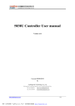
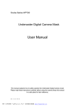
GuardTrak
User’s Manual
Securing your world
PDF created with FinePrint pdfFactory trial version www.pdffactory.com
PRECAUTIONS
Safety
Do not start up any defective devices, but contact your GuardTrak supplier for
advice. The station box is intended for operation in enclosed, dry spaces. Use
a level, dry surface for setting up.
Intended use
This device is exclusively intended for collecting and evaluating data. Any
other use will be regarded as unauthorized. Any damage to the device due to
unauthorized use, the manufacturer will not accept liability. Unauthorized
modification to the device will invalidate the manufacturer’s liability for any
damage thereby arising.
Maintenance & Repairs
The device may only be opened by trained staff. During maintenance work
and repairs, the device must be disconnected from the power supply. Check
the disconnected parts first to ensure they are not charged before continuing
the work. Working with the electrical components of the device may only be
carried out by a trained electrician or by people instructed and monitored by
an electrician and in conformity with the rules of electrical engineering.
PDF created with FinePrint pdfFactory trial version www.pdffactory.com
TABLE OF CONTENTS
1) INTRODUCTION………………………………………… 1
2) GENERAL SYSTEM DESCRIPTION……………….. 2~4
3) PREPERATION …………………………………………
5
4) SETTING THE DATE, TIME & SUMMER TIME …… 6~10
5) RECORDINGS …………………………………………… 11
6) EVALUATING THE RECORDED DATA ……………… 12
7) DELETING THE RECORDED DATA ………………….. 12
8) PRINTOUT SAMPLE ……………………………………. 13
9) RED & GREEN LED AND ACOUSTIC REFERENCE
FOR THE HAND-HELD DEVICE ………………………. 14
10) INSTALLING THE PAPER ROLL ..……………….. 15~16
11) CARE & MAINTENANCE ……………………………… 17
12) TECHNICAL DATA ……………………………………… 18
PDF created with FinePrint pdfFactory trial version www.pdffactory.com
1. INTRODUCTION
The GuardTrak system allows the recording of the guard rounds by electronic
collaboration of a wall station (checkpoint chips), hand-held device and station
box.
Features such as the time and date are preset at the factory. However, we
recommend reading this manual before you start using your GuardTrak
system.
Package Contents
-
GuardTrak data collecting hand-held device
-
Station box with integrated printer and battery charger
-
Mains power for station box: Adaptor INPUT AC100-240V
OUTPUT 6V …..3A
-
1 Master chip
-
3 Personnel tags
-
10 Checkpoint chips
-
1 Thermal paper roll
Optional & Additional Items
-
Personnel identification tags
-
Start & End cards
-
Incident cards
-
Checkpoint chips
-
Thermal paper roll (width 57mm)
1
PDF created with FinePrint pdfFactory trial version www.pdffactory.com
2. GENERAL SYSTEM DESCRIPTION
GuardTrak hand-held device
The GuardTrak hand-held device is used for recording the guard round data
during the guard patrol. It saves the recorded data in the hand-held device
until they are evaluated. The GuardTrak hand-held device is powered by an
integrated rechargeable lithium battery.
Battery operation of the GuardTrak hand-held device
The GuardTrak hand-held device can be deployed on the move because it is
equipped with a rechargeable lithium battery. In order to ensure operating
ability at all times, the battery must be charged i.e. any unused hand-held
device should be placed into the station box or the charging box. The charging
operation is indicated by the continually glowing red and green LED.
Loading status of the rechargeable battery
The battery loading status is electronically monitored. If the GuardTrak handheld device is not replaced into the station box for charging, the battery it will
lose its charge.
The GuardTrak hand-held device protects the integrated battery against quick
discharge with an in-built “shock sensor”. When the hand-held is placed down
e.g. on a table, after 10 seconds, it will switch to “Sleep mode”, indicated by
both LED lights being off. This will reduce the electricity consumption of the
electronic components. The hand-held device will immediately switch back to
“Standby mode” when moved or picked up. This will be indicated by a
continuous glowing red LED light.
*First time charging of the hand-held device requires minimum of 12
hours, thereafter, a minimum of 6 hours is required
2
PDF created with FinePrint pdfFactory trial version www.pdffactory.com
Checkpoints
The checkpoints chips are to be installed at the locations to be checked. They
are not sensitive to external influences such as impact, dirt or weather. The
individual checkpoint chips are numbered so that every checkpoint is assigned
a code. The checkpoint chips are labeled at the manufacturer. Up to 250
checkpoints are possible and are coded from number 1-250.
The checkpoint chips can be attached into place by either, a screw, a nail or
glue.
IMPORTANT:
Do not attached chips on to a metal surface.
Master chip
The master chip is used for setting the GuardTrak system.
It allows the program to be set and recorded data to be evaluated.
IMPORTANT:
* Keep the master chip at a secure place in order to prevent manipulation.
** Every time the Master chip has been scanned, you have 30 seconds to
start your inputs. If no inputs have been made after 30 seconds, you will
need to scan the Master chip again to proceed.
3
PDF created with FinePrint pdfFactory trial version www.pdffactory.com
Security Personnel Tag
The security personnel tag’s purpose is the identification of the guard person if
the hand-held device is used by different personnel. When the device is
handed over, the guard holds his security staff tag next to the hand-held
device. When this is done, all recordings in the intervening time are allocated
to this security staff no. The security staff tags are available with numbers from
1-250.
Start & End Cards
The optional “Start” & “End” cards are used when the management/controller
wants to track the exact time the guard starts and finish his or her rounds.
Before the guard starts the round, he or she will take the “Start” card and
make a recording onto the hand-held device. After completing the round, the
guard will make a second recording onto the hand-held device with the “End”
card.
Incident Cards
The optional incident cards, consisting of 10 cards, coded 1-10, will be carried
by the guard during his or her round.
Incident situation for each incident card is to be determined by the
user/controller. For example: code 1 card, unlocked door, code 2 card, broken
window, etc. When a representation for each card has been determined, a
sticker label can then be attached to the card.
4
PDF created with FinePrint pdfFactory trial version www.pdffactory.com
3. PREPARATION
Place the station box onto a level, dry surface near an electric power source.
Insert the connecting cable into the station box as in figure 1. Then insert the
plug to the main power supply.
Fig. 1
Insert the hand-held device into the station box. Once the hand-held device is
placed in the station box, it will immediately go into the “battery charging”
mode. The LCD screen on the station box will be blank. To display the current
time, press either the FUNC, + or Print buttons. To display the date, press
the – button. Both features will show for 15 seconds, after which, will revert
back to “battery charging” mode.
5
PDF created with FinePrint pdfFactory trial version www.pdffactory.com
4. SETTING THE DATE, TIME & SUMMER TME
Hold the master chip to the back of the GuardTrak hand-held device as in
figure 2, you will hear an acoustic signal “beep” and see a flash of green LED
light. Press the Func button for 3 seconds then, you will hear an acoustic
signal “beep” from the station box and the LCD screen will show 01. You may
now set the Date & Time.
Fig. 2
IMPORTANT
Every time the Master card has been scan, you have 30 seconds to start
your inputs. If no inputs have been made after 30 seconds, you will need
to scan the Master card again to proceed.
6
PDF created with FinePrint pdfFactory trial version www.pdffactory.com
Setting the Year
1) Press the Func button so that the LCD indicates 01.
2) Enter the current year with the + or – buttons.
3) Press the Print button to store programmed year.
Setting the Month
4) Press the Func button so that the LCD indicates 02.
5) Enter the current month with the + or – buttons.
6) Press the Print button to store the programmed month.
Setting the Day
7) Press the Func button so that the LCD indicates 03.
8) Enter the current day with the + or – buttons.
9) Press the Print button to store the programmed day.
7
PDF created with FinePrint pdfFactory trial version www.pdffactory.com
Setting the Hour
10) Press the Func button so that the LCD indicates 04
11) Enter the current hour with + or – buttons.
12) Press the Print button to store the programmed hour.
Setting the Minutes
13) Press the Func button so that the LCD indicates 05.
14) Enter the current minute with the + or – buttons.
15) Press the Print button to store the programmed minutes.
Setting the Time Display
16) Press the Func button so that the LCD indicates 06.
17) Enter the time display, 12 or 24 hours, with the + or – buttons.
18) Press the Print button to store the programmed time display.
8
PDF created with FinePrint pdfFactory trial version www.pdffactory.com
Setting the Summer Time
Starting Month
19) Press the Func button so that the LCD indicates 07
20) Enter the month when summer time starts with the + or – buttons.
21) Press the Print button to store the programmed starting month.
Starting Day
22) Press the Func button so that the LCD indicates 08.
23) Enter the day when summer time starts with the + or – buttons.
24) Press the Print button to store the programmed starting day.
Ending Month
25) Press the Func button so that the LCD indicates 09.
26) Enter the month when summer time ends with the + or – buttons.
27) Press the Print button to store the programmed ending month.
9
PDF created with FinePrint pdfFactory trial version www.pdffactory.com
Ending Day
28) Press the Func button so that the LCD indicates 10.
29) Enter the day that summer time ends with the + or – buttons.
30) Press the Print button to store the programmed ending day.
Summer Time On or Off
31) Press the Func button so that the LCD indicates 11.
32) Enter summer time, On or Off, with the + or – buttons.
33) Press the Print button to store the programmed summer time On or Off.
* When summer time is “On”, the wording SUMMER will be shown at the
bottom left hand corner on the LCD.
10
PDF created with FinePrint pdfFactory trial version www.pdffactory.com
5. RECORDINGS
A recording at a checkpoint is made by holding the GuardTrak hand-held
device in front of the checkpoints (see figure 3). A successful recording is
indicated by an acoustic signal (beep) and by a flash of green LED from the
hand-held device. When the recording is made, the current date, time and
checkpoint number will be saved in the hand-held device.
The hand-held device is not required to touch the checkpoint to make a
recording. By holding the hand-held device within 5cm in front of the
checkpoint will activated a recording.
Fig. 3
Incident card Recordings
When there is an incident at or near a checking point, i.e. broken window, unlocked door etc., first make a recording at the nearest checkpoint to the
incident with the hand-held device, then a second recording on the card which
indicated that particular event. One or more events can be recorded at any
particular checking point.
IMPORTANT:
Recordings can only be made from the back (Grey) side of the hand-held
device.
11
PDF created with FinePrint pdfFactory trial version www.pdffactory.com
6. EVALUATING THE RECORDED DATA
The evaluation of the recorded data is made via the station box. After the
completion of the guard round, the GuardTrak hand-held device is placed
back into the station box, which the data can be printed.
After you have placed the hand-held device into the station box, press any
button on the station box to connect the hand-held device to the station box,
you will hear an acoustic signal “beep” and the LCD on the station box will
show the current time. Hold the master chip behind the hand held device, you
will hear an acoustic signal “beep” and see a flash of green LED light. Press
the “PRINT” button for three seconds, the recorded data will be immediately
printed out. The printing process can be cancelled by taking the hand-held
device out of the station box.
This process can be repeated as often as required as long as the GuardTrak
hand-held device is located in the station box and no new recording at a
checkpoint has been made.
Warning: HOT – Do not touch the print thermal plate from the
thermal print head after a printout has just been made.
7. DELETING THE RECORDED DATA
The recorded data can be deleted by first printing out the stored data in the
hand-held device. Then make a recording with the hand-held device at the
nearest available checkpoint. As soon as you hear an acoustic signal “beep”
and by a flash of green LED from the hand-held device, the previously stored
data will be deleted.
12
PDF created with FinePrint pdfFactory trial version www.pdffactory.com
8. Printout Sample (not actual size)
*Print data for the patrol start & end time and the Incidents numbers are only
available when used with the optional Start & End cards and Incident cards.
13
PDF created with FinePrint pdfFactory trial version www.pdffactory.com
9. Red & Green LED and acoustic reference for the
hand-held device:
Battery charging:
When the hand-held device is first placed into the station box, both the Red &
Green LED will be on. After 1 minute of inactivity, the hand-held device will go
into sleep mode, and only the Green LED will be on.
When the battery is fully charged, both LED will be off.
Standby:
Red light on
Scanned:
Red LED will be on with a flash of Green LED and acoustic signal, (beep).
Battery low:
Just before the hand-held device goes into sleep mode, the Red LED will flash
five (5) times.
Downloading data:
Both the Red & Green LED flashes constantly until all the data had been
downloaded.
Memory capacity down to 200:
Just before the hand-held device goes into sleep mode, both the Red & Green
LED flashes five (5) times.
Sleep mode:
Both the Red & Green LED will be off.
14
PDF created with FinePrint pdfFactory trial version www.pdffactory.com
10. INSTALLING THE PAPER ROLL
1) Open the clear printer cover.
2) Remove the paper guide roller from the print mechanism: place two fingers
on the guide roller and roll the roller towards yourself. The guide roller will
dislodge from its’ holding position. See figure 4.
Fig. 4
3) Place a new paper roll into the holder.
4) Pull paper from the paper roll so that approx. 3 inches of the paper is
hanging over the print mechanism. See figure 5.
Fig. 5
15
PDF created with FinePrint pdfFactory trial version www.pdffactory.com
4) Place the guide roller on top of its’ holding position, with the paper
underneath. See figure 6.
Fig. 7
Place two fingers on top of the roller and push forwards until it is lodged back
into it holding position. At the same time, you will also hear a “click”.
5) Guide the paper through the tear-off slot in the printer cover and close the
cover.
IMPORTANT
The paper strip must not be pulled during the printing process.
16
PDF created with FinePrint pdfFactory trial version www.pdffactory.com
11. CARE & MAINTENANCE
The following information should be observed for continuous operating
availability and safety of the devices is maintained.
The GuardTrak hand-held device
The hand-held device should be occasionally cleaned using a damp cloth. No
abrasive or aggressive cleaners should be used to clean the housing. Ensure
that the holder sling is undamaged. Unused hand-held device should be
replaced back into the station box or charging box so that the battery is
charged and the hand-held device remain ready for use. If you experience any
functional faults, contact your GuardTrak supplier for assistance.
The Station box
Use a soft and dry cloth to clean the station box. If you find any components
are faulty, contact your GuardTrak supplier. For your own protection, you
should remove the power cables from the sockets. Do not use any faulty
cables connections.
Under no circumstances should you carry out any repairs to the
electronics of GuardTrak hand-held device and station box on your own.
If you find any functional faults you should contact your GuardTrak
supplier for assistance.
17
PDF created with FinePrint pdfFactory trial version www.pdffactory.com
12. TECHNICAL DATA
Technical data for the hand-held device
Power supply: Rechargeable lithium battery (3.7V)
Standby: max 30 days without charging
Charging time: at least 6 hours, when the battery is discharged
Battery lifetime: 2 years, during normal use
Booking memory: 3200 recordings
Dimensions: (HWD) 210 x 73 x 40 mm
Weight: approx. 240 gram
Temperature range: -10°C to + 55°C
Technical date for the station box
Power supply: Adaptor INPUT AC100-240V
OUTPUT 6V ….3A
Dimensions: (HWD) 240 x 139 x 90 mm
Weight: approx. 949 gram
Temperature range: Room temperature
Technical data for the checkpoint chips
Dimensions: diameter 30mm
Coded: from 1-250
18
PDF created with FinePrint pdfFactory trial version www.pdffactory.com