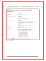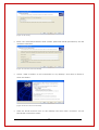
1
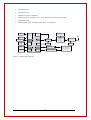
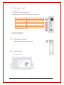
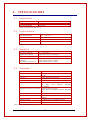
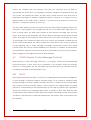
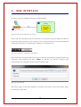
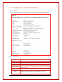
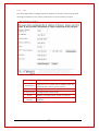
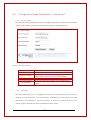
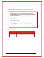
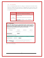
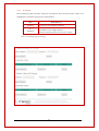
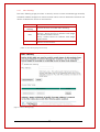
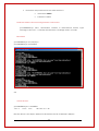
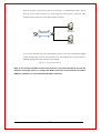
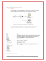
+
Unimax HSPA+ Ethernet Modem Router | MA-2025
+
Unimax 4G Ethernet Modem Router | MA-2025-4G
Unimax Ethernet Modem Router
MA-2025 | MA-2025-4G
User Manual
This manual is the sole and exclusive property of
Maxon Australia.
Not to be distributed or divulged without prior
written agreement.
4
TABLE OF CONTENTS
CONTACT INFORMATION ............................................................................ 8 RF EXPOSURE COMPLIANCE ....................................................................... 9 Caution ................................................................................................. 9 REVISION HISTORY ................................................................................. 11 UNIMAX+ USER MANUAL ......................................................................... 12 Disclaimers ......................................................................................... 12 1. INTRODUCTION ............................................................................ 13 1.1 Overview ................................................................................... 13 1.2 Features of 4G Model................................................................... 13 1.3 Features of 3G Model................................................................... 13 2. HARDWARE ................................................................................... 15 2.1 Front Panel ................................................................................ 15 2.2 Side Panel (Left) ......................................................................... 16 2.3 Side Panel (Right) ....................................................................... 16 2.4 Back Panel ................................................................................. 16 3. SPECIFICATIONS .......................................................................... 17 3.1 Mechanical ................................................................................. 17 3.2 Environmental ............................................................................ 17 3.3 Electrical.................................................................................... 17 3.4 Hardware ................................................................................... 17 4. PROTOCOLS & ENCRYPTIONS ........................................................ 18 4.1 PPP (Point-to-Point Protocol) ........................................................ 18 4.2 PPPoE (Point-to-Point Protocol over Ethernet) ................................. 18 4.3 DHCP (Dynamic Host Configuration Protocol) .................................. 19 4.4 NAT (Network Address Translation or Translator) ............................ 19 4.5 SNMP (Simple Network Management Protocol) ................................ 20 4.6 SNTP (Simple Network Time Protocol)............................................ 20 4.7 ICMP (Internet Control Message Protocol) ...................................... 21 4.8 NAT-T ....................................................................................... 21 4.9 IKE ........................................................................................... 22 4.9.1
3DES ..................................................................................... 22 4.9.2
AES ....................................................................................... 22 4.9.3
MD5 ..................................................................................... 22 4.9.4
SHA ...................................................................................... 22 4.10 ISAKMP ..................................................................................... 22 4.11 ESM .......................................................................................... 23 5
5. WEB INTERFACE............................................................................ 24 5.1 5.2 5.3 6. Configuration Page Descriptions .................................................... 25 5.1.1 Status .................................................................................. 25 5.1.2 LAN ..................................................................................... 27 5.1.2 WAN ................................................................................... 28 5.1.3 Maxconnect ......................................................................... 31 5.1.4 Password .............................................................................. 31 5.1.5 Log Out................................................................................ 32 Configuration Page Descriptions – Advanced ................................... 33 5.2.2 Dynamic DNS ........................................................................ 33 5.2.3 DoS Filters ............................................................................. 33 5.2.4 DMZ .................................................................................... 34 5.2.5 Port Forwarding ..................................................................... 35 5.2.6 IP Filtering ............................................................................. 36 5.2.7 MAC Filtering ......................................................................... 37 5.2.8 VPN ..................................................................................... 38 5.2.9 Digital I/O Control .................................................................. 38 5.2.10 Ping Tool .............................................................................. 40 5.2.11 SNMP ................................................................................... 41 5.2.12 Static Route .......................................................................... 42 Configuration Page Descriptions – Administrator ............................. 42 5.3.3 AT ....................................................................................... 42 5.3.4 Backup (Save/Reload) ............................................................ 43 5.3.5 Time Zone ............................................................................. 45 5.3.6 System ................................................................................. 46 5.3.7 Upgrade Firmware ................................................................. 47 5.3.8 Save & Reboot ...................................................................... 48 OPERATION ................................................................................... 49 6.1 Modem Router Mode ................................................................... 49 6.1.1 6.2 Setting Host PC’s Network Environment ....................................... 49 Bridge Mode ............................................................................... 51 APPENDIX ................................................................................................ 56 Digital Input/Output ................................................................................ 56 H/W Specifications............................................................................. 56 Electrical Specifications ...................................................................... 56 Diagram .......................................................................................... 56 Upgrade Firmware .............................................. Error! Bookmark not defined. Factory Default Function .......................................................................... 57 6
Hard Reboot .................................................................................... 57 Soft Reboot ...................................................................................... 57 SMS Commands ........................................................................................ 57 Commands ...................................................................................... 57 Requirements: .................................................................................... 59 WAN Connection – Signal Level ................................................................ 61 Setting SNMP Agent ................................................................................. 61 Environment ..................................................................................... 61 Unimax+ Configuration ..................................................................... 61 PowerSNMP Free Manager Configuration ............................................... 62 Setting Unimax+ as a VPN Gateway or VPN Client ................................... 64 VPN Gateway .................................................................................. 64 VPN Client (L2TP over IPSec) ................................................................ 65 VPN Client (IPSec) ............................................................................. 68 VPN Client (PPTP)............................................................................... 69 Advanced Settings ................................................................................... 69 Connecting to a HUB ......................................................................... 69 Port Forwarding ................................................................................. 69 Setting DMZ Host ............................................................................. 72 Troubleshooting ....................................................................................... 73 Hardware Issues ................................................................................ 73 Software Issues .................................................................................. 73 7
CONTACT INFORMATION
In keeping with Maxon's dedicated customer support policy, we encourage you to
contact us.
TECHNICAL:
Hours of Operation: Monday to Friday 8.30am to 5.30pm*
Telephone:
+61 2 8707 3000
Facsimile:
+61 2 8707 3001
Email:
[email protected]
* Public holidays excluded
SALES:
Hours of Operation: Monday to Friday 8.30am to 5.30pm*
Telephone:
+61 2 8707 3000
Facsimile: +
61 2 8707 3001
Email:
[email protected]
WEBSITE:
www.maxon.com.au
* Public holidays excluded
ADDRESS:
Maxon Australia Pty Ltd
36a Gibson Avenue, Padstow
Sydney, NSW, Australia 2211
POSTAL ADDRESS
Maxon Australia Pty Ltd
Po Box 1, Revesby North,
Sydney, NSW Australia 2212
8
RF EXPOSURE COMPLIANCE
The use of this device in any other type of host configuration may not comply with the
RF exposure requirements and should be avoided. During operation, a 20 cm
separation distance should be maintained between the antenna, whether extended or
retracted, and the user’s/bystander’s body (excluding hands, wrists, feet, and ankles) to
ensure RF exposure compliance.
Caution
Change or modification without the express consent of Maxon Australia Pty Ltd voids
the user’s authority to use the equipment. These limits are designed to provide
reasonable protection against harmful interference in an appropriate installation. The
modem is a transmitting device with similar output power to a mobile phone. This
equipment generates, uses, and can radiate radio frequency energy and, if not used in
accordance with instructions, can cause harmful radiation to radio communication.
The modem is approved for use with the antenna: ANT-FME. Unauthorized antennas,
modifications, or attachments could impair call quality, damage the device, or result in
violation of RF exposure regulations.
In addition, there is no guarantee that interference will not occur in a particular
installation. If the equipment does cause harmful interference in radio and television
reception, which can be determined by turning the equipment on and off, the user is
encouraged to try to correct the interference by one or more of the following
measures:
!
Re-orient or relocate the receiving radio or TV antenna
!
Increase the separation distance between the equipment and the receiver
!
Contact Maxon Australia Technical Support for assistance.
Notes
The user is cautioned that changes or modifications not expressly approved by Maxon
Australia could void the warranty.
9
Potentially Unsafe Areas
Posted Facilities: Turn off this device in any facility or area when posted notices require
you to do so.
Blasting Areas: Turn off your device where blasting is in progress. Observe restrictions
and follow any regulations or rules.
Potentially Explosive Atmospheres: Turn off your device when you are in any area with a
potentially explosive atmosphere. Obey all signs and instructions. Sparks in such areas
could cause an explosion or fire, resulting in bodily injury or death.
Areas with a potentially explosive atmosphere are often but not always clearly marked.
They include:
•
Fuelling areas such as gas or petrol stations
•
Below deck on boats
•
Transfer or storage facilities for fuel or chemicals
•
Vehicles using liquified petroleum gas, such as propane or butane
•
Areas when the air contains chemicals or particles such as grain, dust or metal
powders
•
Avoid using the modem in areas that emit electromagnetic waves or enclosed
metallic structures, e.g. lifts
•
Any other area where you would normally be advised to turn off your engine
10
REVISION HISTORY
Product
Model
Document Type
Current Version Number
Status of the Document
Revision Date
Total Number of Pages
UNIMAX+ Industrial Ethernet Router
MA-2025, MA-2025-4G
PDF
1.5
Public Release
July 2014
72
Revision History
Date
April 2014
May 2014
July 2014
Level
1.0
1.1
1.2
1.3
1.4
1.5
History
Internal Release Version
Public Release
Maxon Australia, LEDs operation
Internal Release with 4G
Added Invalid PPP password characters
4G Release
11
UNIMAX+ USER MANUAL
All data and information contained in or disclosed by this document are confidential
and proprietary information of Maxon Australia, and all rights therein are expressly
reserved. By accepting this material, the recipient agrees that this material and the
information contained therein are held in confidence and in trust and will not be used,
copied, reproduced in whole or in part, nor its contents revealed in any manner to
others without the express written permission of Maxon Australia. This information
provided in this document is provided on an “as is” basis.
In no event will Maxon Australia be liable for any damages arising directly or indirectly
from any use of information contained in this document. Information in this document is
preliminary and subjected to change without any notice.
Disclaimers
Life support – This product is not designed for use in life support appliances or systems
where malfunction of these products can reasonably be expected to result in personal
injury.
Maxon Australia customers using or selling these products for use in such applications
do so at their own risk and agree to fully indemnify Maxon Australia for any damages
resulting from such application.
Right to make change - Maxon Australia reserves the right to make changes, without
notice, in the products, including circuits and software, described or contained herein
in order to improve design and/or performance.
12
1.
INTRODUCTION
1.1
Overview
The Unimax+ Ethernet Router performs data communication functions between wiredLAN (Local Area Network) and wireless WAN (Wide Area Network) using LTE cellular
station wirelessly (Unimax+ 4G) and HSPA cellular stations wirelessly (Unimax+ 3G). The
Unimax+ has wide input voltage range from 9~30 [VDC] which provides compatibility
for platforms utilizing various industrial applications.
1.2
MA-2025-4G Feature set
!
LTE Wireless Module MC7304 PCI (100 Mbps downlink, 50 Mbps uplink)
!
Frequency Bands – LTE 2100/1800/2600/900/ 800 MHz
!
Carrier Support in Australia- Telstra (4G 1800 MHz/3G 850MHz and GSM 900/1800
MHz, Optus (4G 1800 MHz/ 3G 900/2100 MHz and GSM 900/1800MHz), Vodafone
(4G 1800MHz, 3G 2100Mz and GSM 900/1800 MHz)
!
10/100Mbps Ethernet Port, Supports 10/100MHz Auto-Sensing
!
32-bit RISC Network System on Chip
!
System clock 175MHz (CPU) and 88MHz (BUS)
!
3-Status LEDs indicator for device status
!
External Antenna (FME Male)
!
Periodic Reset
!
Diagnostic Port
!
Digital Inputs (Support 5V)
!
Digital Outputs (Support 3.3V)
!
L2TP/IPsec VPN
!
Wide Range input Voltage range from 9 to 30[VDC]
1.3
MA-2025 Feature set
!
HSPA Wireless Module MC8705 PCI (21.1 Mbps downlink, 5.76 Mbps uplink)
!
Frequency Bands - WCDMA 850/900/1900/2100 MHz
!
10/100Mbps Ethernet Port, Supports 10/100MHz Auto-Sensing
!
32-bit RISC Network System on Chip
!
System clock 175MHz (CPU) and 88MHz (BUS)
!
3-Status LEDs indicator for device status
!
External Antenna (FME Male)
13
!
Periodic Reset
!
Diagnostic Port
!
Digital Inputs (5V tolerable)
!
Digital Outputs (Supports up to 24V, 30mA with external I/O Board)
!
L2TP/IPsec VPN
!
Wide Range input Voltage range from 9 to 30[VDC]
NOR
Flash
(8MB)
SIM
Socket
USB 2.0
Memory
BUS
SDRAM
(32MB)
Push S/W
(Factory reset)
Ethernet
Port
&
Debug
Status
LED
(2Ea)
JTAG
Cable
GPIO
USB2.0
Switcher
UART
Debug
Port
(14 Pin)
GPIO
MODEM
CPU
WAN
GPIO
EJTAG
Digital Input
Module
(Support 5V)
Interrupt
Digital Output Module
(Changed Ext signal?)
GPIO
[Figure 1: System Block diagram]
Mini PCI
Express
&
70pin
Connector
14
Status
LED
(1Ea)
Ext Connector
(Molex 5268)
2.
2.1
HARDWARE
Front Panel
[Figure 1:MA-2025] [Figure 1:MA-2025]
LED
Wireless Signal
[Figure 2:MA-2025-4G]
DISPLAY
DESCRIPTION
5 seconds ON, 0.2 seconds OFF
Searching for a service
0.4 seconds ON, 0.1 seconds OFF
When connected
When connected and transferring
data
Indicates connection mode with no
data communication
Indicates connection mode with
data communication
Indicates Unimax+ is not connected
to Internet
Indicates main power is ON
Indicates main power is OFF
0.4 seconds ON, 0.1 seconds OFF
Solid ON
Send/Receive
Data
500ms ON and 500ms OFF
OFF
POWER
ON
OFF
[Table 1: LED Display]
15
2.2
Side Panel (Left)
1. Ethernet Port
2. Diagnostic Port (for debugging)
3. Digital I/O (Input: max 5VDC, Output: max 3.3VDC)
PIN NUMBER
1 (VDD)
2 (D/I 1)
DESCRIPTION
3.3V out
Digital input (max 5VDC)
3 (D/I 2)
4 (D/O 1)
5 (D/O 2)
6 (GND)
Digital input (max 5VDC)
Digital output (max 3.3VDC)
Digital output (max 3.3VDC)
GND
[Table 2: Digital I/O PIN Number]
4. Reset (Factory Reset)
5. Power (9 – 30VDC)
2.3
Side Panel (Right)
3G/4G FME Male Antenna Connector
2.4
Back Panel
SIM Connector
16
3.
3.1
SPECIFICATIONS
Mechanical
Dimension
Weight
Housing Material
75.7 x 122.0 x 20.6 mm (with side bracket)
128g Approx.
Aluminum
[Table 3: Mechanical Specifications]
3.2
Environmental
Operating Temp
- 10 ~ + 65 [°C]
Extreme Operating Temp
- 20 ~ + 70 [°C]
Storage Temp
- 40 ~ + 90 [°C]
Humidity
5% ~ 95%
[Table 4: Environmental Specifications]
3.3
Electrical
DC Input Voltage
+ 9 ~ +30 [VDC]
Maximum Current
Under 1000 [mA] @ 12[VDC]
Internal Voltage
Operating Current
Standby
PKT Data Connection
+1.8, +2.5 +3.3, + 3.8, + 5 [VDC]
Under 150 [mA] @ 12 [VDC]
Under 180 [mA] @ 12 [VDC]
[Table 5: Electrical Specifications]
3.4
Hardware
ITEM
Product
DESCRIPTION
UNIMAX+ (3G & 4G) Industrial Ethernet
Router
User MCU
32-bit Network Processor
Program Memory
8M Bytes (Flash)
Data Memory
32M Bytes (SDRAM)
Wireless Interface 4G model LTE Module
LTE
Mini
PCI
Express
Module
MC7304PCI
Wireless Interface 3G model HSPA WCDMA Module
HSPA Mini PCI Express Module MC8705
PCI
15-Pin Diagnostic Port
1 Test Port
Ethernet
1 Port 10/100Mbps Ethernet (only Full
Duplex)
Digital I/O Port
2 Digital Inputs, 2 Digital Outputs
Display
3 Status LED’s
R-UIM
Support
[Table 6: Hardware Specifications]
17
4.
4.1
PROTOCOLS & ENCRYPTIONS
PPP (Point-to-Point Protocol)
PPP (Point-to-Point Protocol) is a protocol for communication between two computers
using a serial interface, typically a personal computer connected by phone line to a
server. For example, your Internet service provider may provide you with a PPP
connection so that the provider's server can respond to your requests, pass them on to
the Internet, and forward the requested Internet responses back to you. PPP uses the
Internet protocol (IP) and is designed to handle others. It is sometimes considered a
member of the TCP/IP suite of protocols. Relative to the Open Systems Interconnection
(OSI) reference model, PPP provides layer 2 (data-link layer) services. Essentially, it
packages your computer's TCP/IP packets and forwards them to the server where they
can actually be put on the Internet.
PPP is a full-duplex protocol that can be used on various physical media, including
twisted pair or fiber optic lines or satellite transmission. It uses a variation of High Speed
Data Link Control (HDLC) for packet encapsulation.
4.2
PPPoE (Point-to-Point Protocol over Ethernet)
PPPoE (Point-to-Point Protocol over Ethernet) is a specification for connecting multiple
computer users on an Ethernet local area network to a remote site via a modem. PPPoE
can be used to have an office or building-full of users share a common Digital
Subscriber Line (DSL), cable modem, or wireless connection to the Internet. PPPoE
combines the Point-to-Point Protocol (PPP), commonly used in dialup connections, with
the Ethernet protocol, which supports multiple users in a local area network. The PPP
protocol information is encapsulated within an Ethernet frame.
PPPoE has the advantage that neither the telephone company nor the Internet service
provider (ISP) needs to provide any special support. Unlike dialup connections, DSL and
cable modem connections are "always on." Since a number of different users are
sharing the same physical connection to the remote service provider, a way is needed
to keep track of which user traffic should go to and which user should be billed. PPPoE
provides for each user-remote site session to learn each other's network addresses
(during an initial exchange called "discovery"). Once a session is established between
an individual user and the remote site (for example, an Internet service provider), the
session can be monitored for billing purposes.
18
4.3
DHCP (Dynamic Host Configuration Protocol)
DHCP (Dynamic Host Configuration Protocol) is a communication protocol that lets
network administrators centrally manage and automate the assignment of Internet
Protocol (IP) addresses in an organization's network. Using the Internet Protocol, each
machine that connects to the Internet needs a unique IP address, which is assigned
when an Internet connection is created for a specific computer. Without DHCP, the IP
address must be entered manually at each computer in an organization and a new IP
address must be entered each time a computer moves to a new location on the
network. DHCP lets a network administrator supervise and distribute IP addresses from a
central point and automatically sends a new IP address when a computer is plugged
into a different place in the network.
DHCP uses the concept of a "lease" or amount of time that a given IP address will be
valid for a computer. The lease time can vary depending on how long a user requires
the Internet connection at a particular location. It's especially useful in education and
other environments where users change frequently. Using very short leases, DHCP can
dynamically reconfigure networks in which there are more computers than there are
available IP addresses. The protocol also supports static addresses for computers that
need a permanent IP address, such as Web servers.
4.4
NAT (Network Address Translation or Translator)
NAT (Network Address Translation or Network Address Translator) is the translation of an
Internet Protocol address (IP address) used within one network to a different IP address
known within another network. One network is designated as the inside network and
the other as the outside. Typically, a company maps its local inside network addresses
to one or more global outside IP addresses and un-maps the global IP addresses on
incoming packets back into local IP addresses. This helps ensure security since each
outgoing or incoming request must go through a translation process that also offers the
opportunity to qualify or authenticate the request or match it to a previous request. NAT
also conserves on the number of global IP addresses that a company needs and it lets
the company use a single IP address in its communication with the world.
NAT is included as part of a router and is often part of a corporate firewall. Network
administrators create a NAT table that does the global-to-local and local-to-global IP
address mapping. NAT can also be used in conjunction with policy routing. NAT can be
statically defined or it can be set up to dynamically translate from and to a pool of IP
addresses. NAT lets an administrator create tables that map:
19
!
A local IP address to one global IP address statically
!
A local IP address to any of a rotating pool of global IP addresses that a company
may have
!
A local IP address plus a particular TCP port to a global IP address or one in a pool
of them
!
A global IP address to any of a pool of local IP addresses on a round-robin basis
NAT is described in general terms in RFC 1631, which discusses NAT's relationship to
Classless Inter-domain Routing (CIDR) as a way to reduce the IP address depletion
problem. NAT reduces the need for a large amount of publicly known IP addresses by
creating a separation between publicly known and privately known IP addresses. CIDR
aggregates publicly known IP addresses into blocks so that fewer IP addresses are
wasted.
4.5
SNMP (Simple Network Management Protocol)
Simple Network Management Protocol (SNMP) is the protocol governing network
management and the monitoring of network devices and their functions. It is not
necessarily limited to TCP/IP networks.
4.6
SNTP (Simple Network Time Protocol)
Simple Network Time Protocol (SNTP) is a protocol that is used to synchronize computer
clock times in a network of computers. In common with similar protocols, SNTP uses
Coordinated Universal Time (UTC) to synchronize computer clock times to a millisecond,
and sometimes to a fraction of a millisecond.
Accurate time across a network is important for many reasons; even small fractions of a
second can cause problems. For example, distributed procedures depend on
coordinated times to ensure that proper sequences are followed. Security mechanisms
depend on coordinated times across the network. File system updates carried out by a
number of computers also depend on synchronized clock times. Air traffic control
systems provide a graphic illustration of the need for coordinated times, since flight
paths require very precise timing (imagine the situation if air traffic controller computer
clock times were not synchronized).
UTC time is obtained using several different methods, including radio and satellite
systems. Specialised receivers are available for high-level services such as the Global
Positioning System (GPS). However, it is not practical or cost-effective to equip every
computer with one of these receivers. Instead, computers designated as primary time
20
servers are outfitted with the receivers and they use protocols such as SNTP to
synchronize the clock times of networked computers. Degrees of separation from the
UTC source are defined as strata. A radio clock (which receives true time from a
dedicated transmitter or satellite navigation system) is stratum-0; a computer that is
directly linked to the radio clock is stratum-1; a computer that receives its time from
astratum-1 computer is stratum-2, and so on.
The term SNTP applies to both the protocol and the client/server programs that run on
computers. The programs are compiled by the user as an SNTP client, SNTP server, or
both. In basic terms, the SNTP client initiates a time request exchange with the time
server. As a result of this exchange, the client is able to calculate the link delay, its local
offset, and adjust its local clock to match the clock at the server's computer. As a rule,
six exchanges over a period of about five to 10 minutes are required to initially set the
clock. Once synchronized, the client updates the clock about once every 10 minutes,
usually requiring only a single message exchange. Redundant servers and varied
network paths are used to ensure reliability and accuracy. In addition to client/server
synchronization, SNTP also supports broadcast synchronization of peer computer clocks.
SNTP is designed to be highly fault-tolerant and scalable.
4.7
ICMP (Internet Control Message Protocol)
ICMP (Internet Control Message Protocol) is a message control and error-reporting
protocol between a host server and a gateway to the Internet. ICMP uses Internet
Protocol - IP data-grams, but the messages are processed by the IP software and are
not directly apparent to the application user.
4.8
NAT-T
NAT-T (NAT Traversal in the IKE) is a method of enabling IPSec-protected IP datagram’s
to pass through a Network address translator (NAT). An IP packet is modified while
passing through a network address translator device in a manner that is incompatible
with Internet Protocol Security (IPSec). NAT-T protects the original IPSec encoded
packet by encapsulating it with another layer of UDP and IP headers. The negotiation
during the Internet key exchange (IKE) phase is defined in RFC 3947 and the UDP
encapsulation itself is defined in RFC 3948. Most major networking vendors support NATT for IKEv1 in their devices. In Microsoft Windows XP with Service Pack 2 the feature can
be enabled.
21
4.9
IKE
Internet Key Exchange (IKE or IKEv2) is the protocol used to set up a security association
(SA) in the IPSec protocol suite. IKE uses a Diffie-Hellman key exchange to set up a
shared session secret, from which cryptographic keys are derived. Public key
techniques or, alternatively, a pre-shared key, are used to mutually authenticate the
communicating parties.
4.9.1
3DES
The earliest standard that defines the algorithm (ANS X9.52, published in 1998)
describes it as the "Triple Data Encryption Algorithm (TDEA)" — i.e. three operations
of the Data Encryption Algorithm specified in ANSI X3.92 — and does not use the
terms "Triple DES" or "DES".
4.9.2
AES
The Advanced Encryption Standard (AES) is an encryption standard adopted by
the U.S. government. The standard comprises three block ciphers, AES-128, AES-192
and AES-256, adopted from a larger collection originally published as Rijndael. Each
AES cipher has a 128-bit block size, with key sizes of 128, 192 and 256 bits,
respectively. The AES ciphers have been analyzed extensively and are now used
worldwide.
4.9.3
MD5
MD5 (Message-Digest algorithm 5) is a widely used cryptographic hash function
with a 128-bit hash value. As an Internet standard (RFC 1321), MD5 has been
employed in a wide variety of security applications, and is also commonly used to
check the integrity of files.
4.9.4
SHA
SHA stands for Secure Hash Algorithm. The three SHA algorithms are structured
differently and are distinguished as SHA-0, SHA-1, and SHA-2. The SHA-2 family uses
an identical algorithm with a variable digest size which is distinguished as SHA-224,
SHA-256, SHA-384, and SHA-512.
4.10
ISAKMP
ISAKMP defines the procedures for authenticating a communicating peer, creation and
management of Security Associations, key generation techniques, and threat
mitigation (e.g. denial of service and replay attacks). ISAKMP typically utilizes IKE for key
exchange, although other methods can be implemented.
22
4.11
ESM
Encapsulating Security Payload (ESP) is a member of the IPSec protocol suite. In IPSec, it
provides origin authenticity, integrity, and confidentiality protection of packets. ESP also
supports encryption-only and authentication-only configurations, but using encryption
without authentication is strongly discouraged because it is insecure. Unlike
Authentication Header (AH), ESP does not protect the IP packet header. However, in
Tunnel Mode, where the entire original IP packet is encapsulated with a new packet
header added, ESP protection is afforded to the whole inner IP packet (including the
inner header) while the outer header remains unprotected. ESP operates directly on
top of IP, using IP protocol number 50.
23
5.
WEB INTERFACE
Unimax+ can be configured through its web interface.
[Figure 2: Web-based configuration of Unimax+]
Power ON the Unimax+ Router and connect to a computer using an Ethernet cable. To
launch the web interface of the Unimax+, open a web browser such as Internet Explorer
for Windows and type the following IP address in the address bar:
[Figure 3: Web-based configuration page address]
Enter username and password in the pop-up window that prompts for login details. The
Username and password are both ‘admin’ by default. The default username and
password can be changed on the Password Setup Page.
[Figure 4: Log-in window]
The Home page of the web interface of Unimax+ will come up with connection status
and device information.
24
5.1 Configuration Page Descriptions
5.1.1
Status
Status page displays the current status of LAN, WAN and Network Information.
[Figure 5: Status Page]
ITEM
Up Time
Operation time after power up
System Time
System time acquired from modem
F/W Version
Current firmware version of Unimax+ Router
Current Firmware version of the cellular module inside
Unimax+ Router
Module Version
WAN
(Current mode)
WAN IP
DESCRIPTION
Current operation mode i.e. Modem Router or Bridge
IP address assigned by ISP such as Telstra or Optus
25
Netmask
Network
Registration
Network
PIN Status
Network Band
Signal Level
Send/Receive
Packets
LAN
IP
Netmask
MAC
Send/Receive
Packets
Subnet Mask assigned by ISP such as Telstra or Optus
Status of the module including registration
Network status of Unimax+ Router
Status of PIN request (enable/disable)
Cellular Band Frequency Information of 3G or 4G network
Status of current signal strength(dBm)
Status of Incoming and Outgoing WAN data packets. This is
for information purpose only and should not be used for
billing purposes.
Unimax+ IP address
Subnet Mask assigned by Unimax+ for LAN
MAC address of Unimax+ LAN adaptor
Status of Incoming and Outgoing LAN data packets
[Table 6: Status Page Information]
26
5.1.2
LAN
The LAN page allows configuring the IP address of Unimax+, DHCP range and
viewing information of the clients connected on the Unimax+ LAN port.
[Figure 6: LAN Page]
ITEM
Unimax+
Gateway IP
IP Address
Subnet Mask
DHCP
DHCP Client
Range
DESCRIPTION
Unimax+ can be configured with a Static IP or
can be set to obtain an IP address from an
external DHCP Server (Client Mode)
Configure Unimax+ IP address
Configure the subnet mask
Enable or Disable DHCP server of Unimax+
Assign IP address range for DHCP Server of
Unimax+
[Table 8: LAN Page Information]
27
5.1.2
WAN
The WAN page allows configuring network authentication information, connection
retrial and Scheduler timers.
[Figure 7: WAN Page]
28
ITEM
Mode
Profile
APN Name
Dialup
Data Limitation
User Name
Password
MTU
Authentication
PPP Echo
Check
Auto PIN
Enable/Disable
PIN
Band
Selection
Ethernet Link
Back Off
DESCRIPTION
Modem Router Mode
Bridge Mode
Select a predefined profile or create one using
the custom option
Select APN Name provided by the ISP
Telephone number to dial
Data can limited to certain value. Once it is
reached the WAN connection will stop
Username provided by the ISP
Password provided by the ISP
Maximum Transmission Unit of Unimax+
Select Authentication scheme used by the ISP
LCP echo interval time can be set by the user.
This option checks the status of the PPP
connection.
Unimax+ Router will automatically enter the PIN
code if the PIN request on the USIM card is
enabled. Please enter correct PIN code as
incorrect PIN code will lock the SIM card.
This feature will allow users to disable or enable
SIM PIN from the Unimax+ Router
A particular band can be selected or left on
Auto using this option
This setting controls the WAN connection.
Disabling this will prevent Unimax+ establishing a
WAN connection if no client is connected on
the LAN. Disconnecting client from LAN will also
force Unimax+ to disconnect WAN connection
with this setting disabled
Unimax+ will start a back off algorithm on
power up as set by these times instead of
constantly retrying PPP connection. Unimax+ will
reset if PPP connection is not successful after 2nd
retrial timer has expired and start again.
1st Retrial when wireless network gets
disconnected.
Interval: Retrial interval time (Second)
During time: Continuing time (Minute)
2nd Retrial after 1st retrial is unsuccessful
PING Check
Periodic Reset
Scheduler
Interval: Retrial interval time (Minute)
During time: Continuing time (Hour)
Ping Check settings allow pinging 2 designated
servers
at
set
intervals.
Unimax+ will disconnect WAN connection and
performs a power reset if the ping fail count
expires for both servers
Power Reset Unimax+ daily
Set from 1 to 24 hours
Unimax+ establishes WAN connection (Router
Mode) between the times specified above.
Disabling this function allows Unimax+ to be
online at all times
29
[Table 9: WAN Page Information]
Invalid PPP password characters list:
“(double quotation mark)
‘(quotation mark)
?(question mark)
)(bracket)
@(at sign)
;(semi colon)
|(pipe sign)
I(upper case I)
30
5.1.3
maXconnect
The maXconnect Remote Management portal allows you to manage, control and
monitor this device on the maXconnect portal. The settings below are used to
configure the Unimax+ to communicate with the maXconnect Remote
Management portal. The maxconnect FTP server is need to perform FOTA via the
portal. maXconnect is compatible with firmware later than 5.4.15.
5.1.4
Password
The Password page allows changing the authentication information required to
access the Unimax+ web page. If new authentication details are applied, you will
be prompted to re-enter those details as a confirmation.
ITEM
User name
Current
Password
New Password
Confirm
Password
DESCRIPTION
Input new login user name
Input the current login password
Input new login password
Retype the new password
[Table 10: Password Page Information]
31
[Figure 8: Password Page]
5.1.5
Log Out
Log Out page provides a user with an option to close the web interface window.
[Figure 9: Log out Page]
32
5.2
Configuration Page Descriptions – Advanced
5.2.2
Dynamic DNS
The Dynamic DNS page allows users to configure Username, Password and Domain
name to be used by Unimax+ when authenticating on the DDNS server.
[Figure 10: Dynamic DNS Page]
ITEM
Enable DDNS
Service Provider
Domain Name
User Name/Email
Password/Key
DESCRIPTION
Check box to enable DDNS
Link of the DDNS service web page
(Server site is http://dyndns.com) by default
Set DDNS host name or Alias from DDNS server
Input User Name for logging onto a DDNS server
Input Password for logging onto a DDNS
server
[Table 11: DDNS Page Information]
5.2.3
DoS Filters
This page allows the user to congfigure the Unimax to be blocked from DoS attack.
Using the DoS filter features, TCP SYN packets, TCP/UDP New Connections and ICMP
requested can be filtered to avoid DoS attacks. In order to use this feature, the user
should upgrade their device with a firmware later then 5.4.23
33
5.2.4
DMZ
The DMZ page allows one IP address in a Demilitarized Zone which is exposed to the
internet without sacrificing unauthorized access to the local private network.
[Figure 11: DMZ Page]
ITEM
Enable DMZ
DMZ Host IP
Address
DESCRIPTION
Check box to enable DMZ
IP Address of the target device. If DMZ is set, all
traffic addressed to Unimax+ WAN IP is passed
to the host with this IP address only. Web
interface of the Unimax+ will not be accessible.
[Table 12: DMZ Page Information]
34
5.2.5
Port Forwarding
The Port forwarding page allows for setting up a firewall that will allow remote
access for specific ports and protocols to designated hosts. When remote users
send requests for accessing the local server, Unimax+ can forward those requests to
the appropriate server(s).
ITEM
Enable Port
Forwarding
DESCRIPTION
Check box to enable Port Forwarding
Redirect IP Address: IP address of the target
device on LAN
Port
Forwarding
Protocol: Select protocol TCP, UDP or both
Port Range: Range of port addresses for
redirection
[Table 13: Port Forwarding Page Information]
[Figure 12: Port Forwarding Page]
35
5.2.6
IP Filtering
The IP filtering page provides simply a mechanism that decides which types of IP
datagram’s should be processed or discarded.
ITEM
Enable IP
Filtering
IP
Filtering
DESCRIPTION
Check box to enable IP Filtering
IP Address
IP address of the target device
Protocol: Select protocol TCP, UDP or both
[Table 14: IP Filtering Page Information]
[Figure 13: IP Filtering Page]
36
5.2.7
MAC Filtering
The MAC Filtering page provides a security access control methodology whereby
the 48-bit address assigned to each network card is used to determine whether the
device is allowed or access to the internet.
ITEM
Enable MAC
filtering
Rule
MAC Address
DESCRIPTION
Check the box to enable MAC Filtering
Select Access or Deny.
Access - Allows access to Unimax+ web page
but denies internet access.
Deny – Denies access to Unimax+ web page
and internet.
Input MAC address to determine deny or
access to the internet.
[Table 15: MAC Filtering Page Information]
[Figure 14: MAC Filtering Page]
37
5.2.8
VPN
The VPN page allows configuring VPN Server/Client mode in the Unimax+. The
Unimax+ VPN supports only L2TP OVER IPSec protocol.
[Figure 15: VPN Page]
ITEM
Mode
DESCRIPTION
VPN Gateway (L2TP/IPSec):
Unimax+ acts as a VPN Server
VPN Client (L2TP/IPSec
VPN Client (IPSec)
VPN Client (PPTP):
Unimax+ connects to a remote VPN Server
[Table 16: VPN Page Information]
5.2.9
Digital I/O Control
The Digital I/O page allows the user to configure the messages to be sent via SMS
when an Input changes state and which messages will be accepted to make an
output change state.
38
[Figure 16: Digital I/O Control Page]
39
ITEM
Activate
Trigger Time
Reporting
Number
Message
INPUT
Message
OUTPUT
DESCRIPTION
To enable or disable this function
Trigger time when input status changes from
low to high or from high to low
Enter mobile numbers for sending SMS in
international format. e.g. (+614….) If no
numbers are changed here the outputs will
not change on SMS
This message will be sent via SMS to
designated phone numbers when an input
changes state
This is the message that will switch the outputs
on when received only from the designated
phone numbers. The Unimax+ will ignore the
message received from different phone
numbers than the designated on this page.
[Table 17: Digital I/O Control Page Information]
5.2.10 Ping Tool
The Ping Tool page is used to send ICMP requests to a particular IP Address/Host
Name.
ITEM
IP Address
/Host Name
DESCRIPTION
Input destination IP address or host name to
be pinged.
[Table 18: Ping Tool Page Information]
[Figure 17: Ping Tool Page]
40
5.2.11 SNMP
The SNMP page is used to configure SNMP agent. If this option is enabled then a
remote SNMP manager can connect to the SNMP agent and acquires network
information. The Unimax+ supports SNMPV2. Please contact Maxon for the most up
to date MIB.
ITEM
Activate
System Name
System
Contact
Write
Community
Name
Read
Community
Name
1st Trap Server
IP
nd
2 Trap Server
IP
3rd Trap Server
IP
DESCRIPTION
To enable or disable the function
SNMP agents system name
SNMP agents contact email address
Public: Write Community string
Private: Write Community string disabled
Public: Read Community string
Private: Read Community string disabled
IP address of the 1st trap server. Unimax+ will
report trap message to this IP address.
IP address of the 2nd trap server. Unimax+ will
report trap message to this IP address.
IP address of the 3rd trap server. Unimax+ will
report trap message to this IP address.
[Table 19: SNMP Page Information]
[Figure 18: SNMP Page]
41
5.2.12 Static Route
This feature allows the user to configure static routes in the modem via the
LAN, WAN and VPN interfaces. Using this feature the user can communicate
in both directions once a VPN is established.
5.3
Configuration Page Descriptions – Administrator
5.3.3
AT
The AT page allows for sending commands to the Unimax+ module.
[Figure 21: AT Commands Page]
42
ITEM
AT Command
DESCRIPTION
Input AT command and click Send
[Table 22: AT Commands Page Information]
5.3.4
Backup (Save/Reload)
The Backup page allows users to save the current settings to a file or load settings
from a saved file. Also, you can reset the current configurations to factory defaults.
ITEM
DESCRIPTION
Save Settings to
File
Load Settings
from File
Restore to
Factory Default
Allows the user to save all the current
configurations to a file
Allows the user to restore configurations from
a saved file
Allows setting the Unimax+ configurations to
factory default
Table 24: Backup Page Information]
Figur
e
23:
Bac
kup
Pag
e]
5
.35
Syst
em
Logs
The System page allows for viewing the system logs plus enabling the remote syslog
function and the IP address of the remote syslog server.
43
ITEM
DESCRIPTION
Enable Logs
Enable Remote
Syslog
Log Server IP
address
Check the box to enable Syslogs
Check the box to enable Remote Syslog
function
Refresh / Clear
Enter the IP address of remote server
Refresh the system logs or Clear the system
logs data
[Table 25: System Logs Page Information]
[Figure 24: System Logs Page]
44
5.3.5
Time Zone
Time Zone page allows you to maintain system time by synchronizing with a public
time server over the internet. Maxon does not recommend enabling the NTP server
when using the scheduler function on WAN page, as the Unimax+ does not contain
a real time clock. On the other hand (network time) will remain in the same time
zone as the carrier.
[Figure 25: Time Zone Page]
ITEM
Enable NTP client
update
NTP Server
Time Zone
DESCRIPTION
Check the box to enable NTP Client update
IP address of NTP server
Select the appropriate GMT(Green Mean Time)
time zone
[Table 26: Time Zone Page Information]
45
5.3.6
System
The System page allows for the configuration of Administration and Remote
Management options.
[Figure 26: System Page]
46
ITEM
Web Access
Telnet Access
Drop HTTP Access
on WAN
Unimax+ Admin
Login
NAT
AT Over IP
Phone Number
5.3.7
DESCRIPTION
Enable or Disable Web page access
Enable or Disable Telnet Server
Enabling this option will deny Web page access
from the WAN side
Enabling this option will reset Unimax+ to factory
default settings after 3 consecutive incorrect
web page logins
Enable or Disable NAT
Enable or Disable AT Over IP. This will allow users
to send SMS via port 12521 using AT command.
Remote SMS command doesn’t work if AT over
IP is connected.
Only the phone numbers entered here can
query the modem via SMS. If the fields are left
blank the Unimax+ will accept SMS messages
from any phone number.
Upgrade Firmware
Upgrade Firmware page is used to upgrade the firmware of Unimax+. Please note
that this option doesn’t upgrade the cellular module firmware. This process can take
several minutes (when upgrading locally connected via LAN to the Unimax+) and
the device should not be switched off during the upgrade process. If upgrading the
firmware remotely, the process could take around 20 minutes depending on the
speed of your connection. Please refrain from opening multiple Unimax+ web
pages while upgrading the firmware. Please check with Maxon for information on
firmware compatibility.
[Figure 27: Upgrade Firmware Page]
47
5.3.8
Save & Reboot
Save & Reboot page allows saving the current settings and restarting the Unimax+.
[Figure 28: Save and Reboot Page]
48
6.
OPERATION
The Unimax+ has two modes of operation:
!
!
Modem Router
Bridge
User can select one or the other mode via the WAN page on the Web interface of the
device.
6.1
Modem Router Mode
In Modem Router Mode, the Unimax+ acquires the IP from the ISP, keeps it and shares it
with connected Host PC's via NAT. Unimax+ gets public/private IP (IP-2) from ISP via the
cellular network whereas the host PC's get each private IPs (IP-1) from the DHCP server
of the Unimax+. NAT converts network data between IP-1 and IP-2.
[Figure 29: Modem Router Mode]
6.1.1
Setting Host PC’s Network Environment
The Unimax+ is set to Modem Router Mode by default. To obtain an IP automatically
from the DHCP Server of the Unimax+, please do the following:
!
For Windows XP, connect a PC to the Unimax+ via an Ethernet cable, then click “My
Network Places” and choose Properties.
49
[Figure 30: Setting Host PC]
!
Right click on “Local Area Connection” under Network Connections and select
Properties.
[Figure 31: Local Area Connection]
!
Double click on the “Internet Protocol [TCP/IP]” item.
[Figure 32: Internet Protocol TCP/IP]
!
Check “Obtain an IP address automatically” and then click the OK button.
50
[Figure 33: Obtain an IP address automatically]
The Host PC is now configured. Ensure that the U-SIM card has been inserted. Connect
Power and Ethernet cables to the Unimax+.
Under WAN page, select Modem Router as the operational mode, enter APN and
Authentication details. If there is any username/password information required, enter
those
details
into
the
appropriate
username/password
fields
and
click
on
Apply Changes. Click the Save and Reboot button under Save and Reboot page and
then wait for Status page to reload.
Once the Unimax+ has established an internet connection, the Status page will update
with a WAN IP address and the Send/Receive Data LED will blink.
6.2
Bridge Mode
In Bridge mode, the host PC acquires an IP from the ISP directly through the Unimax+.
The Unimax+ has a PPPoE Authenticator internally that communicates with PPPoE on
client PC or other Router. The Unimax+ converts the protocols between PPP to PPPoE,
the host PC processes all the network protocols (similar to dial-up).
[Figure 34: Bridge Mode]
Under the WAN page, select Bridge Mode as the operational mode and set the APN.
Click Apply Changes, and then click on Save and Reboot under the Save and Reboot
page. Wait for the Status page to reload. When using the Unimax+ in Bridge mode, a
51
PPPoE connection should be created on the host PC as follows:
!
For Windows XP, right click on “My Network Places” icon and select Properties.
[Figure 35: Setting Host PC]
!
For establishing PPPoE connection, click on “Create a new connection”
[Figure 36: Create a new connection]
!
A New Connection Wizard will appear. Click on Next.
[Figure 37: New Connection Wizard]
!
Check the “Connect to the Internet” item and then click Next.
52
[Figure 38: Connect to the Internet]
!
Check the “Set up my connection manually” icon and then click Next.
[Figure 39: Set up my connection manually]
!
If your connection requires a username and password then check “Connect using a
broadband connection that requires a user name and password” item, otherwise
click “Connect using a broadband connection that is always on”. Click Next.
[Figure 40: Internet connection]
!
Write the name of the ISP and then click Next.
53
[Figure 41: ISP Name]
!
Enter user Username/Password and confirm password details provided by the ISP
and then click Next.
[Figure 42: Username/Password details]
!
Check “Add a shortcut to this connection to my desktop” and click on Finish to
close the wizard.
[Figure 43: Shortcut for the connection]
!
Click the PPPoE shortcut icon on the desktop and then click “Connect” on the
PPPoE dial connection screen.
54
[Figure 44: PPPoE connection screen]
!
Connecting to the internet
[Figure 45: Connecting Unimax+ on the internet]
!
Verifying username and password
[Figure 46: Verifying username and password]
!
Host PC acquires the WAN IP and PPPoE connection is successful..
[Figure 47: Registering PC on the network]
55
APPENDIX
Digital Input/Output
A digital output opens or closes the circuit between two terminals depending on the
binary state of the output. A digital input is a switch and a voltage sending device.
Depending on the switch's open/closed status, the Unimax+ detects a voltage or no
voltage condition, which in turn generates a logical 0 or 1, ON or OFF, alarm or normal
or similar a defined state.
H/W Specifications
PIN NUMBER
1 (VDD)
2 (D/I 1)
DESCRIPTION
3.3V out
Digital input (max 5VDC)
3 (D/I 2)
4 (D/O 1)
5 (D/O 2)
6 (GND)
Digital input (max 5VDC)
Digital output (max 3.3VDC)
Digital output (max 3.3VDC)
GND
[Table 28: Digital I/O PIN Number]
Electrical Specifications
Digital Outputs: Minimum 2.4 V Typical 3.3 V 16㎃
Digital Inputs: From 0 to 5.0 V ±5㎂
Diagram
[Figure 48: Output Circuit]
Please note that the external control circuit should support “Open Collector” outputs.
56
[Figure 49: Input Circuit]
Please note that no external circuit is required when using the inputs at 3.3 V.
Factory Default Function
Following are the two methods to set Unimax+ back to factory default:
Hard Reboot
!
Press the factory reset switch, located on the left end plate next to the
power switch, and hold in for 5 seconds.
!
Release the reset button leave the Unimax+ for more than 40 seconds.
Soft Reboot
!
On Backup (Save/Reload) Page under Administrator, click on Restore to
Factory Default button to set configurations to factory default.
SMS Commands
The following SMS commands can be used to change the APN, ID, Password,
Authentication and even reboot the Unimax+. After changing the APN, IPassword,
Authentication, Unimax+ will send a confirmation SMS after applying the change.
Commands
!
Change APN (e.g. telstra.extranet)
SMS Syntax: UNIMAX.PARK.APN telstra.extranet
!
Change Username, Password and Authentication (e.g. Username:
[email protected], Password: maxon, Authentication: chap)
57
SMS Syntax: UNIMAX.PARK.AUTH [email protected]:maxon:chap
!
Check Settings and IP address
SMS Syntax: UNIMAX.PARK.WANIP
!
Reboot Unimax+
SMS Syntax: UNIMAX.PARK.REBOOT
!
Dynamic DNS
SMS Syntax for enabling dyndns.org : UNIMAX.PARK.DDNS1 1
SMS Syntax Disable dyndns.org : UNIMAX.PARK.DDNS1 0
ConCConfiguration Syntrax for DYNDNS: UNIMAX.PARK.DDNS2 domain
name,username,password
Custom DYNDNS
1. SMS Syntax for enabling Custom : UNIMAX.PARK.DDNS1 3
2. Service Provider setting syntrax : UNIMAX.PARK.DYNDNS1 3, Service
58
Provider
Configuration: UNIMAX.PARK.DDNS2 domain
name,username,password
Note : Dyndns configuration remotely via SMS
supported only on 5.4.19 or later firmwares.
Sending SMS via Telnet
Maxon Australia has developed the SMS over telnet functionality in the
Unimax+ Modem for ease of use, but we strongly suggest that customers
perform in house testing prior to commissioning to avoid syntax errors.
The saved file is deleted automatically by the modem once it reaches 4
Kilobytes in size.
Requirements:
!
You must have a computer running Microsoft Windows (Vista and
Windows 7 require a third party Telnet program such as putty).
!
Ethernet port.
!
SIM card with SMS enabled.
!
Log into the Unimax+ Web page using the gateway IP address. Default is
Setup
192.168.0.1
!
Web page username and password is admin by default.
!
Enable Telnet into the web page of the Unimax+ router.
!
Telnet in to the Unimax+ Router.
59
!
Username and password for the telnet session is:
!
Username: admin
!
Password: admin
Send SMS without Disconnecting Internet Connection:
[root@INEWDC]# echo “destination number in international format, Type
message to be sent” > /var/tmp/cmdsndsms1 <Carriage return to send>
Read SMS
[root@INEWDC]# cd /var/tmp/
[root@INEWDC]# cat SMSRes
OK
Check file size:
[root@INEWDC]# ls -al SMSRes
-rw-r--r--
1 root
root
241 Dec 9 11:40
File size above is 241 bytes. Maximum size before the file is deleted is 4Kbytes
60
Delete file:
[root@INEWDC]#rm SMSRes
WAN Connection – Signal Level
The Unimax+ will drop WAN connection if the signal (CSQ) level drops below 4 or
the response is 99. This is not dBm.
The Unimax+ will initiate WAN connection if the signal (CSQ) level is between 4 ~
31 dBm.
The Unimax+ will reset module if the modem fails to register after 10 minutes of
power up. The cycle continues until modem registers.
The Unimax+ will reset the module if it can not communicate with the module
(via AT command) for 2 minutes.
Setting up an SNMP Agent
The Simple Network Management Protocol is a protocol designed to give a user the
capability to remotely manage a computer network by polling and setting terminal
values and monitoring network events.
Example Environment
!
PowerSNMP Free Manager
!
The Unimax+ directly connected to a laptop or a desktop through RJ45
connection
Unimax+ Configuration
!
Please apply the following configuration on the SNMP Page of Unimax+:
ITEM
Active
System Name
System
Contact
Write
Community
Name
Read
Community
DESCRIPTION
Enable
Unimax+ SNMP
[email protected]
Private
Public
61
Name
1st Trap Server
IP
nd
2 Trap Server
IP
3rd Trap Server
IP
192.168.0.100
192.168.0.101
192.168.0.102
[Table 29: SNMP Setup]
PowerSNMP Free Manager Configuration
!
Run the PowerSNMP Agent
!
Click Yes on the prompt message to search for the SNMP Agent
[Figure 53: SNMP Agent Message]
!
Once the PowerSNMP finds the Unimax+ as an SNMP Agent then add
the Unimax+ as an agent by enabling the check box.
[Figure 54: Unimax+ as SNMP Agent]
!
PowerSNMP will run as follows after the Unimax+ has been added as a
SNMP Agent.
62
[Figure 56: PowerSNMP Free Manager]
•
You can load the Unimax+ MIB file provided by Maxon in order to identify
the old values.
63
Setting up a Unimax+ as a VPN Gateway or a VPN Client
VPN Gateway
[Figure 56: VPN Gateway]
64
VPN Gateway Sample Configuration
!
PPP Authentication
CHAP
!
User Name
DemoVPN
!
Password
******
!
Assigned IP Address
192.168.0.240
!
NAT-T
Enabled
!
Key Exchange
IKE
!
Encryption
3DES-MD5-1024
!
IPSec Authentication ESP
!
Encryption
3DES-HMACMD5
VPN Client (L2TP over IPSec)
65
[Figure 57: VPN Client (L2TP over IPSec)]
66
VPN Client (L2TP over IPSec) Sample Configuration
!
PPP Authentication
CHAP
!
User Name
DemoVPN
!
Password
******
!
NAT-T
Enabled
!
IPSec Type
Tunnel
!
Key Exchange
IKE
!
Encryption
3DES-MD5-1024
!
IPSec Authentication ESP
!
Encryption
3DES-HMACMD5
67
VPN Client (IPSec)
[Figure 58: VPN Client (IPSec)]
VPN Client (IPSec) Sample Configuration
!
NAT-T
Enabled
!
IPSec Type
Tunnel
!
Key Exchange
IKE
!
Encryption
AES256-MD5-1024
!
IPSec Authentication ESP
!
Encryption
AES256-HMACMD5
68
VPN Client (PPTP)
[Figure 59: VPN Client (PPTP)]
VPN Client (PPTP) Sample Configuration
!
Authentication
CHAP
!
User Name
DemoVPN
!
Password
!
MPPE-128:
******
Enable
Advanced Settings
User can connect the Unimax+ to other network devices as follows:
Connecting to a HUB
If a user wants to connect a Unimax+ to a HUB then the Unimax+ should be
configured in Modem Router Mode.
Port Forwarding
The port forwarding page allows for setting up a firewall that will allow
69
remote access for specific ports and protocols to designated hosts. When
remote users send requests for accessing the local server, Unimax+ can
forward those requests to the appropriate server(s).
Web Server
192.168.0.52
80 PORT TO 192.168.0.52
21 PORT TO 192.168.0.53
HUB
UNIMAX
FTP Server
192.168.0.53
To set an IP address for Port Forwarding, click on the Port Forwarding page
under Advanced. Check the Enable Port Forwarding box and place IP
address along with Port and Protocol details.
[Figure 61: Port Forwarding Setup]
Note: If you forward port 80 to a web server/camera, you will not be able to access the
Unimax+ web page unless you change the Web Access port on the Unimax+ from 80 to
8080 (for example). It is recommended that this is done first.
70
[Figure 60: Port Forwarding]
[Figure 61:System]
71
After changing the Web access port
Setting DMZ Host
The DMZ page sets one IP address in a Zone which is exposed to internet
without sacrificing unauthorized access to the local private network.
[Figure 62: Unimax+ connected to a server and a PC via DMZ Host]
To set an IP address in the DMZ, click on the DMZ page under Advanced.
Check the Enable DMZ box and set the IP address of the DMZ host.
[Figure 63: Setting DMZ Host server]
72
Troubleshooting
If these solutions do not work then please contact Maxon customer support at
[email protected] or (02) 8707 3000
Hardware Issues
Power LED does not work.
!
Please check if the power adapter is OK.
!
Please check that power adapter supports between 9 ~ 30 [VDC].
Link LED on RJ45 port does not work.
!
Please check whether the Ethernet cable is inserted correctly or not. Also check
the PC’s LAN card.
!
Please check whether the Ethernet cable is direct or cross connect. The Ethernet
cable must be a direct cable.
!
If you are connecting the Unimax+ to a cross over HUB then you should use a
cross over cable.
Link LED on RJ-45 port is always green but does not connect on Internet.
!
In this case, the connected PC’s LAN card supports only 10Mbps but PC OS
(Operating System) is set to 100Mbps. Please change the PC environment to
support 10Mbps.
Software Issues
I need to set a static IP address on a PC.
!
By default, the Unimax+ assigns IP addresses from a range of 192.168.0.50 to
192.168.0.100 using the DHCP server. To set a static IP address on a PC, you can
use an IP from the DHCP range of the Unimax+ which is not used by any other
device on the network. Also you need to assign the Unimax+ IP as the default
gateway on that PC. Each PC or network device that uses TCP/IP must have a
unique address to identify itself in the network. If the IP address is not unique to a
network, Windows will generate an “IP conflict error" message.
I need to set up a server connected to a Unimax+.
!
To use a server like a Web, FTP or Mail Server, you need to know the port number
which is used by the respective server. For example, Port 80 (HTTP) is used for
Web; Port 21 (FTP) is used for FTP, and Port 25 (SMTP outgoing) and port 110
73
(POP3 incoming) are used for Mail Server. You can get more information by
viewing the documentation provided with the server you installed.
APPLICATION
Web server
VPN IPSEC
SMTP
POP3
FTP server
PORT
80
50
25
110
21
PROTOCOL
All
UDP
All
All
TCP
IP ADDRESS
192.168.0.200
192.168.0.2
192.168.0.202
192.168.0.202
192.168.0.50
[Table 30: Example of Port Forwarding]
I can’t connect to any server or any other application.
!
If you are having difficulty connecting to a server or any other application, then
that application might be using special port(s). If you are not sure what of what
port to use, then configure this host in the Demilitarized Zone (DMZ) function. This
option can be used when an application/host requires many ports or a user is
not clear on which ports or protocols to use. Please disable all Port Forwarding
entries when using DMZ as Port Forwarding has A priority over DMZ.
74