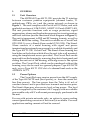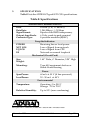
1
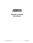
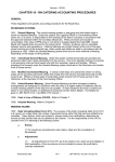
Type 400 T1 CSU
TYPE 400 T1 CHANNEL SERVICE UNIT
User's Manual
Type 400 T1 CSU Stand-Alone 1210015L1
Type 400 T1 CSU Circuit Pack 1210018L1
61210.015L1-1C
FCC regulations require that the following information be provided to the customer in
this manual:
1.
This equipment complies with Part 68 of the FCC rules. The required label
is inside the rear access door affixed to the lower side of the chassis.
2.
If your telephone equipment (TI CSU) causes harm to the telephone network, the
Telephone Company may discontinue your service temporarily. If possible, they will
notify you in advance. But if advance notice isn't practical, you will be notified as soon
as possible. You will be advised of your right to file a complaint with the FCC.
3.
Your telephone company may make changes in its facilities, equipment, operations,
or procedures that could affect the proper operation of your equipment. If they do, you
will be given advance notice so as to give you an opportunity to maintain uninterrupted
service.
If you experience trouble with this equipment (TI CSU), please contact ADTRAN at
(205) 971-7800 for repair/warranty information. The telephone company may ask
you
to disconnect this equipment from the network until the problem has been
corrected,
or until you are sure the equipment is not malfunctioning.
4.
5.
This unit contains no user serviceable parts.
6.
The following information is required when applying to your local telephone company
for leased line facilities. The user may select any one of the three via TI CSU option
switches.
Service Type
1.544 Mbps Digital Interface SF
1.544 Mbps Digital Interface ESF
1.544 Mbps Digital Interface ESF with B8ZS
Digital
Facility
Interface
Code
Service
Order
Code
Network
Jacks
04DU9-B
04DU9-C
04DU9-S
6.0F
6.0F
6.0F
RJ48C
RJ48C
RJ48C
FEDERAL COMMUNICATIONS COMMISSION
RADIO FREQUENCY INTERFERENCE STATEMENT:
This equipment has been tested and found to comply with the limits for a Class A digital device, pursuant to
Part 15 of the FCC rules. These limits are designed to provide reasonable protection against harmful
interference when the equipment is operated in a commercial environment. This equipment generates, uses,
and can radiate radio frequency energy and, if not installed and used in accordance with the instruction
manual, may cause harmful interference to radio interference. Operation of this equipment in a residential
area is likely to cause harmful interference in which case the user will be required to correct the interference
at his own expense.
SHIELDED CABLES MUST BE USED WITH THIS UNIT TO ENSURE COMPLIANCE WITH
CLASS A FCC LIMITS.
WARNING
Change or modification to this unit not expressly approved by the party responsible
for compliance could void user authority to operate the equipment.
November 1993
61210.015L1-1C
Page ii
WARRANTY AND CUSTOMER SERVICE
ADTRAN will replace or repair this product within five (5)
years from the date of shipment, if the product does not meet its
published specifications or if it fails while in service. For detailed
warranty, repair, and return information, refer to ADTRAN's
Equipment Warranty and Repair and Return Policy Procedure.
Return Material Authorization (RMA) is required prior to
returning equipment to ADTRAN.
For service, RMA requests, or further information, contact
one of the following numbers.
ADTRAN Customer Service:
RMA ............................... (205) 971-8722
Technical Support ........ (800) 726-8663
Sales ................................ (800) 827-0807
Repair and Return Address:
ADTRAN, Inc.
Customer Service Department
901 Explorer Boulevard
Huntsville, Alabama 35806-2807
November 1993
61210.015L1-1C
Page iii
This page left blank intentionally.
November 1993
61210.015L1-1C
Page iv
TABLE OF CONTENTS
1. GENERAL ................................................................................. 1
1.1
Unit Overview ................................................................... 1
1.2
Power Options ................................................................... 1
1.3
Alarms ................................................................................. 4
1.4
Loopback ............................................................................ 4
1.5
Line Build Out (LBO) ........................................................ 4
1.6
Automatically Setting Transmit LBO ............................. 5
2. INSTALLATION ..................................................................... 7
2.1
Setting the Options Switches ........................................... 7
2.2
Installing the Circuit Pack ................................................ 8
2.3
Powering the Unit (Stand-Alone Unit Only) ................ 9
2.4
Connecting the Network and CPE
(Stand-Alone Unit Only) ................................................ 10
2.5
Test and Monitor Access ................................................ 11
3.
TROUBLESHOOTING ........................................................ 13
4.
MAINTENANCE ................................................................... 15
5.
SPECIFICATIONS ................................................................ 17
FIGURES
Figure 1.
Figure 2.
Figure 3.
Figure 4.
Figure 5.
T1 CSU Application ....................................................
Type 400 T1 CSU Block Diagram ..............................
Switch Locations ..........................................................
Circuit Pack Connector Pin Assignments ................
Local Power Termination ...........................................
2
3
7
8
9
TABLES
Table A.
Table B.
Table C.
Table D.
Table E.
Network Transmit LBO .............................................. 5
Customer Transmit LBO ............................................ 5
TB1 Network and CPE Connections ....................... 10
Type 400 T1 CSU Troubleshooting Guide ............. 13
Specifications .............................................................. 17
November 1993
61210.015L1-1C
Page v
This page left blank intentionally.
November 1993
61210.015L1-1C
Page vi
1.
GENERAL
1.1
Unit Overview
The ADTRAN Type 400 T1 CSU provides the T1 interface
between customer premise equipment (channel banks, T1
multiplexers, PBXs, etc.) and the carrier network as shown in
Figure 1 . The unit complies with Part 68 of FCC Rules, and with
applicable sections of AT&T 62411, ANSI T1.102 and ANSI T1.403.
The unit provides functions such as surge protection, signal
regeneration, alarms and loopbacks necessary for circuit operation,
and fault isolation (see the functional block diagram in Figure 2 ).
The unit is transparent to ESF and SF framing formats, as well as
AMI and B8ZS line coding. The unit is available as a Circuit Pack
(1210.018L1) or as a Stand-Alone model (1210.015L). The StandAlone consists of a metal housing with signal and power
terminations (an external power supply is available if needed), and
the Type 400 T1 CSU Circuit Pack. The Stand-Alone housing has
four holes on the bottom which allow the unit to be wall mounted,
using the template and screws provided. The Circuit Pack can be
removed from the housing by removing the plastic front panel and
sliding the unit out of the housing, allowing access to the option
switches. The Circuit Pack, which can be purchased without the
housing, may also be used in a general purpose Type 400 NCTE
rack, or in a Type 400 T1 CSU slot of a channel bank such as the
ADTRAN ACT I.
1.2
Power Options
The Circuit Pack may receive power from the 48 V supply
of the Type 400 NCTE rack (local power), or from the carrier online (line power). The line power from the Telco is 60 mA of
constant current and is provided over transmit and receive pairs.
The Stand-Alone may also receive local or line power. The local
power is supplied by the customer's 48 V supply with an available
power cable or by a 48 V wall mount power supply purchased with
the unit.
For use with private networks only, an option to source sealing
current (preventing corrosion of the circuit) is available. For most
applications sealing current will not be sourced.
November 1993
61210.015L1-1C
Page 1
November 1993
61210.015L1-1C
4-Wire
Circuit
Channel Bank,
up to
Multiplexer, 655 Feet
PBX, etc...
CPE
Network
Provides
(Local Exchange Carrier,
Alarms,
Inter Exchange Carrier, or
Loopbacks,
Private Facilities)
Signal
Regeneration,
Surge
Protection,
and LBO
ADTRAN
T1-CSU
Provides
Alarms,
Loopbacks,
Signal
Regeneration,
Surge
Protection,
and LBO
ADTRAN
T1-CSU
Page 2
Figure 1. T1 CSU Application
Channel Bank,
Multiplexer,
PBX, etc...
CPE
November 1993
61210.015L1-1C
Page 3
NET
MON
POWER
SUPPLY
ALBO
LB
LOS MONITOR &
AIS INSERTER
LBO
(O-655 FEET)
TRANSMIT
TO NET
T1
R1
NET OUT
RECEIVE
FROM NET
T1
R1
SURGE
PROTECTION
POWER
LOCAL POWER
LBO
(0,7.5,15, 22.5 dB)
LOS MONITOR &
AIS INSERTER
EQUIPMENT
LOS
ALBO
ALARM
RELAY
Figure 2. Type 400 T1 CSU Block Diagram
LINE
LOCAL
MANUAL
LB
NETWORK
LOS
EQ
MON
C0MMON
T
R
EQ IN
NORMALLY CLOSED
NORMALLY OPEN
RECEIVE
FROM CPE
T1
R1
TRANSMIT
TO CPE
EQ OUT
LOOP CODE &
MANUAL LB
DETECTOR
NET IN
SURGE
PROTECTION
EQUIPMENT
NETWORK
1.3
Alarms
Both models provide alarms which facilitate
troubleshooting of the communication channel. Three visual alarms
are provided on the faceplate of the circuit pack. The first is the
POWER LED which indicates whether the unit is receiving power.
If the unit detects a loss of signal (LOS) from the network, it will be
indicated by NET LOS. This condition drives a double pole relay
alarm which can be tested using two of three pins on the terminal
block in the Stand-Alone. Pin 7 is the common connection, pin 6
normally opened, and pin 5 normally closed. On the card edge
connector of the Circuit Pack, pin 25 is the common connection, pin
29 normally opened, and pin 31 normally closed. If the unit detects
a loss of signal from the Customer Premise Equipment (CPE), the
EQ LOS LED alerts the user.
1.4
Loopback
Two forms of loopback are supported by the CSU, in which
the unit takes the signal received from the network and transmits
it back toward the network. An unframed all 1s signal is transmitted
toward the CPE, and the signal received from the CPE is ignored.
The first form, Manual Loopback, is activated by depressing the
MAN LBswitch on the front plate of the Circuit Pack. The unit will
stay in MAN LB until the switch is pressed again (switch is in the
out position). The second form of loopback is Network Loopback,
activated by sending the unit the 1-in-5 pattern (1000010000...) from
the network side for 5 seconds. This form of loopback can be
deactivated by sending the 1-in-3 pattern (100100100...) for 5 seconds.
Patterns may be unframed or framed (SF or ESF framing). Regardless
of which form of loopback is used, the LB LED on the front plate of
the Circuit Pack indicates the unit is in loopback.
1.5
Line Build Out (LBO)
Switch SW1 on the Circuit Pack selects LBO for the CSU.
Separate LBOs set transmit levels on network and CPE sides of the
CSU (see Tables A and B). On the network side, the amount of
attenuation is specified in dB, and is selected for 0, 7.5, 15 or 22.5 dB
of attenuation, as specified by the carrier. On the CPE side of the
CSU, the amount of attenuation is determined by setting the
maximum amount of cable between the CSU and CPE, available at
133, 266, 399, 533 and 655 feet.
November 1993
61210.015L1-1C
Page 4
Receivers on both sides of the CSU contain Automatic Line
Build Out circuitry compensating for cable signal loss.
Table A. Network Transmit LBO
SW1-1
SW1-2
SW1-3
Attenuation (dB)
Off
Off
Off
Off
On
On
On
Off
Off
N/A
On
Off
On
Off
N/A
0
7.5
15
22.5
Automatic
Table B. Customer Transmit LBO
SW1-4
SW1-5
SW1-6
Cable Length (feet)
Off
On
Off
On
Off
Off
On
On
Off
Off
On
Off
Off
Off
Off
0-133
134-266
267-399
400-533
534-655
1.6
Automatically Setting Transmit LBO
An additional option allows transmit LBO towards the
network to be set automatically by the CSU based on the level of the
signal received from the network. By setting SW1-1 for AUTO,
SW1-2 and SW1-3 are ignored and the transmit line build out is set
automatically. Setting SW1-1 to MANUAL allows SW1-2 and
SW1-3 to control the transmit line build out.
November 1993
61210.015L1-1C
Page 5
This page left blank intentionally.
November 1993
61210.015L1-1C
Page 6
2.
INSTALLATION
2.1
Setting the Option Switches
Remove the plastic front panel of the Stand-Alone housing
and slide the Circuit Pack out of the front of the unit. See Figure 3
for the location of switches SW1, SW3 and SW4. Switch SW1 selects
the LBO (see descriptions of SW1-1 through SW1-5 in Tables A and
B). Switch SW3 selects the powering option. If line power is
supplied by the carrier, place the switch in the LINE position, and
in LOCAL position if not. Switch SW4 selects whether sealing
current is sourced or not. For all applications other than a private
network, this switch should be placed in the SINK position. Only
if the CSU is to be used in a private network, and sealing current is
desired, should SW4 be in the SOURCE position.
SW1
Circuit Pack
SW3
SW4
Figure 3. Switch Locations
November 1993
61210.015L1-1C
Page 7
2.2
Installing the Circuit Pack
Figure 4 illustrates the edge connector pinout of the Circuit
Pack. If the Circuit Pack is to be used in an Type 400 NCTE rack or
a channel bank, these pin assignments should be consistent with
the rack or bank being used.
After the switches have been optioned correctly, insert the
Circuit Pack into the rack or bank by firmly pushing the Circuit
Pack into the appropriate slot. It should slide in smoothly and snap
into place.
Equipment T
Equipment R
Network R
Network T
-48V
Alarm 3
Alarm 2
Alarm 1
Signal Ground
Equipment R1
Network R1
Frame Ground
Network T1
Equipment T1
55
56
53
54
51
52
49
50
47
48
45
46
43
44
41
42
39
40
37
38
35
36
33
34
31
32
29
30
27
28
25
26
23
24
21
22
19
20
17
18
15
16
13
14
11
12
9
10
7
8
5
6
3
4
1
2
Figure 4. Circuit Pack Connector Pin Assignments
November 1993
61210.015L1-1C
Page 8
Powering the Unit (Stand-Alone Unit Only)
If the unit is line powered, slide the Circuit Pack back into
the housing, remove the power cable from the back of the housing
and refer to Section 2.05 . If the unit is to be locally powered from
the customer’s 48 V supply, connect the power cable as shown in
Figure 5 . Replace the cover and plastic front plate after connecting
the power cable. After supplying the unit with power, the POWER
LED on the front of the Circuit Pack should be on.
November 1993
Red
Black
Clear
FG
16
Page 9
Figure 5. Local Power Termination
Power
Cable
61210.015L1-1C
GND
Power
and
Signal
Termination
Board
1
-48V
White
TB1
Note: Strain relief tie mounts to the ground screw and loops around cable.
To Positive Terminal
To AC Ground
(Earth Ground)
Ground Screw
(Back of Base)
White
Black
Red
To Negative Terminal
TO ADTRAN Wall Mount or
Customer's 48V Supply
2.3
2.4
Connecting to the Network and CPE
(Stand-Alone Unit Only)
The rear panel of the Stand-Alone housing has two 8-pin
modular connectors. Plug network cables into connector labeled
NETWORK, and CPE cables into connector marked CUSTOMER.
If the modular connections are not to be used, then pins 10 - 13 on
the terminal block inside the housing are used for the network
connection, and pins 1 - 4 for CPE connections. These pins should
be connected as shown in Table C.
Table C. TB1 Network and CPE Connections
Pin
1
2
3
4
10
11
12
13
Function
CPE T1 - transmit to CPE (tip)
CPE R1 - transmit to CPE (ring)
CPE T - receive from CPE (tip)
CPE R - receive from CPE (ring)
NETWORK T1 - receive from NETWORK (tip)
NETWORK R1 - receive from NETWORK (ring)
NETWORK T - transmit to NETWORK (tip)
NETWORK R - transmit to NETWORK (ring)
Before connecting the CSU to the carrier network, notify
the carrier. With no signal present from the CPE, connect the CSU
to the network demarcation.
November 1993
61210.015L1-1C
Page 10
2.5
Test and Monitor Access
Six front panel Bantam jacks provide test and monitor
access for both the network and equipment side of the CSU. Signals
received from the network are monitored by the NET MONjack,
while the signal received from the CPE is monitored by the EQ
MONjack. These monitor jacks are resistively isolated from the
received signals, so the circuit can be monitored while in service.
The other four Bantam jacks are break and test jacks used for outof-service testing. These jacks bypass the connections of the modular
jacks. NET INand NET OUT are used to simulate network input
and output of the CSU. A T1 BERT (bit error rate test set) can be
used to simulate network, allowing the CPE testing. Likewise, EQ
IN and EQ OUT are used to simulate the CPE with a T1 BERT set,
allowing the network testing. The CSU on the other end of the
circuit could be looped up to test only the network. On either end
(the ability to send loop up and loop down codes is available with
most BERT sets).
November 1993
61210.015L1-1C
Page 11
This page left blank intentionally.
November 1993
61210.015L1-1C
Page 12
3.
TROUBLESHOOTING
Table D contains a list of symptoms and remedies for
problems possibly encountered during installation of the ADTRAN
Type 400 T1 CSU. If the symptom persists, contact ADTRAN
Customer Service Technical Support at (800) 726-8663 .
Table D. Type 400 T1 CSU
Troubleshooting Guide
Symptom
POWER LED
not On.
Remedy
If locally powered, ensure that SW3 is in the
LOCAL position. Verify that the power cable
is installed per Figure 5 .
NET LOS LED For the Stand-Alone, verify the cable from
is On.
network demarcation is in NETWORK
modular jack on the rear of the housing, or
tied to the TB1 per Table C. If all
connections appear correct, the far end CSU
can be looped (using a BERT tester to send
the loop up code or the manual loopback at
the other end) to isolate the problem to the
either the far end premises or the network.
If the problem persists after the loopback has
been activated, the problem is within the
network (or the far end CSU) and the carrier
should be notified. If the problem disappears
after loop up, then the cause is at the far end
customer premises.
EQ LOS LED
is On.
November 1993
For the Stand-Alone, verify the cable from
CPE is in CUSTOMER modular jack on the
back of the housing, or tied to TB1 per Table
C. If all connections appear correct, a BERT
set can be used in the NET IN and NET
OUT bantam jacks to further test the CPE.
61210.015L1-1C
Page 13
This page left blank intentionally.
November 1993
61210.015L1-1C
Page 14
4.
MAINTENANCE
The ADTRAN T1 CSU requires no routine maintenance to
operate. Repairs should not be performed in the field. Repair
services can be obtained by returning the unit to the ADTRAN
Repair Department after obtaining a Return Material Authorization
(RMA).
November 1993
61210.015L1-1C
Page 15
This page left blank intentionally.
November 1993
61210.015L1-1C
Page 16
5.
SPECIFICATIONS
Table E lists the ADTRAN Type 400 T1 CSU specifications.
Table E. Specifications
Network and Customer Interface
Line:
Data Rate:
Signal Format:
Output Amplitude:
Connector Type:
4-Wire (T, R, T1 and R1)
1.544 Mbps +/- 50 kbps
Bipolar with B8ZS transparency
6 Volts, peak-to-peak nominal
8-position modular (RJ48C)
Faceplate Indicators
Receiving line or local power
Loss of Signal from network
Loss of Signal from CPE
Network or manual loopback
POWER
NET LOS
EQ LOS
LB
Mechanical (Circuit Pack)
Size:
Weight:
1.40" Wide, 6" Diameter, 5.59" High
Mounting:
Type 400 equipment shelves or
Stand-Alone housing
Power
Span Power:
Local Power:
60 mA at 30 V (if line powered)
20 - 50 mA at 48 V
Environmental
Temperature:
Operating 0 to 50° C
Storage -20 to 70° C
Relative Humidity:
Up to 95% (non-condensing)
901 Explorer Drive • Huntsville, AL 35806-2807 • (205) 971-8000 • FAX (205) 971-8699
November 1993
61210.015L1-1C
Page 17
This page left blank intentionally.
November 1993
61210.015L1-1C
Page 18