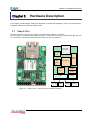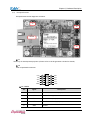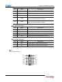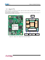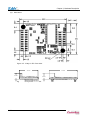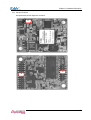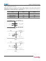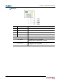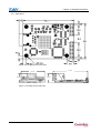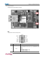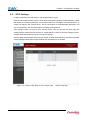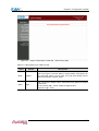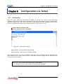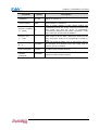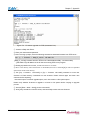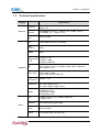
1
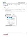
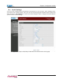
Eddy-Serial
User’s Guide
Ver 1.0
2007. 05. 25
Table of Contents
Contents
Table of Contents........................................................... I
Contents ................................................................ I
Figures ................................................................ IV
Tables .................................................................. V
Chapter 1. Introduction..................................................... 1-1
1.1 About this manual ................................................ 1-1
1.2 Who should read this manual ...................................... 1-1
1.3 Contents ......................................................... 1-2
1.4 Eddy Documents ................................................... 1-2
1.5 Technical Support ................................................ 1-3
Chapter 2. Getting Started.................................................. 2-1
2.1 Overview ......................................................... 2-1
2.2 Features ......................................................... 2-5
2.3 Package Checklist ................................................ 2-6
Eddy Package 2-6
CD-ROM (Utilities and documents) ........................................ 2-6
2.4 Applications ..................................................... 2-7
Factory / Industrial Automation .............................................
Home Appliances / Electronic Devices .......................................
Financial / Building Automation .............................................
OEM Device Server Distributors .............................................
2-7
2-7
2-7
2-7
Chapter 3. Hardware Description............................................. 3-1
3.1 Eddy-S1/Pin ...................................................... 3-1
3.1.1
Dimensions ....................................................... 3-2
3.1.2
Pin Specifications.................................................. 3-3
3.1.3
Connection Notes.................................................. 3-6
3.1.4
Serial Interface Selection........................................... 3-7
3.1.5
Terminal Resistors ................................................. 3-8
I
3.1.6
Terminal Resistor Installation Guide ..................................3-8
3.2 Eddy-S1/TTL ....................................................... 3-9
3.2.1
Dimensions .......................................................3-10
3.2.2
Pin Specifications .................................................3-11
3.2.3
Serial Interface Selection ..........................................3-16
3.3 Eddy-S1/DB9 ...................................................... 3-17
3.3.1
Dimensions .......................................................3-18
3.3.2
Pin Specifications .................................................3-19
3.4 Eddy-S2/Pin ...................................................... 3-23
3.4.1
Dimensions .......................................................3-24
3.4.2
Pin Specifications .................................................3-25
3.4.3
Serial Interface Selection ..........................................3-30
3.5 Eddy-S1/DB9-PoE .................................................. 3-32
3.5.1
Dimensions .......................................................3-33
3.5.2
Pin Specifications .................................................3-34
Chapter 4. Integration ...................................................... 4-1
4.1 Connection Guide .................................................. 4-1
4.2 First-time Bootup ................................................. 4-2
4.3 Connecting to Eddy with IP address ................................ 4-3
Chapter 5. Configuration via Web ............................................ 5-1
5.1 Connection ........................................................ 5-1
5.2 Setup Menu ........................................................ 5-2
5.3 Network Settings .................................................. 5-3
5.4 Serial Settings ................................................... 5-5
5.5 GPIO Settings .................................................... 5-10
5.6 Admin Settings ................................................... 5-12
5.7 Change Password .................................................. 5-13
5.8 Update Firmware .................................................. 5-14
5.9 Factory Default .................................................. 5-15
5.10 Save & Reboot .................................................... 5-16
Chapter 6. Configuration via Telnet ......................................... 6-1
6.1 Connection ........................................................ 6-1
6.2 View commands ..................................................... 6-2
6.3 Network commands .................................................. 6-3
6.4 Serial Commands ................................................... 6-4
6.5 GPIO commands ..................................................... 6-6
II
6.6 Username/Password Commands ....................................... 6-6
6.7 System Commands .................................................. 6-6
Chapter 7. Appendix......................................................... 7-1
7.1 Firmware Updates ................................................. 7-1
7.2 Technical Specifications ......................................... 7-5
7.3 Ordering Information ............................................. 7-7
7.4 FCC Statement .................................................... 7-8
III
Figures
Figure 3-1. Eddy-S1/Pin – Product Picture and Block Diagram ............... 3-1
Figure 3-2. Eddy-S1/Pin Front View ..................................... 3-2
Figure 3-3. Eddy-S1/Pin Side View....................................... 3-2
Figure 3-4. Eddy-S1/TTL – Product Picture and Block Diagram .............. 3-9
Figure 3-5. Eddy-S1/TTL Front View .................................... 3-10
Figure 3-6. Eddy-S1/TTL Side View ..................................... 3-10
Figure 3-7. Eddy-S1/DB9 – Product Picture and Block Diagram ............. 3-17
Figure 3-8. Eddy-S1/DB9 Front View .................................... 3-18
Figure 3-9. Eddy-S1/DB9 Side View ..................................... 3-18
Figure 3-10. Eddy-S2/Pin – Product Picture and Block Diagram ............ 3-23
Figure 3-11. Eddy-S2/Pin Front View................................... 3-24
Figure 3-12. Eddy-S2/Pin Side View.................................... 3-24
Figure 3-13. Eddy-S1/DB9-PoE – Product Picture and Block Diagram ....... 3-32
Figure 3-14. Eddy-S1/DB9-PoE Front View .............................. 3-33
Figure 3-15. Eddy-S1/DB9-PoE Side View ............................... 3-33
Figure 5-1. Eddy Login Page ............................................ 5-1
Figure 5-2. Main Page.................................................. 5-2
Figure 5-3. Network Settings Configuration Page .......................... 5-3
Figure 5-4. Eddy-S1/DB9, Eddy-S1/DB9-PoE serial communication setting page5-5
Figure 5-5. Eddy-S1/Pin, S1/TTL, S2/Pin serial communication setting page.. 5-6
Figure 5-6. Eddy-S1/PIN, Eddy-S1/TTL, Eddy-S2/PIN - GPIO Setting Page .. 5-10
Figure 5-7. Eddy-S1/DB9, Eddy-S1/DB9-PoE - GPIO Setting Page ........... 5-11
Figure 5-8. Admin Settings Page ....................................... 5-12
Figure 5-9. Change Password Setting Page............................... 5-13
Figure 5-10. Update Firmware Setting Page ............................ 5-14
Figure 5-11. Factory Default Setting Page .............................. 5-15
Figure 5-12. Save & Reboot Setting Page ............................... 5-16
Figure 6-1. Connection via Telnet ....................................... 6-1
IV
Figure 7-1. Firmware updates via FTP ................................... 7-1
Figure 7-2. Firmware Update via Telnet ................................. 7-2
Figure 7-3.Firmware upgrade via TFTP................................... 7-3
Figure 7-4. Firmware upgrade via TFTP (Command Line) .................. 7-4
Tables
Table 1-1. Eddy Documents ........................................... 1-2
Table 5-1. Main features of Setup Menu................................. 5-2
Table 5-3. Main features for NMS Configuration .......................... 5-4
Table 5-5. Main features for GPIO Settings ............................. 5-11
Table 5-6. Main features for Admin Setting ............................. 5-12
Table 5-7. Main features for Save & Reboot Save & Reboot ............... 5-16
Table 6-1. View commands ............................................ 6-2
Table 6-2. Network general configuration commands ..................... 6-3
Table 6-3. Network NMS configuration commands ........................ 6-3
Table 6-4. Serial commands ........................................... 6-4
Table 6-5. GPIO commands ............................................ 6-6
Table 6-6. User/Password configurations................................ 6-6
Table 6-7. System Commands.......................................... 6-6
V
Chapter 1. Introduction
Chapter 1.
Introduction
SystemBase Embedded Module lineup is composed of largely three catagories; The Eddy Serial Series,
Eddy-DIO Series and Eddy CPU Series. This manual gives an introduction to the Eddy Serial Series.
1.1
About this manual
This manual includes all necessary information from installation to operating Eddy-Serial Series (EddyS1/Pin, Eddy-S1/TTL, Eddy-S1/DB9, Eddy-S2/Pin, Eddy-S1/DB9-PoE). Setting Eddy’s configurations,
status monitoring, firmware update, and other administration work are also included, H/W level
integration and S/W setting information can also be found.
1.2
Who should read this manual
This guide is designed for Eddy-Serial users and administrators. It is strongly recommended that
anyone trying to apply, use, and maintain Eddy read this document. It will be a great starting point for
any administrator who wants to easily monitor and control Eddy and its connected devices.
1-1
Chapter 1. Introduction
1.3
Contents
Chapter 1. Introduction is a preface with general information and introductory notices.
Chapter 2. Getting Started gives a brief introduction to Eddy series, including features and
applications.
Chapter 3. Hardware Descriptions explains the layout and pin specifications with block diagram and
drawings.
Chapter 4. Integration assists you connecting Eddy to serial and network environment. It covers first
time boot-up and status check procedures.
Chapter 5. Configuration via Web provides ways to configure and to connect Eddy via web browser.
Chapter 6. Configuration via Telnet provides commands and its explanation to configure and to
connect Eddy via web Telnet.
Chapter 7. Appendix provides firmware update guides and detailed technical specifications .
1.4
Eddy Documents
The following table summarizes documents included in the Eddy document set.
Table 1-1. Eddy Documents
Document
User’s Guide
(Serial, DIO, CPU)
Programmer’s Guide
Description
Eddy’s Configuration, and Management Information
Programmer’s application development guide, including indepth approach to compiling, linking, creating and uploading
firmware
API reference is included with a list of available functions
for customized application programming
Portview User’s Manual
Guide for SystemBase device server management application
Portview
COM Port Redirector
User Manual
Guide for SystemBase COM Port Redirector
General information on Eddy or embedded device servers can be obtained at our website at
http://www.sysbas.com/. Latest documents, software and firmware downloads are available.
Other relevant documents are as follows:
1-2
Chapter 1. Introduction
Document
Description
Eddy Spec Sheet
(Serial, DIO, CPU)
Eddy Specifications
Eddy White Paper
An introductory reading for anyone new to embedded device
server.
Deals with background, history, market environment, and
technology
Eddy Application Notes
Various applications of Eddy presented in diagrams and images
All documents are updated promptly, so check for the recent document updates. The contents in
these documents are subject to change without a prior notice.
1.5
Technical Support
You can reach our tech support by following 3 ways;
1. Visit us at http://www.sysbas.com/ and go to ‘Technical Support’menu. FAQ and questions can be
reviewed and submitted.
2. E-mail our technical support team to [email protected]. Any kind of inquiries, requests, and
comments are welcomed.
3. Call us at our customer center at 82-2-855-0501 for immediate support.
Our technical support team will kindly help you get over with the problem.
Copyright 2006 SystemBase Co., Ltd. All rights reserved.
Homepage: http://www.sysbas.com/
Tel: 02-855-0501
Fax: 02-855-0580
16F Dearung Post Tower-1, 212-8
Guro-dong, Guro-gu, Seoul, Korea
1-3
Chapter 1. Introduction
Intentionally left blank
1-4
Chapter 2. Getting Started
Chapter 2.
Getting Started
Welcome to Eddy! This chapter includes Eddy series overview, main and distinctive features, package contents
for each product, and application fields.
2.1
Overview
There are 5 modules in Eddy-Serial Series; Eddy-S1/Pin, Eddy-S1/TTL, Eddy-S1/DB9, Eddy-S2/Pin, and EddyS1/DB9-PoE.
Each module includes default applications for serial and LAN communication, and supports plug-and-play
features. By switching to the custom mode, users can program any application and upload it on to the module.
This application then is executed on the module. In order to write and compile programmer’s source code,
Software Development Kit (SDK) is required. SDK is included in the Development Kit package. Please refer to
Programming Guide included in the Development Kit for detailed information on the SDK.
SDK is not necessary for users using Eddy in default presettings.
◆ Eddy-S1/Pin
RJ-45 Ethernet port is included to provide direct connection to network.
For serial communication, RS232/422/485 interface is provided through pin header, and users can easily
connect it to either customized connectors or to standard DB9 and DB25 connectors.
External power of 3.3V or 5V can be fed to the module through pin headers.
Please check labeled input voltage on top of the module before supplying power. Improper voltage feed may
damage the module.
2-1
Chapter 2. Getting Started
◆ Eddy-S1/TTL
Pin header interface provides Ethernet connectivity. Users can connect it either to standard RJ-45 port or to
any customized LAN interface connector.
For serial communication, RS232/422/485 interface is provided through pin header in 5V TTL signals, and users
can implement their own UART controller hardware to convert the signals into RS232/422/485 lines.
External power of 3.3V or 5V can be fed to the module through pin headers.
Please check labeled input voltage on top of the module before supplying power. Improper voltage feed may
damage the module.
◆ Eddy-S1/DB9
RJ-45 Ethernet port provides direct connection to network.
For serial communication, RS232/422/485 interface is provided through DB9 connector, providing simple
connectivity to field devices.
5V DC power input is required for this module proper operate correctly. Please check labeled input voltage on
top of the module before supplying power. Improper voltage feed may damage the module.
2-2
Chapter 2. Getting Started
◆ Eddy-S2/Pin
This module is a 2-serial port version of Eddy-S1/Pin. SystemBase designed UART 16C1054, with large FIFO size
of 256 bytes, is used in the module to maximize the performance of serial communication.
External power of 3.3V or 5V can be fed to the module through pin headers.
Please check labeled input voltage on top of the module before supplying power. Improper voltage feed may
damage the module.
◆ Eddy-S1/DB9-PoE
This module can operate as a powered device (PD), which accepts power input from the twisted pair Category
5 Ethernet cable as specified in IEEE 802.3af Power-over-Ethernet (PoE) standard.
With an auxiliary 5V DC power jack, power supply can be automatically channeled to 5V adaptor when PSE
(Power Sourcing Equipment) is out of order. Seamless power supply is guaranteed. PSE power can be used
again when the PSE resumes to normal operation.
RS232/422/485 interface is supported in a single module, with a DB9 male connector. RS232/422/485 can be
configured with software, including Web or Telnet interface.
2-3
Chapter 2. Getting Started
◆ Eddy Development Kit (Eddy DK)
Eddy Development Kit (Eddy DK) helps programmers to test and customizes their own Eddy applications easily.
The kit includes evaluation board, all necessary connectors, and programming environment with
documentations and guidelines. Please refer to Programming Guide included in the Development Kit for
detailed information on the DK.
◆ Selection Guide
Eddy-S1/Pin-3
Eddy-S1/Pin-5
Eddy-S1/TTL-3
Eddy-S1/TTL-5
EddyS1/DB9
Eddy-S1/DB9PoE
CPU
ARM940T(168MHz)
Memory
4MB Flash / 8 MB SDRAM
Serial Interface
RS232/422/485
TTL
Serial Port
Ethernet
Interface
1 * Pin Header
1 * TTL
Ethernet Port
1 * RJ45
1 * TTL
GPIO
4
3.3V or 5V pin
input
55 x 38 mm
Power Input*
Dimensions
RS232/422/
485
1 * DB9
Eddy-S2/Pin-3
Eddy_S2/Pin-5
RS232/422/485
RS232/422/485
1 * DB9
2 * Pin Header
1 * RJ45
1 * RJ45
1 * RJ45
9
-
-
4
3.3V or 5V pin
input
50 x 35 mm
5V power
jack
62 x 45 mm
5V power jack
or PoE(48V)
70 x 50 mm
3.3V or 5V pin
input
62 x 45 mm
10BASE-T/100BASE-TX
Programmability
Yes
Yes
Yes
Yes
Yes
* Power Input indicated as 3.3V or 5V means that there are two different types of modules
available (the input is indicated in a label attached on the top of the module)
2-4
Chapter 2. Getting Started
◆ Eddy Software Architecture
2.2
Features
Various features of Eddy make it a universal yet distinctive embedded solution.
Below lists main features of Eddy Serial Series. Others will explicitly appear throughout this guide.
-
Premium-level hardware with ARM9 168MHz CPU, 4MB Flash, and 8MB SDRAM
Selectable RS232/422/485 interfaces
Max 921.6Kbps serial speed
Program and run your own application
SystemBase SDK and API support for application programming (included in Development Kit)
Small size to fit in to any hardware
10/100Mbps Ethernet port with transformer
SystemBase COM Port Redirector for better adaptability
Extensive configuration and monitoring with Portview
Firmware upload with Web, FTP, and TFTP
Configuration with Web, Telnet, SNMP, and Portview
Various customizing options
Standard Linux environment for openness in executable applications
2-5
Chapter 2. Getting Started
-
2.3
Multiple Programmable IO pins for customized applications
Package Checklist
Eddy package is composed of following components. Make sure every component is included with your
package.
Eddy Package
All module packages include a module and a CD with utilities and documents.
Module 1pc (One among Eddy-S1/Pin, Eddy-S1/TTL, Eddy-S1/DB9, Eddy-S2/Pin, Eddy-S1/DB9-PoE)
CD-ROM (Utilities and documents)
2-6
Chapter 2. Getting Started
2.4
Applications
Eddy can be applied to many practical applications in various fields. Some are presented below.
Factory / Industrial Automation
PLC, Robot arms, Human-Machine Interface, Warehouse rails
Medical instruments, Inspection equipment controllers
Alarming units
Home Appliances / Electronic Devices
Power controller, Gaming machines
Scales, Gas detection units, Water & pollution metering devices
Data collection and distribution units
Financial / Building Automation
Card readers, Barcode scanners, Kiosks, Point-Of-Sale related devices
Serial printers, Cash registers, Credit card authorization terminals
Biometric detection units, Security devices
OEM Device Server Distributors
OEM device server with distributor’s own case & brand
Ready-to-go device or customized application / setup mode can be inserted
2-7
Chapter 2. Getting Started
Intentionally left blank
2-8
Chapter 3. Hardware Description
Chapter 3.
Hardware Description
This chapter provides Eddy’s hardware information, including block diagram, layout, pin specifications,
dimensions and other hardware-related issues.
3.1
Eddy-S1/Pin
Ethernet LAN port is in RJ-45 form factor to provide direct network connection.
One serial port is provided in pin header interface, configurable to use any of RS232/422/485. Pins can
be connected to any kind of external serial interface of user’s preference.
RJ 45 with
Transformer
10/100M
Ethernet
PHY
8 MB
SDRAM
ARM 9 CPU
4MB
Flash
16C550
UART
RS 422 /485
Driver
RS 232
Driver
14 Pin
3.3V / 5V
Reset
10 Pin
4 GPIO
Serial #1
Figure 3-1. Eddy-S1/Pin – Product Picture and Block Diagram
3-1
Chapter 3. Hardware Description
3.1.1 Dimensions
Figure 3-2. Eddy-S1/Pin Front View
39 mm
18 mm
60 mm
18 mm
Figure 3-3. Eddy-S1/Pin Side View
3-2
Chapter 3. Hardware Description
3.1.2
Pin Specifications
Pin Specification and its usages are as follows.
J1
J2
J2
RJ-45
J4
◆ J1
Used only for development purposes. (Please refer to the Programmer’s Guide for details)
◆ J2
Serial 10-pin header connector
DCD
1
2
RXD
TXD
3
4
DTR
GND
5
6
DSR
RTS
7
8
CTS
USBN
9
10
USBP
◇ J2 : RS232
Pin
Signal
Description
1
DCD
Data Carrier Detection (Input)
2
RXD
Receive Data (Input)
3
TXD
Transmit Data (Output)
4
DTR
Data Terminal Ready (Output)
5
GND
Ground
3-3
Chapter 3. Hardware Description
Pin
Signal
Description
6
DSR
Data Set Ready (input)
7
RTS
Request to Send (Output)
8
CTS
Clear to Send (Input)
9
USBN
Differential data negative on USB port
(Used only for development purposes)
10
USBP
Differential data positive on USB port
(Used only for development purposes)
◇ J2 : RS422 Full Duplex
Pin
Signal
Description
2
RXD+
Receive differential data positive (Input)
3
TXD+
Transmit differential data positive (Output)
6
RXD-
Receive differential data negative (input)
7
TXD-
Transmit differential data negative (Output)
◇ J2 : RS485 Half Duplex
Pin
Signal
Description
3
TRX+
Transmit/Receive differential data positive
7
TRX-
Transmit/Receive differential data negative
◆ J4
14-pin header connector
3-4
INF_1
1
2
VCC
INF_0
3
4
VCC
NC
5
6
NC
RDY#
7
8
RST#
GND
9
10
GND
PIO3
11
12
PIO2
PIO1
13
14
PIO0
Chapter 3. Hardware Description
Pin
Signal
Description
1
INF_1
Serial Interface Select 1
Serial interface can be set up in combination with INF_0.
When RS232, INF[1:0] = ‘00’,
When RS422, INF[1:0] = ‘01’,
When RS422, INF[1:0] = ‘10’
(Make sure that‘0’ is connected to either open or GND, while ‘1’is
connected to 3.3V )
2
VCC
Make sure that correct input voltage is provided.
(Two types of model ,5V and 3.3V modules are available )
3
INF_0
Serial Interface Select 0
Serial interface can be set up in combination with INF_1.
4
VCC
Eddy-S1/Pin-3 requires DC 3.3V power supply
Eddy-S1/Pin-5 requires DC 5V power supply
(Two types of model ,5V and 3.3V modules are available )
5
NC
No Connection
6
NC
No Connection
Ready indicator (Active low output)
Processor status can be indicated, when connected as below.
7
RDY#
8
RST# *
9
GND
Ground
10
GND
Ground
11
PIO3
Programmable I/O 3 (user-defined I/O)
12
PIO2
Programmable I/O 2 (user-defined I/O)
13
PIO1
Programmable I/O 1 (user-defined I/O)
14
PIO0
Programmable I/O 0 (user-defined I/O)
Connection to external reset switch (Input)
As reset logic is built-in, this pin can be connected directly to the
switch without any additional circuit.
※Eddy-S1/Pin V1.0 users must connect 3.3V input to RST# pin.
3-5
Chapter 3. Hardware Description
◆ RJ-45 Ethernet
Pin
Signal
1
TXD+
Transmit Data +
2
TXD-
Transmit Data -
3
RXD+
Receive Data +
6
RXD-
Receive Data -
LED
3.1.3
Description
Description
Left Green
On: 100Base-TX Link is available
Blinking: Data is transmitted or received.
Right Yellow
On: 10Base-T Link is available
Blinking: Data is transmitted or received.
Connection Notes
Eddy-S1/Pin V1.0 users must connect 3.3V, GND, and RST# pins to ensure a proper connection.
RST# (Reset) pin needs to be supplied with high signal at normal operation, and after longer than
200ms of low signal, the module will be reset. In order to implement reset function in Eddy, you must
turn the switch ON and supply input power.
3-6
Chapter 3. Hardware Description
3.1.4 Serial Interface Selection
Eddy-S1/Pin supports hardware configuration of RS232 / RS422 / RS485, and each interface can be
configured by a combination of INF_1 and INF_0 signals.
Serial
INF_1
INF_0
RS232
Low
Low
RS422 Full Duplex
Low
High
RS485 Half Duplex
High
Low
Eddy
User Board
INF_1 ①
Pin①, ③ all Open
(Not Connect)
INF_0 ③
RS232
User Board
Eddy
3.3V
INF_1 ①
INF_0 ③
* Pin ①은 open
RS422
User Board
Eddy
3.3V
INF_1 ①
INF_0 ③
* Pin ③은 open
RS485
3-7
Chapter 3. Hardware Description
3.1.5 Terminal Resistors
Terminal Resistors are installed in RS422 or RS485 communication to prevent noise and distortion of
long distance data transfer. They help by matching impedance in communication line, and normally 120
ohm resistors are used. The decision to use terminal resistor lies with the user, and one may choose to
either install or not install terminal resistors in RS422 or RS485 mode. Installation can be done by
connecting RX+ and RX- pin on J2 pin header to the resistor if in RS422 mode, or TRX+ and TRX- pin in
RS485 mode.
3.1.6 Terminal Resistor Installation Guide
◆ RS422
Install terminal resistors at each end (terminal)
When using RS422 Point to Point Mode
When using RS422 Multi-Drop Mode
Terminal REG
RS422 Device A
RS422 Device B
RS422 Master Device
RS422 Slave Device A
120R
TXD+
RXD+
TXD+
RXD+
TXD-
RXD-
TXD-
RXD-
RXD+
TXD+
RXD+
TXD+
RXD-
TXD-
RXD-
TXD-
120R
120R
Terminal REG
Terminal REG
RS422 Slave Device B
RXD+
RXDTXD+
TXD-
RS422 Slave Device N
120R
RXD+
RXD-
Terminal REG
TXD+
TXD-
.
RS485
Install terminal resistors only at each end (not in the middle ones in Multi-Drop structure)
TRXD-
TRXD+
RS485 Device D
TRXD-
TRXD+
RS485 Device C
TRXD-
TRXD+
RS485 Device B
Terminal REG
RS485 Device A
RS485 Device N
120R
TRXD+
TRXD+
TRXD-
TRXD-
RS485 Device E
3-8
RS485 Device F
TRXD-
TRXD+
TRXD-
TRXD+
TRXD-
Terminal REG
TRXD+
120R
RS485 Device G
Chapter 3. Hardware Description
3.2
Eddy-S1/TTL
Ethernet LAN port is provided in pin header. Users can connect these pins either directly to Ethernet
device interface or to RJ-45 connector.
One serial port is provided in TTL interface, and users can attach these pins to their UART controller to
implement RS232/422/485 communication.
Ethernet
Interface
16 pins
10 / 100 M
Ethernet
PHY
ARM 9 CPU
8 MB
SDRAM
4 MB
Flash
24 Pin
3.3V / 5V
Reset
9 GPIO
Serial #1
Figure 3-4. Eddy-S1/TTL – Product Picture and Block Diagram
3-9
Chapter 3. Hardware Description
3.2.1 Dimensions
Figure 3-5. Eddy-S1/TTL Front View
36 mm
18 mm
Figure 3-6. Eddy-S1/TTL Side View
3-10
50 mm
18 mm
Chapter 3. Hardware Description
3.2.2 Pin Specifications
Pin Specification and its usages are as follows
J1
J3
J2
3-11
Chapter 3. Hardware Description
◆ J1
Used only for development purposes. (Please refer to the Programmer’s Guide for details)
◆ J2
Ethernet & GPIO header connector
3-12
NC
16
15
NC
PIO9
14
13
PIO8
PIO7
12
11
PIO6
PIO5
10
9
NC
GND
8
7
GND
LAN_10M
6
5
LAN 100M
TPRX-
4
3
TPTX-
TPRX+
2
1
TPTX+
Chapter 3. Hardware Description
※
Pin
G
P 1
I
O
5 2
Signal
TPTX+
TPRX+
~
G 3
P
I
O 4
9
a
r 5
e
n
o
t 6
u
s 7
e
d 8
. 9
TPTX-
TPRX-
LAN 100M
LAN 10M
Description
Transmit Data(+) from the PHY chip
When implementing Ethernet, transformer and RJ45 connector
need to be implemented separately.
Receive Data(+) from the PHY chip
When implementing Ethernet, transformer and RJ45 connector
need to be implemented separately.
Transmit Data(-) from the PHY chip
When implementing Ethernet, transformer and RJ45 connector
need to be implemented separately.
Receive Data(-) from the PHY chip
When implementing Ethernet, transformer and RJ45 connector
need to be implemented separately.
LED signal associated with the PHY chip embedded in the
module
On: 100Base-TX Link is available
Blinking: Data is transmitted or received.
LED signal associated with the PHY chip embedded in the
module
On: 10Base-T Link is available
Blinking: Data is transmitted or received.
GND
Ground
GND
Ground
NC
No Connection
10
GPIO5
Programmable I/O 5
11
GPIO6
Programmable I/O 6
12
GPIO7
Programmable I/O 7
13
GPIO8
Programmable I/O 8
14
GPIO9
Programmable I/O 9
15
NC
No Connection
16
NC
No Connection
3-13
Chapter 3. Hardware Description
◆ J3
Serial 24-pin Connector
3-14
USBN
USBP
1
2
DCD
3
4
RXD
TXD
5
6
DTR
GND
7
8
DSR
RTS
9
10
CTS
ForceOff#
11
12
NC
INF_1
13
14
VCC
INF_0
15
16
VCC
NC
17
18
NC
RDY#
19
20
RST#
PIO3
21
22
PIO2
PIO1
23
24
PIO0
Pin
Signal
Description
1
USBP
Differential data positive for USB port
(Used only for development purposes)
2
USBN
Differential data negative for USB port
(Used only for development purposes)
3
DCD
UART Data Carrier Detection (Input)
4
RXD
UART Receive Data (Input)
5
TXD
UART Transmit Data (Output)
6
DTR
UART Data Terminal Ready (Output)
7
GND
Ground
8
DSR
UART Data Set Ready (input)
9
RTS
UART Request to Send (Output)
10
CTS
UART Clear to Send (Input)
11
ForceOff#
12
NC
RS232 Driver IC shutdown signal
Used only when RS232/RS422/RS485 IC needs to be
implemented on a single board. (Applicable only to ICs with
Shutdown function).
No Connection
Chapter 3. Hardware Description
Pin
Signal
Description
13
INF_1
Serial Interface Select 1
Serial interface can be set up in combination with INF_0 (pin
15)
When RS232, INF[1:0] = ‘00’,
When RS422, INF[1:0] = ‘01’,
When RS422, INF[1:0] = ‘10’
(Make sure that‘0’ is connected to either open or GND, while
‘1’is connected to 3.3V)
14
VCC
Make sure that correct input voltage is provided.
(Two types of model ,5V and 3.3V modules are available )
15
INF_0
Serial Interface Select 0
Serial interface can be set up in combination with INF_1.
16
VCC
Eddy-S1/TTL-3 requires DC 3.3V power supply
Eddy-S1/TTL-5 requires DC 5V power supply
(Two types of model ,5V and 3.3V modules are available )
17
NC
No Connection
18
NC
No Connection
Ready indicator (Active low output)
Processor status can be indicated, when connected as below.
19
RDY#
20
RST#
Connected to external reset switch (Input)
As reset logic is built-in, this pin can be connected directly to
the switch without any additional circuit..
21
PIO3
Programmable I/O 3 (user-defined I/O)
22
PIO2
Programmable I/O 2 (user-defined I/O)
23
PIO1
Programmable I/O 1 (user-defined I/O)
24
PIO0
Programmable I/O 0 (user-defined I/O)
3-15
Chapter 3. Hardware Description
3.2.3
Serial Interface Selection
Since serial signals are provided in TTL level, UART controller or line driver circuit must be
implemented to enable communication in RS242/422/485. Please note that the serial interface is
determined by the combination of INF_1 and INF_0 pins.
Serial
INF_1
INF_0
RS232
Low
Low
RS422 Full Duplex
Low
High
RS485 Half Duplex
High
Low
Eddy
User Board
INF_1 ①
Pin①, ③ all Open
(Not Connect)
INF_0 ③
RS232
Eddy
User board
3.3V
INF_1 ①
INF_0 ③
* Pin ① open
RS422
User Board
Eddy
3.3V
INF_1 ①
INF_0 ③
* Pin ③ open
RS485
3-16
Chapter 3. Hardware Description
3.3
Eddy-S1/DB9
Ethernet LAN port is in RJ-45 form factor to provide direct network connection.
One serial port is provided in DB9 interface with configurable RS232/422/485. The serial interface can
be configured by software, through web configuration interface.
5 V DC
RJ 45 with
Transformer
Reset
Button
10 /100 M
Ethernet
PHY
8 MB
SDRAM
ARM 9 CPU
4 MB
Flash
RS 422 / 485
Driver
16 C 550
UART
RS 232
Driver
DB 9
Serial
Signals
Figure 3-7. Eddy-S1/DB9 – Product Picture and Block Diagram
3-17
Chapter 3. Hardware Description
3.3.1 Dimensions
Figure 3-8. Eddy-S1/DB9 Front View
73 mm
45 mm
22 mm
Figure 3-9. Eddy-S1/DB9 Side View
3-18
22 mm
Chapter 3. Hardware Description
3.3.2 Pin Specifications
Pin Specification and its usages are as follows
J1
RJ-45
J2
DB9
Power Jack
LED
◆ Power JACK
Contact
Polarity
Center
+5VDC ± 5%(over 400mA )
Outer
Ground
3-19
Chapter 3. Hardware Description
◆ J1
Used only for development purposes. (Please refer to the Programmer’s Guide for details)
◆ J2
USB Connector
Pin
Signal
Description
1
NC
2
USBN
USB port 의 differential data negative
(Used only for development purposes)
3
USBP
USB port 의 differential data positive
(Used only for development purposes)
4
GND
Ground
No Connection
◆ DB9
Serial Connector
◆ RS232
3-20
Pin
Signal
Description
1
DCD
Data Carrier Detection (Input)
2
RXD
Receive Data (Input)
3
TXD
Transmit Data (Output)
4
DTR
Data Terminal Ready (Output)
5
GND
Ground
6
DSR
Data Set Ready (input)
7
RTS
Request to Send (Output)
Chapter 3. Hardware Description
Pin
Signal
Description
8
CTS
Clear to Send (Input)
9
RI
Ring Indicator (Input)
◆ RS485 Half Duplex
Pin
Signal
Description
3
TRX+
Transmit/Receive differential data positive
7
TRX-
Transmit/Receive differential data negative
◆ RS422 Full Duplex
Pin
Signal
Description
2
RXD+
Receive differential data positive (Input)
3
TXD+
Transmit differential data positive (Output)
6
RXD-
Receive differential data negative (input)
7
TXD-
Transmit differential data negative (Output)
Pin
Signal
1
POWER
LED ON when power is on
2
READY
Indicates the processor status
3
TXD
LED ON when serial data is transmitted
4
RXD
LED ON when serial data is received.
◆ LED
Description
3-21
Chapter 3. Hardware Description
◆ RJ-45 Port
Pin
Signal
1
TXD+
Transmit Data +
2
TXD-
Transmit Data -
3
RXD+
Receive Data +
6
RXD-
Receive Data -
LED
3-22
Description
Description
Left Green
On: 100Base-TX Link is available
Blinking: Data is transmitted or received.
Right Yellow
On: 10Base-T Link is available
Blinking: Data is transmitted or received.
Chapter 3. Hardware Description
3.4
Eddy-S2/Pin
Ethernet LAN port is in RJ-45 form factor to provide direct network connection.
Two serial ports are provided in pin header interface, each configurable to use any of RS232/422/485.
Pins can be connected to any kind of external serial interface of user’s preference.
RJ 45 with
Transformer
10 /100 M
Ethernet
PHY
8 MB
SDRAM
4 MB
Flash
16 C 1054
UART
ARM 9 CPU
RS 422 /485
Driver
RS 422 / 485
Driver
RS 232
Driver
RS 232
Driver
20 pins
14 pins
Serial # 2
3 .3 V / 5 V
Reset
4 GPIO
Serial # 1
Figure 3-10. Eddy-S2/Pin – Product Picture and Block Diagram
3-23
Chapter 3. Hardware Description
3.4.1 Dimensions
Figure 3-11. Eddy-S2/Pin Front View
67 mm
45 mm
18 mm
Figure 3-12. Eddy-S2/Pin Side View
3-24
18 mm
Chapter 3. Hardware Description
3.4.2 Pin Specifications
Pin Specification and its usages are as follows.
J1
J4
◆ J1
14-pin header connector (2mm pin pitch)
Pin
1
INF_1
1
2
VCC
INF_0
3
4
VCC
NC
5
6
NC
RDY#
7
8
RST#
USBP
9
10
USBN
GPIO3
11
12
GPIO2
GPIO1
13
14
GPIO0
Signal
Description
INF_1
Serial Interface Select 1
Serial interface can be set up in combination with
INF_0
(pin 3)
When RS232, INF[1:0] = ‘00’
When RS422, INF[1:0] = ‘01’
When RS422, INF[1:0] = ‘10’
3-25
Chapter 3. Hardware Description
Pin
Signal
Description
(Make sure that‘0’ is connected to either open or GND,
while ‘1’is connected to 3.3V)
2
VCC
Make sure that correct input voltage is provided.
(Two types of model ,5V and 3.3V modules are
available )
3
INF_0
Serial Interface Select 0
Serial interface can be set up in combination with
INF_1.
4
VCC
Eddy-S2/Pin-3 requires DC 3.3V power supply
Eddy-S2/Pin-5 requires DC 5V power supply
(Two types of model ,5V and 3.3V modules are
available )
5
NC
No Connection
6
NC
No Connection
Ready indicator (Active low output)
Processor status can be indicated, when connected as
below.
3-26
7
RDY#
8
RST#
Connected to external Reset switch (Input)
As reset logic is built-in, this pin can be connected
directly to the switch without any additional circuit.
9
USBP
Differential data positive on USB port
(Used only for development purposes)
10
USBN
Differential data negative on USB port
(Used only for development purposes)
11
GPIO3
Programmable I/O 3 (User defined I/O)
12
GPIO2
Programmable I/O 2 (User defined I/O)
13
GPIO1
Programmable I/O 1 (User defined I/O)
14
GPIO0
Programmable I/O 0 (User defined I/O)
Chapter 3. Hardware Description
◆ J4
Serial 20-pin header connector (2mm pin pitch)
INF_3
1
2
VCC
INF_2
3
4
VCC
DCD0
5
6
RXD0
TXD0
7
8
DTR0
GND
9
10
DSR0
RTS0
11
12
CTS0
DCD1
13
14
RXD1
TXD1
15
16
DTR1
GND
17
18
DSR1
RTS1
19
20
CTS1
◇ J4 : RS232
Pin
Signal
Description
Serial Interface Select 3 (Port #2)
Serial interface can be set up in combination with
INF_2. (pin 3)
When using RS232, INF[1:0] = ‘00
When using RS422, INF[1:0] = ‘01’
When using RS485, INF[1:0] = ‘10’
(Make sure that ‘0’ is connected to either open or GND,
while ‘1’is connected to 3.3V
Make sure that correct input voltage is provided.
(Two types of models, 5V and 3.3V modules are
available )
1
INF_3
2
VCC
3
INF_2
Serial Interface Select 2
Serial interface can be set up in combination with
INF_3.
4
VCC
Eddy-S2/Pin-3 requires DC 3.3V power supply
Eddy-S2/Pin-5 requires DC 5V power supply.
(Two types of models, 5V and 3.3V modules are
available )
5
DCD 0
Port #1 - Data Carrier Detection (Input)
6
RXD 0
Port #1 - Receive Data (Input)
7
TXD 0
Port #1 - Transmit Data (Output)
8
DTR 0
Port #1 - Data Terminal Ready (Output)
9
GND
Ground
3-27
Chapter 3. Hardware Description
Pin
Signal
Description
10
DSR 0
Port #1 - Data Set Ready (input)
11
RTS 0
Port #1 - Request to Send (Output)
12
CTS 0
Port #1 - Clear to Send (Input)
13
DCD 1
Port #2 - Data Carrier Detection (Input)
14
RXD 1
Port #2 - Receive Data (Input)
15
TXD 1
Port #2 - Transmit Data (Output)
16
DTR 1
Port #2 - Data Terminal Ready (Output)
17
GND
Ground
18
DSR 1
Port #2 - Data Set Ready (input)
19
RTS 1
Port #2 - Request to Send (Output)
20
CTS 1
Port #2 - Clear to Send (Input)
◇ J4 : RS422
Pin
Signal
Description
PORT #1
6
RX0+
Port #1 Receive differential data positive (Input)
7
TX0+
Port #1 Transmit differential data positive (Output)
10
RX0-
Port #1 Receive differential data negative (input)
11
TX0-
Port #1 Transmit differential data negative (Output)
14
RX0+
Port #2 Receive differential data positive (Input)
15
TX0+
Port #2 Transmit differential data positive (Output)
18
RX0-
Port #2 Receive differential data negative (input)
19
TX0-
Port #2 Transmit differential data negative (Output)
PORT #2
3-28
Chapter 3. Hardware Description
◇ J4 : RS485
Pin
Signal
Description
PORT #1
7
TX0+
Port #1 Transmit/Receive differential data positive
11
TX0-
Port #1 Transmit/Receive differential data negative
15
TX1+
Port #2 Transmit/Receive differential data positive
19
TX1-
Port #2 Transmit/Receive differential data negative
PORT #2
◆ RJ-45 Ethernet
Pin
Signal
1
TXD+
Transmit Data +
2
TXD-
Transmit Data -
3
RXD+
Receive Data +
6
RXD-
Receive Data -
LED
Description
Description
Left Green
On: 100Base-TX Link is available
Blinking: Data is transmitted or received.
Right Yellow
On: 10Base-T Link is available
Blinking: Data is transmitted or received.
3-29
Chapter 3. Hardware Description
3.4.3 Serial Interface Selection
Eddy-S2/Pin includes two serial ports, and each port can be independently set to use either of RS232 /
RS422 / RS485. Port interface is determined by the input combination of INF_3, INF_2, INF_1, and
INF_0 pins.
◆ PORT #1
Serial Port #1
INF_1
INF_0
RS232
Low
Low
RS422 Full Duplex
Low
High
RS485 Half Duplex
High
Low
Eddy
User Board
INF_1 ①
Pin①, ③ all Open
(Not Connect)
INF_0 ③
RS232
Eddy
User Board
3.3V
INF_1 ①
INF_0 ③
* pin① : open
RS422
Eddy
User Board
3.3V
INF_1 ①
* pin③ : open
INF_0 ③
RS485
3-30
Chapter 3. Hardware Description
◆ PORT #2
Serial Port #2
INF_3
INF_2
RS232
Low
Low
RS422 Full Duplex
Low
High
RS485 Half Duplex
High
Low
Eddy
Board
INF_3 ①
Pin①, ③ Both Open
(Nothing connected )
INF_2 ③
RS232
Board
Eddy
3.3V
INF_3 ①
INF_2 ③
* Pin ① open
RS422
Eddy
Board
3.3V
INF_3 ①
INF_2 ③
* Pin ③ open
RS485
3-31
Chapter 3. Hardware Description
3.5
Eddy-S1/DB9-PoE
This module can operate as a powered device (PD), which accepts power input from the twisted pair
Category 5 Ethernet cable as specified in IEEE 802.3af Power-over-Ethernet (PoE) standard.
With a backup 5V DC power jack, power supply can be automatically channeled to 5V adaptor when
PSE (Power Sourcing Equipment) is out of order. Seamless power supply is guaranteed. PSE power can
be used again when the PSE is in normal operation.
RS232/422/485 interface is supported in a single module, with a DB9 male connector.
RS232/422/485 can be configured with software, including web or Telnet interface.
5 V PWR
RJ45
w/LED & XFMR
PWR
DATA
PoE PD Module
(input range : 37~57V)
Select
5 VDC
PWR
Ethernet
10 /100 M
8 MB
SDRAM
ARM 940 T
TXD
PoE PD Module
RXD
GPIO
16 ea
4 MB Flash
RDY
Eddy -CPU
DB-9M
RS - 232/422 /485
Figure 3-13. Eddy-S1/DB9-PoE – Product Picture and Block Diagram
3-32
Chapter 3. Hardware Description
3.5.1 Dimensions
Figure 3-14. Eddy-S1/DB9-PoE Front View
85 mm
50 mm
22 mm
22 mm
Figure 3-15. Eddy-S1/DB9-PoE Side View
3-33
Chapter 3. Hardware Description
3.5.2 Pin Specifications
Pin Specification and its usages are as follows.
LED
Power Jack
DB9
RJ-45
◆ Power JACK
Contact
3-34
Polarity
Center
+5VDC ± 5%(400mA or above)
Outer
Ground
Chapter 3. Hardware Description
◆ DB9
Serial Connector
◆ RS232
Pin
Signal
Description
1
DCD
Data Carrier Detection (Input)
2
RXD
Receive Data (Input)
3
TXD
Transmit Data (Output)
4
DTR
Data Terminal Ready (Output)
5
GND
Ground
6
DSR
Data Set Ready (input)
7
RTS
Request to Send (Output)
8
CTS
Clear to Send (Input)
9
RI
Ring Indicator (Input)
◆ RS485 Half Duplex
Pin
Signal
Description
3
TRX+
Transmit/Receive differential data positive
7
TRX-
Transmit/Receive differential data negative
3-35
Chapter 3. Hardware Description
◆ RS422 Full Duplex
Pin
Signal
Description
2
RXD+
Receive differential data positive (Input)
3
TXD+
Transmit differential data positive (Output)
6
RXD-
Receive differential data negative (input)
7
TXD-
Transmit differential data negative (Output)
Pin
Signal
1
POWER
2
TXD
LED ON when serial data is transmitted
3
RXD
LED ON when serial data is received.
4
READY
◆ LED
3-36
Description
LED ON when power is on
Indicates the processor status
Chapter 3. Hardware Description
◆ RJ-45 Port(w/PoE PD Functionality)
Pin
Signal
1
TXD+
Transmit Data +
2
TXD-
Transmit Data -
3
RXD+
Receive Data +
4
Vin+
PSE positive connection
5
Vin+
PSE positive connection
6
RXD-
Receive Data -
7
Vin-
PSE negative connection
8
Vin-
PSE negative connection
LED
Description
Description
Left Yellow
On: 100Base-TX Link is available
Blinking: Data is transmitted or received.
Right Green
On: 10Base-T Link is available
Blinking: Data is transmitted or received.
3-37
Chapter 4. Integration
Chapter 4.
Integration
This chapter explains how you can make Eddy to communicate. It deals with LAN and pin header connection
guides for Eddy to operate together with the target serial device.
Follow these steps to connect Eddy to the device and network.
4.1
Connection Guide
1) LAN
In order to connect Eddy to network, you need to use RJ45 Ethernet port. It supports both 10Mbps and
100Mbps Ethernet connection (auto-sensing). If you would like to connect Eddy to PC directly, use a
cross LAN cable. Otherwise, plug one end of a direct LAN cable to Eddy and the other end to a hub,
switch, or any other network device that can provide you with network access.
2) Pin Header
For those models with pin header interface, it is important that you clearly understand which pins you
are to connect and how you connect them. For pin specifications, please refer to Chapter 3. Hardware
Description. Please note that not all pins must be used. You can selectively connect only those pins
relevant to your application.
3) DB9
For Eddy-S1/DB9, you can simply connect Eddy to the destination serial device with a DB9 cable. For
pin specifications, please refer to Chapter 3.
4-1
Chapter 4. Integration
4.2
First-time Bootup
First of all, please make sure the power input you supply to the module is corresponding with the
Eddy model that you have. There are two types of power input possible, 5V and 3.3V. If an
appropriate power input has been successfully supplied, Eddy will power on and start booting. For
those models that require power input through pins (this will leave out DB9 models), you can notice
that there are two Power In pins per serial port. It is a good practice to connect both power pins to
the power supply for more stability in operation.
Although there is no power LED to check the status, you can check by LEDs on the RJ45 Ethernet port.
LED status operation is described in Chapter 3. Hardware Description. In models with DB9, you can
simply use a 5V DC power adaptor and on-board LEDs for status monitoring.
An IP address is required to access Eddy’s web interface or telnet command-line configuration tool. By
factory default, Eddy is assigned a static IP address. After the initial connection, you can either
manually assign a different IP address or set Eddy to automatically get an IP address from a DHCP
server. While this depends on your network environment and policy, it is strongly recommended that
you assign Eddy with a unique static IP.
4-2
Chapter 4. Integration
4.3
Connecting to Eddy with IP address
◆ The factory default IP address:
192.168.0.223
Eddy’s default IP address is set to 192.168.0.223. In order to connect with this address, you need to
change network configurations so that your PC can connect to the IP 192.168.0.223. Please refer to an
example below, and note that values don’t necessarily have to be identical to the example below.
In case you configure Eddy to use DHCP to obtain an IP address automatically, you might find it hard to
know the IP address to connect to. To provide users with an easier way to know the current IP address,
Eddy has a fixed alias IP that is always accessible. Use the address below whenever you cannot find
out Eddy’s IP address.
4-3
Chapter 4. Integration
◆ Factory default alias IP address: 10.10.1.1
In order to connect with this address, you need to change network configurations so that your PC can
connect to the IP 10.10.1.1. Please refer to an example below, and note that values do not necessarily
have to be identical to the example below.
Now you are ready to connect to Eddy! There are three options to configure Eddy.
1) Web
You can easily configure Eddy with web interface, accessible from any web browser. For more
information, please refer to Chapter 5. Configuration via Web.
2) Telnet
You can configure Eddy with commands after accessing Eddy through Telnet. For more information,
please refer to Chapter 6. Configuration via Telnet.
3) Portview
You can use a Windows-based utility Portview from SystemBase to monitor Eddy. For more information
on using the utility for your administration purpose, please refer to Portview User Guide.
4-4
Chapter 5. Configuration via Web
Chapter 5.
5.1
Configuration via Web
Connection
Open your favorite web browser and enter the IP address of Eddy to access Eddy’s web manager. Once
you are successfully connected, the following front page will show up. You need to enter appropriate
username and password to login.
Please note that this username and password is used as authentication method for Telnet as well. This
means if username or/and password has been modified from the web interface, modified values have
to be entered to connect to Telnet, and vice versa.
◆ Factory default username:
◆ Factory default password:
eddy
99999999
TM
Figure 5-1. Eddy Login Page
5-1
Chapter 5. Configuration via Web
5.2
Setup Menu
If login process is successful, you will see a web manager’s main page, showing summary of your
device. On the left, you will see a setup menu, and you can navigate through these options.
Figure 5-2. Main Page
Main features of Setup Menu are as follows.
Table 5-1. Main features of Setup Menu
Menu
5-2
Descriptions
Summary
View a summary of Eddy.
Network Settings
Configure network connection settings.
Serial Settings
Configure
detailed
communication.
GPIO Settings
Configure programmable I/O pins.
Admin Settings
View and change device information and support information
Change Password
Change ID and password for both Web and Telnet interface.
Update Firmware
Update Eddy’s firmware.
Factory Default
Restore all the factory default settings.
Save & Reboot
Save the configurations and reboot Eddy.
operation
environment
for
serial
Chapter 5. Configuration via Web
5.3
Network Settings
Configure general network environment and network management. After changing values, you need to
click ‘Submit’ button. Then you will see the same page with modified values. Please note that you
have to ‘Save & Reboot’ in order to see these changes in effect. Changes will be discarded if you do
not save current settings.
Figure 5-3. Network Settings Configuration Page
5-3
Chapter 5. Configuration via Web
Main features for General Configuration is as follows.
Table 5-2. Main features of General Configuration of Setup Menu
Menu
Line Type
Default
Static IP
IP Address
192.168.0.223
Subnet
Mask
255.255.255.0
Gateway
192.168.0.1
SNMP
Disable
Descriptions
IP obtaining method for Eddy’s network connection.
Current IP address Eddy is assigned to.
(When line type is Static IP, manually enter an appropriate
IP address.When line type is DHCP, current IP is displayed,
but it is not editable.)
Current subnet mask Eddy is assigned to.
(When line type is Static IP, manually enter an appropriate
subnet mask.When line type is DHCP, current subnet mask
is displayed, but it is not editable.)
Current default gateway Eddy is assigned to
(When line type is Static IP, manually enter an appropriate
default gateway. When line type is DHCP, current default
gateway is displayed, but it is not editable.)..
Enable or disable SNMP(Simple Network Management
Protocol) support
▪MIB-II (RFC 1213): System, Interface, IP, ICMP, TCP, UDP
▪MIB-I (RFC 1317): Serial Interface
If multiple devices are installed and managed together, integration in management is necessary. In
addition, it is often the case when the device reports an erroneous status, figuring out the reason for
the failure becomes a time-consuming job. To solve this inefficiency and provide better solution, Eddy
includes a Network Management System software, Portview.
Main features for NMS Configuration are as follows.
Table 5-3. Main features for NMS Configuration
Menu
5-4
Default
NMS Server
IP / Port
0.0.0.0 / 4000
Device
Name
Eddy-S1/Pin
Group
None
Location
None
Descriptions
Set the IP address and the port number of the PC where
Portview in installed. For more information on Portview,
please refer to the Portview User Manual.
If IP is set to 0.0.0.0, NMS feature is disabled
Set the device name for management. 32 Characters at
maximum
Set the group name for management. 32 Characters at
maximum
Set the location name for management. 32 Characters at
maximum
Chapter 5. Configuration via Web
5.4
Serial Settings
You can set the communication and operation environment for the serial port. After changing values,
you need to click ‘Submit’ button. Then you will see the same page with modified values. Please note
that you have to ‘Save & Reboot’ in order to see these changes in effect. Changes will be discarded if
you do not save current settings.
Figure 5-4. Eddy-S1/DB9, Eddy-S1/DB9-PoE serial communication setting page
5-5
Chapter 5. Configuration via Web
At the bottom of the screen shows the current port.
Figure 5-5. Eddy-S1/Pin, S1/TTL, S2/Pin serial communication setting page
Serial communication settings for Eddy-S1/Pin, S1/TTL, S2/Pin are as follows.
Table 5-4. Main features for Serial Settings
Menu
Status
Default
Enabled
Descriptions
Choose to use or not to use this port.
▪Eddy-S1/Pin, Eddy-S2/Pin:
Eddy-S1/Pin and Eddy-S2/Pin only support hardware-level
interface configuration of RS232 / RS422 / RS485. Eddy-S2/Pin
supports RS422 PTP(Point-to-Point) mode, RS422 Multi-drop mode,
RS485 Echo mode, and RS485 Non-Echo mode.
Interface
RS232
If you are using RS422, you can select between RS422 PTP mode
and RS422 Multi-drop mode through web or telnet interface.
(Default: RS422 PTP mode)
If you are using RS485, you can select between RS485 Echo mode
and RS485 Non-Echo mode through web or telnet interface.
(Default: RS485 Non-Echo mode)
5-6
Chapter 5. Configuration via Web
Menu
Default
Descriptions
▪Eddy-S1/TTL:
Eddy-S1/TTL requires manual interface selection from the user by
hardware. Interface setup on web or telnet is not supported For
detailed information please refer to Chapter 3. Hardware
Configuration.
▪Eddy-S1/DB9, Eddy-S1/DB9-PoE:
Eddy-S1/DB9 and Eddy-S1/DB9-PoE shows current serial
interface, and you can select RS232 / RS422 / RS485 through web
or telnet.
Refer to Chapter 3. Hardware for detailed information on
changing serial interface type.
Select the operation protocol, which the serial port would use.
▪COM(Win200x/XP)
Use the serial port of Eddy as the COM ports of Windows
2000/XP/2003 operated PC. (Both the data and the signal line
information of the serial port can be controlled.)
▪COM(Win98/ME)
Use the serial ports of Eddy as the COM ports of Windows 98/ME
operated PC. (Both the data and the signal line information of the
serial port can be controlled.)
Operation
Mode
COM
(Win200x
/XP)
▪TCP Server
Eddy works as a socket server, waiting for the client connection on
the network.
Socket number for awaiting connections can be set in ‘Local
socket port’ field.
All data between the socket and the serial port is transferred
untouched after the socket connection is established.
▪TCP Client
Eddy acts as a socket client in this mode. It tries to connect to the
server IP address and the socket number assigned when a certain
server waits for connection on the network.
All data between the socket and the serial port is transferred
untouched after the socket connection is established.
▪TCP Multi-Server
Eddy works as a server, accepting up to 5 simultaneous
connections from socket clients.
Data transmitted from Eddy is broadcast to each socket client.
▪UDP Server
Eddy works as a UDP server, waiting for UDP connection from the
client on the network.
Socket number for awaiting connections can be set in ‘Local
socket port’ field.
Once a UDP packet is received to the socket that waits for the
connection, the data is transmitted to the serial port. The data
input from the serial port is put into UDP packets, which
5-7
Chapter 5. Configuration via Web
Menu
Default
Descriptions
eventually are sent to the client.
▪UDP Client
When the data is input to the serial port, UDP packets are sent
using the preset IP address and the socket number of the server.
Local
Socket Port
4001
Set the socket number for the port. TCP server and UDP server
operation mode makes use of this port for awaiting network
socket connections.
Port Alias
Port1
Port alias name for convenience. 16 Characters at maximum.
Baud Rate
9600 bps
Set communication speed.
(Options: 150, 300, 600, 1200, 2400, 4800, 9600, 19200, 38400,
57600, 115200, 230400, 460800, 921600 bps)
Data Bits
8
Set the number of bits in each character size.
(Options: 5, 6, 7, 8)
Stop Bits
1
Set the number of stop bits..
(Options: 1, 2)
Parity
None
Set parity bit check scheme..
(Options: None, Odd, Even)
Flow
Control
None
Device
Type
DataOnly
Remote
Address
Port
IP
/
0.0.0.0 /
4000
Set the flow control scheme.
(Options: None, Xon/Xoff, RTS/CTS)
Set the signal line checking method for the device to be
connected to the given serial port.
If the mode is set to Data Only, only Txd, Rxd, and Gnd signal lines
are used in inter-device communication. If the mode is set to
Modem Signals, all modem signals except RI(Ring Indicator) are
asserted, tested, and used in communication.
(Options: Data Only, Modem Signals)
When the Operation Mode is either TCP Client or UDP Client, set
the IP address and the socket number to connect to..
After a certain amount of time passes without any communication
after the socket connection between the given serial port and the
server is established, automatically disconnect the socket
connection. Valid from 0 to 32767.
Alive Check
Time
0 sec
For example, if the operation mode is set to TCP Server and Alive
Check Time is configured to 10, TCP Server will listen for the
client’s connection and eventually establish a connection. Since
the check time is 10 seconds, the server will wait for 10 seconds
until the client connected to it sends any packet. If there is no
data for 10 seconds, server will quit the connection and return to
the listening state. This option is helpful in preventing
communication obstacles that occur when either Eddy or the
client quits unexpectedly (i.e. Sudden black out, reboot, LAN
cable cut, etc.). In these cases, the other part of communication
might not recognize the failure of its partner. Such
misunderstanding can cause communication errors.
If the value is set to 0, this function is disabled. Once connected
socket will be retained until explicitly disconnected.
5-8
Chapter 5. Configuration via Web
Menu
Default
Descriptions
(Only applies to TCP Client, TCP Server, TCP Multi-Server operation
modes.)
MTU
1 byte
MTU stands for Maximum Transmission Unit, and this option needs
to be set when consecutive data from the given serial port needs
to be transmitted to socket at once. If 100 bytes of character
string are to be transmitted from the serial device and MTU is set
to ‘100’, Eddy waits until the entire 100 bytes are received. After
receiving 100 bytes, it transmits this data to the server as a single
packet, using the socket. If 200 bytes of character string are to be
transmitted from the serial device, Eddy breaks this data into 2
packets of 100 bytes. If data less than 100 bytes is received, Eddy
will wait for a certain amount of time. While the duration is
determined by the communication speed, it normally is around 20
msec. If there is no further data incoming during this time, Eddy
will send what is stored until then, though not a full 100-byte data
it may be, as one packet.
If MTU is set to ‘1’, however, each byte is transmitted right away
in a packet, therefore multiple packets sent to the server. Valid
from 1 to 1100.
Port Login
Passive
Username
Passive
Password
Disable
conuser
99999999
When the Operation Mode is set to TCP Server, ask for the
username and password when the client tries to connect
(Options: Enable, Disable)
When the Operation Mode is set to TCP Server, set the username
to ask for. 32 Characters at maximum.
When the Operation Mode is set as TCP Server, set the password to
ask for. 32 Characters at maximum.
5-9
Chapter 5. Configuration via Web
5.5
GPIO Settings
Configure operation mode and value for each Programmable I/O pins.
Eddy includes 4 GPIO pins that output 3.3V or detect 3.3V signals. But Eddy-S1/DB9 and Eddy-S1/DB9PoE models do not have any GPIO pins. You can detect either any 3.3V signals from external device, or
output 3.3V signal to the external device. You can also program a customized GPIO application, and
you can implement it with the SDK included in the Eddy development kit.
After changing values, you need to click ‘Submit’ button. Then you will see the same page with
modified values. Please note that you have to ‘Save & Reboot’ in order to see these changes in effect.
Changes will be discarded if you do not save current settings.
Different Eddy modules support different port number of GPIOs. Eddy Web server automatically senses
connected Eddy module and its supported GPIO ports and displays it on the Web.
Figure 5-6. Eddy-S1/PIN, Eddy-S1/TTL, Eddy-S2/PIN - GPIO Setting Page
5-10
Chapter 5. Configuration via Web
Figure 5-7. Eddy-S1/DB9, Eddy-S1/DB9-PoE - GPIO Setting Page
Table 5-5. Main features for GPIO Settings
Menu
Mode
Value
Default
Descriptions
Output
Set current pin’s I/O mode. When in output mode, 3.3V output can
be controlled. When in input mode, any 3.3V from outside can be
detected (Options: Output, Input)
High
Set current pin’s output value. (This option only applies to output
mode pins)
If the value is High, 3.3V is output through the port.
(Options: High / Low)
5-11
Chapter 5. Configuration via Web
5.6
Admin Settings
Device information and support information settings. After changing values, you need to click ‘Submit’
button. Then you will see the same page with modified values. Please note that you have to ‘Save &
Reboot’ in order to see these changes in effect. Changes will be discarded if you do not save current
settings.
Figure 5-8. Admin Settings Page
Main features for Admin Setting are as follows.
Table 5-6. Main features for Admin Setting
Menu
Device Name
5-12
Default
Eddy
Descriptions
Name of the current device.
Firmware Version
-
Current firmware version.
Hardware Version
-
Current hardware version.
Kernel Version
-
Current kernel version.
Website
-
Website for help and support.
Contact
-
Contact information for technical support.
Chapter 5. Configuration via Web
5.7
Change Password
Change Web/Telnet access username and password. After changing values, you need to click ‘Submit’
button. Then you will see the same page with modified values. Please note that you have to ‘Save &
Reboot’ in order to see these changes in effect. Changes will be discarded if you do not save current
settings.
◆ Default user id
◆ Default password
: eddy
: 99999999
Figure 5-9. Change Password Setting Page
5-13
Chapter 5. Configuration via Web
5.8
Update Firmware
Firmware is an application embedded in Flash memory of Eddy. Set the location of the firmware file
to update, using the ‘Browse…‘ button. The selected firmware will be transferred to Eddy when you
click ‘Start Update’. After the transmission is complete, Eddy will be automatically restarted to
operate with the new firmware.
Figure 5-10. Update Firmware Setting Page
5-14
Chapter 5. Configuration via Web
5.9
Factory Default
Restore all the configuration parameters to the factory default values. Clicking on ‘Restore Factory
Defaults’ button will delete all current settings and restore settings to the initial status. Eddy will
automatically reboot. You cannot turn back the decision once you select this option.
◆ The factory default IP address of Eddy
: 192.168.0.223
Figure 5-11. Factory Default Setting Page
5-15
Chapter 5. Configuration via Web
5.10 Save & Reboot
This option saves changes to the Flash memory and restarts the system to let the changes to take
place in the operation.
Figure 5-12. Save & Reboot Setting Page
Main features for Save & Reboot are as follows
Table 5-7. Main features for Save & Reboot Save & Reboot
Menu
5-16
Descriptions
Save and Reboot
‘Save & Reboot’ reboots Eddy after saving changes to Flash memory.
Reboot without Saving
‘Reboot Only’ option just reboots Eddy without saving changes. This
option can be used to rollback the changes you have mistakenly
made.
Chapter 6. Configuration via Telnet
Chapter 6.
6.1
Configuration via Telnet
Connection
Open your telnet client and enter Eddy’s IP address to connect. You need to enter appropriate
username and password to login. Please note that this username and password is used as authentication
method for Web as well. This means if username or/and password has been modified from the telnet
interface, modified values have to be entered to connect to web, and vice versa.
◆ Factory default username: eddy
◆ Factory default password : 99999999
Figure 6-1. Connection via Telnet
[set] command - you can configure Eddy’s settings
[view] command - you can view current Eddy’s settings
After changing values, you can see modified values with ‘view’ commands. But be careful because
these values are not in effect unless you issue a ‘set save’ command. Changes will be discarded if you
do not save current settings.
Command notations
set line [ ip / dhcp ]: Either enter set line ip or set line dhcp
set ip <IP address>: Enter actual values such as set ip 192.168.0.223
6-1
Chapter 6. Configuration via Telnet
6.2
View commands
Commands related to View are as follows.
Table 6-1. View commands
Commands
6-2
Descriptions
view
Show summarized information about Eddy.
view all
Show all available information about Eddy.
view server
Show network and device server’s settings.
view port
Show serial port settings.
view gpio
Show GPIO pin settings.
view version
Show version and support information.
view command
Show ‘set’ command list.
view help
[Show ‘view’ command list.
Chapter 6. Configuration via Telnet
6.3
Network commands
Configure general network environment and network management.
◆ General configuration
Table 6-2. Network general configuration commands
Commands
set line
[ip / dhcp]
Default
Static IP
Descriptions
IP obtaining method for Eddy’s network connection.
Set the current IP address Eddy is assigned to.
When line type is Static IP, manually enter an
appropriate IP address.
When line type is DHCP, it is not editable
Set the subnet mask Eddy is assigned to.
When line type is Static IP, manually enter an
appropriate subnet mask.
When line type is DHCP, it is not editable.)
set ip <IP Address>
192.168.0.223
set mask
<Subnet mask>
255.255.255.0
set gateway
<Gateway
address>
192.168.0.1
Set the default gateway Eddy is assigned to.
When line type is DHCP, it is not editable.
Disable
Enable or disable SNMP(Simple Network Management
Protocol) support.
▪MIB-II (RFC 1213): System, Interface, IP, ICMP, TCP,
UDP
▪MIB-I (RFC 1317): Serial Interface
set snmp
[Enable / Disable]
◆ NMS Configuration
If multiple devices are installed and managed together, integration in management is necessary. In
addition, it is often the case when the device reports an erroneous status, figuring out the reason for
the failure becomes a time-consuming job. To solve this inefficiency and provide better solution, Eddy
includes a Network Management System software, Portview
Commands related to NMS are as follows.
Table 6-3. Network NMS configuration commands
Commands
Default
Descriptions
set nms
<IP address>
0.0.0.0
Configures IP of PC which Portview is installed
If IP is set to 0.0.0.0, NMS feature is disabled.
(Please refer to Portview User’s Manual for detailed
information.)
set nport
<Port number>
4000
NMS socket number (if NMS is used).
set name
Product name
set group
None
set location
None
Set the device name for management. 32 Characters
at maximum
Set the group name for management. 32 Characters
at maximum.
Set the location name for management. 32 Characters
at maximum.
6-3
Chapter 6. Configuration via Telnet
6.4
Serial Commands
You can set the communication and operation environment for the serial port. Chapter 5 describes each
option in detail. Only a summary of each option is presented here.
Table 6-4. Serial commands
Commands
set port 1 status
[Enable / Disable]
set port 1 protocol
[com2kxp / com98
/ tcp_server / tcp_
client / tcp_mserve
r / udp_server / ud
p_client]
Descriptions
Enable
Choose to use or not use this port.
com2kxp
Select the operation protocol, which the serial port
would use.
set port 1 if_type
[RS232 | RS422P |
RS485NE]
RS232
Eddy-S1/DB9 and Eddy-S1/DB9-PoE can be configured to
use either RS232, RS422 Point-to-Point, or RS485 Nonecho mode through this telnet command.
set port 1 if_type
[RS422P| RS422MD]
RS422P
When Eddy-S2/Pin is set to use RS422 by hardware, this
command enables selection between RS422 Point-toPoint mode and Multi-drop mode.
set port 1 if_type
[RS485NE| RS485E]
RS485NE
When Eddy-S2/PIN is set to use RS485, this command can
be used to configure the RS422 None echo mode, RS422
echo This command is not supported for EddyS1/PIN,Eddy-S1/TTL modules
set port 1
<port number>
4001
Set the socket number for the port. TCP server and UDP
server operation mode makes use of this port for
awaiting network socket connections.
set port 1 name
<name>
Port 1
Port alias name for convenience. 16 Characters at
maximum
set port 1 speed
[150 / 300 / 600 / 1
200 / 2400 / 4800 /
9600 / 19200 / 384
00 / 57600 / 115200
/ 230400 / 460800
/ 921600]
9600bps
Set communication speed..
set port 1 data
[5 / 6 / 7 / 8]
8
Set the number of bits in each character size.
set port 1 stop
[1 / 2]
1
Set the number of stop bits.
set port 1 parity
[none / odd / even]
none
Set parity bit check scheme.
none
Set the flow control scheme.
data
Set the signal line checking method for the device to be
connected to the given serial port.
set port 1 flow
[none / xon / rts]
set port 1 signal
[data / modem]
6-4
Default
Chapter 6. Configuration via Telnet
Commands
Default
set port 1 remote
<IP address>
0.0.0.0
set port 1 rport
<socket number>
4000
set port 1 keepalive
<0 ~ 32767>
0
set port 1 mtu
<1 ~ 1100>
1
set port 1 uselogin
[0 / 1]
0-Disable
set port 1 conuser
name <username>
set port 1 con
password
<password>
conuser
99999999
Descriptions
When the Operation Mode is set to TCP Client, set the IP
address to connect to.
When the Operation Mode is set to TCP Client, set the
socket number to connect to.
After a certain amount of time passes without any
communication after the socket connection between the
given serial port and the server is established,
automatically disconnect the socket connection. If the
value is set to 0, this function is disabled.
MTU stands for Maximum Transmission Unit, and this
option needs to be set when consecutive data from the
given serial port needs to be transmitted to socket at
once.
When the Operation Mode is set to TCP Server, ask for
the username and password when the client tries to
connect. Set to 1 to enable.
When the Operation Mode is set to TCP Server, set the
username to ask for(Max 32 bytes)
When the Operation Mode is set as TCP Server, set the
password to ask for( Max 32 bytes)
6-5
Chapter 6. Configuration via Telnet
6.5
GPIO commands
Configure operation mode and value for each Programmable I/O pins.
(Eddy-S1/DB9 and Eddy-S1/DB9-PoE do not support this function.)
Table 6-5. GPIO commands
Commands
6.6
Default
Descriptions
set gpio <0~3> mode [in / out]
Output
Set current pin’s I/O mode.
set gpio <0~3> value [low / high]
High
Set current pin’s output value. (This option
only applies to output mode pins)
Username/Password Commands
Configure username and password for Web/Telnet.
Table 6-6. User/Password configurations
Commands
6.7
Default
Descriptions
set user <username>
eddy
Set username. 16 Characters at maximum.
set pass <password>
99999999
Set password. 16 Characters at maximum.
System Commands
Table 6-7. System Commands
Commands
6-6
Descriptions
set default
Restore all settings to factory default. Requires reboot for changes
to take effect.
set save
Save current configuration settings. Requires reboot for changes
to take effect.
reboot
Reboot Eddy.
Chapter 7. Appendix
Chapter 7.
7.1
Appendix
Firmware Updates
Eddy supports firmware update with Web, FTP, and TFTP. This section describes update method via FTP
and TFTP. Web update is described in Chapter 5. Configuration via Web.
.
Figure 7-1. Firmware updates via FTP
7-1
Chapter 7. Appendix
◆ Updates via Telnet
① Connect to Eddy with Telnet. Enter eddy for the username and 99999999 for the password. (When
using the default settings). After the connection, activate the FTP service with ‘set ftp on’ command
② Move to folder where firmware to upload is located.
(In this example, firmware images are stored under C:\eddy_firmware. Here we use firmware files
named Eddy_FS_10c.bin and Eddy_KR_10c.bin.)
③ Connect to Eddy via ftp command. You can also use GUI-style FTP clients.
④ Enter anonymous for username. Password is not required, so just leave it blank.
⑤ Type in [cd /var/home/eddy] command
to move to the directory where firmware can be
uploaded. Please note that write attempts to any other directories are restricted for security reasons.
⑥ Issue a command ‘bin’ for binary file transfer mode. Optionally use ‘hash’ to see the data transfer
mark.
⑦ Issue both commands [put eddy_FS_10b.bin], [put eddy_KR_10b.bin] to start upload. The image
files must reside in the same directory with current directory where you are running the ftp command
⑧ After getting a ‘Transfer complete’ message, issue a command ‘quit’ or ‘bye’ to disconnect.
Figure 7-2. Firmware Update via Telnet
7-2
Chapter 7. Appendix
⑨ Now connect to Eddy with Telnet, if you are not connected.
⑩ Issue a command ‘(‘cd /var/home/eddy’) to move to the upload directory.
⑪ Issue a command ‘ls’ to make sure firmware files are both successfully uploaded
⑫ Issue [fcp -v eddy_KR_10b.bin /dev/mtd2], [fcp –v eddy_FS_10b.bin /dev/mtd3] command to
write the new kernel image to the Flash memory of Eddy. Commands are case sensitive. Please
recheck upper and lower case character before inputting.
[Eddy_KR_xxx.bin] is a kernel firmware and ‘/dev/mtd2’ option must be set,
[Eddy_FS_xxx.bin] is a file system and ‘/dev/mtd3’ option must be used.
‘/dev/mtd2’ option is a kernel upgrade option, and ‘/dev/mtd3’ is a file system option.
Please verify whether firmware to upgrade is a kernel or file system before carrying on upgrade
process.
⑬ Check if [Erase / Write / Verify] process is successful.
⑭ Issue [exit] command to close the telnet, and reset Eddy to start with new firmware.
◆ Updates via TFTP
TFTP Server must be installed on your PC in order to update firmware via TFTP.
There are various freeware, so install any TFTP server software of your choice . Execute TFTP program
and move to folder where firmware is located.
The below is an example where firmware is located at root directory of C drive. It also checks if there
is any firmware to upgrade in the Current Directory.
Figure 7-3.Firmware upgrade via TFTP
7-3
Chapter 7. Appendix
Figure 7-4. Firmware upgrade via TFTP (Command Line)
① Connect to Eddy with Telnet.
② Enter your username and password.
③ After receiving a prompt, issue the following command to download firmware from TFTP server..
tftp –g –l firmware –r Eddy_FS_xxx.bin 192.168.0.54
[Eddy_FS_xxx.bin] firmware stored in TFTP server is downloaded to Eddy ‘/var/home/eddy.
- [192.168.0.174] is IP address of the PC that is executing TFTP server program.
④ Nothing is printed on the screen, if TFTP transmission is successful .
⑤ Move to the directory where the firmware is downloaded, and issue a command [ls] to make sure uploaded
firmware file resides in this directory.
⑥ Use [fcp -v firmware
/dev/mtd2] or [fcp –v firmware /dev/mtd3] command to write new
firmware to Flash memory. Commands are case sensitive. Please recheck upper and lower case
character before inputting.
‘/dev/mtd2’ option is a kernel upgrade option, and ‘/dev/mtd3’ is a file system option.
Please verify whether firmware to upgrade is a kernel or file system before carrying on upgrade
process
⑦ Check if [Erase / Write / Verify] process is successful.
⑧ Issue [exit] command to close the telnet, and reset Eddy to start with new firmware.
7-4
Chapter 7. Appendix
7.2
Technical Specifications
Catagory
Network
Hardware
Specifications
Protocols
TCP, UDP, Telnet, SSH, SSL/TLS, DDNS, ICMP, DHCP, TFTP, HTTP,
SNMP 1 & 2
LAN Port
10/100Mbps RJ-45 Port * 1 (Eddy-S1/Pin, S1/DB9, S2/Pin)
10/100Mbps TTL * 1 (Eddy-S1/TTL)
Connection
Type
Static IP, DHCP
CPU
32-bit ARM9 Processor with 168MHz
Flash
Memory
4 MB
SDRAM
8 MB
GPIO
(Programmab
le IO)
4 (Eddy-S1/Pin, S2/Pin)
4 (Eddy-S1/TTL)
0 (Eddy-S1/DB9)
0 (Eddy-S1/DB9-PoE)
LED
100Base-Tx Link, LAN Tx (Eddy-S1/Pin, S2/Pin)
Power, Ready, Serial Tx, Rx (Eddy-S1/DB9, Eddy-S1/DB9-PoE)
None (Eddy-S1/TTL)
Power Input
3.3V model or 5V model available (Eddy-S1/Pin, S1/TTL, S2/Pin)
5V DC (Eddy-S1/DB9)
5V DC & PoE (Eddy-S1/DB9-PoE)
Power
Consumption
260mA / 1.5W
Dimensions
Weight
55 * 38mm (Eddy-S1/Pin)
50 * 35mm (Eddy-S1/TTL)
62 * 45mm (Eddy-S1/DB9, S2/Pin)
19g (Eddy-S1/Pin)
10g (Eddy-S1/TTL)
32.3g (Eddy-S1/DB9)
21.9g (Eddy-S2/Pin)
Port
1 (Eddy-S1/Pin,S1/TTL,S1/DB9,S1/DB9-PoE)
2 (Eddy-S2/Pin)
Interface
Selectable RS232/RS422/RS485
Speed
Max 921.6 Kbps
Signals
TX, RX, DTR, DSR, CTS, RTS, DCD
Serial
7-5
Chapter 7. Appendix
Catagory
Specifications
Protection
15KV Surge Protection for all signals
UART
16C550 with 16 byte FIFO (Eddy-S1/Pin, S1/TTL, S1/DB9)
16C1054 with 256 byte FIFO (Eddy-S2/Pin only)
Data Bits
5, 6, 7, 8
Stop Bits
1, 2
Parity
None, Even, Odd
Flow Control
RTS/CTS, Xon/Xoff
Operating
Temp
0 ~ 50˚C
Storage
Temp.
-20 ~ 80˚C
Humidity
5 ~ 95% Non-Condensing
O/S
Embedded Linux (Kernel 2.4.x)
Mgmt. Tools
SNMP, Portview, Web
Configuratio
n
Telnet, Web, Portview
Security
Telnet, Web ID/Password, SSH, SSL/TLS
Application
Upload
TFTP, FTP, Web
Web Service
Embedded Web Server
COM Port
Redirection
SystemBase
COM
98/ME/2K/XP/2003
Serial
Environm
ental
Software
Approvals
7-6
CE Class A,
FCC Class A,
RoHS
compliant
Port
Redirector
for
Windows
Chapter 7. Appendix
7.3
Ordering Information
Product
Eddy-S1/Pin-3
Eddy-S1/Pin-5
Eddy-S1/TTL-3
Eddy-S1/TTL-5
Eddy-S1/DB9
Eddy-S1/DB9-PoE
Eddy-S2/Pin-3
Eddy-S2/Pin-5
Eddy-Serial DK
Voltage
3.3V Power Input
(Pin Header serial
interface)
5V Power Input
(Pin Header serial
interface)
3.3V Power Input
(Pin Header serial
interface)
5V Power Input
(Pin Header serial
interface)
Description
1-port embedded module w/programmability
5V Power Input
(DC Jack)
PoE Input Voltage
Range :37V~57V
Auxiliary
Power
Input :
5V only (DC JACK)
1-port embedded module w/programmability &
Power-over-Ethernet (PoE) Powered Device (PD)
functionality (DB9 serial interface)
Automatic power backup when Power Sourcing
Equipment (PSE) is out or order
PoE input voltage range: 37 to 57V
Auxiliary backup power (5V DC) supported
3.3V Power Input
(Pin Header serial
interface)
5V Power Input
(Pin Header serial
interface)
2-port embedded module w/programmability
-
Development Kit for Eddy-Serial Series
7-7
Chapter 7. Appendix
7.4
FCC Statement
THIS DEVICE COMPLIES WITH PART 15 OF THE FCC FULES. OPERATION IS SUBJECT TO
THE FOLLOWING TWO CONDITIONS:
(1) THIS DEVICE MAY NOT CAUSE HARMFUL INTERFERENCE.
(2) THIS DEVICE MUST ACCEPT ANY INTERFERENCE RECEIVED.
(3) INCLUDING INTERFERENCE THAT MAY CAUSE UNDESIRED OPERATION.
FCC RF
INTERFERENCE STATEMENT
NOTE:
This equipment has been tested and found to comply with the limits for a Class A digital device,
pursuant to part 15 of the FCC Rules. These limits are designed to provide reasonable
protection against harmful interference when the equipment is operated in a commercial
environment. This equipment generates, uses, and can radiate radio frequency energy and, if
not installed and used in accordance with the instruction manual, may cause harmful
interference to radio communications.
Operation of this equipment in a residential area is likely to cause harmful interference in
which case the user will be required to correct the interference at his own expense.
7-8