1
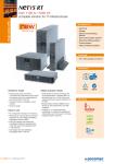
PRODUCT MANUAL
MANUEL DU PRODUIT
MANUALE DI PRODOTTO
PRODUKT HANDBUCH
MANUAL DE PRODUCTO
UNINTERRUPTIBLE POWER SUPPLY (UPS)
ALIMENTATION SANS INTERRUPTION (ASI)
SISTEMA DI CONTINUITÀ (UPS)
UNTERBRECHUNGSFREIE STROMVERSORGUNG (USV)
SISTEMA DE ALIMENTACIÓN ININTERRUMPIDA (SAI)
2DK00R00.doc
NeTYS 1000÷3000 VA Product Manual
NeTYS PR
1000÷3000 VA
PRODUCT MANUAL
CONTENTS
1.
SAFETY STANDARDS ...............................................................................................................4
2.
GENERAL DESCRIPTION.......................................................................................................... 5
2.1.
LED-BASED CONTROL AND DISPLAY PANEL ................................................................ 6
3.
UNPACKING AND INSTALLATION ........................................................................................... 7
3.1.
UNPACKING........................................................................................................................ 7
3.2.
ENVIRONMENTAL REQUIREMENTS FOR INSTALLATION ............................................. 7
3.3.
CONNECTION TO THE MAINS POWER SUPPLY AND CONNECTING THE LOAD........ 8
4.
CONFIGURATION AND START-UP .......................................................................................... 9
5.
OPERATING MODES ................................................................................................................. 10
6.
COMMUNICATION ..................................................................................................................... 11
7.
MAINTENANCE .......................................................................................................................... 12
7.1.
REMEDIES FOR MINOR PROBLEMS................................................................................ 12
8.
TECHNICAL DATA ..................................................................................................................... 13
2DK00R00.doc
NeTYS 1000÷3000 VA Product Manual
SAFETY STANDARDS
CERTIFICATE AND CONDITIONS OF WARRANTY
This SOCOMEC SICON UPS uninterruptible power system is guaranteed against manufacturing
and material defects, for a period of 24 months from the date of purchase and not however more
than 27 months from the date of shipment by SOCOMEC SICON UPS..
The warranty is of the 'carry-in' type: free supply of parts and labour for repairs, with return of a product
to be replaced to SOCOMEC SICON UPS, or authorized centres, at the customer’s cost and risk.
In order to use the warranty service, the user must respect the following rules:
• the product must be returned exclusively in its original packaging. Any damage caused during
shipping in packaging other than the original is not covered by the warranty;
•
the product must be accompanied by proof of purchase: a document (bill, invoice, receipt) showing
the date of purchase and the information necessary to identify the product (model, serial number).
The number of the authorization for return for repairs must also be attached, with a detailed
description of the defect found in the product. If any of these elements is missing, the warranty is
invalid. The return authorization number is issued by the service centres by telephone on receiving
notification of the malfunction;
The warranty is recognised within Italian territory. If the UPS is exported outside Italian territory, the
warranty shall be limited to the cover of the parts used to repair the fault.
.
The warranty shall not apply in the following cases:
• Failures due to fortuitous circumstances or force majeure (lightning, floods, etc.);
• Failures due to negligence or improper use (use outside tolerance limits: temperature,
humidity, ventilation, electric power supply, applied load, batteries);
• Insufficient or inadequate maintenance;
• Attempted maintenance, repairs or modifications not carried out by SOCOMEC SICON UPS
personnel or personnel from a support centre authorised by SOCOMEC SICON UPS.
• If the battery has not been recharged in accordance with the terms indicated on the packaging
and in the manual, in cases of extended storage or UPS inactivity.
SOCOMEC SICON UPS may, at its own discretion, opt for the repair of the product or for the
replacement of the faulty or defective parts with new parts or with used parts that are equivalent to
new parts with regard to functions and performance.
Defective or faulty parts replaced free of charge are to be put at the disposal of SOCOMEC SICON
UPS that becomes the sole owner.
Replacements or repairs of parts and any modifications to the product during the warranty period shall
not extend the duration of the warranty.
In no case will SOCOMEC SICON UPS be responsible for damages (including, without limitations,
damage for loss of earnings, interruption of activity, loss of information or other economic losses)
deriving from the use of the product.
The present conditions are subject to Italian law. Any dispute falls under the province of the Court of
Vicenza.
* For further information: www.socomec-sicon.com
SECTION 1 Q
3
8DK00R00.doc
NeTYS PR 1000 VA
4
3
1
7
6
NeTYS PR 1500-2000 VA
3
IN
SNMP
OUT
2
BREAKER 250VAC/13A
4
10A MAX
COM.PORT
OUTPUT
INPUT 10A MAX
TO/FROM EXTERNAL BATTERY
INPUT :48VDC 50A(NOM)
PUSH TO RESET
TO/FROM EXTERNAL BATTERY
INPUT :48VDC 50A(NOM)
EPO
7
8
5
6
1
NeTYS PR 3000 VA
Rear view
2
6
7
1
4
4
!
VIEW SECTION
8
5
6
3
8DK00R00.doc
GB
1 Fan / air vents
2 Slot for optional communication boards
3 NTP protections (RJ45)
4 RS232/USB serial port
5 Battery connection for extension
6 UPS output sockets
7 Input socket and fuse
8 EPO emergency Power Off
I
1 Ventilatore / griglia di ventilazione
2 Slot per schede di comunicazione opzionali
3 Protezione NTP (RJ45)
4 Connettore seriale RS232/USB
5 Connettore batteria per espansione esterna
6 Presa di uscita UPS
7 Presa ingresso rete e fusibile
8 EPO emergency Power Off
F
1 Ventilateur / prises d’air
2 Cache pour cartes de communication optionnelles
3 Protection NTP (RJ45)
4 Connecteur série RS232/USB
5 Connecteur batterie pour extension externe
6 Prise de sortie (ASI)
7 Prise arrivée réseau et fusible
8 EPO emergency Power Off
D
1 Lüfter / Belüftungsanlage
2 Abdeckung für Kommunikationskarten (Option)
3 Sicherung NTP (RJ45)
4 Serieller Anschluß RS232/USB
5 Batterieanschluß für eine externe Erweiterung
6 Ausgang zur Last (USV)
7 Netzeingang und Sicherung
8 EPO emergency Power Off
E
1 Ventilador / tomas de aire
2 Slot para tarjetas de comunicación opcionales
3 Protección NTP (RJ45)
4 Conector serie RS232/USB
5 Conector de batería para expansión externa
6 Toma de salida (SAI)
7 Toma de entrada red y fusible
8 EPO emergency Power Off
VIEW SECTION !
5
8DK00R00.doc
NeTYS PR 1500-2000 VA
migration from Tower to Rack 19’’
!
"
#
$
%
&
'
Front and rear brakets for
Rack assembling mode.
(
6
!
VIEW SECTION
8DK00R00.doc
NeTYS PR 3000 VA
migration from Tower to Rack 19’’
Optionals rails
Rack fixing accesories
VIEW SECTION !
7
2DK00R00.doc
NeTYS 1000÷3000 VA Product Manual
SAFETY STANDARDS
1. SAFETY STANDARDS
This manual must be kept next to the UPS, so that the operator may consult it at any time for clarification on the
correct use of the UPS.
Read the manual carefully before connecting the unit to the mains power supply and to the devices to be powered.
Before switching on the UPS (Uninterruptible Power Supply), the operator must be fully aware of the functions and
positions of all the controls and of the technical and functional characteristics of the system, in order to avoid any risk
to persons and to the equipment.
• Before starting, the unit must have an equipotential connection as established by the safety standards in force.
The earth cable of the UPS must be connected to an efficient earth point.
• If the unit is not earthed, all devices connected to the UPS will not have an equipotential connection. In this
case the manufacturer declines all responsibility for damage or accidents caused by non-observance of the
aforementioned standards.
•
This is pluggable type A equipment with battery already installed by the supplier, it’s operator installable and
may be operated by layman.
•
In case of power failure (UPS in back up mode), do not disconnect the input cable from the mains so as to
ensure earth connection to the powered loads.
• All subsequent maintenance operations must be carried out solely and exclusively by authorized personnel.
Inside the system high electric voltages are generated which may endanger maintenance personnel who are
not sufficiently prepared and trained for such tasks.
• If at any time a hazard condition is created during use, disconnect the mains power supply (if possible through
the control panel upstream of the unit) and shutdown the UPS completely following the appropriate procedure.
• When assembling and replacing the battery, the UPS should always be switched off and disconnected from the
mains power supply. Do not dispose of batteries in a fire, the battery may explode.
• CAUTION : a battery can present a risk of electric shock and high short circuit current. The following precaution
should be observed when working on batteries: remove watches, rings or other metal objects and use tools with
insulated handles.
• The batteries constitute an internal power source for the UPS and mean that the system output may be
powered even when the UPS is not connected to the mains power supply.
• Do not force, break or try to open the batteries. They are sealed and do not require any maintenance. They
contain substances that are toxic to health and that pollute the atmosphere. Do not switch the UPS on if any
leakage of liquid or white powder residue is noted.
•
Replace batteries with the same number and type of batteries as originally installed in the equipment.
•
Replace the fuses ONLY with other fuses of the same type.
•
As the mains cable of the UPS is considered a disconnecting device, the mains socket to which the UPS is
connected and/or the rear of the UPS must be accessible and easy to disconnect.
Avoid contact of the UPS unit with water or liquids in general. Do not introduce foreign bodies.
If the unit needs to be scrapped, it must be handed over solely and exclusively to specialist disposal
companies. These companies are obliged to break up and dispose of the various components in accordance
with the national legal provisions in force.
The UPS generates a leakage current of about 1.5mA. To guarantee the maximum limit leakage current of
3.5mA, make sure that the maximum leakage current of the load is 2 mA. If the load current exceeds this value,
have qualified personnel connect the UPS to an industrial type, IEC 309 compliant power supply mains, with a
current of correct dimensions for the UPS power rating.
NeTYS UPS is intended for commercial and industrial use; it is not recommended for use in medical
applications that are essential to the survival of the patient.
•
•
•
•
•
4
Use the UPS in accordance with the technical specifications given in the User Manual.
Q SECTION 1
2DK00R00.doc
GENERAL DESCRIPTION
NeTYS 1000÷3000 VA Product Manual
2. GENERAL DESCRIPTION
NeTYS: sure power supply for PC, servers, graphics stations and network devices.
The main purpose of the UPS is to protect sensitive and critical equipment from electrical disturbances that can
compromise operation. Black-outs, brown-outs, variations in voltage and frequency, lightning, electrostatic
discharges and rapid over voltages are phenomena found in all office and industrial environments and which cause
damage to the hardware and loss of data.
NeTYS is an Uninterruptible Power Supply designed to power computers and connected peripherals, with the
exception of any other electrical device (such as household appliances, television sets, stereo systems and video
recorders).
INTRODUCTION
The characteristic feature of these UPS is the constant monitoring of the power supply which, duly filtered and
stabilised (on models with AVR) and if considered suitable, is used to supply consumers. In cases of a mains failure
or if the mains is considered to be outside limits accepted by the load, the inverter (the heart of the UPS) is activated
immediately. Drawing on the power stored in the batteries, the inverter generates a voltage that instantly takes over
from the mains without any disruption to the equipment connected.
During operation under emergency conditions, the internal batteries discharge but are recharged again automatically
when mains power returns.
Being hermetically sealed, the batteries do not require maintenance of any kind at any stage of their working life.
Block diagram
The block diagram provides a useful aid to understanding how the machine operates.
1
2
3
Legend
1
2
3
4
5
6
7
Mains input
Battery-charger
Automatic Voltage stabilizer (AVR models only)
Inverter (DC/AC)
Automatic transfer switch
Batteries for back-up extensions (optional)
Output to power consumers
4
5
6
7
SECTION 1 Q
5
2DK00R00.doc
NeTYS 1000÷3000 VA Product Manual
2.1.
GENERAL DESCRIPTION
LED-BASED CONTROL AND DISPLAY PANEL
ON/OFF button (press for 3 seconds)
Buzzer silence & self test mode button
Configuration mode button
Button to confirm
Visual indication of operating mode
LED green (1) lit = NORMAL MODE (mains ok)
flashing = NORMAL MODE (AVR active)
LED yellow (2) flashing = BATTERY MODE (mains absent or abnormal)
flashing fast = battery low
LED
(red) flashing = alarm present; lit = fault
LED
(yellow) flashing = overload
LED
(yellow) flashing = wide range input mode
LED
(red) flashing = battery disconnected; lit = battery needs replacing
Battery LED bar (capacity %) 25% steps
Load LED bar (power %) 25% steps
Detailed alarm indication = LED
flashing +:
25% battery LED bar flashing = Fan fault
Detailed failure indication = LED
lit +:
25% of battery LED bar flashing = Fan failure
50% of battery bar LED flashing = Overtemperature stop
All LEDs on battery bar flashing = Shortcircuit
75% of battery bar LED flashing = Output voltage abnormal
100% of battery LED bar flashing = abnormal battery recharge
Acoustic alarms
Intermittent alarm every 4 seconds = BATTERY MODE
Intermittent alarm every second = battery low
LED is flashing
Intermittent alarm every second = overload if
Continuous alarm = UPS failure (see detailed failure indication)
6
Q SECTION 1
2DK00R00.doc
NeTYS 1000÷3000 VA Product Manual
UNPACKING AND INSTALLATION
3. UNPACKING AND INSTALLATION
3.1.
UNPACKING
Remove the UPS and all the accessories that come with it (cables, CD-ROMs, etc) from its packing case.
It is always advisable to keep the original packaging that has been specially designed for safe transport, in case the
unit has to be moved again.
3.2.
ENVIRONMENTAL REQUIREMENTS FOR INSTALLATION
Install the UPS after first checking the following:
NeTYS has been designed for use in closed environments.
Place the UPS on a flat and stable surface, in a ventilated environment away from heat sources and exposure to
direct sunlight.
Keep ambient temperature between 0°C and 40°C and humidity less than 90% (non-condensing); the best
temperature to guarantee longest possible battery life is 15-20°C.
Ensure that the environment where the UPS will be installed is not dusty, and leave a space of at least 20 cm
around it to allow for adequate ventilation and access to the rear panel.
Make sure not to place the UPS or any other heavy object on the cables.
Check that the voltage and frequency preset for operation is right for your electrical power supply looking the
data can be found on the data plate.
Use only the manufacturer-supplied or recommended cables and accessories for connections to the
RS232/USB serial interface
The lateral brackets supplied must be mounted on models designed for installation in standard 19” cabinets.
It is recommended that the batteries be left to charge for 8 hours the first time the unit is used.
SECTION 1 Q
7
2DK00R00.doc
NeTYS 1000÷3000 VA Product Manual
3.3.
UNPACKING AND
INSTALLATION
CONNECTION TO THE MAINS POWER SUPPLY AND CONNECTING THE LOAD
Cables with the appropriate cross-section and conforming to the safety standards in force should be used for
connection to the mains and connection of the loads.
1500/2000VA model only: connect the UPS power cord
to the mains power supply.
Connect the UPS power cord to the mains power supply
The mains input may be connected using the cable that previously powered the server.
Connect the loads to the outlet sockets on the rear of the UPS.
Use the two IEC320 cables supplied for the output connections.
Use of the battery expansions (optional on models 1500/2000/3000 PR)
Back-up extension units are available on some models when long-life battery operation is required. By combining
the UPS with one or maximum two battery expansion units, back-up times of up to 60 minutes may be obtained.
!
Danger
Make sure that the safety switch on the battery expansion unit is in
the “OFF” position during the connection procedure.
Place the battery expansion unit beside the UPS on the side with
no air vents. Connect the battery expansion unit to the UPS using
the special cable supplied.
Once connection has been completed, configure the back-up
expansion unit using the special menu as described in chapter 4.
SWITCHING THE UPS ON
Switch the UPS on by pressing the ON button on the front panel. The “Normal mode” LED will light up: allow ten
seconds for the self-teach procedures to run.
When you are sure that the UPS is functioning properly, the various loads may be switched on and work may
commence in protected mode.
SWITCHING THE UPS OFF
Warning! This UPS has been designed to control and maintain the battery charge; therefore only in
exceptional circumstances are you advised to switch it off completely
To shutdown the UPS completely, press and hold down the OFF button and take out or disconnect the mains power
supply.
The UPS switches off all the LEDs and is then fully deactivated. If the mains cable is not disconnected, the batterycharger remains active.
8
Q SECTION 1
2DK00R00.doc
NeTYS 1000÷3000 VA Product Manual
CONFIGURATION AND START-UP
4. CONFIGURATION AND START-UP
CONFIGURATION OF THE OUTPUT VOLTAGE/BATTERY EXPANSION UNITS
L
WARNING
The factory default configuration for the NeTYS PR model is for operation with an output
voltage of 230V, without any additional battery expansion units.
No configuration is required for normal use with standard back-up.
Parameter settings:
- Input mode (normal 184÷276V /wide range
- Output voltage (220/230/240 V)
- Battery expansion units (0-1-2)
160÷276V)
are configured using free UPS communication software that can be downloaded from:
www.socomec-sicon.com.
If wide range has been configured the yellow LED
will come flashing.
Configuration from mimic panel
Output voltage and Battery expansion parameters are also settable by mimic panel following the below procedure:
Output voltage configuration
menu
push
3 seconds to start the procedure.
First is current setting 230 V led flashing
240 V
230 V
220 V
push again
second is 240 V flashing
push again
third is 220 V flashing
push 3 seconds to confirm,at
the same time, change to Battery
extentions configuration menu.
After Output voltage configuration
Battery expansion
configuration menu
push
First is 0 expansion (only UPS) led
flashing
2 battery expansion
1 battery expansion
0 =no battery expansion
push
second is 1 expansion led flashing
push
third is 2 expansion led flashing
push 3 seconds to confirm
configuration and exit.
SECTION 1 Q
9
2DK00R00.doc
NeTYS 1000÷3000 VA Product Manual
OPERATING MODES
5. OPERATING MODES
NORMAL MODE
When mains power is available and the voltage falls within the acceptable range, the NORMAL MODE LED on the front
panel remains on permanently. In this mode, the loads are powered from the mains power supply either directly or
through the AVR stabiliser which intervenes in cases of voltage peaks. The batteries are constantly recharged.
BATTERY MODE
The UPS switches automatically to this operating mode when mains power fails (spikes or lengthy black-outs) or if
the mains is at a value considered to be dangerous; the consumers are powered using the energy stored in the
batteries converted to AC voltage through the inverter.
In this mode, a slow intermittent acoustic alarm sounds, while the BATTERY MODE LED on the front panel flashes.
In cases of prolonged mains failure, the UPS powers the consumers until it shuts down when the batteries are fully
depleted (see the chapter on COMMUNICATION for orderly shutdown via software).
Just before shutdown when the battery charge runs out fully, low battery charge is signalled via a rapid intermittent
acoustic alarm.
The UPS automatically returns to normal operating mode about two seconds after the mains power is restored. The
time taken to transfer from normal to battery mode and vice-versa is imperceptible to the load.
OVERLOAD
The UPS can power loads up to the power rating declared on the machine’s data plate; once this limit is exceeded,
the machine goes into overload condition.
Overloads are signalled by a rapid sounding acoustic alarm .
Warning: Significant overloads could cause permanent damage to the UPS!
Avoid connecting laser printers that generate absorption peaks liable to cause overloads on the UPS.
SELF TEST
button is pressed for more than five seconds, a procedure is run to check battery
In NORMAL MODE, when the
and inverter operation.
If everything is working properly, the UPS automatically returns to NORMAL MODE; if not the test is suspended and the
battery failure is reported through the Battery failure LED
. If the test fails, however, it is recommended that you
leave the battery to charge overnight and repeat the test the next day.
It is advisable to perform the test with the batteries fully charged (LED bar fully lit up).
10 Q SECTION 1
2DK00R00.doc
NeTYS 1000÷3000 VA Product Manual
COMMUNICATION
6. COMMUNICATION
The UPS provides excellent protection against interruptions or imperfections in the mains power supply. In these
cases the computer (load) is powered by the UPS using battery power until this runs out.
Various software applications and communication options are available to optimise operation of the UPS and to
correctly manage shutdown when back-up power ends. The status of the UPS can be monitored, keeping track of all
the mains failures and battery discharges so as to activate an automatic and orderly procedure to close the
programs and shutdown the system. When mains power returns the system will restart automatically.
All NeTYS models are equipped with RS232 and USB communication interface (USB not available on the NeTYS
PR 1000 model).
COMMUNICATION SOLUTIONS
Depending on the model, there are different types of connections and software compatibility as shown in the table
below:
Uni Vision local management software for local shutdown of Windows™ & Linux systems.
Free on http://www.socomec.fr/page_uk/lien_prod_ups.htm
RS232
Uni Vision Pro network management software for local and remote shutdown: supports
the major operating systems through Java Shutdown Client technology.
RS232
HID: UPS management based on Windows™ embedded service
NetVision Web/SNMP manager for UPS control over LAN with TCP/IP protocol. Allows
remote shutdown through Java Shutdown Client technology.
BMS: possibility to integrate the UPS with BMS (Building Management Systems)
USB
Web/SNMP
card
JBUS
protocol
RS232 INTERFACE
Communication with the server can take place directly via the RS232 interface.
In addition to local or networked shutdown it is possible to perform full monitoring of the electrical parameters
regarding battery status and the automatic programming of the UPS start-up and shutdown procedures.
For a complete description of the software features, refer to the Uni Vision and Uni Vision Pro documentation.
USB INTERFACE
In addition to the RS232 serial link, it is also possible to establish communication directly through USB with the HID
protocol, when this is available in the operating system.
In this case, no SW needs to be installed. A standard USB cable is used and once this is connected, it is recognised
just as any normal peripheral.
The control parameters of the unit can be set directly via the operating system service menu.
Net Vision card x slot
Net Vision permits direct connection of the UPS to a LAN (RJ45 Ethernet) and remote control of the UPS through
TCP/IP using a WEB browser. For a complete description, refer to the Net Vision documentation.
SECTION 1 Q
11
2DK00R00.doc
NeTYS 1000÷3000 VA Product Manual
MAINTENANCE
7. MAINTENANCE
7.1.
REMEDIES FOR MINOR PROBLEMS
This section examines some of most likely problems that can compromise correct operation of the UPS, attempting
to solve them and identifying the possible causes and remedies.
!
THE UPS INTERNALLY GENERATES HAZARDOUS ELECTRICAL VOLTAGES. ALL MAINTENANCE
MUST BE PERFORMED SOLELY AND EXCLUSIVELY BY AUTHORIZED PERSONNEL.
If you have difficulty in getting the UPS to work, the reason may be among those listed below. For any other
problem, you are advised to get in touch with your dealer or service organisation directly. For quick and effective
action, when you call it is important to give precise details of the defect, the model number and the manufacturing
serial number that can be found on the conformance and inspection certificate or on the data plate on the bottom of
the UPS.
PROBLEM
CAUSE
The UPS works in battery mode even if - Poor connection to the input
mains power is available
mains.
Back-up time shorter than expected
The UPS stalls/goes into overload
alarm
SOLUTION
-Check the connection of the cable
to the UPS and to the mains outlet.
-The mains voltage is
out of range
-No solution because mode of
operation is correct.
-Input protection triggered
(blown fuse or automatic
switch)
-Replace the input fuse with another
of the same type or reset the
automatic switch.
-Batteries not fully charged.
-Leave the batteries to charge for 8
hours consecutively.
-Batteries not working
properly.
-Have the batteries replaced by
authorised personnel.
Overload on the load line.
Check that the load applied is not
greater than the maximum permitted
or reduce the load power
requirement.
IF THE EQUIPMENT IS TO BE LEFT IDLE FOR A LONG PERIOD, WAIT FOR THE BATTERIES TO CHARGE FULLY
BEFORE SWITCHING OFF. WHILE THE UPS IS LEFT IDLE, MAKE SURE THAT THE BATTERIES ARE RECHARGED FOR
24 HOURS AT LEAST ONCE EVERY 4 WEEKS.
12 Q SECTION 1
2DK00R00.doc
TECHNICAL DATA
NeTYS 1000÷3000 VA Product Manual
8. TECHNICAL DATA
NeTYS PR
Power
INPUT
Voltage
Frequency
Mains connection
Spike protection
IEC 61000-4-5
OUTPUT
Voltage
(in Normal Mode with AVR)
Voltage
(in Battery Mode)
Frequency
Wave form
Transfer time
Normal Mode protections
Battery Mode protections
Load connection socket
IEC 320
BATTERY
Typical back-up time
Battery recharge
COMMUNICATION
Communication interface
Ethernet adapter
Local communication software
Local and remote communication
software
Data line protection
ENVIRONMENT
Noise level (normal mode)
Temperature
Environment
Reference standards
WEIGHT AND DIMENSIONS
Dimensions (WxDxH mm)
Dimensions (WxDxH mm) 2U, RM
Net weight
1000 MT
1000VA (700W)
1500 MT
2000 MT
3000 RT
1500VA (1000W) 2000VA (1340W) 3000VA (2100W)
160* - 276 V (230V nominal)
50 / 60 Hz with automatic selection
IEC320 (10A)
300V, 230j / 6500 A
IEC320 (16A)
300V, 460j / 6500 A
The AVR increases (boost 1) the output voltage by 15% when the input
voltage drops below 90% of the nominal value,
The AVR decreases (bucks) the output voltage by 12% when the input
voltage rises above 110% of the nominal value.
230V ± 5% (-10% after battery low)
50 / 60 Hz
Sinusoidal
2-4 milliseconds (typical)
overload (110% for 3 minutes); shortcircuit protected
overload (110% for 30 seconds); shortcircuit protected
# 8 (10A)
# 6 (10A)
# 1 (16A)
8 min.
8 min.
8 min.
8 min.
4 hours 80% Cn (after full discharge)
Under permanent charge even when the UPS is off (mains present)
RS232 / USB**
NET-VISION (TCP/IP & SNMP) optional card**
UPS Management software – Windows™ & Linux
(free download)
Optional UNI VISION PRO CD
Windows™, AIX4.3/5.1, HP-UX10.20/11, Solaris 8/9, GNU/Linux,
Novell.5/6
NTP data line suppressor: RJ45 10 Base T
< 45 dBA (at 1 meter)
0- 40°C
(10- 25°C for optimum battery life)
Altitude: 2000 mt, humidity: 95% non-condensing
(EN) IEC62040-1-1 (safety), EN50091-2/IEC 62040-2 (EMC),
EN 61000-4-5/C62.41:1991 (surge)
87 x 385 x 235
9,6 Kg
2 x ( 87x 415 x 220)
435 x 415 x 87
18 Kg
19 Kg
87 x 585 x 440
440 x 585 x 87
31,5 Kg
* selecting wide mode.
** 1500/2000/3000 models
SECTION 1 Q
13
Socomec Sicon UPS
worldwide:
IN E U R O P E
IN ASIA
BELGIUM
Schaatsstraat, 30 rue de Patinage
B - 1190 Bruxelles
Tel. +32 (0)2 340 02 34 - Fax +32 (0)2 346 16 69
[email protected]
FRANCE
95, rue Pierre Grange
- 94132 Fontenay-sous-Bois Cedex
Tel. +33 (0)1 45 14 63 90 - Fax +33 (0)1 48 77 31 12
[email protected]
GERMANY
Heppenheimerstraße 57
D - 68309 Mannheim
Tel. +49 (0) 621 7168 40 - Fax +49 (0) 621 7168 444
[email protected]
ITALY
Viale Tolstoi, 73 - Zivido
20098 San Giuliano Milanese (MI)
Tel. +39 02 98 242 942 - Fax +39 02 98 240 723
[email protected]
NETHERLANDS
Bergveste 2F
NL - 3992De Houten
Tel. +31 (0)30 63 71 504 - Fax +31 (0)30 63 72 166
[email protected]
SLOVENIA
Savlje 89
SI - 1000 Ljubljana
Tel. +386 1 5807 860 - Fax +386 1 5611 173
[email protected]
SPAIN
C/Nord, 22 Pol. Ind. Buvisa
- 08329 Teià (Barcelona)
Tel. +34 93540 7575 - Fax +34 93540 7576
[email protected]
UNITED KINGDOM
Units 401/402
Cirencester Business Park
Love Lane
Cirencester
Gloucestershire
GL7 1YG
Tel. +44 1285 644 444 - Fax +44 1285 644 414
[email protected]
INDIA
Atma Ram Mansion
1/21 Asaf Ali Road
IN - New Dehli - 110 002
Tel. +91 11 23234411 - Fax +91 1123232639
[email protected]
SINGAPORE
25 Tagore Lane, # 01-02
Singapore Godown
SG - 787 602 Singapore
Tel. +65 6 554-0900 - Fax +65 6 458-7377
[email protected]
THAILAND
17/178 Prachachuen Road
Tungsonghong, Laksi
TH - 10210 Bangkok
Tel. +66 2 503 92 43 - Fax +66 2 503 99 23
[email protected]
HEAD OFFICE
SOCOMEC GROUP SWITCHING PROTECTION AND UPS
S.A. capital 10 923 800 € - R.C. Strasbourg 548500 149 B
SOCOMEC SICON UPS Strasbourg
11, route de Strasbourg - B.P. 50 - F-67230 Huttenheim FRANCE
Tel. +33 (0)3 88 57 45 45 - Fax +33 (0)3 88 74 07 90
[email protected]
SOCOMEC SICON UPS Vicenza
Via della Tecnica, 1 - I - 36030 Villaverla - ITALIA
Tel. +39 0445 359 111 - Fax +39 0445 359 222
[email protected]
SALES AND MARKETING
MANAGEMENT
SOCOMEC SICON UPS Paris
95, rue Pierre Grange
F-94132 Fontenay-sous-Bois Cedex - FRANCE
Tel. +33 (0)1 45 14 63 90
Fax +33 (0)1 48 77 31 12
[email protected]
www.socomec-sicon.com