1
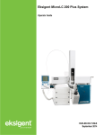
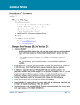
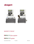
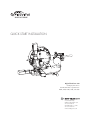
QUICK START INSTALLATION
Digital PicoView® 450
Nanospray Ion Source
For AB SCIEX Mass Spectrometers
4000, 4500, 4600, 5500, and 5600
2 Constitution Way
Woburn, MA 01801 USA
781 933 9560 Tel
888 220 2998 U.S. Sales
781 933 9564 Fax
www.newobjective.com
DPV-450 QUICK START INSTALLATION
Read This First
Safety Considerations
WARNING: Electrospray ionization involves the use of potentially lethal high-voltage electrical current. Observe all
manufacturers’ safety recommendations in the use of such equipment. No equipment modifications should be made
except by trained personnel using methods approved by the manufacturer in accordance with all safety requirements.
Installation of equipment should be performed by qualified personnel in accordance with all applicable electrical
codes.
Never use this product with defective, damaged, or faulty equipment. Serious injury or death could result.
SAFETY PRECAUTIONS: Only qualified personnel should use this product. Provide a safe workplace equipped with
all necessary safety equipment.
Prior to Installation
Follow all safety recommendations of the equipment manufacturer(s). All system voltages must be brought to ground
potential and all high-voltage contacts disconnected from the inlet system before installation of the PicoView®
system.
Inspect all equipment carefully prior to use. Any damaged, chipped, or cracked components should not be used and
must be discarded or repaired.
Handling Fused-Silica Tubing
Handling of fused-silica or glass tubing and tips can result in serious personal injury, including eye and skin injury.
Use safety glasses or goggles meeting ANSI Z87.1-1989 requirements, or the equivalent. Puncture- and chemicalresistant gloves should also be worn at all times.
Tip Adjustment and/or Replacement
Do not attempt to adjust or replace the tip unless the ESI high voltage and other applicable voltages are turned off
and are at ground potential.
Reduce any applicable backing pressure (liquid, gas, etc.) to ambient before loosening ESI tip fittings and removing
the fused-silica tip or transfer line from the coupling union. Prior to pressurization, make sure that components
are tightened to specifications to prevent separation during use. Failure to adhere to this warning could result in
projectile-like expulsion of the tip from the coupling union, which could cause serious personal injury or damage to
surrounding apparatus.
The Transfer Line
The transfer line connecting to either a tip module or the Micro Injection Valve must not be made from an electrically
conductive material. It must be fabricated from an electrically insulating material such as PEEK™ or fused silica.
Otherwise, the operator may be exposed to potentially lethal voltage.
In systems where high voltage is applied directly to the ESI tip, the liquid sample inside the tip and transfer line
tubing is also raised to a high voltage. To prevent exposure to potentially lethal voltages, a suitable ground point for
the liquid inside the line must be provided.
WARNING: Do not defeat any mass spectrometer system software or hardware safety interlocks.
DPV-450 QUICK START INSTALLATION
Trademarks
The following trademarks are found in this instruction guide: Teflon is a registered trademark of E.I. du Pont de
Nemours and Co.; QTrap, TripleTOF, Eksigent and Analyst are trademarks or registered trademarks of AB SCIEX
Pte. Ltd. or their respective owners; MicroTight and SealTight are trademarks or registered trademarks of Upchurch
Scientific, Inc. a division of IDEX Corporation; PEEK is a trademark of Victrex plc; Windows is a registered trademark
of Microsoft Corporation; PicoView, Digital PicoView, PicoClear, PicoTip, PicoFrit, SilicaTip, TaperTip, GlassTip,
and PicoTip Powered are trademarks or registered trademarks of New Objective, Inc. All other trademarks are the
properties of their respective companies.
Limited Warranty
DISCLAIMER
Technical information contained in this publication is for reference purposes only and is subject to change without
notice. The information is believed to be reliable and accurate; however, nothing set forth herein constitutes a
warranty of any kind or nature. Given the variety of experimental conditions, New Objective, Inc., cannot guarantee
performance at a given flow rate; the best guide to tip selection and operation is empirical testing.
The user is solely responsible for complying with any patent(s) pertaining to applications or methods using the
products described or mentioned in this manual.
New Objective, Inc., warrants this Product (Digital PicoView®) to be free of defects in materials and workmanship
for a period of one (1) year from the date of shipment. Any item believed to be defective within the meaning of the
foregoing sentence shall be returned to New Objective, Inc., and, if found by us to be defective, shall be repaired or
replaced with conforming Product of like kind. Please note that a Return Merchandise Authorization Number (RMA)
will be required. New Objective, Inc., will pay return freight on unsatisfactory items. New Objective, Inc., shall have
no other liability or obligation with respect to goods alleged to be defective. The foregoing shall constitute the sole
and exclusive remedy, and New Objective, Inc.’s total liability for any and all losses and damages arising out of any
cause whatsoever (whether such cause be based in contract, negligence, strict liability, other tort, or otherwise) shall
in no event exceed the purchase price of the Product(s) in respect of which the cause rose. New Objective, Inc.,
disclaims, and shall not be liable, in any event, for loss of profits, consequential or incidental damages, or punitive or
exemplary damages in connection with the Product furnished hereunder.
The foregoing limited warranty (i) shall be void as to any item of Product which is in any material respect altered by
the user; (ii) does not cover misuse of the Product (for example, but not limited to, dropping or other mishandling of
any components of PicoView, improper trimming of SilicaTips™, PicoFrit® Columns, or TaperTips™, damage caused
by application of or exposure to excessive temperature, pressure, or voltage) or SilicaTip, PicoFrit, or TaperTip failure
by reason of clogging; and (iii) does not cover standard consumable items supplied with PicoView such as, but not
limited to, microtees, unions, tubing sleeves, fittings, etc.
The digital camera is also warranted to be free from defects in material or workmanship for a period of one (1) year
from the date of purchase.
DPV-450 QUICK START INSTALLATION
Overview of Components
17
1.
2.
3.
4.
5.
6.
7.
8.
9.
10.
11.
12.
13.
14.
1
19
18
14
15
2
16
3
21
21
4
11
High-Contrast Curtain Plate
Rinsing Station
Safety Shield
Camera Mounting Ring
Digital Camera
Camera USB Cable
Base Plate
Magnetic Stage Plate
Lock Bolt
Mounting Rails
XYZ Stage
Actuator Y
Actuator X
Fiber Optic Cable
20
13
8
6
5
7
10
15.
16.
17.
18.
19.
20.
21.
10
12
9
Illuminator
Illuminator Mount
Actuator Z
Voltage Module
Sheath Gas Module
Rinse Basin
Locking Levers
Voltage Module Configurations
Sheath Gas Tee
SilicaTip or
TaperTip
PicoFrit Column
Cover
Microtee
Steel Union
Locking Screw
To Autosampler
or LC
To LC Column
HV Connection
Voltage Module
Setup for use with standard microtee
(P/N MICT-PV is shipped in the accessories kit)
Shown with cover removed
Setup for use with standard steel union
(P/N C360US62PKG-NO is shipped in the
accessories kit) Shown with cover removed
DPV-450 QUICK START INSTALLATION
The process for problem-free installation of the DPV-450 follows. For detailed information, please refer to the
complete user manual.
Section 1: Hardware Installation
STEP 1
Prepare instrument for DPV-450 istallation by removing standard
curtain plate from the nanospray interface
STEP 2
Install high-contrast DPV-450 curtain plate onto nanospray interface
STEP 3
Install DPV-450 source ring onto nanospray interface. Align mounting
pins on instrument with recessed features on DPV-450 and press
source ring flush against instrument panel.
STEP 4
Rotate locking levers 180° (down) to lock source ring onto interface
DPV-450 QUICK START INSTALLATION
STEP 5
Remove blue tape to release nebulization gas tubing
Note: Tubing may be taped or twist-tied.
STEP 6
Install DPV-450 source body onto rails and slide forward
DPV-450 positioned as far forward as possible
STEP 7
Install locking nut (found in the accessories box) into right-side rail. No
locking nut in the left rail is necessary.
STEP 8
Install stage actuation motors
Gently pull the XYZ stage towards center of source and insert motor
labeled “X” into the “X” stage port.
DPV-450 QUICK START INSTALLATION
Tighten set screw on stage port using a 2mm hex wrench (provided).
Repeat process for “Y” actuator, gently pushing the XYZ stage forward
to insert the actuator into the stage port. Tighten using the 2mm hex
wrench (provided).
Repeat process for “Z” actuator, gently lifting the XYZ stage up to insert
the actuator into the stage port. Tighten using the 2mm hex wrench
(provided).
STEP 9
B
Connect actuation motors. The order in which the motors are
connected to each other is very important.
Locate the actuator coupling cable, a 15’-long, split-end cable that
supplies power and transfers data to and from the motors.
A
Connect male cable on X-axis motor to female cable (A, above left)
that will connect to USB port of host PC (B, above left). DO NOT
connect to host PC at this time
DPV-450 QUICK START INSTALLATION
Connect female cable on X-axis motor to male cable on Y-axis motor
Connect female cable on Y-axis motor to male cable on Z-axis
motor. Note that the second coble on the Z-axis motor should be left
unconnected.
STEP 10
Install Visualization System
Locate lens tube in the accessories box. Screw the tube onto the
front of the digital camera and install camera into the mounting ring,
following orientation as shown.
Tighten set screw using 2.5mm hex wrench (provided) to secure
camera in place
Install USB camera cable into camera.
DO NOT connect cable to PC at this time.
Insert fiber optic coupler into the illuminator mount and tighten thumb
screw to secure.
DPV-450 QUICK START INSTALLATION
Connect fiber optic cable to adapter ring on illuminator and tighten set
screw
STEP 11
Plumbing Voltage Module
Remove lid by loosening thumb screw
Insert microtee (located in the accessories box) into recess in base, as
shown
Tighten nut to
secure emitter
Feed emitter through the front of the sheath gas tee DISTAL END FIRST.
Pull through. Tighten nut on sheath tee to secure emitter in place.
Plumb distal end of emitter and transfer line into microtee (or steel
union) and install lid. Refer to user manual for detailed information on
plumbing microtee and steel union.
Feed emitter through sleeve
in tee, distal end first
STEP 12
Slide stage away from the inlet and place plumbed voltage module
onto magnetic plate of the XYZ stage
DPV-450 QUICK START INSTALLATION
Connect tubing for nebulization gas into gas tee
Connect voltage cable to voltage module
Section 2: Software Installation
NOTE: Software from the Digital PicoView® Installation USB thumb drive should be installed and the host PC
rebooted prior to making the USB connections between the Digital PicoView camera, XYZ actuators, and host PC.
1.
Locate the Digital PicoView Software Installation USB thumb drive.
2.
Insert the USB thumb drive into an available USB 2.0 port on the host PC.
3.
Open the folder titled ‘CD Template DPV450 v2.0.4’ for 32-bit operating systems or ‘CD Template 64 bit
DPV450 v2.0.4’ for 64-bit operating systems.
4.
Launch CDStarter.exe
5.
Accept the dialog box by clicking YES. The start-up window appears.
6.
Click “1-USB to Serial Install” to install the USB-to-serial converter driver. Follow the default installation
instructions.
7.
Click “2-Camera Install” to install the camera drivers. Follow the default installation instructions.
8.
Click “3-PV Configure Install” to install the PV Configure application. Follow the default installation instructions.
9.
Click “4-PV Acquire Install” to install the PV Acquire application and National Instruments™ Run-Time Engine.
Follow the default installation instructions.
10. Restart/re-boot the host PC.
NOTE: The host PC must be rebooted to complete software installation. Do not connect the USB cables from Digital
PicoView hardware prior to rebooting, as this will cause software failure.
DPV-450 QUICK START INSTALLATION
11. Two Digital PicoView applications have been installed in the Windows® START menu: “Digital PicoView >
PV450 Acquire 2_0_4” and “Digital PicoView > PV Configure”.
12. Additional Installation Notes are available on the New Objective USB thumb drive, follow these directions
should the cdstarter.exe application fail to run.
Section 3: System Initialization
STEP 1
Connecting the USB cables
NOTE: Prior to using PV Acquire, the USB connections between the
host PC and Digital PicoView source need to be established. This will
be followed by the creation of a default configuration file using the PV
Configure application.
1. Connect the USB cable from the digital camera to the host PC.
Follow onscreen instructions to activate USB driver (if required).
2. Connect the USB cable from the USB-to-serial converter (XYZ
stage actuators) to the host PC. Connect the 5V power supply to
wall power outlet. Follow onscreen instructions to activate USB
driver (if required).
STEP 2
Setting a Port Assignment for USB-to-Serial Adapter
NOTE: The USB-to-serial adapter will be assigned a virtual COM port
number by the operating system. This number needs to be determined
and is used by the PV Configure application to establish a default
settings file for PV Acquire.
1. Open the Windows Device Manager. In Windows XP this is
typically found under: Start > Control Panel (classic view) >
System > Hardware Tab (See Figure)
2. Click on the Device Manager button
3. The Device Manager List will open. Click on Ports (COM & LPT).
Look for USB-to-Serial Com Port in the sub-list.
4. Note the COM port setting (e.g. COM3, COM4, etc.) that will be
seen in parenthesis (this assignment will be needed when running
PV Configure for the first time)
Creating a Configuration Settings File
1. Select PV Configure from the Windows START menu under the
Digital PicoView heading. A dialog box asking you to select the
proper COM port will pop up.
2. Select the COM port number from the pull down menu selection
as reported by the Device Manager.
3. The main PV Configure dialog window is now available
DPV-450 QUICK START INSTALLATION
Click Save to save the settings file. A standard dialog window will open. The file may be saved under any name,
to any user-selected directory.
Note the file location and file name. Click the OK button to save the file. The PV Configure window will close
automatically.
PV Acquire Start-up
NOTE: PV Acquire requires user input of the location of the Configuration File each time it is started.
4.
Choose PV Acquire from the Start menu under the Digital PicoView heading.
5.
A dialog window asking for the location and name of the Configuration File created in the previous section will
appear. Choose the File and click OK.
6.
A second dialog window will open asking if the XYZ stage requires a Home Stage operation. Select ‘Yes’.
Once the stage is fully initialized and PV Acquire has established communication with the XYZ stage motors, a
confirmation dialog window will appear.
7.
Click OK in the message box to begin using PV Acquire.
Refer to the DPV-450 User Manuals for complete instruction on use.
Rev. 29513
2 Constitution Way
Woburn, MA 01801 USA
781 933 9560 Tel
888 220 2998 U.S. Sales
781 933 9564 Fax
www.newobjective.com
DPV-450 QUICK START INSTALLATION