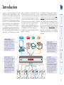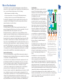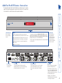
1
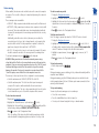
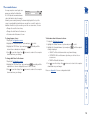
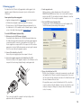
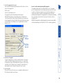
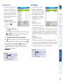
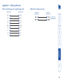
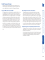
AdderView Pro 8 DVI User Guide COMPUTER KVM SPK USB1 USB2 PWR KB MS OSD UPG LCK MODE www.adder.com Configuration Configuration menus.................................................................11 Configuration menus layout.................................................11 General configuration................................................................12 Changing hotkeys..................................................................12 Choosing a default channel..................................................12 Editing the computer list.......................................................12 Autoscanning.........................................................................13 The reminder banner.............................................................14 Performing upgrades.............................................................15 Further information Getting assistance.......................................................................20 Appendix 1 – Configuration menus..........................................21 Functions................................................................................22 Global Preferences.................................................................23 Setup Options........................................................................24 Edit Computer List.................................................................25 EDID Options..........................................................................25 Appendix 2 – Cable specifications.............................................26 RS232 serial flash upgrade (null modem) cable...................26 Multi-head synchronisation cable.........................................26 Warranty.....................................................................................27 Safety information.....................................................................27 Radio Frequency Energy............................................................28 Index Mounting......................................................................................6 Connections..................................................................................7 User console.............................................................................7 Computer systems....................................................................9 Power in connection................................................................9 Multiple video head connections.........................................10 Installation Selecting a computer.................................................................17 To select a computer using the on-screen menu.................17 To select a computer using the front panel.........................18 To select a computer using the mouse buttons...................18 To select a computer using hotkeys......................................19 What is True Emulation?..............................................................3 AdderView Pro 8 DVI features - front and rear..........................4 What’s in the box.........................................................................5 What you may additionally need................................................5 Operation Introduction Contents Digital and analogue video Each of the eight computer channels has a DVI/I video connector which allows either DVI digital or VGA analogue signals to be input. At the console connections, the AdderView Pro 8 uses separate DVI/D and VGA connectors to allow the easy attachment of either type of monitor, or to permit dual connections to autoswitching monitors that can operate with either type of input. 1 2 Multiple switching The attached peripheral devices can be switched collectively to any computer system, or can be linked to separate systems to achieve multiple tasks in parallel. Multiple switching can be controlled from the on-screen menu or using the front panel buttons. COMPUTER KVM SPK USB1 USB2 PWR KB MS OSD UPG LCK MODE www.adder.com True Emulation Earlier USB KVM switches relied upon standard keyboard and mouse templates to inform each computer system how to deal with the connected peripherals. The AdderView Pro 8 succeeds in harvesting the true identities of the connected keyboard and mouse and presents those ‘real’ profiles concurrently to every system. Thus, specialist keyboards and mice can be fully supported. SPK KVM The AdderView Pro 8 DVI also marks the debut of a significant advance in USB keyboard and mouse switching. This is the first product to feature True Emulation which ensures that the full characteristics of the connected keyboard and mouse are passed to every system. This supersedes the previous method of presenting default identities to the systems, which did not allow for specialised features present on either the keyboard or mouse. With True Emulation, you will find that, subject to the correct drivers being used on each system, the AdderView Pro 8 DVI will faithfully represent the special characteristics of your keyboard and mouse. USB Remote wakeup The USB Remote Wakeup feature is fully supported. Any connected computer can go into sleep mode and be awakened (when its channel is selected) as soon as you press a key or move the mouse. The computer and peripherals must support the USB Remote Wakeup feature. USB devices attached to the AdderView Pro 8 DVI can be switched in unison between any of the connected systems, as normal. However, you also have the option to mix your peripherals between any of the systems, to suit your current tasks. For instance, you could be creating emails on one system, listening to a soundtrack from another while a third is sending documents to your printer and a fourth performing another task with a different USB peripheral. The on-screen menu or the AdderView Pro 8 DVI front panel make it straightforward to control which peripherals should connect to each system. Thank you for choosing the AdderView Pro 8 DVI from Adder Technology. This compact unit allows a single operator to control up to eight computer systems and share peripherals among them in a very flexible manner. The AdderView Pro 8 DVI benefits greatly from our long history of success in KVM (Keyboard, Video and Mouse) switching. As a result, it can reliably switch multiple signals (including dual link digital video at up to 330Mpixels per second) in a manner that is totally transparent during operation. However, this unit offers more than just straight switching between eight systems. The KVM, speakers and two separate Introduction Emulated USB switching The issues with interpreting the complex USB data streams and recreating (or Emulating) the identity of attached USB devices were eventually solved, leading to the creation of the Emulated USB switch. A neat side effect of the technique used is that each computer can be fooled into thinking that the USB device is permanently connected to it, even when the device is switched to another computer. This means that the enumeration process for the USB device takes place only once, during the first power on. After that, a computer merely sees a dormant version of the USB device whenever the device is actually connected to a different computer. However, it remains a complex task to dynamically assume the identity of a USB device, distribute it among the connected computers and maintain all of the necessary signals, states and processes. Therefore, manufacturers have previously relied upon a fixed keyboard and mouse profile that is declared to each computer, regardless of the actual connected devices. This precluded the use of any special keyboard or mouse features over and above the standard layouts. Enumerated USB switching The earliest attempts to switch USB devices applied a relatively ‘hands off’ approach. Enumerated USB switches are the electronic equivalent of those old mechanical KVM switches with a large knob on the front. Enumerated switches are so called because a connected USB device will be required to perform a full initiation (a process called Enumeration) every time it is switched; just as if you had pulled out the plug and then reconnected it. Enumerated switches simply pass all signals straight through between the USB device and the computer, they do not attempt to interpret any data. For most devices, this offers an advantage because the switch just leaves them to get on with their jobs without any interference or any hit on performance. However, it means that a USB keyboard or mouse cannot be used to control the switching process - a quick and simple control method expected by most users. Reliability of switching is also an issue that has plagued enumerated switches, especially when used with certain USB devices and particular operating systems. True Emulation Mindful of the limitations associated with the USB USB OTHER USB DEVICE previous USB switching techniques, we set about KEYBOARD MOUSE creating a more effective and elegant solution. After a great deal of research and development, HOST True Emulation is the result. CONTROLLER True Emulation allows the complete identity of the keyboard and mouse to be copied and then presented to all of the connected computers. EMULATION ENGINE This means that any keyboard offering specialist function keys or any mouse with extra features will be fully supported at each computer. As with the previous emulation method, the unselected computers will continue to see the identities USB USB USB USB HUB HUB HUB HUB of the keyboard and mouse, which means that no enumeration is necessary when their link becomes active once again. This not only helps PC PC PC PC to speed up the rate of reconnection, but also 2 3 4 1 raises the reliability of switching because USB links are at their most vulnerable during the The emulated section of enumeration process. the switch is shown in True Emulation relies upon a high speed circuit, blue and handles only the called an Emulation Engine, to fully emulate keyboard and mouse. The the USB device identities and also interpret green enumerated section keyboard and mouse data streams. The result is full support for KVM switching control via hotkey of the switch handles other presses or the third button/scroll wheel of a USB devices and also uses mouse. the USB hubs to link with True Emulation is not necessarily required by the computers. other USB devices, which is why you will also find two enumerated circuits included (shown in green within the block diagram) alongside the True Emulation feature (shown in blue). This allows those other USB devices to operate at their highest speeds, without any intervention. The enumerated circuits benefit greatly from the USB Hubs that are jointly used with the True Emulation system. Because they interface directly and permanently with each computer, they help to stabilise the dormant links, making errors during enumeration much less likely. The dual switching arrangement provides further flexibility because the True Emulation and enumerated sections can be switched in unison or independently of each other, as required. Thus, your various peripherals can operate with different computers at the same time. True Emulation represents a significant breakthrough in sharing USB devices between two or more computer systems. Until this point, the problem has been how to create a USB switch that provides all of the following: • Quick, transparent and reliable switching, • Accurate representation of the connected USB keyboard and mouse, • Switching control via the connected USB keyboard and/or mouse. The difficulty in achieving all of the above requirements has been due to the complexity of the USB standard. This has led to various problems that have spawned a number of possible solutions. What is True Emulation? AdderView Pro 8 DVI features - front and rear www.adder.com The remaining four indicators (KVM, SPK, USB1, USB2) show which peripherals are switched to the current computer channel OR (as you begin pressing the MODE button) the peripherals that will be switched during the next press(es) of the COMPUTER button. • KB Keyboard data are being received from the user console. • MS Mouse data are being received from the user console. • OSD Indicates that the on-screen display is currently active. The seven segment numeric display indicates the computer channel that is currently active. • UPG Indicates that the unit is currently in upgrade mode. • LCK Not used. MODE button Press to determine which peripherals should be switched to another computer channel (will occur when the COMPUTER button is pressed. • PWR Power input indicator. DVI-D VGA DVI-I DVI-I DVI-I DVI-I DVI-I DVI-I DVI-I DVI-I USER CONSOLE USB 1 5V 4A 1 2 ON INDOOR USE ONLY Power input The power supply connects here. USB 2 8 7 User console Connect DVI-D and/or VGA video leads, USB keyboard and mouse, (up to) two other USB devices plus optional speakers to these connectors. 6 5 4 3 2 Computer channels Each computer connects to one of these eight channels via a DVI/I video connector, a USB B-type connector and an audio 3.5mm jack input. 1 Indicators Six of the ten indicators show basic input or mode status: OSD UPG LCK MS KB COMPUTER button Press to change to the next computer channel. MODE KVM SPK USB1 USB2 PWR OPTIONS Options port This RS232 serial port can separately support the following functions: • Synchronisation - allows the actions of two or more AdderView Pro 8 DVI switches to be synchronised so that multiple computers/video screens can be switched and accessed. • Upgrades - used to update the internal firmware when necessary by connecting to a computer. COMPUTER The unit packs a great deal of functionality into a compact space. It occupies a single 1U rack space and provides connectors at the rear face. The smart front face features the control buttons and the operation indicators. What’s in the box 20W power adapter and country- specific power lead CO MP UT ER M SPK USB1 USB2 CD-ROM PW R KB OSD MO Four self-adhesive rubber feet DE UP G LC K MS ww w.ad der.c om Two 19” rackmount brackets and four screws Flash upgrade serial cable 9-way D male to female KV AdderView Pro 8 DVI What you may additionally need DVI to VGA converter Part number: VSA11 Single link DVI/D to DVI/D video cable Part number: VSCD1 Combined dual link DVI/D and USB (USB type A to B) cable Part numbers:VSCD3 (2m length) VSCD4 (5m length) Audio cable 2m (3.5mm stereo jacks) Part number: VSC22 Mounting The AdderView Pro 8 DVI unit offers two main mounting methods: • The supplied four self-adhesive rubber feet • The supplied rack brackets Rack brackets The two supplied brackets (plus four screws), allow the unit to be secured within a standard 1U rack slot. Connections Installation Note: Both the AdderView Pro 8 DVI and its power supply generate heat when in operation and will become warm to the touch. Do not enclose them or place them in locations where air cannot circulate to cool the equipment. Do not operate the equipment in ambient temperatures exceeding 40 degrees Centigrade. Do not place the products in contact with equipment whose surface temperature exceeds 40 degrees Centigrade. VG A DV I-D 4A IND OO 1 RU SE ON 2 ON LY US ER US B1 CO NS OL E DV I-ID US B2 VI- I DV I-I OP TIO NS 5V Connections DV I-D 4A IND OO SE ON 2 ON 1 SE ON 2 ON LY DV I-I From USB keyboard and mouse 4 Audio: Where required, connect the lead from your speakers to the audio socket. A I-D RU OL E US 5V DV OO CO NS VG 5V IND B1 B2 A 4A ER US LY VG VGA analogue video lead US 1 RU US DV I-D 4A US E RC ON SO LE B1 US Note: The unit’s True Emulation feature will read the full characteristics of the keyboard and mouse and will present those to each connected computer concurrently. This ensures that specialist keyboards and mice are fully supported. IND OO 1 RU SE ON 2 ON LY US ER US B1 CO NS OL E US B2 B2 From speakers A To connect peripherals to the user console 1 Position your peripheral devices in the vicinity of the AdderView Pro 8 DVI unit such that their cables will easily reach. 2 Video monitor: The AdderView Pro 8 DVI supports both DVI digital and VGA analogue video signals. Separate DVI and VGA ports are provided for the user console connection and you can use either, or both, as required. Where a computer provides analogue video, this will be routed through the VGA port; when digital video is supplied, this will appear at the DVI/D port. Note: The AdderView Pro 8 DVI does not perform any conversions between digital and analogue video signals. If a connected system provides only analogue video, then no signal will be seen on the digital DVI/D output port, and vice versa. Attach the lead(s) from the video monitor to the appropriate port connector. If your video monitor has dual capabilities then you can link it to both connectors using appropriate leads. VG 5V The ports that make up the user console are where you attach the peripherals that will be shared between the computer systems. Ensure that power is disconnected from the AdderView Pro 8 DVI unit. User console 3 Keyboard and mouse: Attach the leads from your USB keyboard and mouse to the specifically labelled USB sockets. The keyboard and mouse will operate in any of the USB sockets, however, True Emulation is not available on sockets labelled USB1 or USB2. DV I-I Connections do not need to be carried out in the order given within this guide, however, where possible connect the power in as a final step. DVI/D digital video lead 5 USB devices: Where required, attach the leads from your USB peripherals to the USB sockets labelled USB1 and USB2. VG 1 RU SE ON 2 ON LY US ER US B1 CO NS OL E US B2 From USB devices DV I-I OO IND I-D DV 4A A 5V Power in connection To connect the power supply 1 Attach the output lead from the power adapter to the 5V socket on the rear panel of the unit. VG A 5V 4A IND U OO 1 RU SE ON 2 ON US LY DV I-I 2 I-I 1 OP TIO From the speaker port on the computer NS 2 Connect the IEC connector of the supplied country-specific power lead to the socket of the power adapter. From the video port on the computer From the USB port on the computer DV To connect a computer system 1 Ensure that power is disconnected from the AdderView Pro 8 DVI unit and the system to be connected. 2 Use a DVI cable or a VGA to DVI/I conversion cable (if using analogue signals) to link the video output of the computer’s graphic port to the DVI/I port of the required channel on the rear of the unit. Note: A combined DVI/I and USB (type A to B) cable is also available for linking computers to the AdderView Pro 8 DVI (Part numbers: VSCD3 for a 2m cable and VSCD4 for a 5m cable). The AdderView Pro 8 DVI unit is supplied with a standard 20W power adapter. There is no on/off switch on the unit, so operation begins as soon as a power adapter is connected. Each computer system is connected to the AdderView Pro 8 DVI unit using up to three cables. 3 Use a USB cable (type-A to type-B) to link a USB port on the computer system to the USB port of the required channel on the rear of the unit. 4 If required, use a stereo audio link cable (3.5mm jacks at either end) to link the speaker port on the computer system to the audio port of the required channel on the rear of the unit. 3 Connect the power lead to a nearby main supply socket. Note: Both the unit and its power supply generate heat when in operation and will become warm to the touch. Do not enclose them or place them locations where air cannot circulate to cool the equipment. Do not operate the equipment in ambient temperatures exceeding 40 degrees Centigrade. Do not place the products in contact with equipment whose surface temperature exceeds 40 degrees Centigrade. Computer systems Slave AdderView Pro 8 DVI DVI-D VGA DVI-I DVI-I DVI-I DVI-I DVI-I DVI-I DVI-I DVI-I USER CONSOLE 4A USB 2 1 2 ON 8 7 6 5 4 3 2 1 OPTIONS Serial synchronisation cable Master AdderView Pro 8 DVI DVI-D VGA DVI-I DVI-I DVI-I DVI-I DVI-I DVI-I DVI-I DVI-I USB 1 5V INDOOR USE ONLY USER CONSOLE 4A 1 2 ON USB 2 8 7 6 5 4 3 2 1 OPTIONS USB 1 5V INDOOR USE ONLY As standard the AdderView Pro 8 DVI allows you to switch dual monitors: one digital and one analogue. However, in cases where two digital monitors are required, you can operate two AdderView Pro 8 DVI units in a synchronised manner. This type of operation is usually required where each computer is fitted with multiple video cards or video cards with multiple video heads. Whenever a AdderView Pro 8 DVI channel is switched, it sends an RS232 command out on the serial interface (marked OPTIONS on the rear panel). An AdderView Pro 8 DVI will switch its channel if it receives the same command on the serial interface. Consequently, by linking the serial interfaces, a master unit may be made to automatically switch one or more slave units as shown in the diagram. It should be noted that the synchronisation cable deliberately does not have the transmit pin of the Slave End connector linked to the receive pin of the Master End connector. To do so would cause the Slave unit to be able to switch the Master unit. This would setup an endless cyclical switching sequence that would prevent both devices from operating correctly. For more details about the serial synchronisation cables, see Appendix 2. Multiple video head connections Master monitor Slave monitor Computers fitted with dual video heads 10 Default names for each computer channel F1–More menus F3–Find Esc–Quit Switching mode bar 2 Press 12 Switching icons show which peripherals are, or will be, connected to which computer(s) Coloured dots indicate the status of the connected computers: Red: computer off Green: computer on Black: computer sleeping Note: You can also display the main menu by pressing the COMPUTER button for five seconds. Channel numbers 2 Tab–Cycle Mode Configuration menus layout The menu options are arranged as shown here: To display the Configuration Menu: Configuration Menu ADDERVIEW PRO Configuration Menu Functions Global Preferences Setup Options Edit Computer List EDID Options Functions Reset to Factory Defaults Global Preferences Mouse Switching OSD Colour Default Mode Reminder Banner Autoscan Mode Autoscan Period OSD Dwell Time Setup Options Language Hotkeys Default Channel Edit Computer List EDID Options Enter–Select Esc–Quit Firmware version: 1.02 3 Use the and keys to highlight an option, then press to select. ADDERVIEW PRO Computer Port Computer 01 01 Computer 02 02 Computer 03 03 Computer 04 04 Computer 05 05 Computer 06 06 Computer 07 07 Computer 08 08 Switching Mode KVM SPK 1 Hotkeys Note: and are the standard hotkeys and can be altered to avoid clashes with other devices or software. If you change the hotkeys, remember to use the new ones in place of and when following the instructions in this guide. To access the configuration menu 1 If the main menu is not already displayed, press and hold and then press using a keyboard attached to the keyboard USB port of the AdderView Pro 8 DVI user console. The selection menu will be displayed: The configuration menus allow you to determine numerous aspects of the AdderView Pro 8 DVI capabilities. Configuration menus Configuration EDID Source EDID Refresh For a description of each option within the Configuration menus, see Appendix 1 for more details. 11 General configuration You can determine what the unit should do when it is first powered on, either switch to a particular channel or display the on-screen menu. To choose a default channel 1 Display the Configuration menu. 2 Highlight ‘Setup Options’ and press . 3 Highlight ‘Default Channel’ and press to select either the required channel number (1 to 8) or ‘OSD’ if you would prefer the on-screen menu to be displayed. 4 Press to return to the ‘Configuration Menu’. x x x x x x x x When an entry is marked with a ‘x’, the corresponding computer will be included within an autoscanning operation when ‘SCAN LIST’ is chosen as the autoscan mode. See Autoscanning for more details. 3 Either: • Create a new computer entry – Press and enter a new name, or • Edit an existing computer entry – Highlight a computer name and press . Press (Backspace) to delete existing characters and enter the required new name (up to 16 characters). Note: Avoid ������������������������������������������������������� creating two names for the same computer channel. 4 Press and the cursor will move to the computer channel column. Change or enter the channel address of the computer as required. 5 Optional: While the entry is highlighted, press to add/remove the ‘x’ marker at the right side - this will determine whether or not the corresponding computer will be included autoscanning scan list - see Autoscanning for more details. 6 When the channel address is complete, press . 7 When all settings have been made, press to save and exit. Press to return to the ‘Configuration Menu’. ADDERVIEW PRO Edit Computer List Computer 01 01 Computer 02 02 Computer 03 03 Computer 04 04 Computer 05 05 Computer 06 06 Computer 07 07 Computer 08 08 Ins–Add Del–Delete Enter–Edit X–Autoscan –Select F3–Find Esc–Quit . The ‘Edit Computer List’ menu Choosing a default channel To create/edit computer entries 1������������ Display the Configuration menu. 2 Highlight ‘Edit Computer List’ and press will be displayed. To change the hotkeys 1 Display the Configuration menu. 2 Highlight ‘Setup Options’ and press . 3 Highlight ‘Hotkeys’ and press to select the required hotkey combination. The options are: CRTL+ALT, CTRL+SHIFT, ALT+SHIFT, ALT GR, LEFT ALT+RIGHT ALT, LEFT CTRL+LEFT ALT or RIGHT CTRL+RIGHT ALT. 4 Press to return to the ‘Configuration Menu’. Editing the computer list AdderView Pro 8 DVI units use and as their standard hotkeys. These can be changed if they clash with other software or hardware within the installation. Changing hotkeys 12 To select an autoscan mode 1 Display the Configuration menu. 2 Highlight the ‘Global Preferences’ option and press to select. 3 Highlight the ‘Autoscan Mode’ option and press repeatedly until the desired setting is displayed����������������������������������� : SCAN LIST, ACTIVE PCs or ALL PCs. 4������ Press to return to the ‘Configuration Menu’. Note: The setting of this option also affects which computers are visited when the channel is changed using the mouse buttons or hot key + tab. To start autoscanning • On the keyboard, press . Notes: During autoscanning, mouse switching, hot key + tab and interactivity with the computers are all disabled. During autoscanning, only the KVM and speaker ports are switched to each visited computer channel, the two USB device ports remain connected to their currently selected channels. To stop autoscanning You can stop the autoscanning process in several ways: • Select the on-screen menu, • Press the COMPUTER button on the front panel, or • Select a specific channel using the hot keys + channel number. To define an autoscan list Note: This stage is required only when the ‘SCAN LIST’ mode is selected. 1 Display the Configuration menu. 2 Highlight the ‘Edit Computer List’ option and press to select. A list of all eight possible computer locations will be displayed. Only �������������������� computers that show a ‘X’ marker on the right of the list will be autoscanned. 3 Highlight a computer name, then press to apply, or remove, the ‘X’ marker. 4������ Press to return to the ‘Configuration Menu’. To select an autoscan period 1 Display the Configuration menu. 2 Highlight the ‘Global Preferences’ option and press to select. 3 Highlight the ‘Autoscan Period’ option and press repeatedly until the ���� required time to view each computer is displayed, ranging from 2 seconds to 5 minutes. 4������ Press to return to the ‘Configuration Menu’. When enabled, the autoscan mode switches between the connected computers in sequence. This is useful to allow you to sample activity among the connected computers. Three scanning modes are available: • SCAN LIST – Only computers declared within an autoscan list will be viewed. • ACTIVE PCs – Only computer ports where an active computer is detected will be viewed. This mode avoids blank screens from being displayed and helps to prevent the viewing monitor from entering a power-down state on every scan cycle. Additionally, when this mode is selected, whenever you use either the mouse buttons or hot keys + tab to change channels, only computers that are active will be visited. No other preparation is required to achieve this, apart from setting the ‘Autoscan Mode’ to ‘ACTIVE PCs’. • ALL PCs – This mode visits, in turn, to each connected computer. This mode should be used with care due to the reasons given in the warning below. To start autoscanning mode, press on the keyboard. WARNING: Many monitors are fitted with automatic power saving relays that switch off after a few seconds when connected to an inactive computer. If you are using such a monitor, do not use the ‘ALL PCs’ mode. Continual switching on and off of the monitor’s relay will eventually damage the monitor. If using such a monitor in conjunction with the ‘Scan List’ option, ensure that all selected computers are active. There are up to three steps that need to be configured to use autoscanning: • Select the autoscan mode: SCAN LIST, ACTIVE PCs or ALL PCs. • Select the autoscan period. This is the time that is spent viewing each computer. This step also enables and disables the autoscan feature. • Define the autoscan list. This step is only required when the Scan List option is selected and allows you to select which computers will be scanned. Autoscanning 13 The reminder banner Please see Appendix 1 for more configuration details. To change dwell time for the banner 1 Display the Configuration menu. 2 Highlight the ‘OSD Dwell Time’ option and press repeatedly until the required time is shown is displayed (between 1 and 5 seconds). 3 Press to save the settings. Press twice more to return to the computer channel and view your changes. To determine when the banner is shown 1 Display the Configuration menu. 2 Highlight the ‘Global Preferences’ option and press to select. 3 Highlight the ‘Reminder Banner’ option and press until the required settings is displayed: • ‘ALWAYS’ will show the banner after every channel change, • ‘AFTER OSD’ will show the banner only when you exit from the onscreen menu. • ‘NEVER’ will disable the banner 4 Press to save the settings. Press twice more to return to the computer channel and view your changes. To change banner colours 1 Display the Configuration menu. 2 Highlight the ‘Global Preferences’ option and press to select. 3 Highlight the ‘OSD Colour’ option and press repeatedly until the desired colour combination is displayed. 4 Press to save the settings. Press twice more to return to the computer channel and view your changes. As many computer screen layouts can Computer Port 12 Computer 01 01 appear very similar, the AdderView Pro 8 DVI provides a reminder banner option that indicates which computer channel you are currently viewing. The banner is displayed at the top of the screen for an adjustable interval between one and five seconds (it can also be disabled or limited to only show when you exit the on-screen menu). You can: • Change the overall colour scheme, • Change the dwell time for the banner, or • Determine when the banner is shown. 14 Performing upgrades Items required to perform an upgrade • Supplied serial upgrade cable (see Appendix 2 for pin-out specifications). • A Windows-based upgrade computer with an RS232 serial port. • The latest version of the KVM Firmware Uploader and firmware files for the AdderView Pro 8 DVI - available from the Technical Support > Updates section of the Adder Technology website (www.adder.com). 4 - Invoke upgrade mode While powering on or when already powered: Press and hold the COMPUTER and MODE buttons (for up to ten seconds) until the numeric indicator shows ‘U’. The UPG indicator should also illuminate to show that the AdderView Pro 8 DVI is ready to be upgraded. 5 - Run the KVM Firmware Uploader utility From that folder, select the KVMUploader icon to run the upgrade utility. The KVM Firmware Uploader dialog will be displayed: To use the KVM Firmware Uploader utility 1 - Obtain and run the KVM Firmware Uploader. Download the latest AdderView Pro 8 DVI KVM Firmware Uploader from the Adder Technology website and install it on a Windows-based upgrade computer that will be connected to the AdderView Pro 8 DVI unit. The files are supplied as a compressed ZIP file. Decompress the ZIP file with an appropriate tool such as WinZip (www.winzip.com) and copy all contained files to the same folder on the upgrade computer. The AdderView Pro 8 DVI unit is fully upgradeable via flash upgrade. Such upgrades require a Windows-based computer system to be linked via the OPTIONS port. 2 - Power off the AdderView Pro 8 DVI Remove the power supply plug from the rear panel of the unit. 3 - Connect the upgrade computer to the AdderView Pro 8 DVI Connect the serial port of the upgrade computer to the OPTIONS port on the rear panel of the unit using a (straight through) serial upgrade cable. DV I-I 1 OP TIO NS 6 - Query the AdderView Pro 8 DVI Click the Query Unit button to confirm that communication is possible with the AdderView Pro 8 DVI and to establish its firmware details. If successful, the ‘Unit connected’ field should show the name of the AdderView unit and the current firmware will also be listed. If the application cannot contact the AdderView Pro 8 DVI, re-check the connection cable and click the Advanced... button to check that the correct serial port is being used. Change the serial port within the Advanced... section, if necessary. continued DV I-I There is no need to adjust the computer’s serial port settings as the application will do this automatically. 15 8 - Commence the upgrade To begin the upgrade process, click the Upload Now button. The progress will be shown within the dialog. Should you decide not to continue with the upload at any stage, click the Abort button; response to this is usually immediate, however, during an erase command, the upload will not be aborted until the erase is complete (this may take a few seconds). 9 - Cycle the power Disconnect the power. When the power is re-applied the AdderView Pro 8 DVI will operate using the new firmware. Check also that the ‘New firmware version’ is greater than the ‘Current firmware version’. Check that the ‘Intended Target Units’ field matches the ‘Unit Connected’ field. Issues to consider when performing flash upgrades The upgrade program rewrites the internal firmware code. If the upgrade process is interrupted then the unit will have invalid code and will not be able to operate. It is therefore good practice to ensure that the upgrade process is always fully completed. A partial or failed upgrade may be rectified by performing another upgrade. If the upgrade process is interrupted accidentally then you should press and release the front panel reset button without repowering the unit. WARNING: Running faulty or partially upgraded code may have unpredictable results and may damage your AdderView Pro 8 DVI or computing equipment. 7 - Select the upgrade file to be used From the main KVM Firmware Uploader dialog, click the Browse... button and select the upgrade file: AV8Pro_xxx.txt where xxx is the firmware version. The upgrade file details will be displayed within the dialog. IMPORTANT: Check that the ‘Intended Target Units’ field matches the ‘Unit Connected’ field. If these fields do not match then you may have an incorrect upgrade file, check with Adder Technology Ltd before proceeding. Check also that the ‘New firmware version’ is greater than the ‘Current firmware version’. 16 Default names for each computer channel Switching mode bar ADDERVIEW PRO Computer Port Computer 01 01 Computer 02 02 Computer 03 03 Computer 04 04 Computer 05 05 Computer 06 06 Computer 07 07 Computer 08 08 Switching Mode KVM SPK 1 F1–More menus F3–Find Esc–Quit 12 Switching icons show which peripherals are, or will be, connected to which computer(s) Coloured dots indicate the status of the connected computers: Red: computer off Green: computer on Black: computer sleeping Channel numbers 2 Tab–Cycle Mode 2 Optional: If you need to selectively switch some of your peripherals, use the tab key to change the switching mode: Whenever the Keyboard, Video and Mouse (KVM) are switched (either as a separate group or together with other peripherals), the on-screen menu will disappear as the new computer channel is displayed. For all other peripheral switching, the on-screen menu will remain displayed - press the ESC button to remove the menu from the screen. Note: When first powered on, the on-screen menu will be displayed, and the front panel indicator will show a dash (-) to signify that no channel is selected. 1 Select the on-screen menu in one of three ways: • Simultaneously press and then release , or • Press the middle and right buttons of a three button mouse. Note: Only if ‘Mouse Switching’ option is enabled. See Global preferences. • Press and hold the front panel COMPUTER button for five seconds. The Selection menu will be displayed: KVM SPK 1 2 Will switch all peripherals together KVM SPK 1 2 Will switch keyboard, video, mouse and speakers KVM SPK 1 2 Will switch only the keyboard, video and mouse KVM SPK 1 2 Will switch only the speakers KVM SPK 1 2 Will switch only USB peripheral 1 KVM SPK 1 2 Will switch only USB peripheral 2 3 Use the and keys (or the scroll wheel of an IntelliMouse) to highlight the required computer name. 4 Press to switch the chosen peripherals to the highlighted computer channel. There are four main ways to switch the common peripherals to specific computer channels: • Using the on-screen menu • Using the front panel controls • Using mouse button presses • Using hotkeys To select a computer using the on-screen menu Selecting a computer Operation 17 To select a computer using the mouse buttons KVM SPK USB1 USB2 PWR KB MS MODE Use this button to choose which peripherals will be switched OSD UPG LCK 1 Optional: If you need to selectively switch some of your peripherals, press the MODE button repeatedly to change the switching mode: KVM SPK USB1 USB2 MODE Will switch all peripherals together MODE Will switch keyboard, video, mouse and speakers MODE Will switch only the keyboard, video and mouse MODE Will switch only the speakers MODE Will switch only USB peripheral 1 Will switch only USB peripheral 2 Note: If an indicator flashes, it signifies that the respective peripheral is currently switched to another computer channel. 2 Press the COMPUTER button repeatedly to select the required computer channel. To select a computer using mouse buttons and on-screen menu 1 Select the on-screen menu by pressing the middle and right buttons of a three button mouse. 2 Use the scroll wheel to highlight the required computer channel. 3 Then, either: • Select the channel - press the left mouse button. • Escape without selecting a channel – press the right mouse button. The ports (KVM, audio and/or USB) that are switched using this method depend upon the switching mode that is currently set using either the onscreen menu or the front panel buttons (see left). Choosing which computers are accessed when using mouse buttons The computer channels that are visited when you use the mouse buttons are determined by the Autoscan Mode setting within the Global Preferences menu: • ALL PCs - visits all channels regardless of computer status, • ACTIVE PCs - limits the choice of channels to those with active computers, and • SCAN LIST restricts selection to those channels specifically marked for inclusion (see Editing the computer list for more details). COMPUTER To select a computer using only the mouse buttons 1 Hold down the middle button (or scroll wheel) of the mouse. 2 Click the left mouse button to select the next computer channel. When the correct channel is reached, release the middle button. When using this method of switching: • The channels that are visited depend upon the Autoscan Mode setting within the Global Preferences menu. • The ports (KVM, audio and/or USB) that are switched depend upon the switching mode using either the on-screen menu or the front panel buttons (see left). Use this button to choose the next required computer The KVM, SPK, USB1, and USB2 indicators show which peripherals are switched to the current computer channel OR (as you begin pressing the MODE button) the peripherals that will be switched during the next press(es) of the COMPUTER button. Indicates the number of the currently selected computer Using the mouse buttons, you can quickly switch the keyboard, mouse, video monitor, speakers and/or USB peripherals to any computer channel. Note: These procedures work only with three-button or IntelliMouse devices and only if the ‘Mouse Switching’ option has been enabled. The front panel allows you to determine how the various peripherals are switched to one or more computer channels. To select a computer using the front panel 18 • • • • Selects channel 8 Blanks the video Selects the next channel (see note ) What are hotkeys? The and keys when pressed in combination are called ‘hotkeys’ and they signal to the AdderView Pro 8 DVI that you wish to control it, rather than the computer. However, if these particular hotkeys clash with another device or program, you can change them to a different combination within the Setup Options menu. Choosing which computers are accessed when using hot keys + tab The computer channels that are visited when you use the hot keys + tab are determined by the Autoscan Mode setting within the Global Preferences menu: • ALL PCs - visits all channels regardless of computer status, • ACTIVE PCs - limits the choice of channels to those with active computers, and • SCAN LIST restricts selection to those channels specifically marked for inclusion (see Editing the computer list for more details). Selects channel 2 Additional hotkey press combinations In addition to the standard hotkey press combinations (shown left), you can also add additional keypresses in order to determine which peripherals are switched: 1 Simultaneously press and hold and . 2 Press and release a command key: A to switch all peripherals K to switch only the keyboard, video and mouse S to switch only the speakers U to switch only USB1 and USB2 3 Press and release the required channel number (1 to 8 using only the keys above the QWERTY section). 4 Release and . The appropriate peripherals will change to the chosen channel. Note: Regardless of which peripherals were switched, the front panel indicators will continue to show the switching mode that was last determined using either the on-screen menu or the front panel switches. Using hotkey combinations, you can quickly switch the keyboard, video monitor, mouse and speakers and USB peripherals to any computer channel. There are two mains ways to use hotkeys: Standard and Additional. Standard hotkey press combinations The standard hotkey press combinations allow you to change channels with the minimum of keypresses: 1 Simultaneously press and hold and . 2 While still holding and , press the number key of the required channel address (or the TAB key), then release all of the keys. Note: The numbers on your keyboard’s numeric keypad are not valid, use only the numeral keys above the QWERTY section. The ports (KVM, audio and/or USB) that are switched using this method depend upon the switching mode that is currently set using either the onscreen menu or the front panel buttons. The range of standard hotkey combinations are as follows: Note: If your hotkeys have been changed, substitute them for and in the examples given here. Selects channel 1 To select a computer using hotkeys 19 Further information • Fax in the UK: in the US: 01954 780081 +1 888 275 1117 • Phone in the UK: in the US: 01954 780044 +1 888 932 3337 • Email – [email protected] • Adder Technology website – www.adder.com Check the Support section of our website for the latest solutions and driver files. If you are still experiencing problems after checking the list of solutions in the Troubleshooting section then we provide a number of other solutions: Getting assistance This chapter contains a variety of information, including the following: • Getting assistance - see right • Appendices • Appendix 1 - Configuration menus • Appendix 2 - Cable specifications • Safety information • Warranty • Radio frequency energy statements 20 Appendix 1 – Configuration menus Menu map Configuration Menu Functions Reset to Factory Defaults Global Preferences Mouse Switching OSD Colour Default Mode Reminder Banner Autoscan Mode Autoscan Period OSD Dwell Time Setup Options Language Hotkeys Default Channel Enter–Select Esc–Quit Firmware version: 1.02 Setup Options Edit Computer List EDID Options The following items and menus are available in the Configuration menu: • Functions • Global Preferences • Setup Options • Edit Computer List • EDID Options To access the configuration menus 1 Select the on-screen main menu in one of two ways: • By simultaneously pressing and then releasing , or • By pressing the middle and right buttons of a three button mouse. 2 Press to select ‘More menus’. 3������������������������ Use the following keys: and to highlight an option. to select an option. ADDERVIEW PRO Configuration Menu to change option values. Functions to quit and save the changes. Global Preferences The AdderView Pro 8 DVI configuration menus allow a range of settings to be made both to the installation as a whole and to parts of the system accessed by each user. Edit Computer List EDID Options EDID Source EDID Refresh 21 Functions Reset to Factory Defaults Returns all key settings within the AdderView Pro 8 DVI to their original states. WARNING: This function will clear all stored computer names. When this option is selected, you must press the F7 key to confirm the action. The internal data will be rewritten and a completion message displayed after a short period. Enter–Run Function –Up –Down Esc–Quit To get here 1 Press (hotkeys can change). 2 Press to select ‘More menus’. 3 Select ‘Functions’. ADDERVIEW PRO Functions Reset to Factory Defaults The Functions menu contains the Reset to Factory Defaults option. 22 Global Preferences ENABLED SCHEME 1 ALL AFTER OSD SCAN LIST 5 SECONDS 2 SECONDS To get here 1 Press (hotkeys can change). 2 Press to select ‘More menus’. 3 Select ‘Global Preferences’. OSD Colour Settings: SCHEME 1, SCHEME 2, SCHEME 3, SCHEME 4 As you toggle between these options you will see the colour of the menu change to show the selected scheme. The menu schemes have been specially chosen to provide a high contrast with the colours that you would normally see on a computer screen. This setting also affects the colour of the reminder banner. Default Mode Settings: ALL, KVM + SPK, KVM ONLY, SPK ONLY, USB1 ONLY, USB2 ONLY Determines which peripheral switching mode should be offered as standard. Regardless of the default mode that is set, during use you can always change the switching mode using either the TAB key (in the on-screen menu) or the MODE button (on the front panel). Note: The Default Mode setting affects switching controlled by the on-screen menu and front panel only. If you use the mouse or hotkeys to effect switching then both the KVM and Speakers will be switched as usual. Reminder Banner Settings: ALWAYS, AFTER OSD, NEVER Determines whether a banner should be displayed (momentarily showing the name of the currently selected computer) following either a change to the selected channel or after exiting the on-screen menu. Use the ‘OSD Dwell Time’ setting to determine how long the banner should be displayed. Autoscan Mode Settings: SCAN LIST, ALL PCs, ACTIVE PCs Determines which computers will be visited when the autoscan mode is invoked (CTRL + ALT + X). SCAN LIST will visit only those that are marked with an ‘X’ within the Edit Computer List; ALL PCs will switch between all computers and ACTIVE PCs will visit only those computers that are switched on. Additionally, when ‘SCAN LIST’ is selected, whenever you use either the mouse buttons or hot keys + tab to change channels, only computers that are active will be visited. No other preparation is required to achieve this, apart from setting this mode to ‘ACTIVE PCs’. Autoscan Period Settings: 2, 5, 7, 15, 30 SECONDS, 1, 5 MINUTES, DISABLED Determines the period of time that will be spent viewing each computer during an autoscan session. OSD Dwell Time Settings: 1, 2, 3, 5 SECONDS After a successful computer channel change, the unit will display a confirmation message for a few seconds (subject to the setting of the ‘Reminder Banner’ option). The length of time that this confirmation message dwells on the screen may be changed using this option. Mouse Switching Settings: ENABLED, DISABLED The computer channel can be switched using a three button mouse or IntelliMouse. Pressing the central button or wheel button together with the left hand mouse button will cause the unit to switch to the next available computer. When mouse switching is enabled the central mouse button or wheel mouse button is allocated to control the AdderView Pro 8 DVI and is not therefore available for use by computer applications. If you want to use the central mouse button within your applications you will need to disable mouse switching. The rotation action of an IntelliMouse wheel is not affected and is always available to the computer application. Esc–Quit Space–Toggle –Up –Down PRO ADDERVIEW Global Preferences Mouse Switching: OSD Colour: Default Mode: Reminder Banner: Autoscan Mode: Autoscan Period: OSD Dwell Time: The Global Preferences menu contains a collection of settings that affect various aspects of operation. 23 Setup Options ENGLISH CTRL+ALT OSD To get here 1 Press (hotkeys can change). 2 Press to select ‘More menus’. 3 Select ‘Setup Options’. Hotkeys Settings: CRTL+ALT, CTRL+SHIFT, ALT+SHIFT, ALT GR, L+R ALT, L CTRL+ALT, R CTRL+ALT The keyboard hotkeys are special combinations of keys that, when used together with certain keyboard “command keys”, perform special AdderView Pro 8 DVI functions. For example, pressing the hotkeys together with the “M” key will cause the on-screen menu to be displayed on your monitor. Other hotkey combinations allow you to query which computer you are connected to and to move the on-screen menu around the screen. You can also use the hotkeys together with the channel number to select a particular connected computer. Default Channel Settings: OSD, CHANNEL 1, 2, 3, 4, 5, 6, 7, 8 Determines what should occur immediately after the unit is first powered on. The choises allow you to either choose the on-screen menu or switch to any of the eight computer channels. Language Settings: ENGLISH, FRENCH, GERMAN, SWEDISH This option specifies the language that is used for the on-screen menu and the keyboard layout that is assumed for the keyboard. When the French option is selected the keyboard is assumed to have an AZERTY format. When the English, German and Swedish options are selected the keyboard is assumed to have a QWERTY format. The new language settings are enabled when you quit from the SETUP OPTIONS menu. The language option only affects the way that the AdderView Pro 8 DVI interprets the keyboard keys, it does not affect the way that the computers interpret the keyboard. It is advisable to avoid setting a language that you do not understand as all the menus will change to use the new language and you may have difficulty reselecting your original language. Esc–Quit Space–Toggle –Up –Down PRO ADDERVIEW Setup Options Language: Hotkeys: Default Channel: Setup options consist of key settings that are normally made only during the initial installation stage. 24 EDID�������� Options To get here 1 Press (hotkeys can change). 2 Press to select ‘More menus’. 3 Select ‘Edit Computer List’. EDID Source F7–Refresh EDID Settings: AUTO, DVI, VGA Space–Toggle –Up –Down Esc–Quit Determines which monitor connected to the user console should be interrogated to discover its capabilities. AUTO first interrogates the DVI port and, if no EDID data are available, then moves to the VGA port. If the VGA port also fails to provide information then a set of default values will be used. The DVI and VGA settings force the unit to interrogate only those monitors respectively. EDID Refresh Settings: AT START, DISABLED AT START sets the AdderView Pro 8 DVI to read EDID information from the selected source at power up. When DISABLED, no new EDID data is sought and existing information will be used. When viewing this menu, you can press F7 to discover EDID information from the chosen source immediately. To get here 1 Press (hotkeys can change). 2 Press to select ‘More menus’. 3 Select ‘EDID Options’. To edit or create an entry 1 Highlight the ‘Edit Computer List’ option and press . 2 Either: • Create a new computer entry – Press and enter a new name, or • Edit an existing computer entry – Highlight a computer name and press . Press (Backspace) to delete existing characters and enter the required new name (up to 16 characters). Note: Avoid ������������������������������������������������������� creating two names for the same computer channel. 3 Press and the cursor will move to the computer channel column. Change or enter the channel address (as required) of the computer and press . 4 Optional: While the entry is highlighted, press to add/remove the ‘x’ marker at the right side - this will determine whether or not the corresponding computer will be included autoscanning scan list - see Autoscanning for more details. ADDERVIEW PRO EDID Options EDID Source: AUTO EDID Refresh: AT START x x x x x x x x The options within this section are related to the Extended Display Identification Data features supported by the AdderView Pro 8 DVI. EDID is an industry standard format that allows computer systems to be informed of the capabilities of the video monitor connected to them. ADDERVIEW PRO Edit Computer List Computer 01 01 Computer 02 02 Computer 03 03 Computer 04 04 Computer 05 05 Computer 06 06 Computer 07 07 Computer 08 08 Ins–Add Del–Delete Enter–Edit X–Autoscan –Select F3–Find Esc–Quit This option allows you to alter, insert or remove entries within the list of computers. For each entry you can edit the name, change the channel number and/or determine whether the channel should be included within an autoscan session, if necessary. Edit Computer List 25 Appendix 2 – Cable specifications 1 DCD RXD 2 2 RXD TXD 3 3 TXD DTR 4 4 DTR GND 5 5 GND DSR 6 6 DSR RTS 7 7 RTS CTS 8 8 CTS RI 9 9 RI Use this cable when two AdderView Pro 8 DVI devices are being synchronised. 1 SLAVE end 9pin D-type male DCD MASTER end 9pin D-type male 9pin D-type female 9pin D-type male Multi-head synchronisation cable RS232 serial flash upgrade (straight through) cable 26 • For use in dry, oil free indoor environments only. • Both the AdderView Pro 8 DVI and its power supply generate heat when in operation and will become warm to the touch. Do not enclose them or place them locations where air cannot circulate to cool the equipment. Do not operate the equipment in ambient temperatures exceeding 40 degrees Centigrade. Do not place the products in contact with equipment whose surface temperature exceeds 40 degrees Centigrade. • Warning - live parts contained within power adapter. • No user serviceable parts within power adapter - do not dismantle. • Plug the power adapter into a socket outlet close to the module that it is powering. • Replace the power adapter with a manufacturer approved type only. • Do not use the power adapter if the power adapter case becomes damaged, cracked or broken or if you suspect that it is not operating properly. • If you use a power extension cord with the AdderView Pro 8 DVI, make sure the total ampere rating of the devices plugged into the extension cord does not exceed the cord’s ampere rating. Also, make sure that the total ampere rating of all the devices plugged into the wall outlet does not exceed the wall outlet’s ampere rating. • Do not attempt to service the AdderView Pro 8 DVI yourself. Adder Technology Ltd warrants that this product shall be free from defects in workmanship and materials for a period of two years from the date of original purchase. If the product should fail to operate correctly in normal use during the warranty period, Adder will replace or repair it free of charge. No liability can be accepted for damage due to misuse or circumstances outside Adder’s control. Also Adder will not be responsible for any loss, damage or injury arising directly or indirectly from the use of this product. Adder’s total liability under the terms of this warranty shall in all circumstances be limited to the replacement value of this product. If any difficulty is experienced in the installation or use of this product that you are unable to resolve, please contact your supplier. Safety information Warranty 27 Radio Frequency Energy This equipment does not exceed the class A limits for radio noise emissions from digital apparatus set out in the radio interference regulations of the Canadian Department of Communications. Le présent appareil numérique n’émet pas de bruits radioélectriques dépassant les limites applicables aux appareils numériques de la classe A prescrites dans le règlement sur le brouillage radioélectriques publié par le ministère des Communications du Canada. Canadian Department of Communications RFI statement This equipment generates, uses and can radiate radio frequency energy and if not installed and used properly, that is, in strict accordance with the manufacturer’s instructions, may cause interference to radio communication. It has been tested and found to comply with the limits for a class A computing device in accordance with the specifications in Subpart J of part 15 of FCC rules, which are designed to provide reasonable protection against such interference when the equipment is operated in a commercial environment. Operation of this equipment in a residential area may cause interference, in which case the user at his own expense will be required to take whatever measures may be necessary to correct the interference. Changes or modifications not expressly approved by the manufacturer could void the user’s authority to operate the equipment. This equipment has been tested and found to comply with the limits for a class A computing device in accordance with the specifications in the European standard EN55022. These limits are designed to provide reasonable protection against harmful interference. This equipment generates, uses and can radiate radio frequency energy and if not installed and used in accordance with the instructions may cause harmful interference to radio or television reception. However, there is no guarantee that harmful interference will not occur in a particular installation. If this equipment does cause interference to radio or television reception, which can be determined by turning the equipment on and off, the user is encouraged to correct the interference with one or more of the following measures: (a) Reorient or relocate the receiving antenna. (b) Increase the separation between the equipment and the receiver. (c) Connect the equipment to an outlet on a circuit different from that to which the receiver is connected. (d) Consult the supplier or an experienced radio/TV technician for help. FCC Compliance Statement (United States) European EMC directive 89/336/EEC All interface cables used with this equipment must be shielded in order to maintain compliance with radio frequency energy emission regulations and ensure a suitably high level of immunity to electromagnetic disturbances. 28 Adder Asia Pacific 6 New Industrial Road, Hoe Huat Industrial Building #07-01, Singapore 536199 Tel: +65 6288 5767 Fax: +65 6284 1150 Adder Corporation, 29 Water Street, Newburyport, MA 01950, United States of America Tel: +1-888-932-3337 Fax: +1-888-275-1117 Adder Technology Limited, Technology House, Trafalgar Way, Bar Hill, Cambridge, CB23 8SQ, United Kingdom Tel: +44 (0)1954 780044 Fax: +44 (0)1954 780081 © 2009 Adder Technology Limited All trademarks are acknowledged. Release 1.0g May 2009 Part No. MAN-AV8PRO-DVI Documentation by: www.ctxd.com 29 R U Active computers when hot key switching 19 when mouse switching 18 Assistance 20 Audio connection 7 Autoscanning 13 EDID Options menu 25 Edit Computer List menu 25 Emulated switching 3 Enumerated switching 3 Indicators 4 Rack mounting 6 Reminder banner 14 Remote wakeup 2 F M Firmware upgrade 15 Front panel switching 18 Functions menu 22 Mounting 6 Mouse connection 7 Multiple video head connections 10 synchronisation cable 26 G O Global preferences menu 23 Operation 17 Options port 4 Safety information 27 Selecting computers 17 with front panel 18 with hotkeys 19 with mouse buttons 18 with on-screen menu 17,18 Setup options menu 24 Speakers connection 7 Supplied items 5 Switching 17 Upgrade cable 26 firmware 15 USB device connection 8 USB Remote wakeup 2 USB switching emulation 3 enumeration 3 True Emulation 2,3 User console 4 H P T Host computer connection 9 Hotkeys changing 12 selecting computers 19 Parts supplied and extra 5 Peripherals connecting 7 Troubleshooting 20 True Emulation 2,3 B Brackets fitting 6 C Cable specifications 26 Computer connection 9 name editing 12 ports 4 selecting 17 Configuration 11 menus 21 Connections 7 computer system 9 multiple video head 10 user console 7 D K Keyboard connection 7 KVM 2 S V Video port connection 7 W Warranty 27 I E A Index Default channel 12 30