1
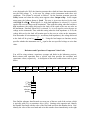
1
Kim A. Winick1
Department of Electrical Engineering and Computer Science
University of Michigan
Ann Arbor, Michigan
Introduction to Signals and Systems
Laboratory Manual
EECS 216
Copyright Kim A. Winick 2007
1
With modifications by Professors Grizzle and Wakefield, Fall 2007.
2
Preface
In the spring of 2006, the EECS faculty decided to revise portions of our curriculum. In
particular starting in the winter of 2007, EECS 206 (“DSP First”) was to be eliminated as
an EE and CE core course requirement and replaced by a required course on continuoustime, linear systems, EECS 216. A junior-level continuous-time, linear systems course,
EECS 306, was already offered as part of our degree program, but it was not a degree
requirement. It was anticipated that the lecture material in the new EECS 216 would be
quite similar to that already covered in the existing EECS 306, i.e., zero-state response,
zero-input response, impulse response, convolution, frequency response, Fourier series,
filtering, Fourier transform and Laplace transform with applications to signal processing,
communications and control. In an effort to enhance the student experience and to make
the connection between the mathematics and applications more transparent, it was
decided that a hardware-based laboratory would be added to the course. Professor
Wayne Stark and myself were the main proponents behind such an approach. Our
Department Chair at the time, Professor David Munson, was also a strong advocate for
improving and increasing our undergraduate laboratory offerings. I took the
responsibility for developing a new set of laboratory projects for EECS 216, and this
effort got underway in the summer of 2006, with continuing efforts in the fall of 2006
and the winter of 2007. Four projects were developed and the labs were offered for the
first time in the winter semester of 2007. Efforts to refine, modify and make additions to
the labs, as well as to improve the student experience, remain an on-going activity.
3
Acknowledgments
The completion of the laboratory projects described in this manual would not have been
possible without the help of others. Professor Wayne Stark assisted with the development
of Lab I during the summer of 2006, and Francine Shammami, an undergraduate student,
helped test portion of this first lab experiment. The electronic design of the pre-built AM
radio front-end used in Lab III was copied from a similar lab experiment offered at the
University of Illinois. Special thanks go to James Shuster, an undergraduate. James,
with the help of Dr. Kurt Metzger, did the PC board layout, assembled the first prototype
of the radio front-end and demonstrated successful operation of the complete AM radio.
He also bread-boarded and tested the PD controller described in Lab IV. A substantial
amount of work is required to bring a new undergraduate laboratory course on-line for
the first time. Lindsay Allen, along with Ben Morris and Xing Zhou, were GSI’s for
EECS 216, in winter semester of 2007, the first time the course was offered. They
accepted and worked through the inevitable frustrations associated with such an effort.
Special thanks are due to Lindsay Allen, who was always enthusiastic about the project
and was committed to its successful outcome. During the summer of 2007, Lindsay
Allen also worked diligently to modify and improve various portions of the laboratory
projects based upon our experience of the previous semester. The EECS lab support
team, consisting of Dr. Alexander Ganago, Rob Giles and Mike Stander provided
outstanding lab support services. Rob Giles assembled multiple copies of the AM radio
front-end, Mike Stander ordered parts when necessary, and all three of them
upgraded/maintained the lab bench equipment and proffered welcome advice and
encouragement. Dr. Kurt Metzger provided valuable technical support in real-time and
upon demand, and he was always more than willing to serve as a listening board. Finally
a special thanks go to our many excellent undergraduate students who make teaching
worthwhile. I hope that they enjoy these lab projects as much as I have enjoyed
developing them.
Kim A. Winick
Ann Arbor, Michigan
August 2007
4
Contents
Preface
Acknowledgments
Introduction
History
References
The Lab Projects
Laboratory Rules
Safety First
The Honor Code
Laboratory Attendance
Laboratory Assignments
Equipment/Component Issues
Equipment and User Manuals
Scope Connect Software
Impedance of Laboratory Equipment and Loading Effects
Resistance and Capacitance Value Codes
Lab I: Introduction to LTI Ssytems
Lab II: Frequency Discriminator and FSK Demodulation
Lab III: AM Radio Receiver
Lab IV: PD Controller
Appendix A – Scope Connect Software
Appendix B – Tutorial on Scope and Function Generator Use
Introduction
5
History
Welcome to EECS 216: Introduction to Signals and Systems! EECS 216 is a basic
course on continuous-time linear systems. This subject material is an electrical and
computer engineering requirement not only here at Michigan, but also at nearly all other
universities worldwide. The theory and techniques you will learn in this course can be
used to analyze and solve a wide range of important problems, related to signal
processing, communications, control, dynamical systems and circuits. Although linear
system theory may appear rather abstract and theoretical at times, the subject developed
out of a need to understand the principles that govern the operation of important real-life
systems. There is hardly any electrical device or algorithm in use today whose operation
does not depend in some way or another on linear system theory. Without linear system
theory, many of the sophisticated electronic products that we take for granted in our
everyday lives, including radios, televisions, cellphones and iPods, would not be in
existence.
There is an old Armenian saying that “He who lacks a sense of the past is condemned
to live in the narrow darkness of his own generation.” Thus we will digress very briefly
to make some comments regarding the history of linear system theory as it relates to the
topics covered in EECS 216 [1]. These topics include, but are not limited to, steady-state
and transient response, frequency response, filtering, impulse response, convolution,
Fourier and Laplace transforms, poles and zeros, linear feedback and stability. As the
famous physicist and chemist, Josiah Millard Gibbs (1839-1903) once said, “One of the
principal objects of theoretical research in any department of knowledge is to find the
point of view from which the subject appears in its greatest simplicity.” This fact has
served to drive the development of linear system theory to its current embodiment, which
is both elegant and powerful. The reader may find it difficult to appreciate the historical
vignette presented below due to a lack of his or her knowledge of linear system theory.
Hopefully the completion of this course will serve as a remedy, and it is suggested that
the brief history presented below might be profitably re-read at the conclusion of the
semester.
The input/output relationship of a single-input/single-output, continuous-time, linear
system can be mathematically modeled by a linear, constant coefficient, differential
equation. Thus in some sense, the study of linear systems is both a qualitative and
quantitative study of these equations and their solutions. The development of differential
equations, of course, had to await the arrival of calculus. Calculus was developed in the
late 17th century by Issac Newton (1642-1727) and Gottfried Wilhelm Leibniz (16461716). After the invention of the calculus, a number of important problems in mechanics
were formulated in terms of differential equations by members of the Bernoulli family.
The general treatment of constant coefficient linear differential equations was developed
by the great Swiss mathematician and physicist Leonhard Euler (1707-1783) in 1739.
In the mid-1800’s George Boole (1815-1864) and Robert Bell Carmichael described
powerful symbolic methods for solving differential equations that are known today as
operational calculus or operator methods. These methods allow one to change a
differential equation into an algebraic one that admits an easy elementary solution. The
6
English mathematician and physicist Oliver Heaviside (1850-1925) further developed the
operational approach in 1893 and was first to apply it to problems involving electricity
and electromagnetism.
It is fair to say that the development of linear systems (as covered in EECS 216) was
driven primarily by the need to understand and design of AC electrical power generation/
transmission equipment and telephone/radio electronics, with these efforts starting in the
late 1800’s and ending in the early 1930’s. In the late 1800’s and early 1900’s AC
motors and power generating equipment were being developed in the United States for
the first time by a number of businesses, including the recently formed General Electric
Company. Carl Steinmetz (1865-1923), an employee of General Electric, developed
mathematical techniques, including the phasor method and complex impedance (topics
taught in EECS 215) for analyzing the steady-state response of AC electrical equipment
subject to a sinusoidal excitation [2]. This work served as a precursor to more general
frequency domain methods, including eigenfunctions and the frequency transfer function
concept. It was well-known to Steinmetz and others at the time that changing conditions,
such as fluctuations of load, would cause power systems to depart from steady state and
exhibit transient behaviors.
In 1909 Steinmetz published a classical mathematical
analysis of these transients based on the theory of linear, constant-coefficient, differential
equations that describe the current and voltages in electric circuits through applications of
Kirchoff’s cicruit laws [3]. His theory for the solution of these differential equations,
however, was rather complicated, and this fact provided the impetus to find more
efficient and transparent methods of attack. Heaviside’s operation calculus was applied
dn
to these problems. In Heaviside’s approach, the differential operator n appearing in
dt
these differential equations was replaced by the variable pn, thus converting the
differential equation into one that is algebraic, i.e., a polynomial in the variable p.
Heaviside then developed a method to convert this algebraic equation back into a timedomain solution of the differential equation [4]. Heaviside’s approach lacked rigor and
was difficult to justify and understand. John Renshaw Carson (1886-1940) advanced the
theory considerably when he expressed the solution of linear, constant coefficient,
differential equations in terms of an integral involving the unit step response of the circuit
[4], [5]. Today this integral operation is known as the convolution, and the derivative of
the step response is called the impulse response. Carson then related the impulse response
to the complex impedance, or equivalently system transfer function, of the circuit through
the Laplace transform. He also demonstrated that Heaviside’s results were a special case
of his theory. Carson’s theory and methods now form the backbone of basic linear
system courses as currently taught. The American academics, Ernst Julius Berg (18711941) and Vannevar Bush (1890-1974) did much to popularize these new methods
through their teaching and writings [6], [7].
By the early 1930’s, the linear systems
tools, such as impulse response, convolution, Laplace transform and frequency response,
had taken on the form they currently have today. Using these tools makes it possible to
analyze both the steady-state behavior and transient behavior of linear, time-invariant
systems with little effort.
Today there are many applications of linear systems that involve feedback, a few of
which will be discussed in EECS 216. The concept of electronic feedback was first
introduced by Edwin Howard Armstrong (1890-1954) in 1912, while he was an
7
undergraduate student at Columbia University. At the time, Armstrong was working on
radio technology using the recently invented vacuum tube triode. Armstrong observed
that by using positive feedback he could build high gain (regenerative) amplifiers and
oscillators that were to become a staple of early radios. Along with radio, telephone
systems were also being developed in the early 1900’s. In the 1920’s, the development
of long-distance telephone transmission systems, however, was being hampered by the
inability to build constant gain amplifying circuits. In 1927 at the American Telephone
and Telegraph Company, Harold Stephen Black (1898-1983) invented the concept of
negative electronic feedback to solve this problem [8], [9]. Using this technique, Black
was able to build amplifiers whose gain was fixed and relatively independent of the openloop amplifier parameters. Black’s seminal work served as the starting point for the
development of modern electronic, linear, control theory. Major contributions to
understanding the stability of these negative feedback systems were made by Harry
Nyquist (1889-1976) [10] and Hendrik Wade Bode (1905-1982) [11] in the 1930’s using
frequency domain concepts.
References
1. S. Puchta, “On the Role of Mathematics and Mathematical Knowledge in the Invention
of Vannevar Bush’s Early Analog Computers,” IEEE Annals of the History of
Computing, vol. 18, no. 4, pp. 49-59 (1996).
2. C. P. Steinmetz, Theory and Calculation of Alternating Current Phenomena, with the
assistance of Ernst J. Berg, McGraw Hill Publishing, New York (1897).
3. C. P. Steinmetz, Theory and Calculation of Transient Electric Phenomena and
Oscillations, McGraw-Hill Publishing Co., New York (1909).
4. J. R. Carson, “Electrical Circuit Theory and the Operational Calculus,” Bell System
Technical J., vol. 4, no. 4, pp. 685-761 (1925); vol. 5, no. 1, pp. 50-95 (1926); vol. 5, no.
2, pp. 336-384 (1926).
5. J. R. Carson, Electric Circuit Theory and the Operational Calculus. New York:
McGraw-Hill Publishing Co. (1926).
6. S. Hensel, “Ernst Julius Berg – Educator and Proselytizer of Heaviside Calculus,”
IEEE Potentials, pp. 57-60 (1994).
7. V. Bush, Operational Circuit Analysis With an Appendix by N. Weiner. New York:
Wiley & Sons (1929).
8. H. S. Black, “Stabilized Feed-back Amplifiers,” Elect. Eng., vol. 53, no. 1, pp. 114120 (1934). Reprinted in Proc. IEEE, vol. 87, pp. 379-385 (1999).
9. H. S. Black, “Inventing the Negative Feedback Amplifier,” IEEE Spectr., pp. 54-60
(1977).
10. H. Nyquist, "Regeneration Theory," Bell System Technical Journal, vol. 11, pp. 126147 (1932).
11. H. W. Bode, “Relations Between Attenuation and Phase in Feedback Amplifier
Design,” Bell Sys. Tech. J., vol. 19, no. 3, pp. 421-446 (1940).
8
The Lab Projects
The laboratory component of EECS 216 consists of the four laboratory projects listed
below.
Lab I: Introduction to lab equipment. Illustration of basic LTI concepts linearity, time-invariance, step response, impulse response, convolution integral,
frequency response.
Lab II: Filtering, envelope detectors, frequency discriminator and frequency shift
keying (FSK) receiver.
Lab III: AM Radio.
Lab IV: PD Controller.
It is a natural tendency of engineering students to categorize courses as being either
“theoretical” (i.e. highly mathematical) or “practical” in nature. Such a characterization,
however, is usually an oversimplification that obfuscates the true nature of the subject.
Both theory and practice go hand-in-hand and are simply different sides of the same coin.
Good theory allows one to solve important, practical problems, and the absence of a good
theoretical understanding makes it difficult or impossible to design and construct
sophisticated systems. On the other hand, the construction of systems and devices
validates the theory upon which they are based, and greatly increases the value of that
theory. As an engineer you will enhance your value by developing expertise in both
theory and practice.
The four laboratory projects in EECS 216 have been carefully chosen to both reinforce
and extend the material covered in the lectures. These projects have also been chosen to
illustrate the close interplay between theory and practice. You will be building real
operational systems, such as FM discriminators, AM radio receivers and controllers.
Laboratory Rules
Safety First
9
The voltages used in this laboratory are in the range of 12 V and the currents are low, and
thus there is little risk of a serious electrical shock. Nonetheless the power supply should
be turned off while assembling or making modifications to your circuits. Also you
should always put safety first and err on the side of caution. The lab equipment itself
runs on 120 V, 60 Hz AC as provided by the wall electrical outlets in the lab room.
These are the same outlets that you will find in your home, dormatory room or apartment.
This voltage can result in electrocution under some conditions and thus due care is
always warranted when working with these voltages. It is important to follow the
instructions below at all times.
• Immediately report any dangerous conditions, such as stripped or frayed 120 VAC
electrical cords, sparks in lab equipment, loose wall sockets, burning odors, etc to your
lab instructor.
• In case of emergency (fire, medical, police, etc.) immediately notify your lab instructor
and/or call 911. There is a phone in the lab near the door. Identify your present location,
the nature of the emergency and your name to the respondent on the phone.
• No student is allowed to work in the lab alone at any time. The student must be
accompanied at all times by either a laboratory partner or a lab instructor.
• Immediately report any equipment failures to the lab instructor.
• Any student who knowingly attempts to apply electrical shocks to either him or herself
or to other students in the lab will immediately be denied access to the laboratory for the
remainder of the semester.
• When in doubt about safety, always ask your lab instructor for help and do not touch
anything.
The Honor Code
The College of Engineering Honor Code applies to all work, including the Pre-Lab and
Post-Lab assignments. Every student is expected to abide by the Honor Code. Please
write, sign and date the following statement on the first page of all your lab assignments:
“I have neither given nor received aid on this assignment, nor have I concealed any
violation of the Honor Code.”
Lab assignments lacking the Honor Code statement and the author’s dated signature will
not be graded.
10
Laboratory Attendance
Attendance in your registered lab section is mandatory. Given the demands on use of the
laboratory room by other students, both those in EECS 216 and those in other EECS
courses, there is little if any time to make up missed labs. If you need to reschedule a lab,
inform your lab instructor (preferably one week) ahead of time.
Laboratory Assignments
Pre-Lab, In-Lab and Post-Lab
The first two and the last laboratory projects will occupy one three-hour lab session each,
while the third lab may require two consecutive weeks. You will be provided with a
detailed set of instructions and problems for each of these four labs. Each lab will
consist of three segments – Pre-Lab, In-Lab and Post-Lab. The Pre-Lab will introduce the
topic to be studied, will state the goals of the project and will provide detailed technical
information related to the subject. This technical information will contain a concise
review, and in some cases an extension, of pertinent theoretical material that has been
covered in lecture. The last section of the Pre-Lab will contain a set of assigned
problems that will help you to draw important conclusions and develop a mastery of the
subject material. You will need to turn in your solutions for the Pre-Lab assignment
when you first come into the lab at the start each new lab project. You should make a
copy of your Pre-lab assignment for yourself and also bring it to the laboratory,
since it will assist you in doing the in-lab work. You may find some of the Pre-Lab
assignments a bit long and a bit difficult, but they are an essential portion of the lab.
Failure to complete these assignments will make it difficult for you to fully understand
and successfully complete the actual lab project. Once in the lab, you will follow the InLab instructions to construct, analyze and measure the performance of your
devices/systems. You will collect and save data (in your personal computer workspace,
or email it to yourself or place it on a USB memory-stick) for later analysis, and in some
cases you will also be asked to demonstrate to your lab GSI, before you leave the lab, that
your device/system operates properly. After you have completed the entire project and
left the laboratory, you will be required to solve a set of assigned problems, i.e., a PostLab, that are related to the data collected in the lab. In many cases, an important part of
this Post-Lab assignment will be comparing your collected data against the predictions of
theory that you computed as part of the Pre-Lab. You will turn in the Post-Lab
assignment the week after you have completed the lab at a place and time to be
announced by your lab GSI or course instructor. In general, both the Pre-Lab and PostLab assignments will require graphing of both experimental data and theoretical results.
These plots will be produced using Matlab. Below you will find some additional
comments on plotting. You will need to use the appropriate Matlab plotting commands.
(1) The points in a theoretical plot should be connected by a line and enough points
should be used so that the line is smooth rather than jagged in appearance.
11
(2) Lines should not be used to connect the points in experimental data, and each data
point should be indicated by a marker, such as an “x”.
(3) If your plot contains more than one curve or set of data, then it should contain a
legend that labels the separate data sets (Matlab legend command).
(4) Each axis in your plot should be labeled and your plot should have a title (Matlab
Title command).
(5) Each plot must have grid (Matlab grid command).
(6) Use the specified Matlab axis command when requested to draw your plot.
The laboratory contains ten student workstations, with two students per workstation.
You will work with a partner of your choosing (it can be a different partner for each lab)
while in the lab to construct the necessary circuits and collect data. Your lab circuits will
be constructed on the protoboards that are located in racks above each lab workbench.
You and your partner will share a single board for each lab project. The lab protoboards
are numbered on their back side. You will leave your protoboard assemble for the entire
two weeks of each of the four lab projects. You will use the lab supplied tape and
markers to label (EECS 216, lab section #, lab project number, and your name) the back
side of your board. You will also use the marker and tape to label the rack slot into
which your board will be stored between labs. At the conclusion of each lab project, you
need to disassemble your board. You will discard all wires and resistors, saving only the
op-amps, diodes and capacitors that your lab GSI will collect.
The Pre-Lab and Post-Lab assignments are to be done individually without any
assistance from other students in the class or from your lab partner. On the outside cover
of each lab assignment PRINT clearly:
• Your Name
• Your e-mail address
• EECS 216 and semester (e.g., Fall 2007)
• The lab project number (1-4)
• Your lab section number
• Your lab instructor’s name
• The signed and dated Honor Code pledge
Your lab assignments should be completed carefully and neatly. Every page should be
numbered, and the pages stapled together in consecutive order. For each of your
solutions indicate the corresponding number of the assigned problem. There is absolutely
no need to type your solutions. You may use either pencil or pen. Your plots must be
done using Matlab.
Equipment/Component Issues
Equipment and User Manuals
12
Each student workstation is equipped with a digital storage oscilloscope (Agilent
DSO3102A, 100 MHz, 1 GSa/s), a function generator (Agilent 3320A, 20 MHz, arbitrary
function), a DC power supply (HP E3631A, 0-6 V 5A/0-+25 V 1 A), volt-ohm
multimeter (HP34401A), and a networked PC. This is the same equipment currently
being used for the EECS 215 lab. Data sheets and user manuals, if needed, can be found
on-line via the web for each of these instruments:
• Scope data sheet: http://cp.literature.agilent.com/litweb/pdf/5989-2235EN.pdf
• Scope user manual anual: http://cp.literature.agilent.com/litweb/pdf/D3000-97012.pdf
•Function generator data sheet: http://cp.literature.agilent.com/litweb/pdf/59888544EN.pdf
•Function generator user manual: http://cp.literature.agilent.com/litweb/pdf/3322090002.pdf
•DC power supply data sheet:
http://www.equipland.com/objects/catalog/product/extras/10386_E363xA.pdf
• DC power supply user manual: http://cp.literature.agilent.com/litweb/pdf/E363190002.pdf
• Multimeter user manual: http://www.mecheng.ohiostate.edu/~kingzett/Manuals/34401MultimeterManual.pdf
Appendix A contains a short tutorial, prepared by Dr. Ganago, on the usage of the
Agilent oscilloscope and function generator.
As opposed to the older analog models, digital oscilloscopes are nice, since they
allow the data to be saved, manipulated and/or processed after collection. Digital
processing, however, can introduce artifacts into the data. For example if the sampling
rate is too low, then aliasing will occur. Also if the analog-to-digital (A/D) converter
does not have sufficient dynamic range, then the data may take on a staircase (as opposed
to smooth) like character due to quantization error. Top-end test and measurement
equipment has sufficiently good specifications to minimize these problems, but the
teaching scopes in EECS 216 lab have more modest capabilities. You will encounter
both quantization errors and sampling problems to some degree in the lab projects, but
they will not be a serious issue.
Scope Connect Software
Your oscilloscope is a digital instrument. It can store data that may be transferred to the
lab PC on your bench for further processing. Scope Connect, software developed by
13
Agilent, is available to perform this data transfer. All of the laboratory projects will
require you to perform such transfers so that you can process and/or plot your measured
data as part of your lab assignments. Appendix B contains a tutorial, prepared by
Lindsay Allen, on the use of the Scope Connect software.
Impedance of Laboratory Equipment and Loading Effects
Scope
The scope input has a finite, rather than infinite, impedance, and thus the scope will draw
some current from the circuit to which it is connected. As a consequence, the scope itself
will affect the circuit voltage that it is being used to measured. Typically the scope input
impedance is sufficiently high (i.e., > 1 MΩ) so that this perturbation is small. There are
situations, however, where the effect will be significant. The input impedance of your
scope can be represented by the following circuit
scope input
1 MΩ
13 pF
Circuit Diagram Representation of Scope Input
If the scope, for example, was being used to measure the voltage across a 10 pF circuit
capacitor, the circuit capacitance would be increased to 23 pF (i.e., 10 pF + 13 pF) due to
the addition of the 13 pF capacitance contributed by the scope itself. When a higher
scope input impedance is desired, a scope probe may be used in place of the standard
BNC connectors. Each lab bench has been provided with a scope probe. When using the
scope probe, the equivalent impedance seen by the circuit
(see http://cp.literature.agilent.com/litweb/pdf/5989-2855EN.pdf) that shown below
5-30 pF
scope probe
14
10 MΩ
scope probe
input
13 pF
1 MΩ
Circuit Diagram Representation of a 10X Scope Input With Circuit Probe
The capacitance of the scope probe can be adjusted, but there will be no need for you to
do so in this lab. If, for simplicity, we ignore the capacitances in the above circuit, we
note that the voltage drop at the scope input (i.e., across the 1 MΩ resistor) will be
approximately 1/11 of that at the probe input. Thus in order for the scope to give a
proper voltage reading it needs to know that a scope probe, as opposed to the standard
BNC cables, is being used. Usually the scope will automatically recognize the presence
of the scope probe. One of the scope menus, however, allows the user to specify that a
10X scope probe is being used.
function generator
The function generator has the following Thevenin equivalent circuit representation,
where Voc is the open-circuit voltage set by the user and 50 Ω is the Thevenin equivalent
impedance set by the instrument.
50 Ω
Voc
VL
ZL
function generator
load
Thevenin Equivalent Circuit Representation of Function Generator Output
The output voltage the user sets on the function generator via the instrument’s front panel
ZL
V , where ZL
is Voc, while the voltage delivered to load, VL, will be given by
50 Ω + Z L oc
is the load impedance. Thus when the load impedance is very high VL ≈ Voc and when
1
the load is 50 Ω, VL is given by VL = Voc . Since loads often have very high impedance
2
15
or are designed to be 50 Ω, the function generator has a built in feature that automatically
sets the load voltage, VL, to the user set voltage on the instrument under these two
conditions. This feature is activated as follows: On the function generator press the
Utility button and when the utility menu appears chose Output setup. In the output
setup menu, the leftmost button is Load. The user is given two choices for the load,
either High Z or 50 Ω. When high Z (i.e., high load impedance) is selected, Voc is set to
equal to the user set voltage on the instrument. Thus with this setting when the load has a
high impedance, the voltage delivered to the load will be equal to the user set value on
the instrument. Similarly when 50 Ω is selected, Voc is set to equal to twice the user set
voltage on the instrument. Thus with this setting when the load impedance is 50 Ω, the
voltage delivered to the load will remain equal to the user set value on the instrument.
Note that under all circumstances (i.e., an arbitary load impedance), the voltage delivered
ZL
V . Using the load output set function, merely
to the load will be given by
50 Ω + Z L oc
specifies whether the instrument sets Voc equal to the user specified voltage or twice that
value.
Resistance and Capacitance Component Value Codes
You will be using resistors, capacitors, op-amps and diode in the laboratory projects.
Both resistors and capacitors have a special code that specifies the resistance and
capacitance values, respectively. A description of the color-coded resistor code is given
below:
Black
0
Brown Red
1
2
Orange Yellow
3
4
Green Blue
5
6
Violet
7
Gray
8
White
9
1st digit
2nd digit
multiplier
tolerance
quality
First find the tolerance band located at or near one of the two ends of the resistor, which
is typically gold (5%) or sometimes silver (10%). Starting at the opposite end, identify
the number associated with the color of the first band and write this number down. Now
identify the color of the next band and write this number down immediately to the right
16
first number. Next identify the number associated with the color of the next (multiplier)
band. Write this number of zeros immediately to the right of the preceding two numbers.
This final value equals the resistance in ohms. If the multiplier band is gold, then move
the decimal point one to the left, and if it is silver move it two places to the left. If there
is one more band past the tolerance band (which is not always the case), then this last
(quality) band indicates the percent of these components that will fail per 1000 hours of
operation when dissipating the maximum assumed wattage. For example a resistor with
the following four bands red, yellow, green, silver will have a nominal resitance of 2.4
MΩ with an uncertainty of + 10%.
The code for capacitance values is as follows:
Large capacitor have the value and units printed plainly on them, such as 10.uF (ten
micro Farads). Smaller disk types along with plastic film types, however, often have just
2 or more commonly three numbers printed on them. The units are in pico-Farads. As an
example: 93 printed on a small disk can be assumed to be 93 pico-Farads. When three
numbers are present, the first two are the first two significant digits, while the last
number is the multiplier, i.e., the number of zeros that needs to be appended to the right
of the first two significant digits. So for example 461 would denote a capacitance of 460
pF.