1
USER GUIDE
Cross Platform Control
TM
This Guide covers the operation
of the M1Gold and M1EZ8 Controller models
L519 Rev. F 05/09
M1 Cross Platform Controllers - User Guide
This system consists of a main control unit, one or more keypads, and various contact
sensors and detectors. The control unit is generally placed in an out of sight location
such as a closet, utility room, etc. It houses the main electronics and a backup battery
for standby power. Ordinarily, there is no reason for anyone except the installer or
service personnel to have access to the control unit.
Keypads are the primary user interface, and they display the current system status
using their LCD screen and LED lights. Keypads also produce audible feedback at
appropriate times. Generally speaking, a keypad is installed adjacent to any primary
entry/exit door(s).
THIS MANUAL IS PROVIDED TO ACQUAINT YOU WITH THE OPERATION OF THE
SYSTEM AND HELP YOU BECOME PROFICIENT WITH IT’S OPERATION. ALL
USERS SHOULD READ AND FOLLOW THE INSTRUCTIONS AND CAUTIONS IN
THIS MANUAL. FAILURE TO DO SO COULD RESULT IN THE SYSTEM NOT
WORKING PROPERLY. KEEP THIS MANUAL IN AN EASY TO ACCESS LOCATION.
READ AND FOLLOW THESE INSTRUCTIONS CAREFULLY. IF YOU DO NOT
UNDERSTAND ANY PORTION OF THIS MANUAL OR IF YOU HAVE ANY
QUESTIONS ABOUT YOUR SYSTEM, CONTACT THE INSTALLING COMPANY FOR
ASSISTANCE.
PLEASE BE AWARE OF THE FOLLOWING:
The level of security obtained is directly related to two major factors.
1. The quantity, quality, and placement of sensors attached to this system.
2. The knowledge and operating skills that you have of the system, including but not
limited to the weekly testing of the complete system.
3. If you are not happy with the level of protection provided by the location of your
sensors then discuss this with your installation company immediatly.
Important notes when preparing a security/safety plan for your home or business:
1. This system is an electronic device and is subject to failure or malfunction. You
should not rely on it as your single source of security.
2. This system will not work without power.
3. Reporting of Alarms to an offsite 24 hour monitoring company will not work if your
phone line is cut or not available without the inclusion of back up alternative
system.
4. This system should be tested weekly.
5. Audible warning devices will need to be loud enough, wired correctly, and
properly placed to provide adequate notification of an alarm event.
6. Smoke and heat detectors may not detect smoke and heat in all situations.
7. Only qualified security professionals should install and maintain this system.
8. It may be possible to arm this system WITHOUT the backup battery connected or
with less than an adequate charge. Weekly testing of the system with AC Power
removed should be performed to verify that the battery is connected and
adequately charged.
9. Care should be taken after testing to make certain that AC Power is restored.
Page 2
M1 Cross Platform Controllers - User Guide
TABLE OF CONTENTS
Understanding The Keypad ........................................................................... 4
System Notes ................................................................................................. 6
Operating The System ................................................................................... 7
User Codes .............................................................................................................. 7
Checking the Ready Status ................................................................................... 7
Arming in the “Away” Mode .................................................................................. 8
Arming in the “Vacation” Mode ............................................................................ 8
Arming in the “Stay” Mode .................................................................................... 8
Auto Stay Arming .................................................................................................... 9
Using the Quick Arm .............................................................................................. 9
Changing Stay Modes While Armed ..................................................................... 9
Bypassing Zones .................................................................................................. 10
Quick Bypassing of Violated Zones ................................................................... 10
Disarming and Resetting the System ................................................................ 11
Alarm Acknowledgments ..................................................................................... 12
Troubles ................................................................................................................. 12
Chime Mode, Turning On and Off ....................................................................... 13
Keypad Menus .............................................................................................. 14
Menu 1-View/Control Automation Functions .................................................... 14
Menu 2-Reset Smoke Detectors ......................................................................... 16
Menu 3-Walk Test Area (zones) ........................................................................... 17
Menu 4-View History Log .................................................................................... 17
Menu 5-View (Zone) Status ................................................................................. 18
Menu 6-Change User Codes ............................................................................... 18
Menu 7-Automation Custom Settings ................................................................ 19
Menu 8-System Settings ...................................................................................... 19
Operation Via Telephone ............................................................................. 21
Fire Safety & Maintenance .......................................................................... 23
Silencing a Fire Alarm .......................................................................................... 23
Resetting Smoke Detectors ................................................................................ 23
Acknowledge/Reset an Alarm ............................................................................. 23
Household Fire Safety Audit ............................................................................... 23
Emergency Evacuation Plans ..................................................................... 24
System Testing ............................................................................................. 25
FCC Statements (Part 15 & 68) ................................................................... 26
Glossary ........................................................................................................ 27
Page 3
M1 Cross Platform Controllers - User Guide
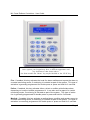
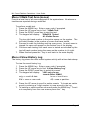
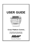
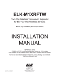
Understanding The Keypad
Ready Light - This light will be ON when all burglar zones are secure and the system
is OK for arming. If this light is OFF, one or more zones are violated (not secure).
For maximum security, all zones should be secured before the system is armed. If
this light is FLASHING, it indicates that the system may be Force armed. Refer to the
last paragraph under “Checking the Ready Status on page 7 for more information.
Armed Light- This light will be ON when the system is armed. The mode of arm will
be indicated by the LCD display and the Exit or Stay lighted pushbuttons. This light
will be OFF when the system is disarmed.
Exit Key - This is a lighted key. When the Armed light is ON and this Exit light is ON,
the system is armed in Away (not occupied) mode. All perimeter sensors and interior
motions will be active.
Stay Key - This is a lighted key. When the Armed Light is ON and this Stay light is
ON, the system is armed in Stay (occupied) mode. Only perimeter doors and
windows will be active. Interior motions will not be active.
Chime Key - This is a lighted key. When the Chime Light is ON, a tone or announcement will be heard when certain zone(s) are opened. If OFF the chime mode is off.
Bypass Key - When the Bypass Light is ON, one or more zones have been excluded
or bypassed. If OFF”, no zones are bypassed.
*
Key - This key serves as a clear or reset key. If an error is made while entering
digits, pressing this key clears the error. Three presses is a master clear.
# Key - This key is currently a duplicate of the Bypass key.
MENU Key - This key is used to access the extended user menus.
Function Keys F1 thru F6 - Each key is independently programmable and lighted.
The activation as well as the lighting is programmed by the installer for special events
or conditions such as Fire, Police, or Medical emergency activation. However, these
keys may also be used for non-alarm type applications such as: gate or door openers,
lights, irrigation controls, etc. Activation may be programmed for single or double
press, which helps prevent accidental activation. If double press is programmed, it will
also be possible to activate the key by pressing and holding it for at least 2 seconds.
(Some model keypad may only have F1-F4 Function Keys)
See explanation of Emergency Activation Keys on opposite page.
Page 4
M1 Cross Platform Controllers - User Guide
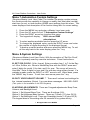
NOTE: Due to the numerous models of keypads available on this
series system your keypad may have a different appearance and
key locations to that shown above.
On Some models the “Menu” key maybe labelled as the “ELK” key
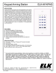
Fire - If enabled, this key activates the local fire alarm audibles and reports the alarm to
a central monitoring center, if monitoring is included as part of the system. This type of
activation is generally programmed for double press or press and hold for 2 seconds.
Police - If enabled, this key activates either a silent or audible police/holdup alarm,
depending on how the installer programmed it. It can also send a report to a central
monitoring center, if monitoring is included as part of the system. This type of activation is generally programmed for double press or press and hold for 2 seconds.
Medical - If enabled, this key activates a medical alarm condition and sends a report to
a central monitoring center, if monitoring is included as part of the system. This type of
activation is commonly programmed for double press or press and hold for 2 seconds.
Page 5
M1 Cross Platform Controllers - User Guide
System Notes
Central Monitoring Station: _______________________________ Acct. # ______
Installation Company: _______________________________________________
Exit Delay 1 Timer in seconds: _______ Exit Delay 2 Timer: _______
Entry Delay 1 Timer in seconds: _______
Entry Delay 2 Timer: _______
Burglary Alarm (Audible) Cutoff Timer in minutes: _______
Fire Alarm (Audible) Cutoff Timer in minutes: _______
User Code Digits
4 digits ____
or
6 digits ____
F1 Key Function: _______________________ Single Press? Y or N
Silent? Y or N
F2 Key Function: _______________________ Single Press? Y or N
Silent? Y or N
F3 Key Function: _______________________ Single Press? Y or N
Silent? Y or N
F4 Key Function: _______________________ Single Press? Y or N
Silent? Y or N
F5 Key Function: _______________________ SinglePress? Y or N
Silent? Y or N
F6 Key Function: _______________________ SinglePress? Y or N
Silent? Y or N
CAUTION
We strongly suggest not to record your user codes in this
manual.
Page 6
M1 Cross Platform Controllers - User Guide
Operating The System
Read this entire section before attempting to operate the system.
User Codes
<>
User Codes are required for arming, disarming, and to authorize certain features
of your system. User codes can be either 4 or 6 digits (refer to System Notes).
<>
If a mistake is made while entering a user code, press the asterisk (*) key and
enter the code again.
<>
To prevent someone from hunting for a code the system can be set to temporarily
lockout the keypad after repeated incorrect codes. Consult your installer or
installation record sheet for the number of incorrect attempts allowed.
Checking the Ready Status
<>
When the Ready light is off, one or more zones are violated. The display will show
“Not Ready x Zn” where the x represents the number of violated zones. The system
cannot be armed until you secure or bypass the violated zone(s).
<>
To identify violated zones, press the UP arrow key repeatedly to view each zone by
name and number. If a zone is programmed as bypassable, you may bypass it
(permanently exclude it) for the immediate arming cycle by pressing the Bypass
key + zone number + the Bypass key again. The display will show “Ready w/
Bypass” once the system is ready to be armed. The Bypass key may require the
entering of a user code with an appropriate authority. NOTE: Zones not programmed
as bypassable must be secured before the system can be armed.
<>
When the Ready light is on steady the alarm system is ready to be armed. The
display will show “Ready to Arm”.
<>
If the Ready light is flashing, it indicates the system can be armed even though
one or zones are violated. This only occurs if the violated zones are programmed
as force-armable. Arming will temporarily exclude these violated zones from the
system. If a force armed zone becomes secure while the system is armed, it will
automatically become live, meaning that it can activate an alarm if violated. This
feature is handy for a garage door. The system can be armed while the door is up.
After backing out of the garage and closing the door, the garage door will become
normal and it will be re-included into service.
Page 7
M1 Cross Platform Controllers - User Guide
Arming in the “Away” Mode
Away mode arming is the highest arm level, intended for use when the
premises is unoccupied. Both perimeter and interior zones will be armed.
The Ready light must be on or flashing for the alarm system to be armed.
Secure all protected doors and windows.
1. Enter a User code.
2. The Armed and Exit lights will illuminate and the exit tone will start.
4. Leave the premises during the exit delay.
5. At the end of the exit delay the alarm system will be armed Away.
During the last 10 seconds of the exit delay time the exit tone will beat faster
to warn you that the time is about to expire. If you feel that you will be unable
to get out and close the exit door in time we recommend that you return to the
keypad, disarm, and rearm.
Arming in the “Vacation” Mode
Vacation mode is a second level of Away mode. It can be used to activate
energy saving automation features when the building will not be occupied for
an extended period of time. After arming, pressing the Exit button at any time
during the exit delay time to change the armed mode to vacation.
Arming in the “Stay” Mode
Stay mode arming is intended for use when the premises is occupied. All
perimeter doors and windows are armed, and all interior zones are excluded.
Secure all protected doors and windows.
1. Enter a User code.
2. The Armed and Exit lights will illuminate and the exit tone will start.
3. Press the Stay key. The key will light up. All interior zones will be
excluded and the exit tone will be silenced. Delayed entry/exit zones
will still be delayed.
4. (Option, may not be enabled) Additional presses of the Stay key
may allow scrolling to different modes of Stay arming if enabled by
your installer. Additional modes are Stay Instant, Stay Night, and
Stay Night Instant.
Page 8
M1 Cross Platform Controllers - User Guide
Auto Stay Arming
(Optional) If this feature was enabled by your installer, it will automatically
change the arm mode from Away to Stay if you none of the perimeter delayed
doors are opened during the exit delay countdown time.
Secure all protected doors and windows.
1. Enter a User code.
2. The Exit key will light and the exit tone will start.
3. As long as you don’t open or exit through any delayed doors, the
Stay light will come on and the Exit light will go off at the end of the
exit delay time. The system is now armed in the Stay mode.
Using the Quick Arm
(Optional) If this feature was enabled by your installer, it will allow arming in
either the Away or Stay modes without having to enter your user code. For
security reasons however, a user code is always required to disarm.
Secure all protected doors and windows.
1. Press the Exit or Stay key.
2. The Armed and mode light (Exit or Stay) will illuminate just as if you
had entered your user code.
Changing Stay Modes While Armed
(Optional) If this feature was enabled by your installer, it permits various
levels of Stay mode arming to be enabled (scrolled) without having to first
disarm the system. The additional Stay mode arming levels may include:
Instant, Stay Night, and Stay Night Instant.
1. Press the Exit or Stay key.
2. The Armed and mode light (Exit or Stay) will illuminate just as if you
had entered your user code.
Page 9
M1 Cross Platform Controllers - User Guide
Bypassing Zones
(Optional) Manual bypassing of a zone will exclude it from the system for the
immediate arming period. * [see notes below] Once the system is armed,
zone(s) that are bypassed will not be able to activate an alarm. The bypass
will remain in effect until: a) the zone bypass is canceled, or b) the system is
disarmed. The Bypass key will be lighted whenever a zone is bypassed.
To
1.
2.
3.
4.
bypass a zone:
Press the Bypass key.
Enter the number of the zone you wish to bypass.
Press the Bypass key again.
The Bypass light will light up if the bypass is accepted. However, if
the zone is non-bypassable an error tone will be heard.
Quick Bypassing of Violated Zones
(Optional) The Quick Bypass feature allows you to bypass all violated zones
with a minimum number of keystrokes. * [see notes below]
To
1.
2.
3.
4.
quick bypass any violated zones:
Press the Bypass key.
Enter 999
Press the Bypass key again.
If the quick bypass is accepted the Bypass light will be illuminated.
However, if any of the zones were non-bypassable an error tone will
be heard.
* Only zones that have been programmed as bypassable can be bypassed.
* Bypassing may additionally require a user code that has been enabled with
the user bypass option.
Page 10
M1 Cross Platform Controllers - User Guide
Disarming and Resetting the System
After entering the premises through one of the assigned Entry delayed zones,
the keypad will sound a continuous entry delay tone. The keypad will display
a count-up of the programmed entry delay time. Refer to the System Notes
for the amount of entry time available.
Disarming
1. Proceed directly to the keypad.
2. Enter a valid user code.
3. The entry delay tone should stop.
4. When the Armed light turns off the alarm system is disarmed.
If a valid user code is not entered before the entry delay time expires, an
alarm will occur. If this should occur proceed as follows:
Disarming and Silencing After an Alarm
1. Proceed directly to the keypad.
2. The display will show the alarm type and first zone that tripped.
3. Enter your user code.
4. The entry delay tone should stop.
5. When the Armed light turns off the alarm system is disarmed.
After an alarm has been silenced by a valid user code, the display
will continue to show the alarm type and zone until a valid user code
is entered a second time. This “Acknowledgment” is designed so
that the user sees what caused the alarm after things are quieted.
Disarming and Silencing During an Alarm
1. Proceed directly to the keypad.
2. The keypad display will show the type of alarm.
3. Enter a user code.
4. The keypad entry tone and the alarm siren/bell will stop.
5. When the Armed light turns off the alarm system is disarmed.
6. If you are certain the alarm was accidental, contact the Central
Monitoring Center to avoid a false dispatch of the authorities.
Page 11
M1 Cross Platform Controllers - User Guide
Alarm Acknowledgments
After an alarm has been silenced by a valid user code, the display will
continue to show the alarm type and zone until a valid user code is entered
a second time. This “Acknowledgment” is designed so that the user sees
what caused the alarm after things are quieted. To reset (clear) the display
the alarm must be acknowledged using the following procedure:
To acknowledge the alarm and reset the system:
1. Enter a user code.
2. The alarm/condition will clear from the keypad display.
Troubles
There are many different types of trouble conditions that can be annunciated
by the system including the following:
Trouble Conditions
AC Power Failure
Low Backup Battery
Telephone Line Fault
Fire Alarm Trouble
Missing Keypad, Expander (Zone or Output)
Communications Fail
Troubles are annunciated by an intermittent beeping from the keypad and a
display of the Trouble condition(s). The beeping may be silenced by pressing
the asterisk * key but the trouble must be acknowledged before any other
keypad operation may continue.
Acknowledging a Trouble condition:
1. Enter a user code.
2. Until the trouble condition is resolved, the keypad will momentarily
flash the condition along with the normal keypad information. If a
new Trouble should occur, the keypad beeping will resume.
Page 12
M1 Cross Platform Controllers - User Guide
Chime Mode, Turning On and Off
Chime is a function which can provide an audible alert whenever certain
doors, windows, or other selected zones are violated. The ideal application is
for annunciating whenever someone enters or leaves the premises through a
normal doorway. However, it can also be used to annunciate abnormal
access to and restricted areas.
NOTE: The M1 Gold control has four selections for Chime: Tone, Voice, Tone/
Voice, and Off. The M1EZ8 control has only two selections for Chime: Tone
or off.
When the Chime mode is On, the Chime key will be lighted.
To turn the Chime mode Off:
1. Press the Chime key one time.
If the Chime mode is off, the Chime key will be dark (not-lighted).
To turn the Chime mode On:
1. Press the Chime key one time to select the Chime Tone mode.
2. Pressing the Chime key a second time within ~30 seconds of the
last press will select the Chime Voice mode.
3. Pressing the Chime key a third time within ~30 seconds of the last
press will select the Chime Tone/Voice mode.
4. Pressing the Chime key a fourth time within ~30 seconds of the last
press will once again turn the Chime mode Off.
Only your installer has be ability to program which doors, windows,
etc. (zones) will be included in the Chime mode.
Page 13
M1 Cross Platform Controllers - User Guide
Keypad Menus
This section explains the use of the most commonly used keypad menus.
For additional instruction, consult the installation company. To reach the
keypad menus press the center navigation key labeled “MENU”. A user code
may be required depending on how the control is programmed. The four
arrow keys around the MENU key are used to scroll, backup, etc. For
example, press the UP arrow key will step to menu 2. Entering a number
from 1 to 9 will jump directly to that menu. Press the RIGHT arrow key to
select a menu.
Menu 1-View/Control Automation Functions
Allows operation of many powerful automation capabilities such as: activation
of individual or group lights, irrigation sprinklers, pumps, gates, etc. There are
6 sub menus: Tasks, Lighting, Outputs, Temperature Sensor, Keypad Temperature, and Thermostat Temperature.
1. Press the MENU key and enter a user code if required.
2. Press the RIGHT arrow key to select menu 1.
3. The first of 6 sub menus; “1-TASKS” will be displayed. Each press
of the UP arrow key will scroll through the other sub menus.
4. When the desired menu displays, press the RIGHT arrow to select.
1-TASKS Can simplify or automate one or more events or actions associated with an otherwise manual task. Example: “Water the Lawn” could turn on
sprinklers for a time period. The state of each task can be viewed and turned
On or Off. “Welcome Home” could turn on one or more lights to a level of
On, Off, Dim, etc. so that a room will look warm and inviting.
To view the state of a TASK, or to control it:
1. Starting from the “View/Control Automation Functions” menu, locate
the Tasks screen and press the RIGHT arrow key to select.
2. Use the UP or DOWN keys to scroll through the list of available
tasks, viewing the state of each one as it displays. To jump directly
to a specific task, enter it’s 2 digit number. (see note on next page)
3. Press the # key to toggle the state of a displayed task. E.G.: If the
state is On, pressing # will turn it Off.
4. To backup or select another sub menu press the MENU key. To exit
out completely from the user menus press the * key.
Page 14
M1 Cross Platform Controllers - User Guide
2-LIGHTING Provides the ability to view and control lights or appliance type
devices. Each lighting device must be programmed and installed before it
can actually do anything. An example of a lighting device is: “Porch Light”,
which could be a powerline carrier lamp module or switch controlled independently from this lighting menu, or from the inclusion in a programmed task.
To view the state of a LIGHTING device, or to control it:
1. Starting from the “View/Control Automation Functions” menu, locate
the Lighting screen and press the RIGHT arrow key to select.
2. Use the UP or DOWN keys to scroll through the available lighting
devices and view their current state. To jump directly to a specific
lighting device, enter it’s 3 digit number. (see note on next page)
3. Press the # key to toggle the state of a displayed lighting device.
E.G.: If the state is On, pressing # will turn it Off.
4. To backup or select another sub menu press the MENU key. To exit
out completely from the user menus press the * key.
3-OUTPUTS Provides the ability to view and control individual outputs. An
output may be a relay used to signal or switch a device On or Off. Outputs
are not necessarily a physical form. Outputs must first be assigned and
programmed by the installer before you can utilize them in this menu. A relay
might be used to control a Pool pump motor. When this output is On the
pump would be running. When the output is Off the pump would be off.
To view the state of an OUTPUT, or to control it:
1. Starting from the “View/Control Automation Functions” menu, locate
the Outputs screen and press the RIGHT arrow key to select.
2. Use the UP or DOWN arrow keys to scroll through the list of available
outputs and view their current state. To jump directly to a specific
output, enter it’s 3 digit number. (see note below)
3. Press the # key to toggle the state of a displayed output. E.G.: If the
state is On, pressing # will turn it Off.
4. Press MENU to backup or select another sub menu. Press * to exit.
4-TEMPERATURE SENSORS Provide the ability to read remote temperature
sensors, if installed. Press the RIGHT arrow key to select this menu, then
press the UP or DOWN arrow keys to scroll through the list of available
sensors. To jump directly to a particular sensor enter it’s two digit number.
The current temperature will be displayed. Press the * key to exit.
Page 15
M1 Cross Platform Controllers - User Guide
5-KEYPAD TEMPERATURE SENSORS Provides the ability to read the inside
temperature sensors in any M1KP keypad. Press the RIGHT arrow key to
select this menu, then press the UP or DOWN arrow keys to scroll through
the list of available keypads. To jump directly to a particular keypad enter it’s
two digit number. The current temperature at the keypad will display. Press
the * key to exit.
6-THERMOSTATS If HVAC thermostats are connected their current temperature may be read from this menu. Press the RIGHT arrow key to select this
menu, then press the UP or DOWN arrow keys to scroll through the list of
available thermostats. To jump directly to a particular thermostat enter it’s two
digit number. The current temperature is displayed. Press the * key to exit.
NOTE: To reduce scroll time, the keypad only displays the entities:
Tasks, Lights, Outputs, Temperature Sensors, Keypads, and Thermostats which are installed, programmed, and selected to “show” on the
keypad. This is done by the installer and can be changed as new
equipment is added. It is also possible to enter a 2 or 3 digit number
and jump to ANY entity, even those NOT selected to “show”.
Menu 2-Reset Smoke Detectors
This is used to reset latched smoke detectors following a Fire alarm trip.
When a Smoke Detector causes an alarm it’s output circuitry will latch ON to
provide a visual identification. IMPORTANT: It will be necessary to reset the
smoke detector circuitry following an alarm in order for any subsequent Fire
alarms to be detected.
1.
2.
3.
4.
5.
Page 16
Press the MENU key. Enter a user code if prompted.
Use the UP or DOWN arrow keys to find “2-Reset Smoke Detectors”.
Press the RIGHT arrow key to select this menu.
The keypad will display “5 Seconds Smoke Output Reset”.
Two beeps from the keypad indicates that the reset is complete.
The keypad will automatically return to the main display.
M1 Cross Platform Controllers - User Guide
Menu 3-Walk Test Area (zones)
Permits a local test of all zones assigned to the system/area. No alarms or
troubles are reported during a walk test.
To
1.
2.
3.
4.
perform a walk test:
Press the MENU key. Enter a user code if prompted.
Press the UP arrow key to find: “3-Walk Test.”
Press the RIGHT arrow key to start the test.
The keypad will display: 000of016 Tested
A1-Violate Zones
The top right hand number is the active zones on the system. The
left hand number is the number of zones that have tested.
5. Proceed to walk the building and trip every zone. As each zone is
tripped it’s name will appear on the bottom line of the display.
6. Continue walk testing until each zone is tested as indicated by the
top left hand number being the same as the number to it’s right.
7. When finished press the * key to exit back to the main display.
Menu 4-View History Log
The history log stores the most recent system activity with a time date stamp.
To
1.
2.
3.
4.
view the event history log:
Press the MENU key. Enter a user code if prompted.
Press the UP arrow key to find: “4-View History Log.”
Press the RIGHT arrow key to select this menu.
The keypad will display: L001:xx/yy hr:mn
<event desc> 00#A$
xx/yy = month & date
hr:mn = hour & min.
00# = zone or user code
A$ = area or partition.
6. Press the UP arrow to scroll to earlier events. To locate an earlier
event try entering a 3 digit number to jump around in the log.
7. To backup or select another sub menu press the MENU key. To exit
out completely from the user menus press the * key.
Page 17
M1 Cross Platform Controllers - User Guide
Menu 5-View (Zone) Status
This allows a comprehensive viewing of the status for all area zones
1.
2.
3.
4.
Press the MENU key. Enter a user code if prompted.
Use the UP or DOWN arrow keys to find “Menu 5-View Status”.
Press the RIGHT arrow key to select this menu.
The first zone is displayed with it’s current status and name. Press
the UP arrow key for the next zone or press the DOWN arrow key for
the previous zone. To jump directly to a particular zone enter it’s
three digit number.. I.E.: To jump to zone 16 enter “016”.
5. When done, press the * key to exit back to the menu selections.
Menu 6-Change User Codes
A Master Level User Code is required to change User Codes.
1. Press the MENU key. You must enter a Master Level User Code.
2. Press the UP arrow key to find: Menu 6-Change User Codes.
3. Press the RIGHT arrow key to select this menu and use the UP
arrow to locate a user OR enter 3 digits to jump to a specific user.
5. The keypad will display: 001:Sel Chg
{name of User}
6. To change the code press the RIGHT arrow and enter the new code
digits. Codes are either 4 or 6 digits in length, depending on how
the installer set up the programming. Refer to the System Notes.
7. If the code is accepted the keypad beeps 3 times. If a long error
tone is heard the keypad will display: “Code Not Authorized”. Press
the RIGHT arrow to “Redo” and repeat step 6 using different digits.
8. To change or edit a name press the RIGHT arrow key followed by
the DOWN arrow key. The cursor starts in the lower left corner.
Select each letter using number keys 1 thru 9. E.G.: Each press of
the 5 key will produce: J, then K, then L, and then 5. To move to the
next letter press the RIGHT arrow. For a space press the Chime
key. To delete a character press the Bypass key. For upper case
press the UP arrow then select a letter. For lower case press the
DOWN arrow. When finished, press MENU key to save the name.
9. To back up to another user or to select another menu press the
MENU key until the correct display is shown.
10. To exit all the way back to the main display press the * key.
Page 18
M1 Cross Platform Controllers - User Guide
Menu 7-Automation Custom Settings
(Requires Master Level User Code) The installer can assign certain automation functions with the capability to change or modify their start date (mm/dd),
start time (hr:mn), or time duration (00000 secs) settings from this menu. This
menu displays a text description of the function along with it’s current setting.
1.
2.
3.
4.
Press the MENU key and enter a Master Level user code.
Press the UP arrow to find: “7-Automation Custom Settings”
Press the RIGHT arrow key to select this menu.
The keypad will display: US01:=hr:mnTIME
<description>
5. To select another available function press the UP arrow.
6. To change the displayed value, press the RIGHT arrow and enter
the number of digits according to the displayed format.
7. To backup or select another sub menu press the MENU key. To exit
all the way back to the main display press the * key.
Menu 8-System Settings
(Requires a Master Level User Code) With the exception of “Set Sys Clock”,
this menu is primarily used by a service technician. It has 8 sub-menus.
81-SET SYS CLOCK (24 hr. format) Enter a number from 1 to 7 for the Day.
ie:1=Sun, 2=Mon, etc. Move to Month/Day/Year with the RIGHT arrow and
enter 2 digits for month, 2 for date, and 2 for year. The cursor will move to
Hour/Min. Enter 2 digits for hour and 2 for minutes using military format. If a
mistake is made, press the RIGHT or LEFT arrow to edit. When done, press
the “MENU” key to save. To exit from user menus press the * key.
82-OUT1 VOICE ADJUST VOLUME ** There are 8 volume level settings for
the internal speakers (Output 1) on non-alarm messages. MAY BE LOUD!!
(This option is not available on M1 EZ8 Ssytems)
83-KEYPAD ADJUSTMENTS There are 3 keypad adjustments: Beep Tone,
Volume, and Backlight Level.
Option 1: Set Keypad Beep Tone There are 9 settings (0-8).
Option 2: Set Keypress Beep Volume There are 7 levels (1-7) plus Off (0).
Option 3: Set Backlight Level There are 9 backlight levels (1-9) plus Off (0).
The keypad dims to this setting after 30 seconds of key press activity.
** Not applicable to the M1EZ8
Page 19
M1 Cross Platform Controllers - User Guide
84-SYSTEM TESTS Allows Battery Test, LCD Test, & Communicator Test.
Option 1: Battery Test Places the battery under load for 30 seconds. Battery
voltage and system current will be displayed. If the voltage falls below 12.2V,
a Low Battery trouble will occur. Replace the battery and repeat test to clear..
Option 2: LCD Test Briefly turns on all the keypad’s display pixels.
Option 3: Communicator Test There are 3 sub-options:
- Silent Test: Sends a communicator test using the first phone number that is
programmed with a test code. The test aborts if no telephone numbers are
programmed with a test code. No noise or tones will be heard.
- Audible Test: ** Same as Silent Test except the dialing and communicator
tones will be heard over the internal speaker(s) for the Installer’s benefit.
- Monitor (Buttset) mode: ** This causes the internal speakers to activate
during any subsequent communicator activity. It cancels itself at midnight
or can be manually canceled by pressing the * key three times in a row.
IMPORTANT: NEVER TEST THE COMMUNICATOR WITHOUT FIRST
NOTIFYING THE MONITORING STATION!
85-CONNECT RP REMOTE PROGRAM Do Not Use except under guidance
of the installation company. There are two options:
Option 1: Pickup on Existing Call The system picks up the phone line and
take over an established voice connection for a quick programming change.
Option 2: Dial out to Remote Computer The system picks up the phone line
and dials the remote computer. It must be set to expect the call.
86-SYSTEM DIAGNOSTICS This is expressly for use by a service technician. There are four options:
Option 1: Data Bus Errors Display the device type and any error retries
accumulated since the last power-up.
Option 2: System Voltage/Current Displays the system’s voltage. Displays
approx. current draw from the power supply. **
Option 3: Zone Voltage Displays the voltage and digital level of a zone,
including the low and high thresholds.
Option 4:Last On Hook Telephone Displays the telephone line voltage during
the last on-hook state.
87-CUSTOM MESSAGE RECORD ** The installer can assign up to 10
custom recordable messages to be used with the telephone voice remote
and/or dialer. Detailed instructions are contained in the installation manual.
Consult your installer for specific instructions on what messages (if any) may
be recorded and for the step by step instructions to record them.
** Not applicable to the M1EZ8
Page 20
M1 Cross Platform Controllers - User Guide
Operation Via Telephone
NOTE: This feature not avaliable with the M1EZ8
The system may be optionally controlled from a Telephone using push-button
“tone” commands. Consult the installer to determine if this option is available.
If available, the control may be operated from an inside telephone, an outside
telephone, or both. Both methods will be discussed in detail below.
Operation from an Inside Telephone:
1. Lift the telephone and listen for dial tone.
2. Press * * * to alert the control. The control will pick, disconnect the
phone line and dial tone, and announce: “Please enter security code”.
3. Enter a valid user code. If code is correct the control should
announce: “Access Authorized”.
4. Enter a menu selection OR press 0 to hear the entire menu.
Operating from an Outside Telephone:
1. Dial-in to the phone number attached to the control. After a
programmed number of rings the control should answer with four
short beeps. If an answering machine picks up, wait for the message
to quit and proceed as follows:
2. Press * * * to alert the control. The control will announce: “Please
enter security code”.
3. Enter a valid user code. If code is correct the control should pickup
announce: “Access Authorized”.
4. Enter a menu selection OR press 0 to hear the entire menu.
Menu Selections: Main menu options are underlined.
For Help press 0. A voice message explains the function of each key.
For Arm Status press 1. Allows the system to be armed or disarmed.
Voice messages will prompt you through the entire process.
For Automation press 2. Certain features of the system or premises may
be controlled from this menu such as: Turning on a light, a pump, a sprinkler
system, etc. Consult your installer. Follow the detailed prompts.
For Trouble Status press 3. If there are any system troubles such as low
battery, AC power loss, etc., they will be announced. Follow the prompts.
Page 21
M1 Cross Platform Controllers - User Guide
For Zone Status press 4. If the system is not ready this menu can be used
to hear the status of any violated zones. Follow the prompts.
For Zone Status press 5. Future use.
For Zone Status press 6. Future use.
For Talk/Listen press 7. The system can be equipped with to permit talking
and listening to someone in the premises. Consult your installer.
To hang-up press 9. This is used to end the telephone remote control
operation. The voice message will announce: “Hanging up, good-bye”.
* NOTE: If no response or key presses are heard by the control, the item or menu will
be repeated once again. If no key presses are received within a $ second time frame
the message “Hanging Up, Good-bye” will be heard and the control will then disconnect.
WHAT HAPPENS IF THE PHONE LINE IS BUSY?
If the dialer is in use (such as during an alarm message report) then no dialtone will be
heard and the offhook sequence will be ignored. The best thing to do at that point is to
try again a later (when the dialer is free) or hold onto the phone
and wait till dialer hangs up. When the phone line is released (idle) dialtone will again
be heard and you can then enter the offhook sequence.
WHAT HAPPENS IF AN ALARM OCCURS?
If the control is programmed to communicate alarms to a central monitoring station, it
will automatically pick up the phone line and disconnect all calls when an alarm occurs.
During this time period the telephone remote control will be inoperable. However, the
installer my elect to program a communicator delay before dial time which would permit
the telephone remote to function for a short time period immediately after an alarm.
During this time it would be possible to enter the offhook sequence of * * * and enter all
the proper codes to disarm and/silence the alarm.
Page 22
M1 Cross Platform Controllers - User Guide
Fire Safety & Maintenance
If the fire alarm activates, the siren (or bell) will pulse ON and OFF and the
display will show “Fire Alarm”. Always follow your evacuation plan and leave
the building immediately, even if the a fire condition is not apparent. If your
system is connected to a central monitoring station, an emergency report
could be sent to that center. If you discover the fire alarm was in error,
notify the central monitoring station to avoid an unnecessary response. If
the fire alarm sounds at night or you have any doubt about whether the alarm
is real, the safest response is to evacuate the building.
Silencing a Fire Alarm
To silence the alarm, enter a valid user code. The display continues to show
“Fire Alarm” until you enter your user code again to acknowledge the alarm.
Resetting Smoke Detectors
Refer to Menu 2, page 16 for instructions on resetting Smoke Detectors.
Acknowledge/Reset an Alarm
After a fire alarm is silenced the display will continue to show “Fire Alarm” until
the detectors are reset and the alarm has been acknowledged by entering of
your user code a second time.
Household Fire Safety Audit
To reduce the risk of fire, it is recommended that a household fire safety audit
be conducted and a fire escape plan developed.
- Are all electrical outlets and appliances in a safe and working condition?
- Avoid overloading lighting and outlet circuits and inspect all cords periodically for damage or frayed conditions. Seek professional electricians
assistance if you suspect any weaknesses or discover any conditions you
deem unsafe.
- Are all flammable liquids stored safely in well ventilated cool areas and in
proper safety containers? Avoid cleaning with flammable liquids.
- Are lighters, matches, and hazardous materials stored properly and out of
reach of children?
- Are fireplaces and furnaces in good working order? Seek professional
assistance and have these devices serviced and cleaned periodically.
Page 23
M1 Cross Platform Controllers - User Guide
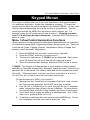
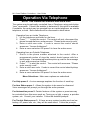
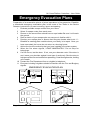
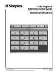
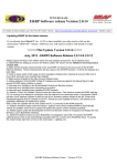
Emergency Evacuation Plans
Preparation of an evacuation plan Is of prime importance in fire prevention. Establish
a household emergency evacuation plan in the event of fire. Refer to the Smoke
Detector instructions (or exact mounting, layout and spacing.
1 Evaluate possible escape routes from your home.
2 Select 2 escape routes from each room.
3 Rooms on the second floor should have a rope ladder Be sure it will reach
the ground.
4 Draw a sketch of your escape plan so everyone is familiar with it.
5 Practice your escape plan to assure that everyone knows what to do. 6 Establish a meeting place outside where your family is to report. Once you
have evacuated, the house do not return to a burning house.
7 Advise the local fire authority that you have installed a fire alarm system.
8 When the fire alarm signals, LEAVE IMMEDIATELY. Do not stop for
belongings.
9 If a fire occurs, test the door. If hot, use your alternate route. If the door is
cool, brace your shoulder against it and open it cautiously. Shut the door to
help prevent the fire and smoke from spreading. Crawl through smoke, holding
your breath.
10 Contact the Fire Department from a neighbor’s telephone.
11 Everyone including neighbors should be familiar with the Fire and Burglary
signals.
EMERGENCY EVACUATION PLAN
KITCHEN
BATH
BEDROOM
BEDROOM
BEDROOM
LIVING
ROOM
BEDROOM
FAMILY
ROOM
HALL
DINING
ROOM
BATH
FIRST FLOOR
SECOND FLOOR
FRONT
Page 24
BACK
M1 Cross Platform Controllers - User Guide
System Testing
To assure the proper working order, it is recommended that the system be
tested once a week using the following procedure. CAUTION: If the system
Is monitored by a Central Monitoring Station, always contact them prior
to performing this test.
Secure all protected doors and windows.
1. Enter a valid User code.
2. The Armed and Exit lights will illuminate and the exit tone will start.
At the end of the exit delay the alarm system will be armed Away.
3. Trip the system by opening a protected window.
4. Confirm that the alarm sounding device (bell or siren) activates.
5. Disarm the system to silence the system and return to normal status.
To test the system while also testing the system standby battery:
1. Remove the AC transformer from the AC outlet. It may be necessary
to remove the restraining screw securing the transformer to the wall.
2. The keypad will display AC Trouble after a programmed time delay.
3. Activate the system using steps 1 to 7 listed above.
NOTE: Plug the AC transformer into the AC outlet after the test.
A manual battery load test may be activated without tripping the alarm.
1. Press the MENU key and enter a Master User Code.
2. Press the UP arrow key to find: “8-System Settings.”
3. To select this menu press the RIGHT arrow key.
4. Press the UP arrow key to find “84-System Test”.
5. To select this menu press the RIGHT arrow key. The Keypad will
display “1:Battery Test”.
6. To start the test press the RIGHT arrow key. The battery voltage and
current (amperage consumed by the system) will be displayed. The
battery is OK if it maintains a voltage above 12.2V for the test duration.
If a LOW BATTERY trouble occurs, the battery should be replaced.
Contact the installation company for service.
This control unit was manufactured under rigid quality standards. Maintenance is best performed by the installing company with trained service
personnel.
Page 25
M1 Cross Platform Controllers - User Guide
FCC Statements (Part 15 & 68)
The Ness-M1 complies with Part 68 of the FCC rules. On the front nameplate of the main control
board is a label that contains, among other information, the FCC certification number and ringer
equivalence number (REN) for this equipment. If requested, this information must be provided to
the telephone company. This equipment uses a “Mode 3” connection to connect to the telephone
network. The REN is used to determine the quantity of devices that may be connected to the
telephone line. Excessive REN’s on the telephone line may result in the devices not ringing in
response to an incoming call. Typically, the sum of REN’s should not exceed five (5.0). To be
certain of the number of devices that may be connected to a line (as determined by the total
RENs) contact the local telephone company.
If the Ness-M1 equipment causes harm to the telephone network, the telephone company will
notify you in advance that temporary discontinuance of service may be required. But if advance
notice isn’t practical, the telephone company will notify the customer as soon as possible.
The telephone company may make changes in its facilities, equipment, operations, or procedures
that could affect the operation of the equipment. If the trouble is causing harm to the telephone
network, the telephone company may request you remove the equipment from the network until
the problem is resolved.
There are no user serviceable components in this product. All necessary repairs must be made by the
manufacturer. This equipment cannot be used on telephone company-provided coin service. Connection
to Party Line Service is subject to state tariffs. This equipment is hearing-aid compatible.
The Ness-M1 complies with Part 15 of FCC Rules which are designed to provide reasonable protection
against such interference in a residential installation. The FCC requires the following statement for your
information:
This equipment generates and uses radio frequency energy and if not installed and used properly, that
is, in strict accordance with the manufacturer’s instructions, may cause Interference to radio and television
reception. It has been type tested. However, there is no guarantee that interference will not occur in a
particular installation. If this equipment does cause interference to radio or television reception, which
can be determined by turning the equipment off and on, the user is encouraged to try to correct the
interference by one or more of the following measures:
* If using an indoor antenna, have a quality outdoor antenna installed.
* Reorient the receiving antenna until interference is induced or eliminated.
* Move the receiver away from the security control.
* Move the antenna leads away from any wire runs to the security control
* Have the security control plugged into a different outlet so that it and the receiver are on
different branch circuits.
If necessary, consult the dealer or an experienced radio/television technician for additional suggestions.
The user shall not make any changes or modifications to the equipment unless authorised by the
Installation Instructions or Users Manual. Unauthorized changes or modifications could void the
user’s authority to operate the equipment.
Page 26
M1 Cross Platform Controllers - User Guide
Glossary
Area (Partition): A room or section of a building having at least one Keypad
and one or more zones components. Components assigned to one
area are separated and independently controllable from components
assigned to other areas. For example: Only area 1 keypads can disarm
or arm area 1 zones.
Automation Functions: A keypad menu which allows the user to control
lights, relays, tasks, etc. with the touch of a button.
Bypass: A process which allows a zone to be temporarily excluded from
being monitored or detected by the control.
Central Monitoring Station: Location where alarm reports are transmitted.
Chime: An audible alert used to indicate when a zone is violated. The alert
can be a tone, voice, or both. Zones are selectable.
Duress Code: A special user code that can be used to disarm the system
while silently reporting an alarm signal to the Central Monitoring Station.
Event Log: A record of recent activity by the system. Arms, disarms,
alarms, access, troubles, etc. can be viewed with the date and time the
occurred.
User Code: A four or six digit number that is sometimes required to identify
and authorize a person (User) to operate the system.
Zone: Generally consists of a single element such as a door, window,
motion detector, etc. of the system, making it possible to isolate a
trouble or alarm condition for reporting and troubleshooting purposes.
Page 27
www.ness.com.au
email : [email protected]