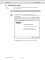
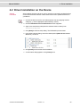
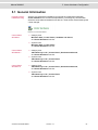
1
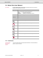
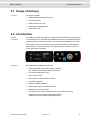
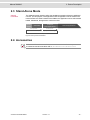
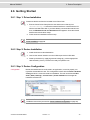
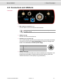
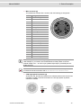
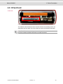
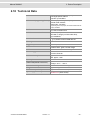
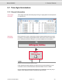
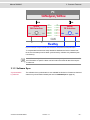
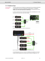
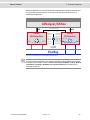
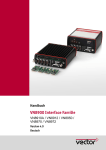
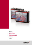
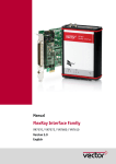
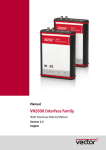
Manual
VN8810
Wireless Interface for CAN/LIN/K-Line and DoIP
Version 1.1
English
Imprint
Vector Informatik GmbH
Ingersheimer Straße 24
D-70499 Stuttgart
The information and data given in this user manual can be changed without prior notice. No part of this manual may be reproduced in any
form or by any means without the written permission of the publisher, regardless of which method or which instruments, electronic or
mechanical, are used. All technical information, drafts, etc. are liable to law of copyright protection.
© Copyright 2015, Vector Informatik GmbH. All rights reserved.
Manual VN8810
Contents
Contents
1 Introduction
5
1.1 Safety Instructions and Hazard Warnings
6
1.1.1 Proper Use and Intended Purpose
6
1.1.2 Hazards
7
1.1.3 Disclaimer
7
1.2 About this User Manual
8
1.2.1 Certification
8
1.2.2 Warranty
9
1.2.3 Registered Trademarks
9
2 Device Description
10
2.1 Scope of Delivery
11
2.2 Introduction
11
2.3 Stand-Alone Mode
12
2.4 Accessories
12
2.5 Examples of Usage
13
2.5.1 Flash Reprogramming
13
2.6 Getting Started
14
2.6.1 Step 1: Driver Installation
14
2.6.2 Step 2: Device Installation
14
2.6.3 Step 3: Device Configuration
14
2.6.4 Step 4: WiFi/ETH Configuration
15
2.7 User Interface
16
2.8 Connectors and CANterm
17
2.9 CFast Card
19
2.10 Technical Data
20
3 Common Features
21
3.1 Time Synchronization
22
3.1.1 General Information
22
3.1.2 Software Sync
23
3.1.3 Hardware Sync
24
4 Driver Installation
26
4.1 Vector Driver Setup
27
4.2 Driver Installation on the Device
29
© Vector Informatik GmbH
Version 1.1
-3-
Manual VN8810
Contents
5 Vector Hardware Configuration
30
5.1 General Information
31
5.2 Tool Description
32
5.2.1 Introduction
32
5.2.2 Tree View
33
© Vector Informatik GmbH
Version 1.1
-4-
Manual VN8810
1 Introduction
1 Introduction
In this chapter you find the following information:
1.1 Safety Instructions and Hazard Warnings
6
1.1.1 Proper Use and Intended Purpose
6
1.1.2 Hazards
7
1.1.3 Disclaimer
7
1.2 About this User Manual
8
1.2.1 Certification
8
1.2.2 Warranty
9
1.2.3 Registered Trademarks
9
© Vector Informatik GmbH
Version 1.1
-5-
Manual VN8810
1 Introduction
1.1 Safety Instructions and Hazard Warnings
!
Caution: In order to avoid personal injuries and damage to property, you have to read
and understand the following safety instructions and hazard warnings prior to installation and use of this interface. Keep this documentation (manual) always near the
interface.
1.1.1 Proper Use and Intended Purpose
!
Caution: The interface is designed for analyzing, controlling and otherwise influencing control systems and electronic control units. This includes, inter alia, bus systems like CAN, LIN, K- Line, MOST, FlexRay, Ethernet, BroadR- Reach and/or
ARINC 429.
The interface may only be operated in a closed state. In particular, printed circuits
must not be visible. The interface may only be operated (i) according to the instructions and descriptions of this manual; (ii) with the electric power supply designed for
the interface, e.g. USB- powered power supply; and (iii) with accessories manufactured or approved by Vector.
The interface is exclusively designed for use by skilled personnel as its operation
may result in serious personal injuries and damage to property. Therefore, only those
persons may operate the interface who (i) have understood the possible effects of
the actions which may be caused by the interface; (ii) are specifically trained in the
handling with the interface, bus systems and the system intended to be influenced;
and (iii) have sufficient experience in using the interface safely.
The knowledge necessary for the operation of the interface can be acquired in workshops and internal or external seminars offered by Vector. Additional and interface
specific information, such as „Known Issues“, are available in the „Vector KnowledgeBase“ on Vector´s website at www.vector.com. Please consult the „Vector
KnowledgeBase“ for updated information prior to the operation of the interface.
© Vector Informatik GmbH
Version 1.1
-6-
Manual VN8810
1 Introduction
1.1.2 Hazards
!
Caution: The interface may control and/or otherwise influence the behavior of control
systems and electronic control units. Serious hazards for life, body and property may
arise, in particular, without limitation, by interventions in safety relevant systems
(e.g. by deactivating or otherwise manipulating the engine management, steering,
airbag and/or braking system) and/or if the interface is operated in public areas (e.g.
public traffic, airspace). Therefore, you must always ensure that the interface is used
in a safe manner. This includes, inter alia, the ability to put the system in which the
interface is used into a safe state at any time (e.g. by „emergency shutdown“), in particular, without limitation, in the event of errors or hazards.
Comply with all safety standards and public regulations which are relevant for the
operation of the system. Before you operate the system in public areas, it should be
tested on a site which is not accessible to the public and specifically prepared for performing test drives in order to reduce hazards.
1.1.3 Disclaimer
!
Caution: Claims based on defects and liability claims against Vector are excluded to
the extent damages or errors are caused by improper use of the interface or use not
according to its intended purpose. The same applies to damages or errors arising
from insufficient training or lack of experience of personnel using the interface.
© Vector Informatik GmbH
Version 1.1
-7-
Manual VN8810
1 Introduction
1.2 About this User Manual
Conventions
In the two following charts you will find the conventions used in the user manual
regarding utilized spellings and symbols.
Style
bold
Utilization
Blocks, surface elements, window- and dialog names of the software. Accentuation of warnings and advices.
[OK]
Push buttons in brackets
File|Save
Notation for menus and menu entries
Microsoft
Legally protected proper names and side notes.
Source Code
Hyperlink
<CTRL>+<S>
File name and source code.
Hyperlinks and references.
Notation for shortcuts.
Symbol
Utilization
Here you can obtain supplemental information.
!
This symbol calls your attention to warnings.
Here you can find additional information.
Here is an example that has been prepared for you.
Step-by-step instructions provide assistance at these points.
Instructions on editing files are found at these points.
This symbol warns you not to edit the specified file.
1.2.1 Certification
Certified Quality
Management
System
© Vector Informatik GmbH
Vector Informatik GmbH has ISO 9001:2008 certification. The ISO standard is a
globally recognized standard.
Version 1.1
-8-
Manual VN8810
1 Introduction
1.2.2 Warranty
Restriction
of warranty
We reserve the right to change the contents of the documentation and the software
without notice. Vector Informatik GmbH assumes no liability for correct contents or
damages which are resulted from the usage of the documentation. We are grateful
for references to mistakes or for suggestions for improvement to be able to offer you
even more efficient products in the future.
1.2.3 Registered Trademarks
Registered
trademarks
All trademarks mentioned in this documentation and if necessary third party
registered are absolutely subject to the conditions of each valid label right and the
rights of particular registered proprietor. All trademarks, trade names or company
names are or can be trademarks or registered trademarks of their particular proprietors. All rights which are not expressly allowed are reserved. If an explicit label of
trademarks, which are used in this documentation, fails, should not mean that a
name is free of third party rights.
> Windows, Windows 7, Windows 8.1
are trademarks of the Microsoft Corporation.
© Vector Informatik GmbH
Version 1.1
-9-
Manual VN8810
2 Device Description
2 Device Description
In this chapter you find the following information:
2.1 Scope of Delivery
11
2.2 Introduction
11
2.3 Stand-Alone Mode
12
2.4 Accessories
12
2.5 Examples of Usage
13
2.5.1 Flash Reprogramming
13
2.6 Getting Started
14
2.6.1 Step 1: Driver Installation
14
2.6.2 Step 2: Device Installation
14
2.6.3 Step 3: Device Configuration
14
2.6.4 Step 4: WiFi/ETH Configuration
15
2.7 User Interface
16
2.8 Connectors and CANterm
17
2.9 CFast Card
19
2.10 Technical Data
20
© Vector Informatik GmbH
Version 1.1
- 10 -
Manual VN8810
2 Device Description
2.1 Scope of Delivery
Contents
The delivery includes:
> VN8810 Intelligent Diagnostic Device
> WiFi Antenna (2x)
> USB3.0 cable (A-B, 1.8 m)
> VN8800 Device Manager CD
> Quick Start Guide
2.2 Introduction
General
information
The VN8810 is a network interface for CAN/LIN/K-Line as well as DoIP (Diagnostics
over Internet Protocol). It enables the standalone execution of applications like reprogramming of ECUs, execution of scripts or remote access for diagnostic use cases.
Connectivity options to the infrastructure are provided by Ethernet, USB and WiFi
(802.11 a/b/g/n, 2.4 GHz and 5 GHz). One single and robust connector is used to
access the vehicles via OBD-II.
Figure 1: Front and back side of the VN8810
Highlights
Main features of the VN8810 interface are:
> CAN High-Speed channel with support of CAN FD
incl. internal and switchable CANterm (120 Ohm)
> LIN channel (supporting K-Line)
> DoIP Activation Line
> Bicolor LEDs for status and bus activities
> Key pad for operation
> Buzzer for audible feedback
> USB3.0 host connector for 3G/4G devices
> Hardware time synchronization
of multiple Vector network interfaces (CAN, LIN, FlexRay, Ethernet)
> Robustness, power supply and temperature ranges
suitable for automotive and industrial applications
© Vector Informatik GmbH
Version 1.1
- 11 -
Manual VN8810
2 Device Description
2.3 Stand-Alone Mode
General
information
The VN8810 network interface offers the standalone operation without any additional
user PC. For this purpose, user applications and configurations can be stored on the
internal CFast card. After a restart of the VN8810, the application can be selected and
loaded. Afterwards, the application can be executed.
power/
restart
start time
start-up time
(see technical data)
load and
start application
execute application
loading time
(depends on config)
total boot-up time
Figure 2: Boot-up time of the VN8810
2.4 Accessories
Reference: Information on available accessories can be found in the separate
accessories manual on the driver CD in \Documentation\Accessories.
© Vector Informatik GmbH
Version 1.1
- 12 -
Manual VN8810
2 Device Description
2.5 Examples of Usage
2.5.1 Flash Reprogramming
Description
One major use case of the VN8810 is standalone flash reprogramming. In this setup,
the flash packages (containing flash configuration and flash data) are stored on the
CFast card inside the VN8810. When the VN8810 is connected to the vehicle with an
appropriate OBD cable, the flash reprogramming can be executed on the device.
Alternatively, the flash reprogramming can be executed and monitored through a
mobile device.
Setup
PC
configure
DeviceUManagerU/U
ApplicationUgemUgmUvFlashf
transfer
flash packages
to VN8810
WiFi/USB/Ethernet
VN8810
storingU
flashUconfigUandUflashUdata
execute
VN8810
reprogramming
ECU
OBD
WiFi
execute and monitor
flash reprogramming
Mobile
Device
CAN/LIN/K.Line/ETHUgDoIPf
Vehicle
Figure 3: Flash reprogramming of vehicles
Reference: Please find further information on standalone applications in the related
manuals, e. g. vFlash user manual.
© Vector Informatik GmbH
Version 1.1
- 13 -
Manual VN8810
2 Device Description
2.6 Getting Started
2.6.1 Step 1: Driver Installation
Please use the drivers from the included Vector Driver Disk.
1. Execute Vector Driver Setup from the auto start menu or directly from
\Drivers\Setup.exe before the network interface is connected to the PC
with the included USB cable. If you have already connected the network interface, the Windows found new Hardware wizard appears. Close this wizard
and then execute the driver setup.
2. Finish the driver installation with the setup.
Reference: Further information on the driver installation can be found in section
Driver Installation on page 26.
2.6.2 Step 2: Device Installation
1. Install the drivers as described before.
2. Connect the network interface to a free USB3.0 port via the USB cable.
3. Power-up the device by supplying external voltage (e.g. with an appropriate
cable offered by Vector). The device is ready for operation now.
2.6.3 Step 3: Device Configuration
Configuration
Before the installed device can be used in an application, it must be properly configured for the needed use case. This configuration is done with the Vector Hardware
Config tool which comes with the driver installation. The tool can be found in Windows | Start | Settings | Control Panel | Vector Hardware and manages all
installed Vector devices.
Figure 4: Vector Hardware Config
Reference: Further details on the Vector Hardware Config tool can be found in the
installation instructions (see section Vector Hardware Configuration on page 30).
© Vector Informatik GmbH
Version 1.1
- 14 -
Manual VN8810
2 Device Description
2.6.4 Step 4: WiFi/ETH Configuration
Device Management The VN8810 needs to be configured for WiFi and Ethernet as well. This configuration
requires Vector Device Manager which is installed with your application (e. g. vFlash
Compact).
Reference: Further details on Vector Device Manager can be found in the related
user manual.
© Vector Informatik GmbH
Version 1.1
- 15 -
Manual VN8810
2 Device Description
2.7 User Interface
VN8810
user interface
Figure 5: Key pad and bicolor LEDs on the front side
Push buttons
> Start/Stop
Starts or stops measurement.
> Multi purpose
Application specific multi purpose key pad.
LED P1...P5
Color
Green, orange, red
Description
Application specific.
LED CAN
Color
Green
Red
Off
Description
Data frames have been sent or received correctly.
Flashing frequency depends on the data traffic.
Error frames have been sent or received.
Flashing frequency depends on the data traffic.
Bus off.
No data traffic.
LED K-Line / LIN
Color
Green
Orange
Red
Off
Description
Data frames have been sent or received correctly.
Data traffic with at least one error.
Error.
No data traffic.
LED ETH
Color
Green, orange, red
Description
Application specific information on link status and activity.
LED WiFi
Color
Green, orange, red
Description
Application specific information on link status and activity.
LED Status
Color
Green
Orange
Red
Off
Description
Device is ready for operation/running measurement.
Initializing or updating software. Please wait.
Error. Device not working.
Device off.
Orange
© Vector Informatik GmbH
Version 1.1
- 16 -
Manual VN8810
2 Device Description
2.8 Connectors and CANterm
Description
1
3
2
7
5
4
6
Figure 6: Connectors on the back side
> WiFi antenna connectors [1, 7]
Use both SMA connectors to attach the WiFi antennas.
Note: To keep conformity with international laws, use only antennas
provided by Vector!
> USB3.0 host [2]
Use this connector for 3G/4G devices.
> Hardware sync connector [3]
This connector (Binder type 711) can be used for time synchronization of different
Vector devices (see section Time Synchronization on page 22). The sync connector is not intended to connect a power supply.
Pin
1
2
3
Assignment
Not connected
Synchronization line
Ground
3
1
2
> USB3.0 device [4]
Connect your PC and the VN8810 via USB for installation and configuration. Use
the high-class and USB3.0 compliant cable found in the delivery (other USB
cables and extensions of lower quality may generate faults).
© Vector Informatik GmbH
Version 1.1
- 17 -
Manual VN8810
2 Device Description
> Main connector [5]
The VN8810 has a 22-pin ODU connector with the following pin assignment:
Pin
1
2
3
4
5
6
7
8
9
10
11
12
13
14
15
16
17
18
19
20
21
22
Assignment
Ethernet TX (-)
Reserved
Reserved
DoIP Act. Line
Chassis GND
Voltage Plus
CAN GND
CAN High
LIN GND
VBatt LIN
Not connected
Reserved
Reserved
Ethernet RX (-)
Ethernet TX (+)
Not connected
Chassis GND
Voltage Plus
CAN Low
LIN / K-Line
Not connected
Ethernet RX (+)
2
3
4
5
1
14
15 22
13
16
21
17
20
6
18 19
7
8
12
11
10
9
Note: LIN requires an external voltage supply which is directly provided by the OBDcable VN88(A). If you intend to use the Breakout Box VN88, please connect an
external voltage of 5 V…36 V DC to pin 9 (VBatt LIN) and pin 3 (LIN GND) at the DSUB9 connector.
Reference: Information on available accessories can be found in the separate
accessories manual on the driver CD in \Documentation\Accessories.
> CAN High-Speed Termination [6]
At the back side, the network interface has a CANterm selector that can be used
to disable or enable a 120 Ohm termination for CAN High-Speed. By default,
CANterm is enabled:
with
CANterm
© Vector Informatik GmbH
Version 1.1
without
CANterm
- 18 -
Manual VN8810
2 Device Description
2.9 CFast Card
CFast card
Figure 7: Opened VN8810 with inserted CFast card
The VN8810 is delivered with a CFast card which stores the operating system, the
applications and user data. This CFast card must not be removed during operation.
Note: The CFast card should only be removed for system recoveries. Please contact
the Vector support for further instructions on system recoveries.
© Vector Informatik GmbH
Version 1.1
- 19 -
Manual VN8810
2 Device Description
2.10 Technical Data
CAN channel
TJA1051 (capacitively decoupled),
CAN High-Speed: 2 Mbit/s
CAN FD: up to 8 Mbit/s
LIN channel (supporting K-Line) TLE7269 (capacitively decoupled),
Normal mode: 20 kbit/s
Flash mode: 115 kbit/s*
*Depending on the bus physics, the maximum data rate can
be up to 330 kbit/s.
DoIP
Fast Ethernet 100 Mbit
incl. DoIP Activation Line
PC/infrastructure interface
USB3.0 SuperSpeed
WiFi 802.11 a/b/g/n (2.4 GHz and 5 GHz),
up to 300 Mbit/s
Host interface
USB3.0 SuperSpeed,
e. g. to connect to 3G/4G USB devices
Memory
8 GB CFast card
Key pad
With two push buttons
Bicolor LED
Ten bicolor LEDs for status and bus activities,
possible colors: green, red and orange
CANterm
Switchable 120 Ohm terminating resistor
Power supply
6 V ... 36 V,
via main connector
Power consumption
Typ. < 9 W
Max. approx. 16 W
Start-up time
< 20 seconds
Temperature range
Operation: -40 °C ... +50 °C
(ambient temperature of the device)
Storage: -40 °C ... +85 °C
Relative humidity of ambient air 15 %...95 %, non-condensing
Weight
Approx. 800 g
Dimensions (LxWxH)
Approx. 170 x 110 x 45 mm (without antennas)
Operating system requirements Windows 7 (32 bit / 64 bit)
Windows 8.1 (32 bit / 64 bit)
© Vector Informatik GmbH
Version 1.1
- 20 -
Manual VN8810
3 Common Features
3 Common Features
In this chapter you find the following information:
3.1 Time Synchronization
22
3.1.1 General Information
22
3.1.2 Software Sync
23
3.1.3 Hardware Sync
24
© Vector Informatik GmbH
Version 1.1
- 21 -
Manual VN8810
3 Common Features
3.1 Time Synchronization
3.1.1 General Information
Time stamps
and events
Time stamps are useful when analyzing incoming or outgoing data or event sequences
on a specific bus.
Figure 8: Time stamps of two CAN channels in CANalyzer
Generating
time stamps
Each event which is sent or received by a Vector network interface has an accurate
time stamp. Time stamps are generated for each channel in the Vector network interface. The base for these time stamps is a common hardware clock in the device.
PC
CANalyzer/CANoe
USB
Vector
CAN Interface
Time Stamp Clock
CAN
CH1
CH2
Figure 9: Common time stamp clock for each channel
If the measurement setup requires more than one Vector network interface, a synchronization of all connected interfaces and their hardware clocks is needed.
Due to manufacturing and temperature tolerances, the hardware clocks may vary in
speed, so time stamps of various Vector devices drift over time.
© Vector Informatik GmbH
Version 1.1
- 22 -
Manual VN8810
3 Common Features
PC
CANalyzer/CANoe
USB
USB
Vector
CANzInterface
CH1
TimezStampzClock
CH2
sec
0.000000
0.100376
0.200382
0.300372
0.400406
0.500593
0.600242
sec
0.000000
0.100383
0.200982
0.301456
0.402612
0.503885
0.604092
Vector
FRzInterface
CHA
TimezStampzClock
CHB
CAN
FlexRay
Figure 10: Example of unsynchronized network interfaces. Independent time stamps drift apart
To compensate for these time stamp deviations between the Vector network interfaces, the time stamps can be either synchronized by software or by hardware (see
next section).
Note: The accuracy of the software and hardware sync depends on the interface. Further information on specific values can be found in the technical data of the respective devices.
3.1.2 Software Sync
Synchronization
by software
The software time synchronization is not available for this device. Please use the hardware time synchronization instead (see section Hardware Sync on page 24).
© Vector Informatik GmbH
Version 1.1
- 23 -
Manual VN8810
3 Common Features
3.1.3 Hardware Sync
Synchronization
by hardware
A more accurate time synchronization of multiple devices is provided by the hardware
synchronization which has to be supported by the application (e. g. CANalyzer,
CANoe). Two Vector network interfaces can therefore be connected with the SYNCcableXL (see accessories manual, part number 05018).
In order to synchronize up to five devices at the same time, a distribution box is available (see accessories manual, part number 05085).
Figure 11: Example of a time synchronization with multiple devices
Figure 12: Example of a time synchronization with VN8912 and additional devices
At each falling edge on the sync line which is initiated by the application, the Vector
network interface generates a time stamp that is provided to the application. This
© Vector Informatik GmbH
Version 1.1
- 24 -
Manual VN8810
3 Common Features
allows the application to calculate the deviations between the network interfaces and
to synchronize the time stamps to a common time base (master clock) which is
defined by the application.
CANalyzer/CANoe
USB
Vector
CANMInterface
CH1
TimeMStampMClockM
CH2
synchronization
USB
byMhardwareM)SYNCcable1
sec
sec
0.000000
0.000000
Vector
1.100375
1.100376
FRMInterface
1.200382
1.200381
2.300372
2.300371
2.400406
2.400405
CHB
3.500593 CHA
3.500592
MasterMTimeMStampMClockM
3.600242
3.600241
CAN
FlexRay
Figure 13: Time stamps are synchronized to the master clock
Note: The hardware synchronization must be supported by the application. For further information please refer to the relevant application manual. Please note that the
software synchronization must be disabled (see Vector Hardware Config | General
information | Settings | Software time synchronization) if the hardware synchronization is used.
© Vector Informatik GmbH
Version 1.1
- 25 -
Manual VN8810
4 Driver Installation
4 Driver Installation
In this chapter you find the following information:
4.1 Vector Driver Setup
27
4.2 Driver Installation on the Device
29
© Vector Informatik GmbH
Version 1.1
- 26 -
Manual VN8810
4 Driver Installation
4.1 Vector Driver Setup
General
information
The Vector Driver Disk offers a driver setup which allows the installation or the
removal of Vector devices.
Note: Please note that you will need Administrator Rights for the following steps.
1. Execute the driver setup from the autostart menu or directly from
\Drivers\Setup.exe before the device is connected to the PC with the
included USB cable.
If you have already connected the device to the PC, the Windows found new
Hardware wizard appears. Close this wizard and then execute the driver setup.
2. Click [Next] in the driver setup dialog. The initialization process starts. © Vector Informatik GmbH
Version 1.1
- 27 -
Manual VN8810
4 Driver Installation
3. In the driver selection dialog, select your devices to be installed (or to be uninstalled).
4. Click [Install] to execute the driver installation, or [Uninstall] to remove existing
drivers.
5. A confirmation dialog appears. Click [Close] to exit.
After successful installation, the device is ready for operation and can be connected to the PC with the included USB cable and powered by supplying external
voltage (e. g. with an appropriate cable offered by Vector).
© Vector Informatik GmbH
Version 1.1
- 28 -
Manual VN8810
4 Driver Installation
4.2 Driver Installation on the Device
General
information
After installing the device driver on your PC we also recommend to update the driver
on the Vector network interface. Follow these instructions to update the drivers on
your device.
1. Connect the device to the PC via USB and power it up by supplying external
voltage (e. g. with an appropriate cable offered by Vector).
2. Close the Windows found new Hardware wizard if it appears.
3. Again, execute the driver setup from the autostart menu or directly from
\Drivers\Setup.exe.
4. Click [Next] in the driver setup dialog. The initialization process starts. 5. In the driver selection dialog, select the related option Update drivers on the
device for your device.
6. Click [Install] to execute the driver installation.
7. A confirmation dialog appears. Click [Close] to exit.
© Vector Informatik GmbH
Version 1.1
- 29 -
Manual VN8810
5 Vector Hardware Configuration
5 Vector Hardware Configuration
In this chapter you find the following information:
5.1 General Information
31
5.2 Tool Description
32
5.2.1 Introduction
32
5.2.2 Tree View
33
© Vector Informatik GmbH
Version 1.1
- 30 -
Manual VN8810
5 Vector Hardware Configuration
5.1 General Information
Executing Vector
Hardware Config
After the successful driver installation you will find the configuration application
Vector Hardware in the Control Panel (see below). The tool gives you information
about the connected and installed Vector devices. There are also several settings that
can be changed.
Figure 14: Icon in Control Panel
Control Panel
Windows 7
> Category view
Windows Start | Control Panel | Hardware and Sound,
click Vector Hardware in the list.
> Symbols view
Windows Start | Control Panel,
click Vector Hardware in the list.
Control Panel
Windows 8.1
> Category view
<Windows key>+<X> | Control Panel | Hardware and Sound,
click Vector Hardware in the list.
> Symbols view
<Windows key>+<X> | Control Panel,
click Vector Hardware in the list.
Control Panel
Windows 10
> Category view
<Windows key>+<X> | Control Panel | Hardware and Sound,
click Vector Hardware in the list.
> Symbols view
<Windows key>+<X> | Control Panel,
click Vector Hardware in the list.
© Vector Informatik GmbH
Version 1.1
- 31 -
Manual VN8810
5 Vector Hardware Configuration
5.2 Tool Description
5.2.1 Introduction
Vector
Hardware Config
Figure 15: General view of Vector Hardware Config
Logical and physical
channels
Vector Hardware Config enables the channel configuration between installed Vector
devices and applications. Applications use so-called logical channels which are hardware independent and have to be assigned to real hardware channels.
Application
logical channel
CAN 1
logical channel
LIN 1
logical channel
logical channel
FlexRay 1
CAN 1
logical channel
CAN 2
not assigned
physical CH1
CAN
physical CH2
LIN
Vector Device 1
physical CH1
FlexRay
physical CH2
CAN
Vector Device 2
Figure 16: Concept of channel assignments
Figure 17: Channel assignment in Vector Hardware Config
© Vector Informatik GmbH
Version 1.1
- 32 -
Manual VN8810
5 Vector Hardware Configuration
5.2.2 Tree View
Accessing
Vector devices
The tool is split into two windows. The left window has a tree view and lets you
access the installed Vector devices, the right window displays the details of the selection. The following nodes are available in the tree view:
Hardware
The Hardware section lists the installed Vector devices. Each device item has physical channels which can be assigned to any number of logical channels (e. g. CANalyzer CAN 1). A logical channel can be assigned to only one physical channel.
Figure 18: Hardware
Application
In Application, all available applications are displayed in a tree view. According to
each application, the assignments of logical and physical channels are displayed in
the right part of the window. If no assignment exists, the information Not assigned
appears. The assignment can be edited via a right-click. An optional description can
be entered in the text field.
Figure 19: Application
© Vector Informatik GmbH
Version 1.1
- 33 -
Manual VN8810
General information
5 Vector Hardware Configuration
General information contains overall information on Vector devices and applications,
e. g. software time synchronization, transmit queue size, configurations flags, the
number of virtual CAN devices or the driver status.
Figure 20: General information
License
The License section contains information on all current available licenses (Vector bus
devices, Vector License USB dongle devices).
Figure 21: License
Reference: You will find a detailed description of Vector Hardware Config in the
online help (Help | Contents).
© Vector Informatik GmbH
Version 1.1
- 34 -
Get more Information!
Visit our Website for:
> News
> Products
> Demo Software
> Support
> Training Classes
> Addresses
www.vector.com