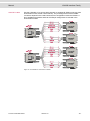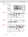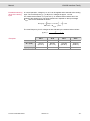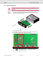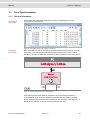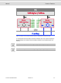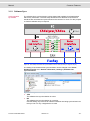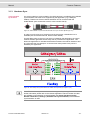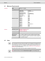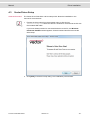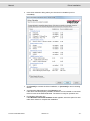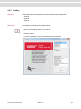
1
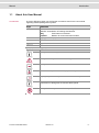
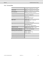
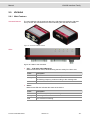
Manual VN1600 Interface Family VN1610 / VN1611 / VN1630A / VN1640A Version 2.0 English Imprint Vector Informatik GmbH Ingersheimer Straße 24 D-70499 Stuttgart The information and data given in this user manual can be changed without prior notice. No part of this manual may be reproduced in any form or by any means without the written permission of the publisher, regardless of which method or which instruments, electronic or mechanical, are used. All technical information, drafts, etc. are liable to law of copyright protection. Copyright 2013, Vector Informatik GmbH. Printed in Germany. All rights reserved. Manual Contents Contents 1 Introduction 3 1.1 About this User Manual 1.1.1 Certification 1.1.2 Warranty 1.1.3 Registered trademarks 4 5 5 5 2 VN1600 Interface Family 6 2.1 Introduction 7 2.2 Accessories 7 2.3 Getting Started 2.3.1 Step 1: Driver Installation 2.3.2 Step 2: Device Installation 2.3.3 Step 3: Device Configuration 2.3.4 Step 4: Quick Test 8 8 8 8 9 2.4 VN1610 2.4.1 2.4.2 2.4.3 2.4.4 Main Features Connectors Pin Assignment CH1 and CH2 Technical Data 10 10 10 11 11 VN1611 2.5.1 2.5.2 2.5.3 2.5.4 Main Features Connectors Pin Assignment CH1 and CH2 Technical Data 12 12 12 13 14 VN1630 2.6.1 2.6.2 2.6.3 2.6.4 2.6.5 2.6.6 2.6.7 2.6.8 Main Features Connectors Bus Side Connectors USB Side Bus Configuration Pin Assignment CH1/3 and CH2/4 Pin Assignment CH5 Replacing Piggybacks Technical Data 15 15 15 16 17 18 21 23 26 2.5 2.6 2.7 VN1630A 2.7.1 Main Features 27 27 2.8 VN1640 2.8.1 2.8.2 2.8.3 2.8.4 2.8.5 2.8.6 2.8.7 2.8.8 28 28 28 29 30 31 32 34 37 Main Features Connectors Bus Side Connectors USB Side Bus Configuration Pin Assignment CH1…CH4 Pin Assignment CH5 Replacing Piggybacks Technical Data 2.9 VN1640A 2.9.1 Main Features 38 38 3 Common Features 39 3.1 Time Synchronization 40 © Vector Informatik GmbH Version 2.0 -I- Manual VN1600 Interface Family 3.1.1 3.1.2 3.1.3 Contents General Information Software Sync Hardware Sync 40 42 43 4 Driver Installation 44 4.1 Minimum Requirements 45 4.2 Hints 45 4.3 Vector Driver Setup 46 4.4 Vector Hardware Configuration 48 4.5 Loop Tests 4.5.1 CAN 4.5.2 FlexRay 4.5.3 MOST 4.5.4 Ethernet 50 50 53 54 54 © Vector Informatik GmbH Version 2.0 - II - Manual Introduction 1 Introduction In this chapter you find the following information: 1.1 About this User Manual Certification Warranty Registered trademarks © Vector Informatik GmbH page 4 Version 2.0 -3- Manual 1.1 Introduction About this User Manual Conventions In the two following charts you will find the conventions used in the user manual regarding utilized spellings and symbols. Style Utilization bold Blocks, surface elements, window- and dialog names of the software. Accentuation of warnings and advices. [OK] Push buttons in brackets File|Save Notation for menus and menu entries Microsoft Legally protected proper names and side notes. Source Code File name and source code. Hyperlink Hyperlinks and references. <CTRL>+<S> Notation for shortcuts. Symbol Utilization Here you can obtain supplemental information. This symbol calls your attention to warnings. Here you can find additional information. Here is an example that has been prepared for you. Step-by-step instructions provide assistance at these points. Instructions on editing files are found at these points. This symbol warns you not to edit the specified file. © Vector Informatik GmbH Version 2.0 -4- Manual Introduction 1.1.1 Certification Certified Quality Vector Informatik GmbH has ISO 9001:2008 certification. The ISO standard is a Management System globally recognized standard. 1.1.2 Warranty Restriction of warranty We reserve the right to change the contents of the documentation and the software without notice. Vector Informatik GmbH assumes no liability for correct contents or damages which are resulted from the usage of the documentation. We are grateful for references to mistakes or for suggestions for improvement to be able to offer you even more efficient products in the future. 1.1.3 Registered trademarks Registered trademarks All trademarks mentioned in this documentation and if necessary third party registered are absolutely subject to the conditions of each valid label right and the rights of particular registered proprietor. All trademarks, trade names or company names are or can be trademarks or registered trademarks of their particular proprietors. All rights which are not expressly allowed are reserved. If an explicit label of trademarks, which are used in this documentation, fails, should not mean that a name is free of third party rights. > © Vector Informatik GmbH Windows, Windows XP, Windows Vista, Windows 7, Windows 8 are trademarks of the Microsoft Corporation. Version 2.0 -5- Manual VN1600 Interface Family 2 VN1600 Interface Family In this chapter you find the following information: 2.1 Introduction page 7 2.2 Accessories page 7 2.3 Getting Started page 8 2.4 VN1610 page 10 2.5 VN1611 page 12 2.6 VN1630 page 15 2.7 VN1630A page 27 2.8 VN1640 page 28 2.9 VN1640A page 38 © Vector Informatik GmbH Version 2.0 -6- Manual 2.1 VN1600 Interface Family Introduction General information The VN1600 interface family is an advanced development of the proven CANcaseXL which is a flexible and cost-efficient solution for CAN, LIN, K-Line or J1708 applications. An excellent performance with minimal latency times and high time stamp accuracy is also guaranteed. The multi-application functionality of the VN1600 interface family supports simultaneous operation of different applications on one channel, e. g. CANoe and CANape. Tasks range from simple bus analyses to complex remaining bus simulations as well as diagnostic, calibration and reprogramming tasks and also LIN 2.1 compliance tests. You can also program your own applications using the XL Driver Library. Bus types Depending on the VN16xx interface, built-in transceivers as well as exchangeable CAN/LIN and J1708 transceivers can be used. The exchangeable transceivers are available as plug-in boards (Piggybacks) and are inserted in the VN16xx. A list of compatible Piggybacks can be found in the accessories manual on the driver CD. Figure 1: Piggyback. 2.2 Accessories Reference: Further information on the available accessories can be found in the separate accessories manual on the driver CD in \Documentation\Accessories © Vector Informatik GmbH Version 2.0 -7- Manual 2.3 VN1600 Interface Family Getting Started 2.3.1 Step 1: Driver Installation Please use the drivers from the included Vector Driver Disk. 1. Execute Vector Driver Setup from the autostart menu or directly from \Drivers\Setup.exe before the VN16xx is connected to the PC over USB. If you have already connected the VN16xx, the Windows found new Hardware wizard appears. Close this wizard and then execute the driver setup. 2. Finish the driver installation with the setup. Note: Further information on the driver installation can be found in the separate installation instructions at the end of this manual. 2.3.2 Step 2: Device Installation 1. Install the drivers as described before. 2. Connect the VN16xx to a free USB2.0 port via the USB cable. 2.3.3 Step 3: Device Configuration Configuration Before the installed device can be used in an application (e. g. CANalyzer, CANoe), it has to be properly configured for the needed use case. This configuration is done with the Vector Hardware Config tool which comes with the driver installation. The tool can be found in: Windows | Start | Settings | Control Panel | Vector Hardware and manages all installed Vector devices. Figure 2: Vector Hardware Config. For the quick test described in this manual no further configuration is required. Note: Further details on the Vector Hardware Config tool can be found in the separate installation instructions at the end of this manual. © Vector Informatik GmbH Version 2.0 -8- Manual VN1600 Interface Family 2.3.4 Step 4: Quick Test Note: Please execute the test described in section Loop Tests on page 50. © Vector Informatik GmbH Version 2.0 -9- Manual 2.4 VN1600 Interface Family VN1610 2.4.1 Main Features VN1610 features The main features of the VN1610 interface are: > 2x CAN high-speed 1051cap transceivers (capacitively decoupled) > Software sync Figure 3: VN1610 CAN Interface. 2.4.2 Connectors > D-SUB9 (CH1/2) The VN1610 has a D-SUB9 connector with two CAN channels. Further information on the pin assignment for CH1/CH2 can be found in section Pin Assignment CH1 and CH2 on page 11. > USB Connect your PC and the VN1610 over USB to install and to use the device with measurement applications (e. g. CANoe, CANalyzer). © Vector Informatik GmbH Version 2.0 - 10 - Manual VN1600 Interface Family 2.4.3 Pin Assignment CH1 and CH2 D-SUB9 connector The pin assignment of the D-SUB9 connector (CH1 and CH2) is as follows: CH1/CH2 CAN Y cable Use the CANcable 2Y to access both channels on separate D-SUB9 connectors (see accessories manual, article number 05075). Figure 4: CANcable 2Y connected to VN1610. 2.4.4 Technical Data CAN channels 2x CAN high-speed 1051cap, up to 2 Mbit/s Temperature range Operating: -40 °C...+70 °C Shipping and storage: -40 °C...+85 °C Relative humidity of ambient air 15 %...95 %, non-condensing Operating system requirements Windows XP (SP3) Windows Vista (SP1) Windows 7 (32 Bit / 64 Bit) Windows 8 (64 Bit) Dimensions (LxWxH) 65 mm x 42 mm x 20 mm Weight 80 g © Vector Informatik GmbH Version 2.0 - 11 - Manual 2.5 VN1600 Interface Family VN1611 2.5.1 Main Features VN1611 features The main features of the VN1611 interface are: > 1x LIN 7269cap transceiver (capacitively decoupled) > 1x CAN high-speed 1051cap transceiver (capacitively decoupled) > Software sync Figure 5: VN1611 LIN/CAN Interface. Note: The VN1611 does not support LIN2.1 compliance tests. Please use the VN1630 or the VN1640 for these purposes. 2.5.2 Connectors > D-SUB9 (CH1/2) The VN1611 has a D-SUB9 connector with one LIN and one CAN channel. Further information on the pin assignment for CH1/CH2 can be found in section Pin Assignment CH1 and CH2 on page 13 > USB Connect your PC and the VN1611 over USB to install and to use the device with measurement applications (e. g. CANoe, CANalyzer). © Vector Informatik GmbH Version 2.0 - 12 - Manual VN1600 Interface Family 2.5.3 Pin Assignment CH1 and CH2 D-SUB9 connector The pin assignment of the D-SUB9 connector (CH1 and CH2) is as follows: CH1/CH2 Pdis: power disable CAN/LIN Y cable Use the CANcable 2Y to access both channels on separate D-SUB9 connectors (see accessories manual, article number 05075). Figure 6: CANcable 2Y connected to VN1611. Note: If pin 4 (Pdis) is connected to pin 3 (VB-), the internal power supply is disabled. In this case an external power supply is required at pin 9 (VB+). © Vector Informatik GmbH Version 2.0 - 13 - Manual VN1600 Interface Family 2.5.4 Technical Data CAN channels 1x CAN high-speed 1051cap, up to 2 Mbit/s LIN channels 1x LIN 7269cap, up to 330 kbit/s K-Line channels 1 Temperature range Operating: -40 °C...+70 °C Shipping and storage: -40 °C...+85 °C Relative humidity of ambient air 15 %...95 %, non-condensing Operating system requirements Windows XP (SP3) Windows Vista (SP1) Windows 7 (32 Bit / 64 Bit) Windows 8 (64 Bit) Dimensions (LxWxH) 65 mm x 42 mm x 20 mm Weight 80 g © Vector Informatik GmbH Version 2.0 - 14 - Manual 2.6 VN1600 Interface Family VN1630 2.6.1 Main Features VN1630 features The main features of the VN1630 interface are: > 2x CAN high-speed 1051cap transceivers (capacitively decoupled) > 2x additional plug-in locations for CAN/LINpiggies > Fifth channel for dedicated digital-analog input/output tasks > Software sync > Hardware sync (via SYNCcableXL) Figure 7: VN1630 CAN/LIN Interface. 2.6.2 Connectors Bus Side Device connectors Figure 8: VN1630 with 1x Sync and 2x D-SUB9. > Binder connector (Sync) This connector (Binder type 711) can be used for time synchronization of different Vector devices. The sync connector is not intended to connect a power supply. Pin Assignment © Vector Informatik GmbH 1 Not connected 2 Synchronization line 3 Ground Version 2.0 - 15 - Manual VN1600 Interface Family > D-SUB9 (CH1/3 and CH2/4) The VN1630 has two D-SUB9 connectors, each with up to two channels (CAN/CAN or LIN/CAN). Further information on the pin assignment for CH1/CH3 and CH2/CH4 can be found in section Pin Assignment CH1/3 and CH2/4 on page 18. 2.6.3 Connectors USB Side Device connectors Figure 9: VN1630 with 1x USB and 1x D-SUB9. > USB Connect your PC and the VN1630 over USB to install and to use the device with measurement applications (CANoe, CANalyzer). Use the USB2.0 compliant cable found in the delivery (USB extension cables may generate faults between the PC and the device). Connect the device directly to USB at your PC or use a USB hub with its own power supply (self-powered). Depending on the used Piggyback, the VN1630 requires the entire USB current (500 mA) which cannot be provided by a bus-powered USB hub. > D-SUB9 (CH5) The VN1630 has a D-SUB9 connector (CH5) for dedicated digital-analog input/output tasks. The pin assignment can be found in section Pin Assignment CH5 on page 21. © Vector Informatik GmbH Version 2.0 - 16 - Manual VN1600 Interface Family 2.6.4 Bus Configuration Piggybacks for CH1 and CH2 An advantage of the VN1630 is its two Piggyback plug-in locations (CH1 and CH2). Depending on requirements, electrically decoupled CAN High-Speed, CAN LowSpeed, CAN Single Wire, J1708 or LIN transceivers may be used. In addition, two electrically decoupled built-in CAN TJA1051 (high-speed) transceivers are available (CH3 and CH4). CH5 is reserved for dedicated IO tasks. Piggy 1 (CH1) Piggy 2 (CH2) Figure 10: Piggyback plug-in locations for CH1 and CH2. Plug-In Configuration Assignment Piggy 1 Piggy 2 CH1 CH2 CH3 CH4 CH5 X X Piggy 1 Piggy 2 1051cap 1051cap IO X O Piggy 1 1051cap 1051cap - IO O X 1051cap Piggy 2 - 1051cap IO O O 1051cap 1051cap - - IO X installed Piggyback O empty plug-in location 1051cap built-in transceiver channel not usable Note: If you intend to use only one LINpiggy, please use the first plug-in location (Piggy 1). Empty plug-in locations will be automatically loaded with a built-in transceiver. © Vector Informatik GmbH Version 2.0 - 17 - Manual VN1600 Interface Family 2.6.5 Pin Assignment CH1/3 and CH2/4 Double assignment of D-SUB9 connectors CH1 and CH2 Before installing a Piggyback in the plug-in location (see section Replacing Piggybacks on page 23), the pin assignment of the D-SUB9 connector (CH1/CH3 and CH2/CH4) has to be selected via DIP switches, which can be found inside the device at the plug-in locations. Piggy 1 (CH1/3) Piggy 2 (CH2/4) Figure 11: DIP switches (left: CH1/3, right: CH2/4). Pin assignment CH1 … CH4 The pin assignments of the D-SUB9 connectors depend on the used bus transceiver configuration inside the VN1630. A list of available Piggybacks and their D-SUB9 pin assignments is included in the separate accessories manual. A: all ‚OFF’ B: all ‚ON’ > No Piggyback inserted If no Piggyback is inserted, only the built-in CAN transceiver at CH1 (CH2) is active (no double assignment of the D-SUB9 connector): (1) (2) 1051cap CAN Low (3) 1051cap GND (4) (5) Shield (6) (7) 1051cap CAN High (8) (9) - Figure 12: Configuration without Piggyback. Example: No Piggyback The following example shows the pin assignment of CH1/CH3 if no Piggyback is inserted in the plug-in location 1. © Vector Informatik GmbH Version 2.0 - 18 - Manual VN1600 Interface Family > CAN/LIN Piggyback inserted If a CAN- or LINpiggy is inserted, the Piggyback is assigned to CH1 (CH2) and the built-in CAN transceiver is assigned to CH3 (CH4): (1) 1051cap CAN Low (2) Piggyback-dependent (3) Piggyback-dependent (4) Piggyback-dependent (5) Shield (6) 1051cap GND (7) Piggyback-dependent (8) 1051cap CAN High (9) Piggyback-dependent A: all ‚ON’ B: all ‚OFF’ Figure 13: Configuration with Piggyback. Example: CANpiggy 1041mag The following example shows the pin assignment of CH1/CH3 if a CANpiggy 1041mag is inserted in the plug-in location 1 (Piggy 1). Note: The described pin assignment is also valid for CH2/CH4. A warning message will appear in the Vector Hardware Config tool if the DIP switch settings are improperly set. Check your DIP switch settings in this case. © Vector Informatik GmbH Version 2.0 - 19 - Manual CAN/LIN Y cable VN1600 Interface Family Use the CANcable 2Y to access both channels on separate D-SUB9 connectors (see accessories manual, article number 05075). The pin assignments of the D-SUB9 connectors depend on the used bus transceiver configuration inside the VN1630. A list of available Piggybacks and their D-SUB9 pin assignments is included in the accessories manual. Figure 14: 2x CANcable 2Y connected to VN1630. © Vector Informatik GmbH Version 2.0 - 20 - Manual VN1600 Interface Family 2.6.6 Pin Assignment CH5 Digital/analog IO The pin assignment for CH5 is as follows: (1) Analog input (2) (3) (4) Digital input 0 (5) Digital input 1 (6) Analog GND (7) (8) Digital output (9) Digital GND Internal interconnection of digital input 0/1 Figure 15: Digital input 0/1. Internal interconnection of digital output Figure 16: Digital output. Internal interconnection of analog input Figure 17: Analog input. © Vector Informatik GmbH Version 2.0 - 21 - Manual Extended measuring range of the analog input VN1600 Interface Family In normal operation, voltages up to 18 V can be applied and measured at the analog input. The cutoff frequency (-3 dB) for AC voltages is approx. 7.2 kHz. For measurements above 18 V (max. 50 V), an external series resistor has to be applied to the analog input. The series resistor depends on the input voltage and can be calculated as follows: [ ] [( ) ] with The cutoff frequency for AC voltages is also affected by the external series resistor: [ Examples © Vector Informatik GmbH ] [ ] 24 V 32 V 36 V 48 V 367 k 856 k 1100 k 1833 k (E96) 374 k (24.12 V) 866 k (32.17 V) 1100 k (36.00 V) 1870 k (48.60 V) (-3 dB) 1148 Hz 496 Hz 390 Hz 230 Hz Version 2.0 - 22 - Manual VN1600 Interface Family 2.6.7 Replacing Piggybacks Warning: When performing this operation be sure not to touch the top or bottom of the boards (VN1630 main board or Piggybacks) to avoid damages due to electrical discharges. 1. First, loosen the VN1630 housing screws on the side with the two D-SUB9 connectors. This requires removing the two black decorative caps. Then carefully pull the PC-board out of the housing. Figure 18: Opening the housing. 2. You will find the plug-in location 1 (Channel 1) at the sync connector side and plug-in location 2 (Channel 2) at the edge of the PC-board. Piggy 1 CH1 Piggy 2 CH2 Figure 19: Piggyback plug-in locations CH1 and CH2. © Vector Informatik GmbH Version 2.0 - 23 - Manual VN1600 Interface Family 3. Each of the two Piggybacks is fastened by a screw and retainer. Please loosen the appropriate screw including the retainer and carefully remove the Piggyback from the plug-in location. CH1 CH2 Figure 20: Unmount/mount Piggybacks. 4. Set the DIP switches as described in section Pin Assignment CH1/3 and CH2/4 on page 18. 5. Insert the replacement Piggyback. When doing this please make sure that the single and dual-row connectors are not laterally offset. 6. Secure the new Piggyback with the appropriate screw and retainer. © Vector Informatik GmbH Version 2.0 - 24 - Manual VN1600 Interface Family 7. Place the VN1630 main board back in the housing. This operation involves placing the housing on a table with its back side (side with the bar code) facing upward. Then the main board with the Piggybacks facing upward is inserted into the second guide rails. Figure 21: Second guide rails. 8. It should be possible to slide the main board in the housing up to a few millimeters from the end without forcing it in. Close the housing by applying light pressure and then secure it with the appropriate screw fasteners. The screws should be secure but not excessively tight. 9. Please also attach the two black decorative caps. 10. Connect the VN1630 and the PC with the USB cable and check the bus configuration in Vector Hardware Config. Figure 22: Check inserted Piggybacks. © Vector Informatik GmbH Version 2.0 - 25 - Manual VN1600 Interface Family 2.6.8 Technical Data CAN channels Max. 4, configurable via Piggybacks, up to 2 Mbit/s LIN channels Max. 2, configurable via Piggybacks, up to 330 kbit/s K-Line channels Max. 2 with LINpiggy 7269mag at CH1/CH2 J1708 channels Max. 2, configurable via Piggybacks Analog input 10 bit Input 0...18 V Voltage tolerance up to 32 V Sampling rate up to 1 kHz Digital input Range 0...32 V Schmitt trigger high 2.7 V, low 2.2 V Hysteresis 0.5 V Input frequencies up to 1 kHz Digital output Open Drain External supply up to 32 V Current max. 500 mA Short circuit / over voltage protected Temperature range Operating: -40 °C...+70 °C Shipping and storage: -40 °C...+85 °C Relative humidity of ambient air 15 %...95 %, non-condensing Operating system requirements Windows XP (SP3) Windows Vista (SP1) Windows 7 (32 Bit / 64 Bit) Windows 8 (64 Bit) Dimensions (LxWxH) Approx. 85 mm x 106 mm x 32 mm Weight 230 g (without accessories) Power consumption Approx. 2.5 W © Vector Informatik GmbH Version 2.0 - 26 - Manual 2.7 VN1600 Interface Family VN1630A 2.7.1 Main Features VN1630A features The main features and the technical data of the VN1630A are identical to VN1630. On top of that, the VN1630A has five LEDs indicating bus activities and status. Figure 23: VN1630A CAN/LIN Interface. LEDs Figure 24: LEDs of the VN1630A. > > © Vector Informatik GmbH CH1 … CH4 (with CAN-/LINpiggies) Multicolored channel LEDs, each indicating the bus activity for CAN or LIN. Color Description Green Rx/Tx Data frames have been correctly sent or received. Orange Rx/Tx Error frames have been sent or received. The flashing frequency varies according to the message rate. Red Bus off. Status Multicolored LED that indicates the status of the device. Color Description Green Device is ready for operation/running measurement. Orange Initializing driver. Please wait. Red Error. Device not working. Version 2.0 - 27 - Manual 2.8 VN1600 Interface Family VN1640 2.8.1 Main Features VN1640 features The main features of the VN1640 interface are: > 4x plug-in locations for CAN/LINpiggies > Fifth channel for dedicated digital-analog input/output tasks > 5x D-SUB9 connectors > Software sync > Hardware sync (via SYNCcableXL) Figure 25: VN1640 CAN/LIN Interface. 2.8.2 Connectors Bus Side Device connectors Figure 26: VN1640 with 1x Sync and 4x D-SUB9. > © Vector Informatik GmbH Binder connector (Sync) This connector (Binder type 711) can be used for time synchronization of different Vector devices. The sync connector is not intended to connect a power supply. Version 2.0 - 28 - Manual VN1600 Interface Family Pin Assignment > 1 Not connected 2 Synchronization line 3 Ground D-SUB9 (CH1…CH4) The VN1640 has four D-SUB9 connectors, each assigned to a dedicated Piggyback plug-in location. Further information on the pin assignment can be found in section Pin Assignment CH1…CH4 on page 31. 2.8.3 Connectors USB Side Device connectors Figure 27: VN1640 with 1x USB and 1x D-SUB9. > USB Connect your PC and the VN1640 over USB to install and to use the device with measurement applications (CANoe, CANalyzer). Use the USB2.0 compliant cable found in the delivery (USB extension cables may generate faults between the PC and the device). Connect the device directly to USB at your PC or use a USB hub with its own power supply (self-powered). Depending on the used Piggyback, the VN1640 requires the entire USB current (500 mA) which cannot be provided by a bus-powered USB hub. > D-SUB9 (CH5) The VN1640 has a D-SUB9 connector (CH5) for dedicated digital-analog input/output tasks. The pin assignment can be found in section Pin Assignment CH5 on page 32. © Vector Informatik GmbH Version 2.0 - 29 - Manual VN1600 Interface Family 2.8.4 Bus Configuration Piggybacks An advantage of the VN1640 is its four Piggyback plug-in locations (CH1…CH4). Depending on requirements, electrically decoupled CAN High-Speed, CAN LowSpeed, CAN Single Wire, J1708 or LIN transceivers may be used. CH5 is reserved for dedicated IO tasks. Piggy 3 (CH3) Piggy 4 (CH4) Piggy 1 (CH1) Piggy 2 (CH2) Figure 28: Piggyback plug-in locations for CH1…CH4. Note: LINpiggies have to be inserted before CANpiggies (in ascending order). If you intend to use only one LINpiggy, please use the first plug-in location (CH 1). J1708 should be handled like CAN here. Piggyback Configurations © Vector Informatik GmbH Piggyback 1 CH1 Piggyback 2 CH2 Piggyback 3 CH3 Piggyback 4 CH4 CAN CAN CAN CAN LIN CAN CAN CAN LIN LIN CAN CAN LIN LIN LIN CAN LIN LIN LIN LIN Version 2.0 - 30 - Manual Further examples VN1600 Interface Family The following tables show examples of other combinations: 1x CAN 1x LIN 1x LIN 1x CAN 1x LIN 1x CAN 2x LIN 1x CAN CH1 CH2 CH3 CH4 CAN - - - CH1 CH2 CH3 CH4 LIN - - - CH1 CH2 CH3 CH4 LIN CAN - - CH1 CH2 CH3 CH4 - LIN - CAN CH1 CH2 CH3 CH4 LIN LIN CAN - 2.8.5 Pin Assignment CH1…CH4 Assignment of the D-SUB9 connectors The pin assignments depend on the inserted Piggybacks. A list of available Piggybacks and their D-SUB9 pin assignments can be found in the separate accessories manual on the driver CD in \Documentation\Accessories Example: CANpiggy 1041mag The following example shows the pin assignment of CH1 if a CANpiggy 1041mag is inserted in the plug-in location 1: © Vector Informatik GmbH Version 2.0 - 31 - Manual VN1600 Interface Family 2.8.6 Pin Assignment CH5 Digital/analog IO The pin assignment for CH5 is as follows: (1) Analog input (2) (3) (4) Digital input 0 (5) Digital input 1 (6) Analog GND (7) (8) Digital output (9) Digital GND Internal interconnection of digital input 0/1 Figure 29: Digital input 0/1. Internal interconnection of digital output Figure 30: Digital output. Internal interconnection of analog input Figure 31: Analog input. © Vector Informatik GmbH Version 2.0 - 32 - Manual Extended measuring range of the analog input VN1600 Interface Family In normal operation, voltages up to 18 V can be applied and measured at the analog input. The cutoff frequency (-3 dB) for AC voltages is approx. 7.2 kHz. For measurements above 18 V (max. 50 V), an external series resistor has to be applied to the analog input. The series resistor depends on the input voltage and can be calculated as follows: [ ] [( ) ] with The cutoff frequency for AC voltages is also affected by the external series resistor: [ Examples © Vector Informatik GmbH ] [ ] 24 V 32 V 36 V 48 V 367 k 856 k 1100 k 1833 k (E96) 374 k (24.12 V) 866 k (32.17 V) 1100 k (36.00 V) 1870 k (48.60 V) (-3 dB) 1148 Hz 496 Hz 390 Hz 230 Hz Version 2.0 - 33 - Manual VN1600 Interface Family 2.8.7 Replacing Piggybacks Warning: When performing this operation be sure not to touch the top or bottom of the boards (VN1640 main board or Piggybacks) to avoid damages due to electrical discharges. 1. First, loosen the VN1640 housing screws on the side with the four D-SUB9 connectors. This requires removing the two black decorative caps. Then carefully pull the PC-board out of the housing. Figure 32: Opening the housing. 2. The plug-in locations are defined as follows: Piggy 3 (CH3) Piggy 1 (CH1) Piggy 4 (CH4) Piggy 2 (CH2) Figure 33: Piggyback plug-in locations CH1…CH4. © Vector Informatik GmbH Version 2.0 - 34 - Manual VN1600 Interface Family 3. Each of the two Piggybacks is fastened by a screw and retainer. Please loosen the appropriate screw including the retainer and carefully remove the Piggyback from the plug-in location. CH1 CH3 CH2 CH4 Figure 34: Unmount/mount Piggybacks. 4. Insert the replacement Piggyback. When doing this please make sure that the single and dual-row connectors are not laterally offset. 5. Secure the new Piggyback with the appropriate screw and retainer. © Vector Informatik GmbH Version 2.0 - 35 - Manual VN1600 Interface Family 6. Place the VN1640 main board back in the housing. This operation involves placing the housing on a table with its back side (side with the bar code) facing upward. Then the main board with the Piggybacks facing upward is inserted into the first guide rails. Figure 35: First guide rails. 7. It should be possible to slide the main board in the housing up to a few millimeters from the end without forcing it in. Close the housing by applying light pressure and then secure it with the appropriate screw fasteners. The screws should be secure but not excessively tight. 8. Please also attach the two black decorative caps. 9. Connect the VN1640 and the PC with the USB cable and check the bus configuration in Vector Hardware Config. Figure 36: Check inserted Piggybacks. © Vector Informatik GmbH Version 2.0 - 36 - Manual VN1600 Interface Family 2.8.8 Technical Data CAN channels Max. 4, configurable via Piggybacks, up to 2 Mbit/s LIN channels Max. 4, configurable via Piggybacks, up to 330 kbit/s K-Line channels Max. 2 with LINpiggy 7269mag at CH1/CH2 J1708 channels Max. 4, configurable via Piggybacks Analog input 10 bit Input 0...18 V Voltage tolerance up to 32 V Sampling rate up to 1 kHz Digital input Range 0...32 V Schmitt trigger high 2.7 V, low 2.2 V Hysteresis 0.5 V Input frequencies up to 1 kHz Digital output Open Drain External supply up to 32 V Current max. 500 mA Short circuit / over voltage protected Temperature range Operating: -40 °C...+70 °C Shipping and storage: -40 °C...+85 °C Relative humidity of ambient air 15 %...95 %, non-condensing Operating system requirements Windows XP (SP3) Windows Vista (SP1) Windows 7 (32 Bit / 64 Bit) Windows 8 (64 Bit) Dimensions (LxWxH) Approx. 83 mm x 110 mm x 44 mm Weight 330 g (without accessories) Power consumption Approx. 2.5 W © Vector Informatik GmbH Version 2.0 - 37 - Manual 2.9 VN1600 Interface Family VN1640A 2.9.1 Main Features VN1640A features The main features and the technical data of the VN1640A are identical to VN1640. On top of that, the VN1640A has five LEDs indicating bus activities and status. Figure 37: VN1640A CAN/LIN Interface. LEDs Figure 38: LEDs of the VN1640A. > > © Vector Informatik GmbH CH1 … CH4 (with CAN-/LINpiggies) Multicolored channel LEDs, each indicating the bus activity for CAN or LIN. Color Description Green Rx/Tx Data frames have been correctly sent or received. Orange Rx/Tx Error frames have been sent or received. The flashing frequency varies according to the message rate. Red Bus off. Status Multicolored LED that indicates the status of the device. Color Description Green Device is ready for operation/running measurement. Orange Initializing driver. Please wait. Red Error. Device not working. Version 2.0 - 38 - Manual Common Features 3 Common Features In this chapter you find the following information: 3.1 Time Synchronization General Information Software Sync Hardware Sync © Vector Informatik GmbH page 40 Version 2.0 - 39 - Manual 3.1 Common Features Time Synchronization 3.1.1 General Information Time stamps and events Time stamps are useful when analyzing incoming or outgoing data or event sequences on a specific bus. Figure 39: Time stamps of two CAN channels in CANalyzer. Generating time stamps Each event which is sent or received by a Vector network interface has an accurate time stamp. Time stamps are generated for each channel in the Vector network interface. The base for these time stamps is a common hardware clock in the device. Figure 40: Common time stamp clock for each channel. If the measurement setup requires more than one Vector network interface, a synchronization of all connected interfaces and their hardware clocks is needed. Due to manufacturing and temperature tolerances, the hardware clocks may vary in speed, so time stamps of various Vector devices drift over time. © Vector Informatik GmbH Version 2.0 - 40 - Manual Common Features Figure 41: Example of unsynchronized network interfaces. Independent time stamps drift apart. To compensate these time stamp deviations between the Vector network interfaces, the time stamps can be either synchronized by software or by hardware (see next section). Note: The accuracy of the software sync is typically in range of 100 µs. Note: The accuracy of the hardware sync is typically in range of 1 µs. © Vector Informatik GmbH Version 2.0 - 41 - Manual Common Features 3.1.2 Software Sync Synchronization by software The software time synchronization is driver-based and available for all applications without any restrictions. The time stamp deviations from different Vector network interfaces are calculated and synchronized to the common PC clock. For this purpose no further hardware setup is required. Figure 42: Time stamps of devices are synchronized to the PC clock (accuracy in range of 100 µs). The setting of the software time synchronization can be changed in the Vector Hardware Config tool in General information | Settings | Software time synchronization. Figure 43: Switching on the software synchronization. > YES The software time synchronization is active. > NO The software time synchronization is not active. Use this setting only if the Vector network interfaces are being synchronized over the sync line or if only a single device is used. © Vector Informatik GmbH Version 2.0 - 42 - Manual Common Features 3.1.3 Hardware Sync Synchronization by hardware A more accurate time synchronization of multiple devices is provided by the hardware synchronization which has to be supported by the application (e. g CANalyzer, CANoe). Therefor two Vector network interfaces can be connected with the SYNCcableXL (see accessories manual, article number 05018). Figure 44: SYNCcableXL to synchronize two devices over 3-pin connector (Binder type 711). In order to synchronize up to five devices at the same time, a distribution box is available (see accessories manual, article number 05085). At each falling edge on the sync line which is initiated by the application, the Vector network interface generates a time stamp that is provided to the application. This allows the application to calculate the deviations between the network interfaces and to synchronize the time stamps to a common time base (master clock) which is defined by the application. Figure 45: Time stamps are synchronized to the master clock (accuracy in range of 1 µs). Note: The hardware synchronization must be supported by the application. For further information please refer to the relevant application manual. Please note that the software synchronization must be disabled (see Vector Hardware Config | General information | Settings | Software time synchronization) if the hardware synchronization is used. © Vector Informatik GmbH Version 2.0 - 43 - Manual Driver Installation 4 Driver Installation In this chapter you find the following information: 4.1 Minimum Requirements page 45 4.2 Hints page 45 4.3 Vector Driver Setup page 46 4.4 Vector Hardware Configuration page 48 4.5 Loop Tests CAN FlexRay MOST Ethernet page 50 © Vector Informatik GmbH Version 2.0 - 44 - Manual 4.1 Driver Installation Minimum Requirements Hardware Software 4.2 CPU Pentium 4 or higher Memory 512 MB or more Network interface CANcardXL CANcardXLe CANboardXL PCI CANboardXL PCIe CANboardXL PXI CANcaseXL CANcaseXL log VN1610 VN1611 VN1630 VN1640 VN2610 VN2640 VN3300 VN3600 VN5610 VN7570 VN7600 VN8910 VN8912 Operating system Windows XP SP3 (32 bit) Windows Vista SP1 (32 bit) Windows 7 (32/64 bit) Windows 8 (32/64 bit) Driver version 8.x Measurement application The devices can be run with several applications from Vector (e. g. CANoe, CANalyzer) or with measurement applications from other companies. Therefor the devices require a related license. Applications based on the Vector XL Driver Library can be run without a license. : PCMCIA : ExpressCard 54 : PCI : PCI Express 1x : Compact PCI/PXI : USB : USB : USB : USB : USB : USB : USB : USB : PCI : USB : USB : PCI Express 1x : USB : USB : USB Hints Note: Many desktop PCs have power managers which block the CPU for a specific time. This impairs accuracy of the time system. If your application has stringent timing requirements (e. g. time-driven sending of messages or time-driven evaluations), you have to deactivate these power managers. Power management settings may be contained in the BIOS setup or on the Control Panel of Windows XP / Vista / Windows 7 / Windows 8 (e. g. Power options). No further mention will be made of the power manager in this document. Info: Please note that you will need Administrator Rights for the following steps. © Vector Informatik GmbH Version 2.0 - 45 - Manual 4.3 Driver Installation Vector Driver Setup General information The Vector Driver Disk offers a driver setup which allows the installation or the removal of Vector devices. 1. Execute the driver setup from the autostart menu or directly from \Drivers\Setup.exe before the device is inserted or connected to the PC with the included USB cable. If you have already inserted or connected the device to the PC, the Windows found new Hardware wizard appears. Close this wizard and then execute the driver setup. 2. Click [Next] in the driver setup dialog. The initialization process starts. © Vector Informatik GmbH Version 2.0 - 46 - Manual Driver Installation 3. In the driver selection dialog select your devices to be installed (or to be uninstalled). 4. Click [Install] to execute the driver installation, or [Uninstall] to remove existing drivers. 5. A confirmation dialog appears. Click [Close] to exit. If the driver has been properly installed, the device can be inserted or connected to the PC with the included USB cable. The device is ready for operation now. 6. For Windows XP users only: If the Windows found new Hardware wizard appears, select the option for automatic driver search to complete the installation. © Vector Informatik GmbH Version 2.0 - 47 - Manual 4.4 Driver Installation Vector Hardware Configuration Executing Vector Hardware Config After the successful installation you will find the configuration application Vector Hardware in the Control Panel (see below). The tool gives you information about the connected and installed Vector devices. There are also several settings that can be changed. Control panel Windows XP > Category view Start | (Settings) | Control Panel, click in the left part of the window for further Control Panel options followed by Vector Hardware. > Classic view Start | (Settings) | Control Panel, click Vector Hardware in the list. > Category view Windows Start | (Settings) | Control Panel, click in the right part of the window for Additional Options followed by Vector Hardware. > Classic view Windows Start | (Settings) | Control Panel, click Vector Hardware in the list. > Category view Windows Start | Control Panel | Hardware and Sound, click Vector Hardware in the list. > Symbols view Windows Start | Control Panel, click Vector Hardware in the list. > Category view <Windows key>+<X> | Control Panel | Hardware and Sound, click Vector Hardware in the list. > Symbols view <Windows key>+<X> | Control Panel, click Vector Hardware in the list. Control panel Windows Vista Control panel Windows 7 Control panel Windows 8 © Vector Informatik GmbH Version 2.0 - 48 - Manual Driver Installation The tool is split into two windows. The left window lets you access the installed Vector devices, the right window displays the details of the selection. The following nodes are available in the left window: Hardware Each installed Vector device is shown in Hardware. Additional details of available channels are shown in a tree view. Status information on the device components and the channels are also shown in this dialog. Application In Application, all available applications are shown with their configured channels. If you click on an application, all of its channels are displayed in the right pane on the screen. General information The General information section contains general information on Vector devices and applications. License The License section contains information on all currently valid licenses. Note: You will find a detailed description of Vector Hardware Config in the online help (Help | Contents). © Vector Informatik GmbH Version 2.0 - 49 - Manual 4.5 Driver Installation Loop Tests Operating test The test described here can be performed to check the functional integrity of the driver and the device. This test is identical for Windows XP, Windows Vista, Windows 7, Windows 8 and independent of the used application. 4.5.1 CAN Device test Loop3.exe The operating test for CAN can be executed with the following devices: > CANcardXL > CANcardXLe > CANcaseXL > CANcaseXL log > CANboardXL Family > VN1610 > VN1630 > VN1640 > VN5610 > VN7570 > VN7600 > VN8910 > VN8910A > VN8912 Either two High-Speed or two Low-Speed transceivers are necessary for this functional test: 1. Connect two CAN channels with a suitable cable. If two High-Speed transceivers are being used, we recommend our CANcable 1 (CANcable 0 for Low-Speed transceivers). 2. Start \Drivers\Common\Loop3.exe from the driver CD. This program accesses the Vector devices and transmits CAN messages. 3. Select the connected CAN channels of the device(s) to be tested. 4. Set the appropriate baudrate depending on the transceiver being used (HighSpeed max. 1,000,000 Bd, Low-Speed max. 125,000 Bd). © Vector Informatik GmbH Version 2.0 - 50 - Manual Driver Installation 5. Click [Start]. 6. You will see statistical data in the lower part of the window if the system has been configured properly. Loop3 application © Vector Informatik GmbH Version 2.0 - 51 - Manual Driver Installation 7. The test procedure can be terminated with the [Stop] button. An OK should appear in the upper part of the window. © Vector Informatik GmbH Version 2.0 - 52 - Manual Driver Installation 4.5.2 FlexRay Device test FRLoop.exe The operating test for FlexRay can be executed with the following devices: > VN3300 > VN3600 > VN7570 > VN7600 This operating test requires an inserted FRpiggy. 1. Remove the FlexRay cable if it is connected. 2. Start \Drivers\Common\FRLoop.exe from the driver CD. 3. Execute the test. 4. If no error messages occur, the operating test was successful. © Vector Informatik GmbH Version 2.0 - 53 - Manual Driver Installation 4.5.3 MOST Device test MLoop.exe The operating test for MOST can be executed with the following devices: > VN2610 > VN2640 This functional test requires a MOST fiber optic cable and a fiber coupler for HFBR connectors. 1. VN2610 Start \Drivers\Common\MLoop.exe from the driver CD VN2640 Start \Drivers\Common\M150Loop.exe from the driver CD. 2. Select the VN2610/VN2640 to be tested from the list of detected devices. 3. Click [Twinkle] and check if the power LED of the VN2610/VN2640 is blinking at least for one second. 4. Connect the MOST fiber optic cable with the VN2610/VN2640 device, select Master mode and check if the program displays the status Unlock. Check if red light comes out of the TX fiber of the MOST fiber optic cable. 5. Connect both ends of the fiber with one fiber coupler to a ring and check if the program displays the status Lock. 6. Close MLoop.exe with [Exit]. 4.5.4 Ethernet Device test The operating test for Ethernet can be executed with the following devices: > VN5610 1. Connect both Ethernet channels of the VN5610 with an Ethernet cable. 2. Start \Drivers\Common\ETHloop.exe from the driver CD. 3. Select an installed VN5610 from the list. 4. Press [Twinkle] and check if the LED Status blinks. 5. Start the test by pressing the button [Start Test]. The test is successful if no error messages occur. © Vector Informatik GmbH Version 2.0 - 54 - Get more Information! Visit our Website for: > News > Products > Demo Software > Support > Training Classes > Addresses www.vector.com