1
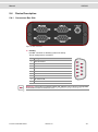
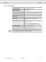
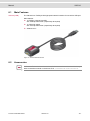
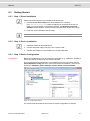
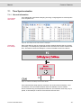
Manual FlexRay Interface Family VN7570 / VN7572 / VN7600 / VN7610 Version 5.0 English Imprint Vector Informatik GmbH Ingersheimer Straße 24 D-70499 Stuttgart The information and data given in this user manual can be changed without prior notice. No part of this manual may be reproduced in any form or by any means without the written permission of the publisher, regardless of which method or which instruments, electronic or mechanical, are used. All technical information, drafts, etc. are liable to law of copyright protection. Copyright 2015, Vector Informatik GmbH. All rights reserved. Manual Contents Contents 1 Introduction 5 1.1 Safety Instructions and Hazard Warnings 1.1.1 Proper Use and Intended Purpose 1.1.2 Hazards 1.1.3 Disclaimer 6 6 6 6 1.2 About this User Manual 1.2.1 Certification 1.2.2 Warranty 1.2.3 Registered Trademarks 7 8 8 8 2 FlexRay Interface Family 9 2.1 General Information 10 2.2 Features 11 3 VN7570 12 3.1 Main Features 13 3.2 Accessories 13 3.3 Getting Started 3.3.1 Step 1: Driver Installation 3.3.2 Step 2: Device Preparation 3.3.3 Step 3: Device Installation 3.3.4 Step 4: Device Configuration 3.3.5 Step 5: Quick Test 14 14 14 15 17 17 3.4 Device Description 3.4.1 Connectors 3.4.2 Bus Configuration 3.4.3 Technical Data 18 18 21 23 4 VN7572 24 4.1 Main Features 25 4.2 Accessories 25 4.3 Getting Started 4.3.1 Step 1: Driver Installation 4.3.2 Step 2: Device Preparation 4.3.3 Step 3: Device Installation 4.3.4 Step 4: Device Configuration 4.3.5 Step 5: Quick Test 26 26 26 27 28 28 4.4 Device Description 4.4.1 Connectors 4.4.2 Bus Configuration 4.4.3 Technical Data 29 29 32 34 5 VN7600 35 5.1 Main Features 36 5.2 Accessories 36 5.3 Getting Started 5.3.1 Step 1: Driver Installation 37 37 © Vector Informatik GmbH Version 5.0 -3- Manual Contents 5.3.2 5.3.3 5.3.4 5.3.5 Step 2: Device Preparation Step 3: Device Installation Step 4: Device Configuration Step 5: Quick Test 37 38 38 39 5.4 Device Description 5.4.1 Connectors Bus Side 5.4.2 Connectors USB Side 5.4.3 LEDs 5.4.4 Technical Data 40 40 42 43 44 6 VN7610 45 6.1 Main Features 46 6.2 Accessories 46 6.3 Getting Started 6.3.1 Step 1: Driver Installation 6.3.2 Step 2: Device Installation 6.3.3 Step 3: Device Configuration 6.3.4 Step 4: Quick Test 47 47 47 47 48 6.4 Device Description 6.4.1 Connectors 6.4.2 Pin Assignment CH1 and CH2 6.4.3 LEDs 6.4.4 Technical Data 49 49 49 50 50 7 Common Features 51 7.1 Time Synchronization 7.1.1 General Information 7.1.2 Software Sync 7.1.3 Hardware Sync 52 52 54 55 7.2 Trigger 57 8 Driver Installation 58 8.1 Minimum Requirements 59 8.2 Hints 60 8.3 Vector Driver Setup 61 8.4 Vector Hardware Configuration 63 8.5 Loop Tests 8.5.1 CAN 8.5.2 FlexRay 8.5.3 MOST 8.5.4 Ethernet 65 65 68 69 70 © Vector Informatik GmbH Version 5.0 -4- Manual Introduction 1 Introduction In this chapter you find the following information: 1.1 Safety Instructions and Hazard Warnings Proper Use and Intended Purpose Hazards Disclaimer page 6 1.2 About this User Manual Certification Warranty Registered Trademarks page 7 © Vector Informatik GmbH Version 5.0 -5- Manual 1.1 Introduction Safety Instructions and Hazard Warnings Caution: In order to avoid personal injuries and damage to property, you have to read and understand the following safety instructions and hazard warnings prior to installation and use of this interface. Keep this documentation (manual) always near the interface. 1.1.1 Proper Use and Intended Purpose Caution: The interface is designed for analyzing, controlling and otherwise influencing control systems and electronic control units. This includes, inter alia, bus systems like CAN, LIN, K-Line, MOST, FlexRay, Ethernet and/or BroadR-Reach. The interface may only be operated in a closed state. In particular, printed circuits must not be visible. The interface may only be operated (i) according to the instructions and descriptions of this manual; (ii) with the electric power supply designed for the interface, e.g. USB-powered power supply; and (iii) with accessories manufactured or approved by Vector. The interface is exclusively designed for use by skilled personnel as its operation may result in serious personal injuries and damage to property. Therefore, only those persons may operate the interface who (i) have understood the possible effects of the actions which may be caused by the interface; (ii) are specifically trained in the handling with the interface, bus systems and the system intended to be influenced; and (iii) have sufficient experience in using the interface safely. The knowledge necessary for the operation of the interface can be acquired in workshops and internal or external seminars offered by Vector. Additional and interface specific information, such as „Known Issues“, are available in the „Vector KnowledgeBase“ on Vector´s website at www.vector.com. Please consult the „Vector KnowledgeBase“ for updated information prior to the operation of the interface. 1.1.2 Hazards Caution: The interface may control and/or otherwise influence the behavior of control systems and electronic control units. Serious hazards for life, body and property may arise, in particular, without limitation, by interventions in safety relevant systems (e.g. by deactivating or otherwise manipulating the engine management, steering, airbag and/or braking system) and/or if the interface is operated in public areas (e.g. public traffic, airspace). Therefore, you must always ensure that the interface is used in a safe manner. This includes, inter alia, the ability to put the system in which the interface is used into a safe state at any time (e.g. by „emergency shutdown“), in particular, without limitation, in the event of errors or hazards. Comply with all safety standards and public regulations which are relevant for the operation of the system. Before you operate the system in public areas, it should be tested on a site which is not accessible to the public and specifically prepared for performing test drives in order to reduce hazards. 1.1.3 Disclaimer Caution: Claims based on defects and liability claims against Vector are excluded to the extent damages or errors are caused by improper use of the interface or use not according to its intended purpose. The same applies to damages or errors arising from insufficient training or lack of experience of personnel using the interface. © Vector Informatik GmbH Version 5.0 -6- Manual 1.2 Introduction About this User Manual Conventions In the two following charts you will find the conventions used in the user manual regarding utilized spellings and symbols. Style Utilization bold Blocks, surface elements, window- and dialog names of the software. Accentuation of warnings and advices. [OK] Push buttons in brackets File|Save Notation for menus and menu entries Microsoft Legally protected proper names and side notes. Source Code File name and source code. Hyperlink Hyperlinks and references. <CTRL>+<S> Notation for shortcuts. Symbol Utilization Here you can obtain supplemental information. This symbol calls your attention to warnings. Here you can find additional information. Here is an example that has been prepared for you. Step-by-step instructions provide assistance at these points. Instructions on editing files are found at these points. This symbol warns you not to edit the specified file. © Vector Informatik GmbH Version 5.0 -7- Manual Introduction 1.2.1 Certification Certified Quality Vector Informatik GmbH has ISO 9001:2008 certification. The ISO standard is a globManagement System ally recognized standard. 1.2.2 Warranty Restriction of warranty We reserve the right to change the contents of the documentation and the software without notice. Vector Informatik GmbH assumes no liability for correct contents or damages which are resulted from the usage of the documentation. We are grateful for references to mistakes or for suggestions for improvement to be able to offer you even more efficient products in the future. 1.2.3 Registered Trademarks Registered trademarks All trademarks mentioned in this documentation and if necessary third party registered are absolutely subject to the conditions of each valid label right and the rights of particular registered proprietor. All trademarks, trade names or company names are or can be trademarks or registered trademarks of their particular proprietors. All rights which are not expressly allowed are reserved. If an explicit label of trademarks, which are used in this documentation, fails, should not mean that a name is free of third party rights. Windows, Windows 7, Windows 8.1 are trademarks of the Microsoft Corporation. © Vector Informatik GmbH Version 5.0 -8- Manual FlexRay Interface Family 2 FlexRay Interface Family In this chapter you find the following information: 2.1 General Information page 10 2.2 Features page 11 © Vector Informatik GmbH Version 5.0 -9- Manual 2.1 FlexRay Interface Family General Information FlexRay Interfaces The FlexRay interface family offers a future-proofed and powerful solution for development, simulation, test, measurement or calibration of FlexRay networks through an FPGA-based FlexRay communication controller. The devices are able to transmit and receive data as well as null frames. The detection of invalid frames on the bus is also possible. Future features can be added in the field by Software and FPGA updates. Figure 1: Devices of the FlexRay interface family The FPGA-based Startup Monitoring is particularly helpful at the beginning of a FlexRay development. It allows you to detect FlexRay frames and symbols, even before the communication controller has synchronized itself to the bus. This also facilitates the analysis of problems in the bus configuration. Another advantage of the independent Startup Monitoring unit is that it can be operated at the same time as the communication controller. This allows you to do both Startup Monitoring and normal transmit operation without restart. You can easily test non-coldstart nodes with only one interface. For this purpose the FlexRay interface family offers you a second communication controller. Bus configuration The FlexRay interfaces use bus transceivers on replaceable plug-in boards (Piggybacks). Hence, the FlexRay interfaces are well prepared for future use. © Vector Informatik GmbH Version 5.0 - 10 - Manual 2.2 FlexRay Interface Family Features Further properties The highlights at a glance: Detailed analysis of the FlexRay communication through the FPGA-based communication controller Simulation of comprehensive networks due to the 2 MB transmission memory (parallel configuration of more than 1000 send messages) Coldstart of the FlexRay cluster without needing to add a network node FlexRay channel A and B Analysis of the network startup via an independent monitoring unit Dynamic reconfiguration of the CC buffers Transmission and reception of data and null frames Detection of invalid frames Cycle multiplexing Support of the maximum payload of 254 bytes In-cycle response Hardware-based incrementing of a payload area Support of PDUs Time synchronization Trigger input and output (not supported in all devices) Low PC loading due to DMA (Direct Memory Access) © Vector Informatik GmbH Version 5.0 - 11 - Manual VN7570 3 VN7570 In this chapter you find the following information: 3.1 Main Features page 13 3.2 Accessories page 13 3.3 Getting Started Step 1: Driver Installation Step 2: Device Preparation Step 3: Device Installation Step 4: Device Configuration Step 5: Quick Test page 14 3.4 Device Description Connectors Bus Configuration Technical Data page 18 © Vector Informatik GmbH Version 5.0 - 12 - Manual 3.1 VN7570 Main Features VN7570 (PCIe) The VN7570 is a FlexRay/CAN/LIN/IO network interface for use with a PCIe slot. Main features: 1x D-SUB62 connector for FlexRay, CAN/LIN and IO 1x Binder connector for hardware time synchronization 1x internal connector for hardware time synchronization 1x plug-in location for CAN/LINpiggies or FR compact Piggybacks (CH1) 3x plug-in locations for CAN/LINpiggies (CH2…CH4) 4x on-board CAN high-speed 1051cap transceivers (capacitively decoupled, CH5…CH8) 1x plug-in location for IOpiggy (digital/analog input/output) Figure 2: VN7570 3.2 Accessories Reference: Further information on the available accessories can be found in the separate accessories manual on the driver CD in \Documentation\Accessories. © Vector Informatik GmbH Version 5.0 - 13 - Manual 3.3 VN7570 Getting Started 3.3.1 Step 1: Driver Installation Please use the drivers from the included Vector Driver Disk. 1. Execute Vector Driver Setup from the autostart menu or directly from \Drivers\Setup.exe before the VN7570 is inserted into an empty PCIe slot. If you have already inserted the VN7570, the Windows found new Hardware wizard appears. Close this wizard and then execute the driver setup. 2. Finish the driver installation with the setup. Note: Further information on the driver installation can be found on page 58. 3.3.2 Step 2: Device Preparation Bus types In order to connect the device to the FlexRay/CAN/LIN/K-Line bus, one or more Piggybacks with suitable transceivers have to be inserted before. For CAN there are also on-board transceivers available. A list of compatible Piggybacks can be found in the accessories manual on the driver CD in \Documentation\Accessories. Note: LINpiggies have to be inserted after CANpiggies (in descending order). If you intend to use only one LINpiggy, please use the last plug-in location (CH4). J1708 should be handled like CAN. Please refer to section Bus Configuration on page 21 for further details. If an FRpiggyC is inserted (CH1), only two additional LINpiggies can be used (CH3/CH4). A third LINpiggy at CH2 returns a configuration error in Vector Hardware Config. © Vector Informatik GmbH Version 5.0 - 14 - Manual VN7570 Please follow these instructions if no Piggyback is inserted or if another Piggyback needs to be inserted. Do not touch the bottom and the topside of the PCBs (VN7570 main board and Piggybacks) to prevent electrical damage. 1. Detach the screw with the screw protection and remove the Piggyback carefully. CH1 CH2 FR CAN LIN CAN LIN CH4 CH3 CAN LIN CAN LIN CH9 IO 2. Insert the replacement Piggyback. The connectors must fit and must not be displaced laterally. 3. The Piggyback has to be fixed again with the screw and the screw protection. 3.3.3 Step 3: Device Installation Caution: Turn off the main power supply and disconnect your computer’s power cord. Otherwise systems using an ATX power supply unit with soft power off may still be powering the PCIe slot. This can damage your PCIe card when it is inserted into the slot. Caution: Do not force the VN7570 into the slot. Make sure that the connectors of the card’s PCIe connector are aligned with the bus connector on the motherboard before you insert the card into the slot. If it does not fit properly, gently remove it and try again. Info: Please observe all safety precautions prescribed by your PC manufacturer for card installation! Info: Do not touch the bottom and the topside of the PCBs (VN7570 main board and Piggybacks) to prevent electrical damage during assembly. 1. Install the drivers as described before. 2. Turn off the computer and all peripheral devices. 3. Unplug the power cord from the wall outlet. 4. Touch a metal plate on your computer to ground yourself to discharge any static electricity. © Vector Informatik GmbH Version 5.0 - 15 - Manual VN7570 5. Remove the computer cover and the metal brackets from an unused slot. 6. Align the VN7570 with the PCIe slot and press it gently but firmly into the slot. 7. Replace the computer cover. 8. Plug in the power cord. 9. Turn on the computer. © Vector Informatik GmbH Version 5.0 - 16 - Manual VN7570 3.3.4 Step 4: Device Configuration Configuration Before the installed device can be used in an application (e. g. CANalyzer, CANoe), it has to be properly configured for the needed use case. This configuration and management of all installed Vector devices is done with the Vector Hardware Config tool which comes with the driver installation. The tool can be found in: Windows | Start | Settings | Control Panel | Vector Hardware. Figure 3: Configuring the device For the quick test described in this manual no further configuration is required. Note: Further details on the Vector Hardware Config tool can be found on page 63. 3.3.5 Step 5: Quick Test Note: Please refer to the loop test for FlexRay and CAN described in the installation instructions (see page 58). © Vector Informatik GmbH Version 5.0 - 17 - Manual 3.4 VN7570 Device Description 3.4.1 Connectors D-SUB62 Internal Hardware Sync Sync Figure 4: VN7570 connectors D-SUB62 The D-SUB62 connector provides all input and output pins of the inserted Piggybacks including the on-board CAN transceivers. The pins of the D-SUB62 connector are grouped as follows: Figure 5: D-SUB62 connector pin assignments The pin assignments of CH1…CH4 depend on the inserted Piggybacks. CH5…CH8 are assigned to the on-board CAN transceivers. The remaining pins are reserved for IO purposes and are assigned to the IOpiggy. © Vector Informatik GmbH Version 5.0 - 18 - Manual VN7570 Piggyback D-SUB62/9 Matrix On-board CAN CH 1 CH 2 CH 3 CH 4 D-SUB9 CH 5 CH 6 CH 7 CH D-SUB9 8 45 47 50 53 (1)* - - - - 22 3 28 9 (2)* 12 13 14 15 (2) CAN Low 1 25 7 31 (3)* 54 55 56 57 (3) GND 23 4 29 10 (4)* - - - - (4) N. c. 6 6 6 6 (5)* 6 6 6 6 (5) Shield 2 26 8 32 (6)* - - - - (6) N. c. 24 5 30 11 (7)* 33 34 35 36 43 27 48 51 (8)* - - - - (8) N. c. 44 46 49 52 (9)* - - - - (9) N. c. (1) N. c. (7) CAN High * Depends on the inserted Piggyback. Further information can be found in the separate accessories manual on the driver CD. N. c.: Not connected Trigger pin Trigger output If an FRpiggy 1082cap is inserted (CH1), pin 45 of the D-SUB62 connector can be used as trigger output (low active, 5V/GND, max. input current 200 mA). The configuration of the trigger is set in the application (e. g. CANoe). Reference: Information on suitable cables and adapters can be found in the separate accessories manual on the driver CD in \Documentation\Accessories. IO pins (IOpiggy) If an IOpiggy is inserted the pin assignment at the D-SUB62 connector is as follows: Pin 16 17 18 19 Pinout 1 Pinout 2 Digital In 1 Digital In 3 Digital In 5 Digital In 7 Digital Out 1 Digital Out 3 38 39 Digital Out 1 - Digital Out 3 2 - 3 - - 3 - - Digital Out 5b Digital GND Digital In 0 Digital Out 01 Digital Out 02 Digital In 2 1 2 Digital In 4 Digital Out 2 Digital Out 2 PWM 1 - 3 - - 3 Digital Out 4a 40 Digital In 6 Digital Out 5a - - 41 PWM 0 Capture - - 58 59 60 © Vector Informatik GmbH 1 Pinout 4 2 Digital Out 4b 20 37 Pinout 3 1 Analog GND Analog In 0 Analog Out 01 - - Analog In 1 1 - - Analog Out 1 Version 5.0 - 19 - Manual VN7570 1 2 3 Pin Pinout 1 Pinout 2 Pinout 3 Pinout 4 61 Analog In 2 - - - 62 Analog In 3 - - - Push-Pull Open-Drain a/b line: Relay switched, external signal at a is switched to b Note: Further details on the internal wiring at each IO pin can be found in the separate accessories manual on the driver CD (see section IOpiggy). Sync This connector (Binder type 711) can be used for time synchronization of different Vector devices (see page 52). Pin Assignment 1 Not connected 2 Synchronization line (low active) 3 GND Internal hardware sync connector Multiple VN7570 can also be synchronized via the internal 10-pin connector (angled) above the IOpiggy slot. For synchronization a ribbon cable with a 10-pin standard connector is required. Pin Assignment 1 GND 2..8 Reserved. Do not connect. 9 Synchronization line (low active) 10 Internal sync supply (output 5 V, 35 mA) Info: The simultaneous use of the external and internal time synchronization between two devices is not possible. © Vector Informatik GmbH Version 5.0 - 20 - Manual VN7570 3.4.2 Bus Configuration Piggybacks for CH1…CH4 The VN7570 offers four Piggyback plug-in locations (CH1…CH4). Depending on requirements, electrically decoupled FlexRay (only CH1), CAN High-Speed, CAN LowSpeed, CAN Single Wire, J1708 or LIN transceivers may be used. In addition, four electrically decoupled built-in CAN TJA1051 (high-speed) transceivers are available (CH5…CH8). The remaining pins are reserved for dedicated IO tasks. CH1 CH2 CH9 FR CAN LIN CAN LIN IO CH4 CH3 CAN LIN CAN LIN Figure 6: Piggyback plug-in locations Note: LINpiggies have to be inserted after CANpiggies (in descending order). If you intend to use only one LINpiggy, please use the last plug-in location (CH4). J1708 should be handled like CAN. Plug-in location Piggyback CH1 CH2 CH3 CH4 CH5 CH6 CH7 CH8 CH9 1 2 3 4 (fix) (fix) (fix) (fix) 5 CAN or or or LIN CAN 1051 CAN 1051 CAN 1051 CAN 1051 IO or or FR Caution: If an FRpiggy is inserted (CH1), only two additional LINpiggies can be used (CH3/CH4). A third LINpiggy at CH2 returns a configuration error in Vector Hardware Config. © Vector Informatik GmbH Version 5.0 - 21 - Manual Examples VN7570 The following tables show examples of possible combinations: 4x CAN CH1 CH2 CH3 CH4 CH5 CH6 CH7 CH8 CH9 Plug-in location 1 2 3 4 (fix) (fix) (fix) (fix) 5 Piggyback - - - - CAN CAN CAN CAN - Channel configuration - - - - CAN CAN CAN CAN - CH1 CH2 CH3 CH4 CH5 CH6 CH7 CH8 CH9 1 2 3 4 (fix) (fix) (fix) (fix) 5 Piggyback CAN CAN CAN CAN CAN CAN CAN CAN IO Channel configuration CAN CAN CAN CAN CAN CAN CAN CAN IO CH1 CH2 CH3 CH4 CH5 CH6 CH7 CH8 CH9 Plug-in location 1 2 3 4 (fix) (fix) (fix) (fix) 5 Piggyback FR - - - CAN CAN CAN CAN - Channel configuration FR - - - CAN CAN CAN CAN - CH1 CH2 CH3 CH4 CH5 CH6 CH7 CH8 CH9 1 2 3 4 (fix) (fix) (fix) (fix) 5 Piggyback CAN - LIN LIN CAN CAN CAN CAN - Channel configuration CAN - LIN LIN CAN CAN CAN CAN - CH1 CH2 CH3 CH4 CH5 CH6 CH7 CH8 CH9 1 2 3 4 (fix) (fix) (fix) (fix) 5 Piggyback FR CAN LIN LIN CAN CAN CAN CAN IO Channel configuration FR CAN LIN LIN CAN CAN CAN CAN IO 8x CAN 1x IO Plug-in location 1x FlexRay 4x CAN 5x CAN 2x LIN Plug-in location 1x FR 5x CAN 2x LIN 1x IO Plug-in location © Vector Informatik GmbH Version 5.0 - 22 - Manual VN7570 3.4.3 Technical Data FlexRay communicationcontroller (analysis) Bosch E-Ray (FPGA) FlexRay communicationcontroller (startup) Fujitsu MB88121 Memory for data transmission 2 MB FlexRay channels 1x channel A and B Maximum FlexRay payload 254 bytes CAN/CAN-FD channels Max. 8 (four configurable via Piggybacks) CAN: up to 2 Mbit/s CAN-FD: up to 8 Mbit/s LIN channels Max. 4 (configurable via Piggybacks), up to 330 kbit/s Transceiver See plug-in board (FRpiggyC, CAN/LINpiggies) PC interface PCIe 1x Power supply Internal via PCIe, 3.3 V Typ. 6 W (1x FRpiggy, 3x CANpiggy, 1x IOpiggy) Temperature range (ambient temperature of the device) Operation: -40 °C...+65 °C Storage: -40 °C...+85 °C Dimensions (LxWxH) 127 mm x 178 mm x 18 mm Operating system Windows 7 (SP1), 32 bit or 64 bit Windows 8.1, 32 bit or 64 bit © Vector Informatik GmbH Version 5.0 - 23 - Manual VN7572 4 VN7572 In this chapter you find the following information: 4.1 Main Features page 25 4.2 Accessories page 25 4.3 Getting Started Step 1: Driver Installation Step 2: Device Preparation Step 3: Device Installation Step 4: Device Configuration Step 5: Quick Test page 26 4.4 Device Description Connectors Bus Configuration Technical Data page 29 © Vector Informatik GmbH Version 5.0 - 24 - Manual 4.1 VN7572 Main Features VN7572 (PCIe) The VN7572 is a FlexRay/CAN/LIN/IO network interface for use with a PCIe slot. Main features: 1x D-SUB62 connector for FlexRay, CAN/LIN and IO 1x Binder connector for hardware time synchronization 1x internal connector for hardware time synchronization 2x plug-in locations for FR compact Piggybacks or CAN/LINpiggies (CH1/CH2) 2x plug-in locations for CAN/LINpiggies (CH3/CH4) 4x on-board CAN high-speed 1051cap transceivers (capacitively decoupled, CH5…CH8) 1x plug-in location for IOpiggy (digital/analog input/output) Figure 7: VN7572 4.2 Accessories Reference: Further information on the available accessories can be found in the separate accessories manual on the driver CD in \Documentation\Accessories. © Vector Informatik GmbH Version 5.0 - 25 - Manual 4.3 VN7572 Getting Started 4.3.1 Step 1: Driver Installation Please use the drivers from the included Vector Driver Disk. 1. Execute Vector Driver Setup from the autostart menu or directly from \Drivers\Setup.exe before the VN7572 is inserted into an empty PCIe slot. If you have already inserted the VN7572, the Windows found new Hardware wizard appears. Close this wizard and then execute the driver setup. 2. Finish the driver installation with the setup. Note: Further information on the driver installation can be found on page 58. 4.3.2 Step 2: Device Preparation Bus types In order to connect the device to the FlexRay/CAN/LIN bus, one or more Piggybacks with suitable transceivers have to be inserted before (see section Bus Configuration on page 32). For CAN there are also on-board transceivers available. A list of compatible Piggybacks can be found in the accessories manual on the driver CD in \Documentation\Accessories. Note: Inserting order for FRpiggies: CH1…CH2. Inserting order for LINpiggies: CH4…CH1. Inserting order for CAN/J1708piggies: CH1…CH4, but after FRpiggies and before LINpiggies. © Vector Informatik GmbH Version 5.0 - 26 - Manual VN7572 Please follow these instructions if no Piggyback is inserted or if another Piggyback needs to be inserted. Do not touch the bottom and the topside of the PCBs (VN7572 main board and Piggybacks) to prevent electrical damage. 1. Detach the screw with the screw protection and remove the Piggyback carefully. CH1 CH2 CH9 FR CAN LIN FR CAN LIN IO CH4 CH3 CAN LIN CAN LIN 2. Insert the replacement Piggyback. The connectors must fit and must not be displaced laterally. 3. The Piggyback has to be fixed again with the screw and the screw protection. 4.3.3 Step 3: Device Installation Caution: Turn off the main power supply and disconnect your computer’s power cord. Otherwise systems using an ATX power supply unit with soft power off may still be powering the PCIe slot. This can damage your PCIe card when it is inserted into the slot. Caution: Do not force the VN7572 into the slot. Make sure that the connectors of the card’s PCIe connector are aligned with the bus connector on the motherboard before you insert the card into the slot. If it does not fit properly, gently remove it and try again. Info: Please observe all safety precautions prescribed by your PC manufacturer for card installation! Info: Do not touch the bottom and the topside of the PCBs (VN7572 main board and Piggybacks) to prevent electrical damage during assembly. 1. Install the drivers as described before. 2. Turn off the computer and all peripheral devices. 3. Unplug the power cord from the wall outlet. © Vector Informatik GmbH Version 5.0 - 27 - Manual VN7572 4. Touch a metal plate on your computer to ground yourself to discharge any static electricity. 5. Remove the computer cover and the metal brackets from an unused slot. 6. Align the VN7572 with the PCIe slot and press it gently but firmly into the slot. 7. Replace the computer cover. 8. Plug in the power cord. 9. Turn on the computer. 4.3.4 Step 4: Device Configuration Configuration Before the installed device can be used in an application (e. g. CANalyzer, CANoe), it has to be properly configured for the needed use case. This configuration and management of all installed Vector devices is done with the Vector Hardware Config tool which comes with the driver installation. The tool can be found in: Windows | Start | Settings | Control Panel | Vector Hardware. Figure 8: Configuring the device For the quick test described in this manual no further configuration is required. Note: Further details on the Vector Hardware Config tool can be found on page 63. 4.3.5 Step 5: Quick Test Note: Please refer to the loop test for FlexRay and CAN described in the installation instructions (see page 58). © Vector Informatik GmbH Version 5.0 - 28 - Manual 4.4 VN7572 Device Description 4.4.1 Connectors D-SUB62 Internal Hardware Sync Sync Figure 9: VN7572 connectors D-SUB62 The D-SUB62 connector provides all input and output pins of the inserted Piggybacks including the on-board CAN transceivers. The pins of the D-SUB62 connector are grouped as follows: Figure 10: D-SUB62 connector pin assignments The pin assignments of CH1…CH4 depend on the inserted Piggybacks. CH5…CH8 are assigned to the on-board CAN transceivers. The remaining pins are reserved for IO purposes and are assigned to the IOpiggy. © Vector Informatik GmbH Version 5.0 - 29 - Manual VN7572 Piggyback D-SUB62/9 Matrix On-board CAN CH 1 CH 2 CH 3 CH 4 D-SUB9 CH 5 CH 6 CH 7 CH D-SUB9 8 45 47 50 53 (1)* - - - - 22 3 28 9 (2)* 12 13 14 15 (2) CAN Low 1 25 7 31 (3)* 54 55 56 57 (3) GND 23 4 29 10 (4)* - - - - (4) N. c. 6 6 6 6 (5)* 6 6 6 6 (5) Shield 2 26 8 32 (6)* - - - - (6) N. c. 24 5 30 11 (7)* 33 34 35 36 43 27 48 51 (8)* - - - - (8) N. c. 44 46 49 52 (9)* - - - - (9) N. c. (1) N. c. (7) CAN High * Depends on the inserted Piggyback. Further information can be found in the separate accessories manual on the driver CD. N. c.: Not connected Trigger pins The D-SUB62 connector offers up to two trigger outputs (low active, 5V/GND, max. input current 200 mA) if an FRpiggyC 1082cap is inserted (see section Bus Configuration on page 32): Trigger output at CH1: pin 45. Trigger output at CH2: pin 47. Further information on triggers can be found in section Trigger on page 57. Reference: Information on suitable cables and adapters can be found in the separate accessories manual on the driver CD in \Documentation\Accessories. IO pins (IOpiggy) If an IOpiggy is inserted the pin assignment at the D-SUB62 connector is as follows: Pin 16 17 18 19 Pinout 1 Pinout 2 Digital In 1 Digital In 3 Digital In 5 Digital In 7 Digital Out 1 1 Digital Out 3 38 39 © Vector Informatik GmbH Pinout 4 Digital Out 1 2 - Digital Out 3 2 - 3 - - 3 - - Digital Out 4b Digital Out 5b 20 37 Pinout 3 1 Digital GND Digital In 0 Digital Out 01 Digital Out 02 Digital In 2 1 2 Digital In 4 Digital Out 2 Digital Out 2 PWM 1 - 3 - - 3 Digital Out 4a 40 Digital In 6 Digital Out 5a - - 41 PWM 0 Capture - - Version 5.0 - 30 - Manual VN7572 Pin Pinout 1 Pinout 2 58 2 3 Pinout 4 Analog GND Analog In 0 Analog Out 01 - - 60 Analog In 1 1 Analog Out 1 - - 61 Analog In 2 - - - 62 Analog In 3 - - - 59 1 Pinout 3 Push-Pull Open-Drain a/b line: Relay switched, external signal at a is switched to b Note: Further details on the internal wiring at each IO pin can be found in the separate accessories manual on the driver CD (see section IOpiggy). Sync This connector (Binder type 711) can be used for time synchronization of different Vector devices (see page 52). Pin Assignment 1 Not connected 2 Synchronization line (low active) 3 GND Internal hardware sync connector Multiple VN7572 can also be synchronized via the internal 10-pin connector (angled) above the IOpiggy slot. For synchronization a ribbon cable with a 10-pin standard connector is required. Pin Assignment 1 GND 2..8 Reserved. Do not connect. 9 Synchronization line (low active) 10 Internal sync supply (output 5 V, 35 mA) Info: The simultaneous use of the external and internal time synchronization between two devices is not possible. © Vector Informatik GmbH Version 5.0 - 31 - Manual VN7572 4.4.2 Bus Configuration Piggybacks for CH1…CH4 The VN7572 offers four Piggyback plug-in locations (CH1…CH4). Depending on requirements, electrically decoupled FlexRay, CAN High-Speed, CAN Low-Speed, CAN Single Wire, J1708 or LIN transceivers may be used. In addition, four electrically decoupled built-in CAN TJA1051 (high-speed) transceivers are available (CH5…CH8). The remaining pins are reserved for dedicated IO tasks (CH9). CH1 CH2 FR CAN LIN FR CAN LIN CH4 CH3 CAN LIN CAN LIN CH9 IO Figure 11: Piggyback plug-in locations Note: Inserting order for FRpiggies: CH1…CH2. Inserting order for LINpiggies: CH4…CH1. Inserting order for CAN/J1708piggies: CH1…CH4, but after FRpiggies and before LINpiggies. Plug-in location Piggyback © Vector Informatik GmbH CH1 CH2 CH3 CH4 CH5 CH6 CH7 CH8 CH9 1 2 3 4 (fix) (fix) (fix) (fix) 5 CAN or or or LIN CAN 1051 CAN 1051 CAN 1051 CAN 1051 IO or or FR or FR Version 5.0 - 32 - Manual Examples VN7572 The following tables show examples of possible combinations: 4x CAN CH1 CH2 CH3 CH4 CH5 CH6 CH7 CH8 CH9 Plug-in location 1 2 3 4 (fix) (fix) (fix) (fix) 5 Piggyback - - - - CAN CAN CAN CAN - Channel configuration - - - - CAN CAN CAN CAN - CH1 CH2 CH3 CH4 CH5 CH6 CH7 CH8 CH9 1 2 3 4 (fix) (fix) (fix) (fix) 5 Piggyback CAN CAN CAN CAN CAN CAN CAN CAN IO Channel configuration CAN CAN CAN CAN CAN CAN CAN CAN IO CH1 CH2 CH3 CH4 CH5 CH6 CH7 CH8 CH9 Plug-in location 1 2 3 4 (fix) (fix) (fix) (fix) 5 Piggyback FR FR - - CAN CAN CAN CAN - Channel configuration FR FR - - CAN CAN CAN CAN - CH1 CH2 CH3 CH4 CH5 CH6 CH7 CH8 CH9 1 2 3 4 (fix) (fix) (fix) (fix) 5 Piggyback CAN - LIN LIN CAN CAN CAN CAN - Channel configuration CAN - LIN LIN CAN CAN CAN CAN - CH1 CH2 CH3 CH4 CH5 CH6 CH7 CH8 CH9 1 2 3 4 (fix) (fix) (fix) (fix) 5 Piggyback FR FR CAN LIN CAN CAN CAN CAN IO Channel configuration FR FR CAN LIN CAN CAN CAN CAN IO 8x CAN 1x IO Plug-in location 2x FlexRay 4x CAN 5x CAN 2x LIN Plug-in location 2x FR 5x CAN 1x LIN 1x IO Plug-in location © Vector Informatik GmbH Version 5.0 - 33 - Manual VN7572 4.4.3 Technical Data FlexRay communicationcontroller (analysis) Bosch E-Ray (FPGA) FlexRay communicationcontroller (startup) Bosch E-Ray (FPGA) Memory for data transmission 2 MB FlexRay channels 2x channel A and B Maximum FlexRay payload 254 bytes CAN/CAN-FD channels Max. 8 (four configurable via Piggybacks) CAN: up to 2 Mbit/s CAN-FD: up to 8 Mbit/s LIN channels Max. 4 (configurable via Piggybacks), up to 330 kbit/s Transceiver See plug-in board (FRpiggyC, CAN/LINpiggies) PC interface PCIe 1x Power supply Internal via PCIe, 3.3 V Typ. 7 W (1x FRpiggy, 3x CANpiggy, 1x IOpiggy) Temperature range (ambient temperature of the device) Operation: -40 °C...+50 °C Storage: -40 °C...+85 °C Dimensions (LxWxH) 127 mm x 178 mm x 18 mm Operating system Windows 7 (SP1), 32 bit or 64 bit Windows 8.1, 32 bit or 64 bit © Vector Informatik GmbH Version 5.0 - 34 - Manual VN7600 5 VN7600 In this chapter you find the following information: 5.1 Main Features page 36 5.2 Accessories page 36 5.3 Getting Started Step 1: Driver Installation Step 2: Device Preparation Step 3: Device Installation Step 4: Device Configuration Step 5: Quick Test page 37 5.4 Device Description Connectors Bus Side Connectors USB Side LEDs Technical Data page 40 © Vector Informatik GmbH Version 5.0 - 35 - Manual 5.1 VN7600 Main Features VN7600 (USB) The VN7600 is a FlexRay/CAN network interface for use with a USB port. Main features: 1x D-SUB9 connector for FlexRay (channel A and B) 3x D-SUB9 connector for CAN 2x Binder connector for power supply and hardware synchronization 1x Binder connector for trigger Figure 12: VN7600 5.2 Accessories Reference: Further information on the available accessories can be found in the separate accessories manual on the driver CD in \Documentation\Accessories. © Vector Informatik GmbH Version 5.0 - 36 - Manual 5.3 VN7600 Getting Started 5.3.1 Step 1: Driver Installation Please use the drivers from the included Vector Driver Disk. 1. Execute Vector Driver Setup from the autostart menu or directly from \Drivers\Setup.exe before the VN7600 is connected to the PC via USB. If you have already connected the VN7600, the Windows found new Hardware wizard appears. Close this wizard and then execute the driver setup. 2. Finish the driver installation with the setup. Note: Further information on the driver installation can be found on page 58. 5.3.2 Step 2: Device Preparation Bus types In order to connect the device to the FlexRay or CAN bus, one or more Piggybacks with suitable transceivers have to be inserted before. A list of compatible Piggybacks can be found in the accessories manual on the driver CD in \Documentation\Accessories. Please follow these instructions if no Piggyback is inserted or if another Piggyback needs to be inserted. Do not touch the bottom and the topside of the PCBs (VN7600 main board and Piggybacks) to prevent electrical damage. 1. First, disconnect the VN7600 from the PC and the power supply. 2. Loosen the VN7600 housing screws on the side with the D-SUB9 connector. This requires removing the two black decorative caps. Then carefully pull the PCboard out of the housing. 3. The Piggybacks are fastened by a screw and retainer. Please loosen the appropriate screw including the retainer and carefully remove the Piggyback from the mounting location. CH3 CH2 CH1 CANpiggy CANpiggy CANpiggy FRpiggy 4. Insert the replacement Piggyback. When doing this please make sure that the connectors are not laterally offset. © Vector Informatik GmbH Version 5.0 - 37 - Manual VN7600 5. Secure the new Piggyback with the appropriate screw and retainer. 6. Place the VN7600 main board back in the housing verifying that it is inserted properly. This operation involves placing the housing on a table with its back side (side with the bar code) facing upward. Then the main board with the Piggyback is inserted into the upper guide rails. 7. It should be possible to slide the main board in the housing up to a few millimeters from the end without forcing it in. Close the housing by applying light pressure, and then secure it with the appropriate screw fasteners. The screws should be secure but not excessively tight. 8. Please also attach the two black decorative caps. 5.3.3 Step 3: Device Installation 1. Install the drivers as described before. 2. Connect the power supply and plug it into a power outlet. 3. Connect the VN7600 to a free USB2.0 port via the USB cable. 5.3.4 Step 4: Device Configuration Configuration Before the installed device can be used in an application (e. g. CANalyzer, CANoe), it has to be properly configured for the needed use case. This configuration and management of all installed Vector devices is done with the Vector Hardware Config tool which comes with the driver installation. The tool can be found in: Windows | Start | Settings | Control Panel | Vector Hardware. Figure 13: Configuring the device For the quick test described in this manual no further configuration is required. Note: Further details on the Vector Hardware Config tool can be found on page 63. © Vector Informatik GmbH Version 5.0 - 38 - Manual VN7600 5.3.5 Step 5: Quick Test Note: Please refer to the loop test for FlexRay and CAN described in the installation instructions (see page 58). © Vector Informatik GmbH Version 5.0 - 39 - Manual 5.4 VN7600 Device Description 5.4.1 Connectors Bus Side Figure 14: Main connectors FlexRay D-SUB9 connector for FlexRay (channel A and B). The pin assignment is as follows: Pin Assignment 1 Not connected 2 BM Channel A 3 GND 4 BM Channel B 5 Shield 6 Not connected 7 BP Channel A 8 BP Channel B 9 Not connected Reference: Information on suitable cables and adapters can be found in the separate accessories manual on the driver CD in \Documentation\Accessories. © Vector Informatik GmbH Version 5.0 - 40 - Manual VN7600 CAN1…CAN3 D-SUB9 connectors for CAN. The pin assignments depend on the used Piggyback configuration inside the VN7600. Please refer to the accessories manual on the driver CD. The general CAN pin assignment is as follows: Pin Assignment 1 Not connected 2 CAN Low 3 GND 4 Piggyback dependent 5 Shield 6 Not connected 7 CAN High 8 reserved 9 Piggyback dependent Trigger (Binder type 711) See section Trigger on page 57 for further details. The pin assignment of the connector is as follows: Software Port1 Pin Assignment 1 1 Output voltage 5 V (max. 35 mA) - 2 Trigger In (TTL 5 V, low active) VHmin: 3.0 V / VHmax: 5.5 V VLmin: 0.0 V / VLmax: 0.7 V 3 3 Trigger Out (TTL 5 V, low active) 0 4 Trigger In/Out (5 V, low active) VHmin: 3.0 V / VHmax: 5.5 V VLmin: 0.0 V / VLmax: 0.7 V 1 5 Trigger In/Out (5 V, low active) VHmin: 3.0 V / VHmax: 5.5 V VLmin: 0.0 V / VLmax: 0.7 V 2 6 Reserved. Do not connect. - 7 Reserved. Do not connect. - 8 GND - Used by Vector software, e. g. in CANoe © Vector Informatik GmbH Version 5.0 - 41 - Manual VN7600 5.4.2 Connectors USB Side Figure 15: USB and power/sync connector 2x Power/Sync The VN7600 has two power/sync connectors (Binder type 711) which can be used for time synchronization of different Vector devices (see page 52) or for power. Note: The VN7600 needs to be externally supplied. It does not matter which connector is used to supply the device. Figure 16: Schematic of the power/sync connectors Pin Assignment 1 Power supply 2 Synchronization line (low active) 3 GND USB Connect your PC and the VN7600 via USB to install and to use the device with measurement applications (e. g. CANalyzer, CANoe). © Vector Informatik GmbH Version 5.0 - 42 - Manual VN7600 5.4.3 LEDs FlexRay A, B and Sync The VN7600 has four LEDs with the following meanings: FlexRay A Lights up when data is received or transmitted on channel A. FlexRay B Lights up when data is received or transmitted on channel B. Sync Common LED for both FlexRay channels, which displays the state of the CC. - Off: Offline. - Green: Synchronized. - Orange: Not synchronized. - Red: Error. CAN 1, 2 and 3 Lights up when data is received or transmitted. Power Displays the state of operation: - Green: The device is ready for operation. - Orange: The device is ready for host PC connection. - Orange (blinking): An automatic FPGA update is executed. - Red: Error, the device is not ready for operation. © Vector Informatik GmbH Version 5.0 - 43 - Manual VN7600 5.4.4 Technical Data FlexRay communicationcontroller (analysis) Bosch E-Ray (Altera Cyclone II EP2C70) FlexRay communicationcontroller (startup) Fujitsu MB88121B Memory for data transmission 2 MB FlexRay channels 1x channel A and B Maximum FlexRay payload 254 bytes CAN channels 3 PC interface USB 2.0 Power supply External, 5 V ... 50 V (startup min. 9 V), typical 4.5 W Temperature range Operation*: 0 °C...+55 °C Storage: -40 °C...+85 °C * Based on tests an operating temperature range of -20 °C ... +70 °C is possible, due to components used the guaranteed operational temperature range is 0 °C ... +55 °C. Dimensions (LxWxH) 151 mm x 110 mm x 45 mm Operating system Windows 7 (SP1), 32 bit or 64 bit Windows 8.1, 32 bit or 64 bit Info: The temperature of single housing parts may be higher than the temperature of the environment, even if the device is correctly operated. © Vector Informatik GmbH Version 5.0 - 44 - Manual VN7610 6 VN7610 In this chapter you find the following information: 6.1 Main Features page 46 6.2 Accessories page 46 6.3 Getting Started Step 1: Driver Installation Step 2: Device Installation Step 3: Device Configuration Step 4: Quick Test page 47 6.4 Device Description Connectors Pin Assignment CH1 and CH2 LEDs Technical Data page 49 © Vector Informatik GmbH Version 5.0 - 45 - Manual 6.1 VN7610 Main Features VN7610 (USB) The VN7610 is a FlexRay/CAN high-speed network interface for use with a USB port. Main features: 1x FlexRay (channel A and B) with 1082cap transceiver (capacitively decoupled) 1x CAN high-speed with 1051cap transceiver (capacitively decoupled) Software sync Figure 17: VN7610 FR/CAN Interface 6.2 Accessories Reference: Further information on the available accessories can be found in the separate accessories manual on the driver CD in \Documentation\Accessories. © Vector Informatik GmbH Version 5.0 - 46 - Manual 6.3 VN7610 Getting Started 6.3.1 Step 1: Driver Installation Please use the drivers from the included Vector Driver Disk. 1. Execute Vector Driver Setup from the autostart menu or directly from \Drivers\Setup.exe before the VN7610 is connected to the PC via USB. If you have already connected the VN7610, the Windows found new Hardware wizard appears. Close this wizard and then execute the driver setup. 2. Finish the driver installation with the setup. Note: Further information on the driver installation can be found on page 58. 6.3.2 Step 2: Device Installation 1. Install the drivers as described before. 2. Connect the power supply and plug it into a power outlet. 3. Connect the VN7610 to a free USB2.0 port via the USB cable. 6.3.3 Step 3: Device Configuration Configuration Before the installed device can be used in an application (e. g. CANalyzer, CANoe), it has to be properly configured for the needed use case. This configuration and management of all installed Vector devices is done with the Vector Hardware Config tool which comes with the driver installation. The tool can be found in: Windows | Start | Settings | Control Panel | Vector Hardware. Figure 18: Configuring the device For the quick test described in this manual no further configuration is required. © Vector Informatik GmbH Version 5.0 - 47 - Manual VN7610 Note: Further details on the Vector Hardware Config tool can be found on page 63. 6.3.4 Step 4: Quick Test Note: Please refer to the loop test for FlexRay and CAN described in the installation instructions (see page 58). © Vector Informatik GmbH Version 5.0 - 48 - Manual 6.4 VN7610 Device Description 6.4.1 Connectors D-SUB9 (CH1/2) The VN7610 has a D-SUB9 connector with one FlexRay channel (CH1) and one CAN high-speed channel (CH2). Further information on the pin assignment for CH1/CH2 can be found below. USB Connect your PC and the VN7610 via USB to install and to use the device with measurement applications (e. g. CANoe, CANalyzer). 6.4.2 Pin Assignment CH1 and CH2 D-SUB9 connector The pin assignment of the D-SUB9 connector (CH1 and CH2) is as follows: CH1/CH2 Y cable Use the FR/CANcable 2Y to access both channels on separate D-SUB9 connectors (see accessories manual, part number 05099). Figure 19: FR/CANcable 2Y © Vector Informatik GmbH Version 5.0 - 49 - Manual VN7610 6.4.3 LEDs FlexRay CAN Status Color Description Green FlexRay Communication Controller synchronized. Orange FlexRay Communication Controller not synchronized or errors on bus. Red Error. Color Description Green Data frames have been sent or received correctly. The flashing frequency varies according to the message rate. Orange Error frames have been sent or received. The flashing frequency varies according to the message rate. Red Bus Off. Color Description Green Device is ready for operation/running measurement. Orange Hardware initialization completed. Waiting for device driver. Red Error. Device not working. 6.4.4 Technical Data FlexRay communication-controller (analysis) Bosch E-Ray (FPGA) FlexRay communication-controller (startup) Bosch E-Ray (FPGA) FlexRay channels 1x channel A and B CAN channels 1x CAN high-speed CAN: up to 2 Mbit/s CAN-FD: up to 8 Mbit/s Power supply Internal via USB, typical 2 W Temperature range Operating: -40 °C...+50 °C Shipping and storage: -40 °C...+85 °C Dimensions (LxWxH) 65 mm x 42 mm x 20 mm Weight Approx. 80 g Operating system requirements Windows 7 (SP1), 32 bit or 64 bit Windows 8.1, 32 bit or 64 bit © Vector Informatik GmbH Version 5.0 - 50 - Manual Common Features 7 Common Features In this chapter you find the following information: 7.1 Time Synchronization General Information Software Sync Hardware Sync © Vector Informatik GmbH page 52 Version 5.0 - 51 - Manual 7.1 Common Features Time Synchronization 7.1.1 General Information Time stamps and events Time stamps are useful when analyzing incoming or outgoing data or event sequences on a specific bus. Figure 20: Time stamps of two CAN channels in CANalyzer Generating time stamps Each event which is sent or received by a Vector network interface has an accurate time stamp. Time stamps are generated for each channel in the Vector network interface. The base for these time stamps is a common hardware clock in the device. Figure 21: Common time stamp clock for each channel If the measurement setup requires more than one Vector network interface, a synchronization of all connected interfaces and their hardware clocks is needed. Due to manufacturing and temperature tolerances, the hardware clocks may vary in speed, so time stamps of various Vector devices drift over time. © Vector Informatik GmbH Version 5.0 - 52 - Manual Common Features Figure 22: Example of unsynchronized network interfaces. Independent time stamps drift apart To compensate for these time stamp deviations between the Vector network interfaces, the time stamps can be either synchronized by software or by hardware (see next section). Note: The accuracy of the software sync is typically in range of 100 µs. Note: The accuracy of the hardware sync is typically in range of 1 µs. © Vector Informatik GmbH Version 5.0 - 53 - Manual Common Features 7.1.2 Software Sync Synchronization by software The software time synchronization is driver-based and available for all applications without any restrictions. The time stamp deviations from different Vector network interfaces are calculated and synchronized to the common PC clock. For this purpose no further hardware setup is required. Figure 23: Time stamps of devices are synchronized to the PC clock (accuracy in range of 100 µs) The setting of the software time synchronization can be changed in the Vector Hardware Config tool in General information | Settings | Software time synchronization. Figure 24: Switching on the software synchronization YES The software time synchronization is active. NO The software time synchronization is not active. Use this setting only if the Vector network interfaces are being synchronized over the sync line or if only a single device is used. © Vector Informatik GmbH Version 5.0 - 54 - Manual Common Features 7.1.3 Hardware Sync Synchronization by hardware A more accurate time synchronization of multiple devices is provided by the hardware synchronization which has to be supported by the application (e. g CANalyzer, CANoe). Two Vector network interfaces can therefore be connected with the SYNCcableXL (see accessories manual, part number 05018). In order to synchronize up to five devices at the same time, a distribution box is available (see accessories manual, part number 05085). Figure 25: Example of a time synchronization with multiple devices Figure 26: Example of a time synchronization with VN8912 and additional devices © Vector Informatik GmbH Version 5.0 - 55 - Manual Common Features At each falling edge on the sync line which is initiated by the application, the Vector network interface generates a time stamp that is provided to the application. This allows the application to calculate the deviations between the network interfaces and to synchronize the time stamps to a common time base (master clock) which is defined by the application. Figure 27: Time stamps are synchronized to the master clock (accuracy in range of 1 µs) Note: The hardware synchronization must be supported by the application. For further information please refer to the relevant application manual. Please note that the software synchronization must be disabled (see Vector Hardware Config | General information | Settings | Software time synchronization) if the hardware synchronization is used. © Vector Informatik GmbH Version 5.0 - 56 - Manual 7.2 Trigger Common Features Trigger The FlexRay interface family offers several pins for dedicated trigger applications (see the according pin assignment). The configuration of the triggers and their actions is set in the application (e. g. CANoe). The following picture depicts the internal circuit of a trigger pin. Figure 28: Trigger input and output Input If the trigger pin is used for input, the trigger will be fired by a falling edge on the trigger line. The trigger is processed inside the application. If the trigger input is being wired, the internal 4.7 kOhm resistor must be kept in mind. Figure 29: Trigger input Output If the trigger pin is used for output, the trigger of the application releases a falling edge on the trigger line. By using external pull up resistors, the maximum allowed load is 5 mA. Figure 30: Trigger output © Vector Informatik GmbH Version 5.0 - 57 - Manual Driver Installation 8 Driver Installation In this chapter you find the following information: 8.1 Minimum Requirements 8.2 Hints page 60 8.3 Vector Driver Setup page 61 8.4 Vector Hardware Configuration page 63 8.5 Loop Tests CAN FlexRay MOST Ethernet page 65 © Vector Informatik GmbH page 59 Version 5.0 - 58 - Manual 8.1 Driver Installation Minimum Requirements Hardware Software CPU Pentium 4 or higher Memory 512 MB or more Network interface CANcardXL CANcardXLe CANboardXL PCI CANboardXL PCIe CANboardXL pxi CANcaseXL CANcaseXL log VN1610 VN1611 VN1630A VN1640A VN2610 VN2640 VN3300 VN3600 VN5610 VN7570 VN7572 VN7600 VN7610 VN8910A VN8912 Operating system Windows 7 (32/64 bit) Windows 8.1 (32/64 bit) Driver version 8.x Measurement application The devices can be run with several applications from Vector (e. g. CANoe, CANalyzer) or with measurement applications from other companies. The devices require a related license. Applications based on the Vector XL Driver Library can be run without a license. © Vector Informatik GmbH Version 5.0 : PCMCIA : ExpressCard 54 : PCI : PCI Express x1 : Compact PCI/PXI : USB : USB : USB : USB : USB : USB : USB : USB : PCI : USB : USB : PCI Express x1 : PCI Express x1 : USB : USB : USB : USB - 59 - Manual 8.2 Driver Installation Hints Note: Many desktop PCs have power managers which block the CPU for a specific time. This impairs accuracy of the time system. If your application has stringent timing requirements (e. g. time-driven sending of messages or time-driven evaluations), you have to deactivate these power managers. Power management settings may be contained in the BIOS setup or on the Control Panel of Windows 7 / Windows 8.1 (e. g. Power options). No further mention will be made of the power manager in this document. Info: Please note that you will need Administrator Rights for the following steps. © Vector Informatik GmbH Version 5.0 - 60 - Manual 8.3 Driver Installation Vector Driver Setup General information The Vector Driver Disk offers a driver setup which allows the installation or the removal of Vector devices. 1. Execute the driver setup from the autostart menu or directly from \Drivers\Setup.exe before the device is inserted or connected to the PC with the included USB cable. If you have already inserted or connected the device to the PC, the Windows found new Hardware wizard appears. Close this wizard and then execute the driver setup. 2. Click [Next] in the driver setup dialog. The initialization process starts. © Vector Informatik GmbH Version 5.0 - 61 - Manual Driver Installation 3. In the driver selection dialog select your devices to be installed (or to be uninstalled). 4. Click [Install] to execute the driver installation, or [Uninstall] to remove existing drivers. 5. A confirmation dialog appears. Click [Close] to exit. If the driver has been installed properly, the device can be inserted or connected to the PC with the included USB cable. The device is ready for operation now. © Vector Informatik GmbH Version 5.0 - 62 - Manual 8.4 Driver Installation Vector Hardware Configuration Executing Vector Hardware Config After the successful installation you will find the configuration application Vector Hardware in the Control Panel (see below). The tool gives you information about the connected and installed Vector devices. There are also several settings that can be changed. Control panel Windows 7 Category view Windows Start | Control Panel | Hardware and Sound, click Vector Hardware in the list. Symbols view Windows Start | Control Panel, click Vector Hardware in the list. Control panel Windows 8.1 Category view <Windows key>+<X> | Control Panel | Hardware and Sound, click Vector Hardware in the list. Symbols view <Windows key>+<X> | Control Panel, click Vector Hardware in the list. The tool is split into two windows. The left window lets you access the installed Vector devices, the right window displays the details of the selection. The following nodes are available in the left window: Hardware Each installed Vector device is shown in Hardware. Additional details of available channels are shown in a tree view. Status information on the device components and the channels are also shown in this dialog. Application In Application, all available applications are shown with their configured channels. If you click on an application, all of its channels are displayed in the right pane on the screen. General information The General information section contains general information on Vector devices and © Vector Informatik GmbH Version 5.0 - 63 - Manual Driver Installation applications. License The License section contains information on all current valid licenses. Note: You will find a detailed description of Vector Hardware Config in the online help (Help | Contents). © Vector Informatik GmbH Version 5.0 - 64 - Manual 8.5 Driver Installation Loop Tests Operating test The test described here can be performed to check the functional integrity of the driver and the device. This test is identical for Windows 7 / Windows 8.1 and independent of the used application. 8.5.1 CAN Device test The operating test for CAN can be executed with the following devices: CANcardXL CANcardXLe CANcaseXL CANcaseXL log CANboardXL Family VN1610 VN1630A VN1640A VN5610 VN7570 VN7572 VN7600 VN8910A VN8912 Loop3.exe Either two High-Speed or two Low-Speed transceivers are necessary for this functional test: 1. Connect two CAN channels with a suitable cable. If two High-Speed transceivers are being used, we recommend our CANcable 1 (CANcable 0 for Low-Speed transceivers). 2. Start \Drivers\Common\Loop3.exe from the driver CD. This program accesses the Vector devices and transmits CAN messages. 3. Select the connected CAN channels of the device(s) to be tested. 4. Set the appropriate baudrate depending on the transceiver being used (HighSpeed max. 1,000,000 Bd, Low-Speed max. 125,000 Bd). © Vector Informatik GmbH Version 5.0 - 65 - Manual Driver Installation 5. Click [Start]. 6. You will see statistical data in the lower part of the window if the system has been configured properly. Loop3 application © Vector Informatik GmbH Version 5.0 - 66 - Manual Driver Installation 7. The test procedure can be terminated with the [Stop] button. An OK should appear in the upper part of the window. © Vector Informatik GmbH Version 5.0 - 67 - Manual Driver Installation 8.5.2 FlexRay Device test The operating test for FlexRay can be executed with the following devices: VN3300 VN3600 VN7570 VN7572 VN7600 VN7610 VN8910A with VN8970 VN8912 with VN8970/VN8972 FRLoop.exe This operating test requires an inserted FRpiggy. 1. Remove the FlexRay cable if it is connected. 2. Start \Drivers\Common\FRLoop.exe from the driver CD. 3. Execute the test. 4. If no error messages occur, the operating test was successful. © Vector Informatik GmbH Version 5.0 - 68 - Manual Driver Installation 8.5.3 MOST Device test The operating test for MOST can be executed with the following devices: VN2610 VN2640 MLoop.exe This functional test requires a MOST fiber optic cable and a fiber coupler for HFBR connectors. 1. VN2610 Start \Drivers\Common\MLoop.exe from the driver CD VN2640 Start \Drivers\Common\M150Loop.exe from the driver CD. 2. Select the VN2610/VN2640 to be tested from the list of detected devices. 3. Click [Twinkle] and check if the power LED of the VN2610/VN2640 is blinking at least for one second. 4. Connect the MOST fiber optic cable with the VN2610/VN2640 device, select Master mode and check if the program displays the status Unlock. Check if red light comes out of the TX fiber of the MOST fiber optic cable. 5. Connect both ends of the fiber with one fiber coupler to a ring and check if the program displays the status Lock. 6. Close MLoop.exe with [Exit]. © Vector Informatik GmbH Version 5.0 - 69 - Manual Driver Installation 8.5.4 Ethernet Device test The operating test for Ethernet can be executed with the following devices: VN5610 1. Connect both Ethernet channels of the VN5610 with an Ethernet cable. 2. Connect both BroadR-Reach channels at the D-SUB9 connector as follows: 3. Start \Drivers\Common\ETHloop.exe from the driver CD. 4. Select an installed VN5610 from the list. 5. Press [Twinkle] and check if the LED Status blinks. 6. Start the test by pressing the button [Start Test]. The test is successful if no error messages occur. © Vector Informatik GmbH Version 5.0 - 70 - Get more Information! Visit our Website for: > News > Products > Demo Software > Support > Training Classes > Addresses www.vector.com