1
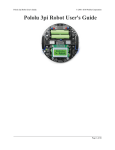
Pololu 3pi Robot User's Guide
© 2001–2009 Pololu Corporation
Pololu 3pi Robot User's Guide
Page 1 of 56
Pololu 3pi Robot User's Guide
1. Introduction . . . . . . . . . . . . . . . . . . . . . . .
2. Contacting Pololu . . . . . . . . . . . . . . . . . . . .
3. Important Safety Warning and Handling Precautions .
4. Getting Started with Your 3pi Robot . . . . . . . . . .
4.a. What You Will Need . . . . . . . . . . . . . .
4.b. Powering Up Your 3pi . . . . . . . . . . . . .
4.c. Using the Preloaded Demo Program . . . . . .
4.d. Included Accessories . . . . . . . . . . . . . .
5. How Your 3pi Works . . . . . . . . . . . . . . . . . .
5.a. Batteries . . . . . . . . . . . . . . . . . . . . .
5.b. Power management . . . . . . . . . . . . . . .
5.c. Motors and Gearboxes . . . . . . . . . . . . .
5.d. Digital inputs and sensors . . . . . . . . . . . .
5.e. 3pi Simplified Schematic Diagram . . . . . . .
6. Programming Your 3pi . . . . . . . . . . . . . . . . .
6.a. Downloading and Installing the C/C++ Library
6.b. Compiling a Simple Program . . . . . . . . . .
7. Example Project #1: Line Following . . . . . . . . . .
7.a. About Line Following . . . . . . . . . . . . . .
7.b. A Simple Line-Following Algorithm for 3pi . .
7.c. Advanced Line Following with 3pi: PID Control
8. Example Project #2: Maze Solving . . . . . . . . . . .
8.a. Solving a Line Maze . . . . . . . . . . . . . .
8.b. Working with Multiple C Files in AVR Studio .
8.c. Left Hand on the Wall . . . . . . . . . . . . . .
8.d. The Main Loop(s) . . . . . . . . . . . . . . . .
8.e. Simplifying the Solution . . . . . . . . . . . .
8.f. Improving the Maze Solving Code . . . . . . .
9. Pin Assignment Tables . . . . . . . . . . . . . . . . .
10. Expansion Information . . . . . . . . . . . . . . . .
10.a. Serial slave program . . . . . . . . . . . . . .
10.b. Serial master program . . . . . . . . . . . . .
10.c. Available I/O on the 3pi’s ATmega168 . . . .
11. Related Resources . . . . . . . . . . . . . . . . . . .
© 2001–2009 Pololu Corporation
.
.
.
.
.
.
.
.
.
.
.
.
.
.
.
.
.
.
.
.
.
.
.
.
.
.
.
.
.
.
.
.
.
.
.
.
.
.
.
.
.
.
.
.
.
.
.
.
.
.
.
.
.
.
.
.
.
.
.
.
.
.
.
.
.
.
.
.
.
.
.
.
.
.
.
.
.
.
.
.
.
.
.
.
.
.
.
.
.
.
.
.
.
.
.
.
.
.
.
.
.
.
.
.
.
.
.
.
.
.
.
.
.
.
.
.
.
.
.
.
.
.
.
.
.
.
.
.
.
.
.
.
.
.
.
.
.
.
.
.
.
.
.
.
.
.
.
.
.
.
.
.
.
.
.
.
.
.
.
.
.
.
.
.
.
.
.
.
.
.
.
.
.
.
.
.
.
.
.
.
.
.
.
.
.
.
.
.
.
.
.
.
.
.
.
.
.
.
.
.
.
.
.
.
.
.
.
.
.
.
.
.
.
.
.
.
.
.
.
.
.
.
.
.
.
.
.
.
.
.
.
.
.
.
.
.
.
.
.
.
.
.
.
.
.
.
.
.
.
.
.
.
.
.
.
.
.
.
.
.
.
.
.
.
.
.
.
.
.
.
.
.
.
.
.
.
.
.
.
.
.
.
.
.
.
.
.
.
.
.
.
.
.
.
.
.
.
.
.
.
.
.
.
.
.
.
.
.
.
.
.
.
.
.
.
.
.
.
.
.
.
.
.
.
.
.
.
.
.
.
.
.
.
.
.
.
.
.
.
.
.
.
.
.
.
.
.
.
.
.
.
.
.
.
.
.
.
.
.
.
.
.
.
.
.
.
.
.
.
.
.
.
.
.
.
.
.
.
.
.
.
.
.
.
.
.
.
.
.
.
.
.
.
.
.
.
.
.
.
.
.
.
.
.
.
.
.
.
.
.
.
.
.
.
.
.
.
.
.
.
.
.
.
.
.
.
.
.
.
.
.
.
.
.
.
.
.
.
.
.
.
.
.
.
.
.
.
.
.
.
.
.
.
.
.
.
.
.
.
.
.
.
.
.
.
.
.
.
.
.
.
.
.
.
.
.
.
.
.
.
.
.
.
.
.
.
.
.
.
.
.
.
.
.
.
.
.
.
.
.
.
.
.
.
.
.
.
.
.
.
.
.
.
.
.
.
.
.
.
.
.
.
.
.
.
.
.
.
.
.
.
.
.
.
.
.
.
.
.
.
.
.
.
.
.
.
.
.
.
.
.
.
.
.
.
.
.
.
.
.
.
.
.
.
.
.
.
.
.
.
.
.
.
.
.
.
.
.
.
.
.
.
.
.
.
.
.
.
.
.
.
.
.
.
.
.
.
.
.
.
.
.
.
.
.
.
.
.
.
.
.
.
.
.
.
.
.
.
.
.
.
.
.
.
.
.
.
.
.
.
.
.
.
.
.
.
.
.
.
.
.
.
.
.
.
.
.
.
.
.
.
.
.
.
.
.
.
.
.
.
.
.
.
.
.
.
.
.
.
.
.
.
.
.
.
.
.
.
.
.
.
.
.
.
.
.
.
.
.
.
.
.
.
.
.
.
.
.
.
.
.
.
.
.
.
.
.
.
.
.
.
.
.
.
.
.
.
.
.
.
.
.
.
.
.
.
.
.
.
.
.
.
.
.
.
.
.
.
.
.
.
.
.
.
.
.
.
.
.
.
.
.
.
.
.
.
.
.
.
.
.
.
.
.
.
.
.
.
.
.
.
.
.
.
.
.
.
.
.
.
.
.
.
.
.
.
.
.
.
.
.
.
.
.
.
.
.
.
.
.
.
.
.
.
.
.
.
.
.
.
.
.
.
.
.
.
.
.
.
.
.
.
.
.
.
.
.
.
.
.
.
.
.
.
.
.
.
.
.
.
.
.
.
.
.
.
.
.
.
.
.
.
.
.
.
.
.
.
.
.
.
.
.
.
.
.
.
.
.
.
.
.
.
.
.
.
.
.
.
.
.
.
.
.
.
.
.
.
.
.
.
.
.
.
.
.
.
.
.
.
.
.
.
.
.
.
.
.
.
.
.
.
.
.
.
.
.
.
.
.
.
.
.
.
.
.
.
.
.
.
.
.
.
.
.
.
.
.
.
.
.
.
.
.
.
.
.
.
.
.
.
.
.
.
.
.
.
.
.
.
.
.
.
.
.
.
.
.
.
.
.
.
.
.
.
.
.
.
.
.
.
.
.
.
.
.
.
.
.
.
.
.
.
.
.
.
.
.
.
.
.
.
.
.
.
.
.
.
.
.
.
.
.
.
.
.
.
.
.
.
.
.
.
.
.
.
.
.
.
.
.
.
.
.
.
.
.
.
.
.
.
.
.
.
.
.
.
.
.
.
.
.
.
.
.
.
.
.
.
.
.
.
.
.
.
.
.
.
.
.
.
.
.
.
.
.
.
.
.
.
.
.
.
.
.
.
.
.
Page 2 of 56
3
4
5
6
6
7
7
8
9
9
10
12
14
16
18
18
19
23
23
23
28
30
30
30
32
33
35
38
39
42
42
50
54
56
Pololu 3pi Robot User's Guide
© 2001–2009 Pololu Corporation
1. Introduction
The Pololu 3pi robot is a small, high-performance, autonomous robot designed to excel in line-following and line-mazesolving competitions. Powered by four AAA batteries (not included) and a unique power system that runs the motors at
a regulated 9.25 V, 3pi is capable of speeds up to 100 cm/second while making precise turns and spins that don’t vary
with the battery voltage. This results in highly consistent and repeatable performance of well-tuned code even as the
batteries run low. The robot comes fully assembled with two micro metal gearmotors, five reflectance sensors, an 8×2
character LCD, a buzzer, three user pushbuttons, and more, all connected to a user-programmable AVR microcontroller.
The 3pi measures approximately 3.7 inches (9.5 cm) in diameter and weighs 2.9 oz (83 g) without batteries.
The 3pi is based on an Atmel ATmega168 microcontroller running at 20 MHz with 16KB of flash program memory and
1KB data memory. The use of the ATmega168 microcontroller makes the 3pi compatible with the popular Arduino
development platform. Free C and C++ development tools are also available, and an extensive set of libraries make it a
breeze to interface with all of the integrated hardware. Sample programs are available to show how to use the various
3pi components, as well as how to perform more complex behaviors such as line following and maze solving.
Please
note
that
an
external
AVR
ISP
programmer,
such
as
Programmer [http://www.pololu.com/catalog/product/740] is required to program the 3pi robot.
our
Orangutan
USB
You can download a pdf version of this user’s guide here [http://www.pololu.com/file/download/3pi.pdf?file_id=0J169]
(2017k pdf). For a Spanish version of this document, please see Pololu 3pi Robot Guia
Usuario [http://www.pololu.com/file/download/Pololu3piRobotGuiaUsuario.pdf?file_id=0J137] (2483k pdf) (provided by
customer Jaume B.).
1. Introduction
Page 3 of 56
Pololu 3pi Robot User's Guide
© 2001–2009 Pololu Corporation
2. Contacting Pololu
You can check the 3pi product page [http://www.pololu.com/catalog/product/975] for additional information, including
pictures, videos, example code, and other resources.
We would be delighted to hear from you about any of your projects and about your experience with the 3pi robot. You
can contact us [http://www.pololu.com/contact] directly or post on our forum [http://forum.pololu.com/]. Tell us what we did
well, what we could improve, what you would like to see in the future, or share your code with other 3pi users.
2. Contacting Pololu
Page 4 of 56
Pololu 3pi Robot User's Guide
© 2001–2009 Pololu Corporation
3. Important Safety Warning and Handling Precautions
The 3pi robot is not intended for young children! Younger users should use this product only under adult supervision.
By using this product, you agree not to hold Pololu liable for any injury or damage related to the use or to the
performance of this product. This product is not designed for, and should not be used in, applications where the
malfunction of the product could cause injury or damage. Please take note of these additional precautions:
• Do not attempt to program your 3pi if its batteries are drained or uncharged. Losing power during programming
could permanently disable your 3pi. If you have purchased rechargeable batteries for use with the 3pi, do not
assume they come fully charged; charge them before you first use them. The 3pi has the ability to monitor its
battery voltage; the example line-following and maze-solving programs we provide show how to use this feature,
and you should include it in your programs so you can know when its time to recharge or replace your batteries.
• The 3pi robot contains lead, so follow appropriate handling procedures, such as not licking the robot and
washing hands after handling.
• The 3pi robot is intended for use indoors on relatively flat, smooth surfaces. Avoid running your 3pi on surfaces
that might scrape or damage the underside of your robot’s PCB as it drives around.
• Avoid placing the robot so that the underside of the PCB makes contact with conductive materials (e.g. do not
place the 3pi in a bin filled with metal parts). This could inadvertently short out the batteries and damage your
robot, even with the 3pi turned off. Shorting various pads or components together could also damage your 3pi.
• Since the PCB and its components are exposed, take standard precautions to protect your 3pi robot from ESD
(electrostatic discharge), which could damage the on-board electronics. When picking up the 3pi, you should
first touch a safe part of the robot such as the wheels, motors, batteries, or the edges of the PCB. If you first
touch components on the PCB, you risk discharging through them. When handing the 3pi to another person, first
touch their hand with your hand to equalize any charge imbalance between you so that you don’t discharge
through the 3pi as the exchange is made.
• If you remove the LCD, take care to replace it in the right orientation such that it is over the rear battery back. It
is possible to put the LCD in backwards or offset; doing so could damage the LCD or the 3pi.
3. Important Safety Warning and Handling Precautions
Page 5 of 56
Pololu 3pi Robot User's Guide
© 2001–2009 Pololu Corporation
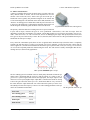
4. Getting Started with Your 3pi Robot
Getting started with your 3pi can be as simple as taking it out of the box, adding batteries, and turning it on. The 3pi
ships with a demo program that will give you a brief tour of its features.
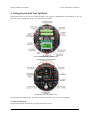
General features of the Pololu 3pi robot, top view.
Labeled bottom view of the Pololu 3pi robot.
The following subsections will give you all the information you need to get your 3pi up and running!
4.a. What You Will Need
The following materials are necessary for getting started with your 3pi:
4. Getting Started with Your 3pi Robot
Page 6 of 56
Pololu 3pi Robot User's Guide
© 2001–2009 Pololu Corporation
• 4 AAA batteries. Any AAA cells will work, but we recommend NiMH batteries, which are rechargeable and
can be purchased from Pololu [http://www.pololu.com/catalog/product/1002] or at a local store. If you use rechargeable
batteries, you will also need a battery charger. Battery chargers designed to connect to external series battery
packs may be used with the 3pi’s battery charger port.
• AVR ISP programmer with 6-pin connector. The 3pi features an ATmega168 microcontroller, which requires
an external programmer such as the Pololu Orangutan USB programmer [http://www.pololu.com/catalog/product/
740] or Atmel’s AVRISP series. The 3pi has a standard 6-pin programming connector, so your programmer will
need to have a 6-pin ISP cable [http://www.pololu.com/catalog/product/972] for connecting to the target device. (You
will also need whatever cable your programmer requires to connect to a computer. Our Orangutan USB
programmer requires a USB cable [http://www.pololu.com/catalog/product/130] that is not included with the
programmer alone but is included as part of the 3pi+programmer combo deal [http://www.pololu.com/catalog/
product/747]).
• A desktop or laptop computer. You will need a personal computer for developing your code and loading it
onto the 3pi. The 3pi can be programmed on Windows, Mac, and Linux operating systems, but Pololu support
for Macs is limited.
You might find the following materials useful in creating an environment for your robot to explore:
• Several large sheets of white posterboard (available at crafts or office supply stores) or dry-erase whiteboard
stock (commonly available at home/construction supply stores).
• Light-colored masking tape for joining multiple sheets together.
• 3/4" black electrical tape to create lines for your robot to follow.
4.b. Powering Up Your 3pi
The first step in using your new 3pi robot is to insert four AAA batteries into the battery
holders. To do this you will need to remove the LCD. Pay attention to the LCD’s
orientation as you will want to plug it back in this way when you are done. With the
LCD removed your 3pi should look like the picture to the right.
Once the batteries are in place, you should return the LCD to its position over the rear
battery holder. Make sure each male LCD header pin goes into a corresponding female
socket.
Next, push the power button (located on the left side of the rear battery pack) to turn on
your 3pi. You should see the two blue power LEDs on the underside of the 3pi light,
and the 3pi should begin running its preloaded demo program. You can simply push the power button again to turn the
3pi off, and you can push the reset button (located just below the power button) to reset the program the robot is
running.
4.c. Using the Preloaded Demo Program
Your 3pi comes preloaded with a program that demonstrates most of its features and allows you to test that it is working
correctly. When you first turn on your 3pi, you will hear a beep and see the words “Pololu 3pi Robot”, then “Demo
Program” appear, indicating that you are running the demo program. If you hear a beep but do not see any text on the
LCD, you may need to adjust the contrast potentiometer on the underside of the board. When the program has started
successfully, press the B button to proceed to the main menu. Press C or A to scroll forward or backward through the
menu, and press B to make a selection or to exit one of the demos. There are seven demos accessible from the menu:
1. Battery: This demo displays the battery voltage in millivolts, which should be above 5000 (5.0 Volts) for a
fully-charged set of batteries. Removing the jumper marked ADC6 will separate the battery voltage
measurement circuit from the analog input, causing the number displayed to drop to some low value.
4. Getting Started with Your 3pi Robot
Page 7 of 56
Pololu 3pi Robot User's Guide
© 2001–2009 Pololu Corporation
2. LEDs: Blinks the red and green user LEDs on the underside of the board. If you have soldered in the optional
user LEDs, they will also blink.
3. Trimpot: Displays the position of the user trimmer potentiometer, which is located on the underside of the
board, as a number between 0 and 1023. While displaying the value, this demo also blinks the LEDs and plays a
note whose frequency is a function of the current reading. It is easiest to turn the trimpot using a 2mm flat-head
screwdriver.
4. Sensors: Show the current readings of the IR sensors using a bar graph. Bigger bars mean lower reflectance.
Placing a reflective object such as your finger under one of the sensors will cause the corresponding reading to
drop visibly on the graph. This demo also displays “C” to indicate that button C has an effect—press C and the
IR emitters will be turned off. In indoor lighting conditions away from bright incandescent or halogen lights, all
of the sensors should return entirely black readings with IR off. Removing the jumper marked PC5 disables
control of the emitters, causing them to always be on.
5. Motors: Hold down A or C to run the motor on the corresponding side, or hold down both buttons to run both
motors simultaneously. The motors will gradually ramp up to speed; in your own programs, you can switch them
on much more suddenly. Tap A or C to switch the corresponding motor to reverse (the button letter becomes
lowercase if pressing it will drive the corresponding motor in reverse).
6. Music: Plays an adaptation of J. S. Bach’s Fugue in D Minor for microcontroller and piezo, while scrolling a
text display. This demonstrates the ability of the 3pi to play music in the background.
7. Timer: A simple stopwatch. Press C to start or stop the stopwatch and A to reset. The stopwatch continues to
count while you are exploring the other demos.
The source code for the demo program is included with the Pololu AVR C/C++ Library described in Section 6. After
downloading and unpacking the library zip file, the demo program can be found in the folder examples\3pi-demoprogram.
4.d. Included Accessories
The 3pi robot ships with two through-hole red LEDs and two through-hole green LEDs.
There are connection points for three optional LEDs on your 3pi: one next to the power
button to indicate when the 3pi is on and two user-controllable LED ports near the front
edge of the robot. Using these LEDs is completely optional as the 3pi will function just
fine without them. You can customize your 3pi by choosing your desired combination
of red and green LEDs, or you can even use your own
LEDs [http://www.pololu.com/catalog/category/20] if you want more color/brightness options.
Note that you should only add LEDs if you are comfortable soldering, and you should take care to avoid desoldering
any of the components near the through-hole LED pads. LEDs are polarized, so be sure to solder them such that the
longer lead connects to the pad marked with the +. Before you solder them in you can press-fit them in place and check
to make sure they light as expected. Once soldered in place, carefully trim off the excess portion of the LED leads.
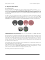
Your 3pi also ships with three shorting blocks of each color: blue, red, yellow, black. This means you can customize
your 3pi by selecting the shorting block color you most prefer, or you can use a mixture of colors!
4. Getting Started with Your 3pi Robot
Page 8 of 56
Pololu 3pi Robot User's Guide
© 2001–2009 Pololu Corporation
5. How Your 3pi Works
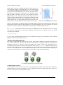
5.a. Batteries
Introduction to Batteries
The power system on the 3pi begins with the batteries, so it is important to
understand how your batteries work. A battery contains a carefully controlled
chemical reaction that pulls electrons in from the positive (+) terminal and pushes
them out of the negative (-) terminal. The most common type is the alkaline
battery, which is based on a reaction between zinc and manganese through a
potassium hydroxide solution. Once alkaline batteries are completely discharged,
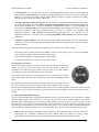
they cannot be reused. For the 3pi, we recommend rechargeable nickel-metalhydride (NiMH) batteries, which can be recharged over and over. NiMH batteries Two rechargeable AAA Ni-MH batteries.
are based on a different chemical reaction from alkaline batteries, but you don’t
need to know anything about the chemical details to use a battery: everything you
need to know about it is measured with a few simple numbers. The first is the strength with which the electrons are
pushed, which we measure in volts (V), the units of electric potential. An NiMH battery has a voltage of about 1.2 V. To
understand how much power you can get out of a battery, you also need to know how many electrons the battery can
push per second – this is the electric current, measured in amps (A). A current of 1 A corresponds to about 6×10¹⁸
electrons flowing out one side and in to the other each second, which is such a huge number that it’s easier to talk about
it just in terms of amps. 1 A is also a typical current that a medium-sized motor might use, and it’s a current that will put
a significant strain on small (AAA) batteries.
For any battery, if you attempt to draw more and more current, the voltage produced by the battery will drop, eventually
dropping all the way to zero at the short circuit current: the current that flows if you connect one side directly to the
other with a thick wire. (Don’t try this! The wire might overheat and melt, and the battery could explode.) The following
graph shows a good model of how the voltage on a typical battery drops as the current goes up:
Battery voltage vs. current.
The power put out by a battery is measured by multiplying the volts by the amps, giving a measurement in watts (W).
For example, at the point marked in the graph, we have a voltage of 0.9 V and a current of 0.6 A, this means that the
power output is 0.54 W. If you want more power, you need to add more batteries, and there are two ways to do it:
parallel and series configurations. When batteries are connected in parallel, with all of their positive terminals tied
together and all of their negative terminals tied together, the voltage stays the same, but the maximum current output is
multiplied by the number of batteries. When they are connected in series, with the positive terminal of one connected to
the negative terminal of the next, the maximum current stays the same while the voltage multiplies. Either way, the
maximum power output will be multiplied by the number of batteries. Think about two people using two buckets to lift
water from a lake to higher ground. If they stand next to each other (working in parallel), they will be able to lift the
water to the same height as before, while delivering twice the amount of water. If one of them stands uphill from the
other, they can work together (in series) to life the water twice as high, but at the same rate as a single person.
5. How Your 3pi Works
Page 9 of 56
Pololu 3pi Robot User's Guide
© 2001–2009 Pololu Corporation
In practice, we only connect batteries in series. This is because different batteries will always have slightly different
voltages, and if they are connected in parallel, the stronger battery will deliver current to the weaker battery, wasting
power even when there is nothing else in the circuit. If we want more current, we can use bigger batteries: AAA, AA, C,
and D batteries of the same type all have the same voltage, but they can put out very different amounts of current.
The total amount of energy in any battery is limited by the chemical reaction: once the chemicals are exhausted, the
battery will stop producing power. This happens gradually: the voltage and current produced by a battery will steadily
drop until the energy runs out, as shown in the graph below:
Battery voltage vs. time.
A rough measure of the amount of energy stored in a battery is given by its milliamp-hour (mAH) rating, which
specifies how long the battery will last at a given discharge rate. The mAH rating is the discharge rate multiplied by how
long the battery lasts: if you draw current at a rate of 200 mA (0.2 A), and the battery lasts for 3 hours, you would call it
a 600 mAH battery. If you discharge the same battery at 600 mA, you would get about an hour of operation (however,
battery capacity tends to decline with faster discharge rates, so you might only get 50 minutes).
Note: If you have purchased rechargeable batteries for the 3pi, you should fully charge them before you first
use them. You should never attempt to program your 3pi if its batteries are drained or uncharged. Losing
power during programming could permanently disable your 3pi.
5.b. Power management
Battery voltage drops as the batteries are used up, but many electrical components require a specific voltage. A special
kind of component called a voltage regulator helps out by converting the battery voltage to a constant, specified voltage.
For a long time, 5 V has been the most common regulated voltage used in digital electronics; this is also called TTL
level. The microcontroller and most of the circuitry in the 3pi operate at 5 V, so voltage regulation is essential. There are
two basic types of voltage regulators:
• Linear regulators use a simple feedback circuit to vary how much energy is passed through and how much is
discarded. The regulator produces a lower output voltage by dumping unneeded energy. This wasteful,
inefficient approach makes linear regulators poor choices for applications that have a large difference between
the input and output voltages, or for applications that require a lot of current. For example, 15 V batteries
regulated down to 5 V with a linear regulator will lose two-thirds of their energy in the linear regulator. This
energy becomes heat, so linear regulators often need large heat sinks, and they generally don’t work well with
high-power applications.
• Switching regulators turn power on and off at a high frequency, filtering the output to produce a stable supply at
the desired voltage. By carefully redirecting the flow of electricity, switching regulators can be much more
efficient than linear regulators, especially for high-current applications and large changes in voltage. Also,
switching regulators can convert low voltages into higher voltages! A key component of a switching regulator is
the inductor, which stores energy and smooths out current; on the 3pi, the inductor is the gray block near the ball
5. How Your 3pi Works
Page 10 of 56
Pololu 3pi Robot User's Guide
© 2001–2009 Pololu Corporation
caster labeled “100”. A desktop computer power supply also uses switching regulators: peek through the vent in
the back of your computer and look for a donut-shaped piece with a coil of thick copper wire wrapped around it
– that’s the inductor.
The power management subsystem built into the 3pi is shown in this block diagram:
The voltage of 4 x AAA cells can vary between 3.5 – 5.5 V (and even to 6 V if alkalines are used). This means it’s not
possible simply to regulate the voltage up or down to get 5 V. Instead, in the 3pi, a switching regulator first boosts the
battery voltage up to 9.25 V (Vboost), and a linear regulator regulates Vboost back down to 5 V (VCC). Vboost powers
the motors and the IR LEDs in the line sensors, while VCC is used for the microcontroller and all digital signals.
Using Vboost for the motors and sensors gives the 3pi three unique performance advantages over typical robots, which
use battery power directly:
• First, a higher voltage means more power for the motors, without requiring more current and a larger motor
driver.
• Second, since the voltage is regulated, the motors will run the same speed as the batteries drop from 5.5 down to
3.5 V. You can take advantage of this when programming your 3pi, for example by calibrating a 90° turn based
on the amount of time that it takes.
• Third, at 9.25 V, all five of the IR LEDs can be powered in series so that they consume the lowest possible
amount of power. (Note that you can switch the LEDs on and off to save even more power.)
One other interesting thing about this power system is that instead of gradually running out of power like most robots,
the 3pi will operate at maximum performance until it suddenly shuts off. This can take you by surprise, so you might
want your 3pi to monitor its battery voltage.
A simple circuit for monitoring battery voltage is built in to the 3pi. Three resistors, shown in
the circuit at right, comprise a voltage divider that outputs a voltage equal to two-thirds of the
battery voltage, which will always be safely below the main microcontroller’s maximum analog
input voltage of 5 V. For example, at a battery voltage of 4.8 V, the battery voltage monitor port
ADC6 will be at a level of 3.2 V. Using 10-bit analog-to-digital conversion, where 5 V is read
as a value of 1023, 3.2 V is read as a value of 655. To convert it back to the actual battery
voltage, multiply this number by 5000 mV×3/2 and divide by 1023. This is handled
conveniently by the read_battery_millivolts() function (provided in the Pololu AVR
Library; see Section 6.a for more information), which averages ten samples and returns the
battery voltage in mV:
unsigned int read_battery_millivolts()
{
return readAverage(6,10)*5000L*3/2/1023;
}
5. How Your 3pi Works
Page 11 of 56
Pololu 3pi Robot User's Guide
© 2001–2009 Pololu Corporation
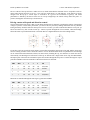
5.c. Motors and Gearboxes
A motor is a machine that converts electrical energy to motion. There are
many different kinds of motors, but the most important for low-cost
robotics is the brushed DC motor, which is the type used on the 3pi. A
brushed DC motor typically has permanent magnets on the outside and
several electromagnetic coils mounted on the motor shaft (armature). The
“brushes” are sliding pieces of metal that switch the power from one coil
to the next as the shaft turns so that magnetic attraction between the coil
and the magnets continuously pulls the motor in the same direction.
A typical small brushed DC motor, with no gearbox.
The primary values that describe a running motor are its speed, measured
in rpm, and its torque, measured in kg·cm or oz·in (pronounced “ounce-inches”). The units for torque show the
dependence on both force and distance; for example, a motor that produces 6 oz·in of torque can product a force of 6 oz.
with a 1-inch lever arm, 3 oz. with a 2-inch lever, and so on. Multiplying the torque and speed (measured at the same
time) give us the power delivered by a motor. We see, therefore, that a motor with twice the speed and half the torque as
another has the same power output.
Every motor has a maximum speed (when no force is applied) and a maximum torque (when the motor is completely
stopped). We call these the free-running speed and the stall torque. Naturally, a motor uses the least current when no
force is applied to it, and the current drawn from the batteries goes up until it stalls, so the free-running current and stall
current are also important parameters characterizing the motor. The stall current is usually much higher than the freerunning current, as shown in the graph below:
Motor operation: current and speed vs. torque.
The free-running speed of a small DC motor is usually many thousands of rotations per
minute (rpm), much high than the speed we want the wheels of a robot to turn. A
gearbox is a system of gears that converts the high-speed, low-torque output of the
motor into a lower-speed, higher-torque output that is a much better suited for driving
a robot. The gear ratio used on the 3pi is 30:1, which means that for every 30 turns of
the motor shaft, the output shaft turns once. This reduces the speed by a factor of 30,
and (ideally) increases the torque by a factor of 30. The resulting parameters of the 3pi
motors are summarized in this table:
Gear ratio:
30:1
Free-running speed:
700 rpm
Free-running current:
60 mA
Stall torque:
6 oz·in
Stall current:
540 mA
5. How Your 3pi Works
The 30:1 gearmotor used on the 3pi.
Page 12 of 56
Pololu 3pi Robot User's Guide
© 2001–2009 Pololu Corporation
The two wheels of the 3pi each have a radius of 0.67 in, which means that the maximum force it can produce with two
motors when driving forward is 2×6/0.67 = 18 oz. The 3pi weighs about 7 oz with batteries, so the motors are strong
enough to lift the 3pi up a vertical slope or accelerate it at 2 g (twice the acceleration of gravity). The actual
performance is limited by the friction of the tires: on a steep enough slope, the wheels will slip before they stall – in
practice, this happens when the slope is around 30-40°.
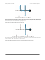
Driving a motor with speed and direction control
One nice thing about a DC motor is that you can change the direction of rotation by switching the polarity of the applied
voltage. If you have a loose battery and motor, you can see this for yourself by making connections one way and then
turning the battery around to make the motor spin in reverse. Of course, you don’t want take the batteries out of your 3pi
and reverse them every time it needs to back up – instead, a special arrangement of four switches, called an H-bridge,
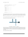
allows the motor to spin either backwards or forwards. Here is a diagram that shows how the H-bridge works:
If switches 1 and 4 are closed (the center picture), current flows through the motor from left to right, and the motor spins
forward. Closing switches 2 and 3 causes the current to reverse direction and the motor to spin backward. An H-bridge
can be constructed with mechanical switches, but most robots, including the 3pi, use transistors to switch the current
electronically. The H-bridges for both motors on the 3pi are all built into a single motor driver chip, the TB6612FNG,
and output ports of the main microcontroller operate the switches through this chip. Here is a table showing how output
ports PD5 and PD6 on the microcontroller control the transistors of motor M1:
PD5
PD6
1
2
3
4
M1
0
0
off
off
off
off
off (coast)
0
1
off
on
on
off
forward
1
0
on
off
off
on
reverse
1
1
off
off
on
on
off (brake)
Motor M2 is controlled through the same logic by ports PD3 and PB3:
PD3
PB3
1
2
3
4
M2
0
0
off
off
off
off
off (coast)
0
1
off
on
on
off
forward
1
0
on
off
off
on
reverse
1
1
off
off
on
on
off (brake)
5. How Your 3pi Works
Page 13 of 56
Pololu 3pi Robot User's Guide
© 2001–2009 Pololu Corporation
Speed control is achieved by rapidly switching the motor between two
states in the table. Suppose we keep PD6 high (at 5 V, also called a logical
“1”) and have PD5 alternate quickly between low (0 V or “0”) and high.
The motor driver will switch between the “forward” and “brake” states,
causing M1 to turn forward at a reduced speed. For example, if PD6 is
high two thirds of the time (a 67% duty cycle), then M1 will turn at
approximately 67% of its full speed. Since the motor voltage is a series of
pulses of varying width, this method of speed control is called pulse-width
modulation (PWM). An example series of PWM pulses is shown in the
graph at right: as the size of the pulses decreases from 100% duty cycle
down to 0%, the motor speed decreases from full speed down to a stop.
PWM speed control, showing gradual deceleration.
In the 3pi, speed control is accomplished using special PWM outputs of the main microcontroller that are linked to the
internal timers Timer0 and Timer2. This means that you can set the PWM duty cycle of the two motors once, and the
hardware will continue to produce the PWM signal, in the background, without any further attention.
The set_motors() function in the Pololu AVR Library (see Section 6.a for more information) lets you set the duty
cycle, and it uses 8-bit precision: a value of 255 corresponds to 100% duty cycle. For example, to get 67% on M1 and
33% on M2, you would call
set_motors(171,84);
To get a slowly decreasing PWM sequence like the one shown in the graph, you would need to write a loop that
gradually decreases the motor speed over time.
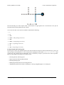
Turning with a differential drive
The 3pi has an independent motor and wheel on each side, which enables a method of locomotion called differential
drive. It is also known as a “tank drive” since this is how a tank drives. It is completely unlike the steering system of
automobile, which uses a single drive motor and steerable front wheels. Turning with a differential drive is
accomplished by running the two motors at different speeds. In the previous set_motors() example, the left wheel will
spin faster than the right, driving the robot forward and to the right. The difference in speeds determines how sharp the
turn will be, and spinning in place can be accomplished by running one motor forward and one backward. Spinning is an
especially effective maneuver for a round robot, and you won’t have to worry about parallel parking!
The 3pi demonstrating the effects of various motor settings.
5.d. Digital inputs and sensors
The microcontroller at the heart of the 3pi, an Atmel AVR mega168, has a number of pins which can be configured as
digital inputs: they are read by your program as a 1 or a 0 depending on whether the voltage is high (above about 2 V) or
low. Here is the circuit for one of the pushbutton inputs:
5. How Your 3pi Works
Page 14 of 56
Pololu 3pi Robot User's Guide
© 2001–2009 Pololu Corporation
Normally, the pull-up resistor R (20-50 k) brings the voltage on the input pin to 5 V, so it reads as a 1, but pressing the
button connects the input to ground (0 V) through a 1 k resistor, which is much lower than the value of R. This brings
the input voltage very close to 0 V, so the pin reads as a 0. Without the pull-up resistor, the input would be “floating”
when the button is not pressed, and the value read could be affected by residual voltage on the line, interference from
nearby electrical signals, or even distant lightning. Don’t leave an input floating unless you have a good reason. Since
the pull-up resistors are important, they are included within the AVR – the resistor R in the picture represents this
internal pull-up, not a discrete part on the 3pi circuit board.
A more complicated use for the digital inputs is in the reflectance sensors. Here is the circuit for the 3pi’s leftmost
reflectance sensor, which is connected to pin PC0:
The sensing element of the reflectance sensor is the phototransistor shown in the left half of U4, which is connected in
series with capacitor C21. A separate connection leads through resistor R12 to pin PC0. This circuit takes advantage of
the fact the digital inputs of the AVR can be reconfigured as digital outputs on the fly. A digital output presents a
voltage of 5 V or 0 V, depending on whether it is set to a 1 or a 0 by your program. The way it works is that the pin is
alternately set to a 5 V output and then a digital input. The capacitor stores charge temporarily, so that the input reads as
a 1 until most of the stored charge has flowed through the phototransistor. Here is an oscilloscope trace showing the
voltage on the capacitor (yellow) dropping as its charge flows through the phototransistor, and the resulting digital input
value of pin PC0 (blue):
The rate of current flow through the phototransistor depends on the light level, so that when the robot is over a bright
white surface, the value returns to 0 much more quickly than when it is over a black surface. The trace shown above was
taken when the sensor was on the edge between a black surface and a white one – this is what it looks like on pure
white:
5. How Your 3pi Works
Page 15 of 56
Pololu 3pi Robot User's Guide
© 2001–2009 Pololu Corporation
The length of time that the digital input stays at 1 is very short when over white, and very long when over black. The
function read_line_sensors() in the Pololu AVR Library switches the port as described above and returns the time for
each of the five sensors. Here is a simplified version of the code that reads the sensors:
time = 0;
last_time = TCNT2;
while (time < _maxValue)
{
// Keep track of the total time.
// This implicity casts the difference to unsigned char, so
// we don't add negative values.
unsigned char delta_time = TCNT2 - last_time;
time += delta_time;
last_time += delta_time;
// continue immediately if there is no change
if (PINC == last_c)
continue;
// save the last observed values
last_c = PINC;
}
// figure out which pins changed
for (i = 0; i < _numSensors; i++)
{
if (sensor_values[i] == 0 && !(*_register[i] & _bitmask[i]))
sensor_values[i] = time;
}
This piece of code is found in the file src\PololuQTRSensors\PololuQTRSensors.cpp. The code makes use of timer
TCNT2, which is a special register in the AVR that we have configured to count up continuously, incrementing every
0.4 μs. Basically, the code waits until one of the sensors changes value, counting up the elapsed time in the variable
time. (It is important to use a separate variable for the elapsed time since the timer TCNT2 periodically overflows,
dropping back to zero.) Upon detecting a transition from a 1 to a 0 on one of the sensors (by measuring a change in the
input port PINC), the code determines which sensor changed and records the time in the array sensor_values[i]. After
the time limit _maxValue is reached (this is set to 2000 by default on the 3pi, corresponding to 800 μs), the loop ends,
and the time values are returned.
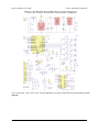
5.e. 3pi Simplified Schematic Diagram
A full understanding of how your 3pi works cannot be achieved without first understanding its schematic diagram:
5. How Your 3pi Works
Page 16 of 56
Pololu 3pi Robot User's Guide
© 2001–2009 Pololu Corporation
You can download a pdf version of the schematic here [http://www.pololu.com/file/download/3pi_schematic.pdf?file_id=0J119]
(40k pdf).
5. How Your 3pi Works
Page 17 of 56
Pololu 3pi Robot User's Guide
© 2001–2009 Pololu Corporation
6. Programming Your 3pi
To do more with your 3pi than explore the demo program, you will need to program it, which requires an external AVR
ISP programmer such as our Orangutan USB programmer [http://www.pololu.com/catalog/product/740]. Your first step
should be to set up your programmer by following its installation instructions. If you are using the Orangutan USB
programmer, please see its user’s guide [http://www.pololu.com/docs/0J6].
Next you will need software that can compile your programs and transfer them to your 3pi via your programmer. We
recommend you download two software packages for this:
1. WinAVR [http://winavr.sourceforge.net/], a free, open-source suite of development tools for the AVR family of
microcontrollers, including the GNU GCC compiler for C/C++.
2. AVR Studio [http://www.atmel.com/avrstudio/], Atmel’s free integrated development environment (IDE) that
natively works with WinAVR’s free GCC C/C++ compiler. AVR Studio includes AVR ISP software that will let
you upload your programs to the 3pi.
Note: You can also program your 3pi using the Arduino IDE and an external ICSP programmer, such as our
Orangutan USB programmer. For instructions on this approach, please see our guide: Programming
Orangutans and the 3pi Robot from the Arduino Environment [http://www.pololu.com/docs/0J17]. The rest of
this guide will be based on AVR Studio.
For more general instructions on using the Pololu C/C++ libraries with our AVR-based robot boards, including Linux
installation instructions, see the Pololu AVR C/C++ Library User’s Guide [http://www.pololu.com/docs/0J20].
Warning: Do not attempt to program your 3pi if its batteries are drained or uncharged (make sure you charge
any new rechargeable batteries fully before you first use them). Losing power during programming could
permanently disable your 3pi.
6.a. Downloading and Installing the C/C++ Library
The Pololu C/C++ AVR Library makes it easy for you to use the advanced features of your 3pi; the library is used for
all of the examples in the following sections. For your convenience, the source code for these examples and the demo
program is included with the library. To begin the installation process for the Pololu AVR C/C++ Library, you will need
to download the zip file:
• Pololu AVR Library [http://www.pololu.com/file/download/libpololu-avr-090414.zip?file_id=0J191] (877k zip) released
2009-04-14
Open the .zip file and click “Extract all” to extract the Pololu AVR Library files. A directory called “libpololu-avr” will
be created. The automatic installation installs all Pololu AVR Library files in the location of your avr-gcc installation.
This is done by running install.bat or by opening a command prompt and typing “make install”.
Windows Vista: right click on install.bat and select “Run as administrator”.
If the automatic installation works, you can proceed to Section 6.b to try out some example programs on your 3pi.
6. Programming Your 3pi
Page 18 of 56
Pololu 3pi Robot User's Guide
© 2001–2009 Pololu Corporation
Note: To learn more about the functions in the Pololu AVR Library and how to use them, please see the
Pololu AVR Library Command Reference [http://www.pololu.com/docs/0J18].
Manual installation (optional: if the above instructions do not work)
Determine the location of your avr-gcc files. In Windows, they will usually be in a folder such as:
C:\WinAVR-20080610\avr. In Linux, the avr-gcc files are probably located in /usr/avr.
If you currently have an older version of the Pololu AVR Library, your first step should be to delete all of the old
include files and the libpololu.a file that you installed previously.
Next, copy libpololu.a into the lib subdirectory of your avr directory (e.g. C:\WinAVR-20080610\avr\lib). Note that
there is also a lib subdirectory directly below the main WinAVR directory; it will not work to put libpololu.a here.
Finally, copy the entire pololu subfolder into the include subfolder. The Pololu include files should now be located in
avr\include\pololu.
The Pololu AVR Library header files, installed correctly.
6.b. Compiling a Simple Program
A very simple demo program for the 3pi is available in the folder examples\atmega168\simple-test-3pi, using a few
basic commands from the Pololu AVR Library. Here is a copy of the source code:
#include <pololu/3pi.h>
int main()
{
print("Hello!");
play("L16 ceg>c");
while(1)
{
6. Programming Your 3pi
Page 19 of 56
Pololu 3pi Robot User's Guide
© 2001–2009 Pololu Corporation
red_led(0);
green_led(1);
delay_ms(100);
red_led(1);
green_led(0);
}
}
delay_ms(100);
return 0;
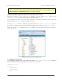
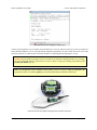
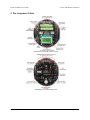
Navigate to the simple-test-3pi folder, double-click on the file
in AVR Studio, showing the C file.
test.aps,
and the project should open automatically
AVR Studio showing the 3pi sample program.
To compile this program, select Build > Build or press F7. Look for warnings and errors (indicated by yellow and red
dots) in the output displayed below. If the program compiles successfully, the message “Build succeeded with 0
Warnings…” will appear at the end of the output, and a file test.hex will have been created in the examples\simpletest-3pi\default folder.
6. Programming Your 3pi
Page 20 of 56
Pololu 3pi Robot User's Guide
© 2001–2009 Pololu Corporation
AVR Studio build window, compiling the example project.
Connect your programmer to your computer and to the ISP port of your 3pi, and turn on the 3pi’s power by pressing the
button labeled POWER. If you are using the Pololu Orangutan Programmer, the green status LED close to the USB
connector should be on, while the other two LEDs should be off, indicating that the programmer is ready.
Warning: Do not attempt to program your 3pi if its batteries are drained or uncharged (make sure you charge
any new rechargeable batteries fully before you first use them). Losing power during programming could
permanently disable your 3pi.
Note: Your programmer must be installed correctly before you use it. If you are using the Orangutan USB
programmer, please see its user’s guide [http://www.pololu.com/docs/0J6] for installation instructions.
Pololu 3pi robot with an Orangutan USB programmer connected to its ISP port.
6. Programming Your 3pi
Page 21 of 56
Pololu 3pi Robot User's Guide
© 2001–2009 Pololu Corporation
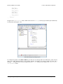
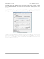
Select Tools > Program AVR > Connect to connect to the programmer. For the Orangutan Programmer, the default
options of “STK500 or AVRISP” and “Auto” should be fine, so click Connect and the AVRISP programming window
should appear.
You will use AVRISP to load test.hex into the flash memory of your 3pi. To do this, click “...” in the Flash section
and select file test.hex that was compiled earlier. Note that you have to first navigate to your project directory! Now
click “Program” in the Flash section, and the test code should be loaded onto your 3pi.
Programming the 3pi from AVR Studio.
If your 3pi was successfully programmed, you should hear a short tune, see the message “Hello!” on the LCD, and the
LEDs on the board should blink. If you hear the tune and see the lights flashing, but nothing appears on the LCD, make
sure that the LCD is correctly plugged in to the 3pi, and try adjusting the contrast using the small potentiometer on the
underside of the 3pi, closest to the ball caster.
6. Programming Your 3pi
Page 22 of 56
Pololu 3pi Robot User's Guide
© 2001–2009 Pololu Corporation
7. Example Project #1: Line Following
7.a. About Line Following
Now that you have learned how to compile a simple program for the 3pi, it’s time
to teach your robot do something more complicated. In this example project,
we’ll show you how to make your 3pi follow a black line on a white background,
by coordinating its sensors and motors. Line following is a great introduction to
robot programming, and it makes a great contest: it’s easy to build a linefollowing course, the rules are simple to understand, and it’s not hard to program
your 3pi to follow a line. Optimizing your program to make your 3pi zoom down
the line at the highest speed possible, however, is a challenge that can introduce
you to some advanced programming concepts.
Pololu 3pi robot on a 3/4" black line.
A great looking line following course can be constructed for a few dollars in a
couple of hours at home. For information on building your own course, see our
tutorial on Building Line Following and Line Maze Courses [http://www.pololu.com/docs/0J22].
7.b. A Simple Line-Following Algorithm for 3pi
A simple line following program for the 3pi is available in the folder examples\atmega168\3pi-linefollower.
Note: An Arduino-compatible version of this sample program can be downloaded as part of the Pololu
Arduino Libraries [http://www.pololu.com/docs/0J17] (see Section 5.g).
The source code demonstrates a variety of different features of the 3pi, including the line sensors, motors, LCD, battery
voltage monitor, and buzzer. The program has two phases.
The first phase of the program is the initialization and calibration phase, which is handled by the function intitialize().
This function is called once, at the beginning of the main() function, before anything else happens, and it takes care of
the following steps:
1. Calling pololu_3pi_init(2000) to set up the 3pi, with the sensor timeout set to 2000×0.4 us = 800 us. This means
that the sensor values will vary from 0 (completely white) to 2000 (completely black), where a value of 2000
indicates that the sensor’s capacitor took at least 800 us to discharge.
2. Displaying the battery voltage returned by the read_battery_millivolts() function. It is important to monitor
battery voltage so that your robot does not surprisingly run out of batteries and shut down during the middle of a
competition or during programming. For more information, see Section 3 of the command
reference [http://www.pololu.com/docs/0J18].
3. Calibrating the sensors. This is accomplished by turning the 3pi to the right and left on the line while calling the
calibrate_line_sensors() function. The minimum and maximum values read during this time are stored in RAM.
This allows the read_line_sensors_calibrated() function to return values that are adjusted to range from 0 to
1000 for each sensor, even if some of your sensors respond differently than the others. The read_line() function
used later in the code also depends on having calibrated values. For more information, see Section 12 of the
command reference [http://www.pololu.com/docs/0J18].
4. Displaying the calibrated line sensor values in a bar graph. This demonstrates the use of the
lcd_load_custom_character() function together with print_character() to make it easy to see whether the line
7. Example Project #1: Line Following
Page 23 of 56
Pololu 3pi Robot User's Guide
© 2001–2009 Pololu Corporation
sensors are working properly before starting the robot. For more information on this and other LCD commands,
see Section 5 of the command reference [http://www.pololu.com/docs/0J18].
5. Waiting for the user to press a button. It’s very important for your robot not to start driving until you want it to
start, or it could unexpectedly drive off of a table or out of your hands when you are trying to program it. We use
the button_is_pressed() function to wait for you to press the B button while displaying the battery voltage or
sensor readings. For more information on button commands, see Section 8 of the command
reference [http://www.pololu.com/docs/0J18].
In the second phase of the program, your 3pi will take a sensor reading and set the motor speed appropriately based on
the reading. The general idea is that if the robot is off on either side, it should turn to get back on, but if it’s on the line,
it should try to drive straight ahead. The following steps occur inside of a while(1) loop, which will continue repeating
over and over until the robot is turned off or reset.
1. The function read_line() is called. This takes a sensor reading and returns an estimate of the robot’s position
with respect to the line, as a number between 0 and 4000. A value of 0 means that the line is to the left of sensor
0, value of 1000 means that the line is directly under sensor 1, 2000 means that the line is directly under sensor
2, and so on.
2. The value returned by read_line() is divided into three possible cases:
◦ 0–1000: the robot is far to the right of the line. In this case, to turn sharply left, we set the right motor
speed to 100 and the left motor speed to 0. Note that the maximum speed of the motors is 255, so we are
driving the right motor at only about 40% power here.
◦ 1000–3000: the robot is approximately centered on the line. In this case, we set both motors to speed
100, to drive straight ahead.
◦ 3000–4000: the robot is far to the left of the line. In this case, we turn sharply to the right by setting the
right motor speed to 0 and the left motor speed to 100.
3. Depending on which motors are activated, the corresponding LEDs are turned on for a more interesting display.
This can also help with debugging.
To open the program in AVR studio, you may go to examples\3pi-linefollower and simply double-click on
test.aps. Compile the program, load it onto your 3pi, and try it out. You should find that your robot is able to follow
the curves of your line course without ever completely losing the line. However, its motors are moving at a speed of at
most 100 out of the maximum possible of 255, and the algorithm causes a lot of unnecessary shaking on the curves. At
this point, you might want to work on trying to adjust and improve this algorithm, before moving on to the next section.
Some ideas for improvement are:
• Increase the maximum possible speed.
• Add more intermediate cases, with intermediate speed settings, to make the motion less jerky.
• Give your robot a memory: have its maximum speed increase after it has been on the line consistently for a few
cycles.
You might also want to:
• Measure the speed of your loop, using timing functions from Section 2 of the command
reference [http://www.pololu.com/docs/0J18] to time a few thousand cycles or by blinking the LEDs on and off every
1000 cycles.
• Display sensor readings on the LCD. Since writing to the LCD takes a significant amount of time, you should do
this at most few times per second.
7. Example Project #1: Line Following
Page 24 of 56
Pololu 3pi Robot User's Guide
© 2001–2009 Pololu Corporation
• Incorporate the buzzer into your program. You might want your 3pi to play music while it is driving or make
informational beeps that depend on what it is doing. See Section 4 of the command
reference [http://www.pololu.com/docs/0J18] for more information on using the buzzer; for music, you’ll want to use
the PLAY_CHECK option to avoid disrupting your sensor readings.
The entire source code to this simple line following program is presented below, for your reference.
/*
* 3pi-linefollower - demo code for the Pololu 3pi Robot
*
* This code will follow a black line on a white background, using a
* very simple algorithm. It demonstrates auto-calibration and use of
* the 3pi IR sensors, motor control, bar graphs using custom
* characters, and music playback, making it a good starting point for
* developing your own more competitive line follower.
*
* http://www.pololu.com/docs/0J21
* http://www.pololu.com
* http://forum.pololu.com
*
*/
// The 3pi include file must be at the beginning of any program that
// uses the Pololu AVR library and 3pi.
#include <pololu/3pi.h>
// This include file allows data to be stored in program space. The
// ATmega168 has 16k of program space compared to 1k of RAM, so large
// pieces of static data should be stored in program space.
#include <avr/pgmspace.h>
// Introductory messages. The "PROGMEM" identifier causes the data to
// go into program space.
const char welcome_line1[] PROGMEM = " Pololu";
const char welcome_line2[] PROGMEM = "3\xf7 Robot";
const char demo_name_line1[] PROGMEM = "Line";
const char demo_name_line2[] PROGMEM = "follower";
// A couple of simple tunes, stored in program space.
const char welcome[] PROGMEM = ">g32>>c32";
const char go[] PROGMEM = "L16 cdegreg4";
// Data for generating the characters used in load_custom_characters
// and display_readings. By reading levels[] starting at various
// offsets, we can generate all of the 7 extra characters needed for a
// bargraph. This is also stored in program space.
const char levels[] PROGMEM = {
0b00000,
0b00000,
0b00000,
0b00000,
0b00000,
0b00000,
0b00000,
0b11111,
0b11111,
0b11111,
0b11111,
0b11111,
0b11111,
0b11111
};
// This function loads custom characters into the LCD. Up to 8
// characters can be loaded; we use them for 7 levels of a bar graph.
void load_custom_characters()
{
lcd_load_custom_character(levels+0,0); // no offset, e.g. one bar
lcd_load_custom_character(levels+1,1); // two bars
lcd_load_custom_character(levels+2,2); // etc...
lcd_load_custom_character(levels+3,3);
lcd_load_custom_character(levels+4,4);
lcd_load_custom_character(levels+5,5);
lcd_load_custom_character(levels+6,6);
7. Example Project #1: Line Following
Page 25 of 56
Pololu 3pi Robot User's Guide
}
© 2001–2009 Pololu Corporation
clear(); // the LCD must be cleared for the characters to take effect
// This function displays the sensor readings using a bar graph.
void display_readings(const unsigned int *calibrated_values)
{
unsigned char i;
for(i=0;i<5;i++) {
// Initialize the array of characters that we will use for the
// graph. Using the space, an extra copy of the one-bar
// character, and character 255 (a full black box), we get 10
// characters in the array.
const char display_characters[10] = {' ',0,0,1,2,3,4,5,6,255};
// The variable c will have values from 0 to 9, since
// calibrated values are in the range of 0 to 1000, and
// 1000/101 is 9 with integer math.
char c = display_characters[calibrated_values[i]/101];
}
}
// Display the bar graph character.
print_character(c);
// Initializes the 3pi, displays a welcome message, calibrates, and
// plays the initial music.
void initialize()
{
unsigned int counter; // used as a simple timer
unsigned int sensors[5]; // an array to hold sensor values
// This must be called at the beginning of 3pi code, to set up the
// sensors. We use a value of 2000 for the timeout, which
// corresponds to 2000*0.4 us = 0.8 ms on our 20 MHz processor.
pololu_3pi_init(2000);
load_custom_characters(); // load the custom characters
// Play welcome music and display a message
print_from_program_space(welcome_line1);
lcd_goto_xy(0,1);
print_from_program_space(welcome_line2);
play_from_program_space(welcome);
delay_ms(1000);
clear();
print_from_program_space(demo_name_line1);
lcd_goto_xy(0,1);
print_from_program_space(demo_name_line2);
delay_ms(1000);
// Display battery voltage and wait for button press
while(!button_is_pressed(BUTTON_B))
{
int bat = read_battery_millivolts();
clear();
print_long(bat);
print("mV");
lcd_goto_xy(0,1);
print("Press B");
}
delay_ms(100);
// Always wait for the button to be released so that 3pi doesn't
// start moving until your hand is away from it.
wait_for_button_release(BUTTON_B);
delay_ms(1000);
// Auto-calibration: turn right and left while calibrating the
// sensors.
for(counter=0;counter<80;counter++)
{
if(counter < 20 || counter >= 60)
set_motors(40,-40);
else
7. Example Project #1: Line Following
Page 26 of 56
Pololu 3pi Robot User's Guide
© 2001–2009 Pololu Corporation
set_motors(-40,40);
// This function records a set of sensor readings and keeps
// track of the minimum and maximum values encountered. The
// IR_EMITTERS_ON argument means that the IR LEDs will be
// turned on during the reading, which is usually what you
// want.
calibrate_line_sensors(IR_EMITTERS_ON);
// Since our counter runs to 80, the total delay will be
// 80*20 = 1600 ms.
delay_ms(20);
}
set_motors(0,0);
// Display calibrated values as a bar graph.
while(!button_is_pressed(BUTTON_B))
{
// Read the sensor values and get the position measurement.
unsigned int position = read_line(sensors,IR_EMITTERS_ON);
// Display the position measurement, which will go from 0
// (when the leftmost sensor is over the line) to 4000 (when
// the rightmost sensor is over the line) on the 3pi, along
// with a bar graph of the sensor readings. This allows you
// to make sure the robot is ready to go.
clear();
print_long(position);
lcd_goto_xy(0,1);
display_readings(sensors);
delay_ms(100);
}
wait_for_button_release(BUTTON_B);
clear();
print("Go!");
}
// Play music and wait for it to finish before we start driving.
play_from_program_space(go);
while(is_playing());
// This is the main function, where the code starts. All C programs
// must have a main() function defined somewhere.
int main()
{
unsigned int sensors[5]; // an array to hold sensor values
// set up the 3pi
initialize();
// This is the "main loop" - it will run forever.
while(1)
{
// Get the position of the line. Note that we *must* provide
// the "sensors" argument to read_line() here, even though we
// are not interested in the individual sensor readings.
unsigned int position = read_line(sensors,IR_EMITTERS_ON);
if(position < 1000)
{
// We are far to the right of the line: turn left.
// Set the right motor to 100 and the left motor to zero,
// to do a sharp turn to the left. Note that the maximum
// value of either motor speed is 255, so we are driving
// it at just about 40% of the max.
set_motors(0,100);
// Just for fun, indicate the direction we are turning on
// the LEDs.
left_led(1);
right_led(0);
}
else if(position < 3000)
7. Example Project #1: Line Following
Page 27 of 56
Pololu 3pi Robot User's Guide
{
}
else
{
}
}
//
//
//
//
//
//
//
}
© 2001–2009 Pololu Corporation
// We are somewhat close to being centered on the line:
// drive straight.
set_motors(100,100);
left_led(1);
right_led(1);
// We are far to the left of the line: turn right.
set_motors(100,0);
left_led(0);
right_led(1);
This part of the code is never reached. A robot should
never reach the end of its program, or unpredictable behavior
will result as random code starts getting executed. If you
really want to stop all actions at some point, set your motors
to 0,0 and run the following command to loop forever:
while(1);
7.c. Advanced Line Following with 3pi: PID Control
A more advanced line following program for the 3pi is available in the folder
linefollower-pid.
examples\atmega168\3pi-
Note: An Arduino-compatible version of this sample program can be downloaded as part of the Pololu
Arduino Libraries [http://www.pololu.com/docs/0J17] (see Section 5.g).
The technique used in this example program, known as PID control, addresses some of the problems that you might
have noticed with the previous example, and it should allow you to greatly increase your robot’s line following speed.
Most importantly, PID control uses continuous functions to compute the motor speeds, so that the jerkiness of the
previous example can be replaced by a smooth response. PID stands for Proportional, Integral, Derivative; these are the
three input values used in a simple formula to compute the speed that your robot should turn left or right.
• The proportional value is approximately proportional to your robot’s position with respect to the line. That is, if
your robot is precisely centered on the line, we expect a proportional value of exactly 0. If it is to the left of the
line, the proportional term will be a positive number, and to the right of the line, it will be negative. This is
computed from the result returned by read_line() simply by subtracting 2000.
• The integral value records the history of your robot’s motion: it is a sum of all of the values of the proportional
term that were recorded since the robot started running.
• The derivative is the rate of change of the proportional value. We compute it in this example as the difference of
the last two proportional values.
Here is the section of code that computes the PID input values:
// Get the position of the line. Note that we *must* provide
// the "sensors" argument to read_line() here, even though we
// are not interested in the individual sensor readings.
unsigned int position = read_line(sensors,IR_EMITTERS_ON);
// The "proportional" term should be 0 when we are on the line.
int proportional = ((int)position) - 2000;
// Compute the derivative (change) and integral (sum) of the
// position.
int derivative = proportional - last_proportional;
integral += proportional;
7. Example Project #1: Line Following
Page 28 of 56
Pololu 3pi Robot User's Guide
© 2001–2009 Pololu Corporation
// Remember the last position.
last_proportional = proportional;
Note that we cast the variable position to an int type in the formula for proportional. An unsigned int can only store
positive values, so the expression position-2000, without casting, would lead to a negative overflow. In this particular
case, it actually wouldn’t affect the results, but it is always a good idea to use casting to avoid unexpected behavior.
Each of these input values provides a different kind of information. The next step is a simple formula that combines all
of the values into one variable, which is then used to determine the motor speeds:
// Compute the difference between the two motor power settings,
// m1 - m2. If this is a positive number the robot will turn
// to the right. If it is a negative number, the robot will
// turn to the left, and the magnitude of the number determines
// the sharpness of the turn.
int power_difference = proportional/20 + integral/10000 + derivative*3/2;
// Compute the actual motor settings.
// to a negative value.
const int max = 60;
if(power_difference > max)
power_difference = max;
if(power_difference < -max)
power_difference = -max;
We never set either motor
if(power_difference < 0)
set_motors(max+power_difference, max);
else
set_motors(max, max-power_difference);
The values 1/20, 1/10000, and 3/2 are adjustable parameters that determine how your 3pi will react to the line. In
general, increasing these PID parameters will make power_difference larger, causing stronger reactions, while
decreasing them will make the reactions weaker. It’s up to you to think about the different values and experiment with
your robot to determine what effect each parameter has. This example gives the motors a maximum speed of 100, which
is a safe initial value. Once you have adjusted the parameters to work well at a speed of 100, try increasing the speed.
You’ll probably need to readjust the parameters as the maximum speed increases. By gradually increasing the maximum
speed and tuning the parameters, see if you can get your 3pi to run as fast as possible!
7. Example Project #1: Line Following
Page 29 of 56
Pololu 3pi Robot User's Guide
© 2001–2009 Pololu Corporation
8. Example Project #2: Maze Solving
8.a. Solving a Line Maze
The next step up from simple line following is to teach your 3pi to navigate paths
with sharp turns, dead ends, and intersections. Make a complicated network of
intersecting black lines, add a circle to represent the goal, and you have a line
maze, which is a challenging environment for a robot to explore. In a line maze
contest, robots travel as quickly as possible along the lines from a designated start
to the goal, keeping track of the intersections that they pass along the way. Robots
are given several chances to run the maze, so that they can follow the fastest
possible path after learning about all of the dead ends.
The mazes that we will teach you to solve in this tutorial have one special feature:
they have no loops. That is, there is no way to re-visit any point on the maze without retracing your steps. Solving this
type of maze is much easier than solving a looped maze, since a simple strategy allows you to explore the entire maze.
We’ll talk about that strategy in the next section.
We also usually construct our mazes using only straight lines drawn on a regular grid, but this is mostly just to make the
course easy to reproduce – the maze-solving strategy described in this tutorial does not require these features.
For information on building your own course, see our tutorial on Building Line Following and Line Maze
Courses [http://www.pololu.com/docs/0J22].
8.b. Working with Multiple C Files in AVR Studio
The C source code for an example line maze solver is available in the folder examples\atmega168\3pi-mazesolver.
Note: An Arduino-compatible version of this sample program can be downloaded as part of the Pololu
Arduino Libraries [http://www.pololu.com/docs/0J17] (see Section 5.g) The Arduino sample sketch is all
contained within a single file.
This program is much more complicated than the examples you have seen so far, so we have split it up into multiple
files. Using multiple files makes it easier for you to keep track of your code. For example, the file turn.c contains only
a single function, used to make turns at the intersections:
#include <pololu/3pi.h>
// Turns according to the parameter dir, which should be 'L', 'R', 'S'
// (straight), or 'B' (back).
void turn(char dir)
{
switch(dir)
{
case 'L':
// Turn left.
set_motors(-80,80);
delay_ms(200);
break;
case 'R':
// Turn right.
set_motors(80,-80);
delay_ms(200);
break;
case 'B':
8. Example Project #2: Maze Solving
Page 30 of 56
Pololu 3pi Robot User's Guide
}
© 2001–2009 Pololu Corporation
// Turn around.
set_motors(80,-80);
delay_ms(400);
break;
case 'S':
// Don't do anything!
break;
}
The first line of the file, like any C file that you will be writing for the 3pi, contains an include command that gives you
access to the functions in the Pololu AVR Library. Within turn(), we then use the library functions delay_ms() and
set_motors() to perform left turns, right turns, and U-turns. Straight “turns” are also handled by this function, though
they don’t require us to take any action. The motor speeds and the timings for the turns are parameters that needed to be
adjusted for the 3pi; as you work on making your maze solver faster, these are some of the numbers that you might need
to adjust.
To access this function from other C files, we need a “header file”, which is called turn.h. The header file just contains
a single line:
void turn(char dir);
This line declares the turn() function without actually including a copy of its code. To access the declaration, each C file
that needs to call turn() adds the following line:
#include "turn.h"
Note the double-quotes being used instead of angle brackets. This signifies to the C compiler that the header file is in the
project directory, rather than being a system header file like 3pi.h. Always remember to put the code for your functions
in the C file instead of the header file! If you do it the other way, you will be making a separate copies of the code in
each file that includes the header.
The file follow-segment.c also contains a single function, follow_segment(), which will drive 3pi straight along a line
segment until it reaches an intersection or the end of the line. This is almost the same as the line following code
discussed in Section 7, but with extra checks for intersections and the ends of lines. Here is the function:
void follow_segment()
{
int last_proportional = 0;
long integral=0;
while(1)
{
// Normally, we will be following a line. The code below is
// similar to the 3pi-linefollower-pid example, but the maximum
// speed is turned down to 60 for reliability.
// Get the position of the line.
unsigned int sensors[5];
unsigned int position = read_line(sensors,IR_EMITTERS_ON);
// The "proportional" term should be 0 when we are on the line.
int proportional = ((int)position) - 2000;
// Compute the derivative (change) and integral (sum) of the
// position.
int derivative = proportional - last_proportional;
integral += proportional;
// Remember the last position.
last_proportional = proportional;
// Compute the difference between the two motor power settings,
8. Example Project #2: Maze Solving
Page 31 of 56
Pololu 3pi Robot User's Guide
© 2001–2009 Pololu Corporation
// m1 - m2. If this is a positive number the robot will turn
// to the left. If it is a negative number, the robot will
// turn to the right, and the magnitude of the number determines
// the sharpness of the turn.
int power_difference = proportional/20 + integral/10000 + derivative*3/2;
// Compute the actual motor settings. We never set either motor
// to a negative value.
const int max = 60; // the maximum speed
if(power_difference > max)
power_difference = max;
if(power_difference < -max)
power_difference = -max;
if(power_difference < 0)
set_motors(max+power_difference,max);
else
set_motors(max,max-power_difference);
//
//
//
//
We use the inner three sensors (1, 2, and 3) for
determining whether there is a line straight ahead, and the
sensors 0 and 4 for detecting lines going to the left and
right.
if(sensors[1] < 100 && sensors[2] < 100 && sensors[3] < 100)
{
// There is no line visible ahead, and we didn't see any
// intersection. Must be a dead end.
return;
}
else if(sensors[0] > 200 || sensors[4] > 200)
{
// Found an intersection.
return;
}
}
}
Between the PID code and the intersection detection, there are now about six more parameters that could be adjusted.
We’ve picked values here that allow 3pi to solve the maze at a safe, controlled speed; try increasing the speed and you
will quickly run in to lots of problems that you’ll have to handle with more complicated code.
Putting the C files and header files into your project is easy with AVR Studio. In the left column of your screen, you
should see options for “Source Files” and “Header Files”. Right click on either one and you will have the option to add
or remove files from the list. When you build your project, AVR Studio will automatically compile all C files in the
project together to produce a single hex file.
8.c. Left Hand on the Wall
The basic strategy for solving a non-looped maze is called “left hand on the wall”. Imagine walking through a real
labyrinth – a human-sized maze built with stone walls – while keeping your left hand on the wall at all times. You’ll
turn left whenever possible and only turn right at an intersection if there is no other exit. Sometimes, when you reach a
dead end, you’ll turn 180 degrees to the right and start walking back the way you came. Eventually, as long as there are
no loops, your hand will travel along each length of wall in the entire labyrinth exactly once, and you’ll find your way
back to the entrance. If there is a room somewhere in the labyrinth with a monster or some treasure, you’ll find that on
the way, since you’ll travel down every hallway exactly twice. We use this simple, reliable strategy in our 3pi maze
solving example:
// This function decides which way to turn during the learning phase of
// maze solving. It uses the variables found_left, found_straight, and
// found_right, which indicate whether there is an exit in each of the
// three directions, applying the "left hand on the wall" strategy.
char select_turn(unsigned char found_left, unsigned char found_straight, unsigned char found_right)
{
// Make a decision about how to turn. The following code
// implements a left-hand-on-the-wall strategy, where we always
// turn as far to the left as possible.
8. Example Project #2: Maze Solving
Page 32 of 56
Pololu 3pi Robot User's Guide
}
© 2001–2009 Pololu Corporation
if(found_left)
return 'L';
else if(found_straight)
return 'S';
else if(found_right)
return 'R';
else
return 'B';
The values returned by select_turn() correspond to the values used by turn(), so these functions will work nicely
together in our main loop.
8.d. The Main Loop(s)
The strategy of our program is expressed in the file maze-solve.c. Most importantly, we want to keep track of the path
that we have followed, so we define an array storing up to 100; these will be the same characters used in the turn()
function. We also need to keep track of the current path length so that we know where to put the characters in the array.
char path[100] = "";
unsigned char path_length = 0; // the length of the path
Our “main loop” is found in the function maze_solve(), which is called after calibration, from main.c. This function
actually includes two main loops – a first one that handles solving the maze, and a second that replays the solution for
the fastest possible time. In fact, the second loop is actually a loop within a loop, since we want to be able to replay the
solution many times. Here’s an outline of the code:
// This function is called once, from main.c.
void maze_solve()
{
while(1)
{
// FIRST MAIN LOOP BODY
// (when we find the goal, we use break; to get out of this)
}
// Now enter an infinite loop - we can re-run the maze as many
// times as we want to.
while(1)
{
// Beep to show that we finished the maze.
// Wait for the user to press a button...
int i;
for(i=0;i<path_length;i++)
{
// SECOND MAIN LOOP BODY
}
// Follow the last segment up to the finish.
follow_segment();
}
}
// Now we should be at the finish!
Restart the loop.
The first main loop needs to drive down a segment of the course, decide how to turn, and record the turn in the path
variable. To pass the correct arguments to select_turn(), we need to carefully examine the intersection as we cross it.
Note that there is a special exception for finding the end of the maze. The following code works pretty well, at least at
the slow speeds that we’re using:
// FIRST MAIN LOOP BODY
follow_segment();
// Drive straight a bit. This helps us in case we entered the
// intersection at an angle.
8. Example Project #2: Maze Solving
Page 33 of 56
Pololu 3pi Robot User's Guide
© 2001–2009 Pololu Corporation
// Note that we are slowing down - this prevents the robot
// from tipping forward too much.
set_motors(50,50);
delay_ms(50);
// These variables record whether the robot has seen a line to the
// left, straight ahead, and right, whil examining the current
// intersection.
unsigned char found_left=0;
unsigned char found_straight=0;
unsigned char found_right=0;
// Now read the sensors and check the intersection type.
unsigned int sensors[5];
read_line(sensors,IR_EMITTERS_ON);
// Check for left and right exits.
if(sensors[0] > 100)
found_left = 1;
if(sensors[4] > 100)
found_right = 1;
// Drive straight a bit more - this is enough to line up our
// wheels with the intersection.
set_motors(40,40);
delay_ms(200);
// Check for a straight exit.
read_line(sensors,IR_EMITTERS_ON);
if(sensors[1] > 200 || sensors[2] > 200 || sensors[3] > 200)
found_straight = 1;
// Check for the ending spot.
// If all three middle sensors are on dark black, we have
// solved the maze.
if(sensors[1] > 600 && sensors[2] > 600 && sensors[3] > 600)
break;
// Intersection identification is complete.
// If the maze has been solved, we can follow the existing
// path. Otherwise, we need to learn the solution.
unsigned char dir = select_turn(found_left, found_straight, found_right);
// Make the turn indicated by the path.
turn(dir);
// Store the intersection in the path variable.
path[path_length] = dir;
path_length ++;
// You should check to make sure that the path_length does not
// exceed the bounds of the array. We'll ignore that in this
// example.
// Simplify the learned path.
simplify_path();
// Display the path on the LCD.
display_path();
We’ll discuss the call to simplify_path() in the next section. Before that, let’s take a look at the second main loop, which
is very simple. All we do is drive to the next intersection and turn according to our records. After doing the last recorded
turn, the robot will be one segment away from the finish, which explains the final follow_segment() call in the outline of
maze_solve() above.
// SECOND MAIN LOOP BODY
follow_segment();
// Drive straight while slowing down, as before.
set_motors(50,50);
delay_ms(50);
set_motors(40,40);
delay_ms(200);
8. Example Project #2: Maze Solving
Page 34 of 56
Pololu 3pi Robot User's Guide
© 2001–2009 Pololu Corporation
// Make a turn according to the instruction stored in
// path[i].
turn(path[i]);
8.e. Simplifying the Solution
After every turn, the length of the recorded path increases by 1. If your maze, for example, has a long zigzag
passageway with no side exits, you’ll see a sequence like ‘RLRLRLRL’ appear on the 3pi’s LCD. There’s no shortcut
that would get you through this section of the path faster than just following the left hand on the wall strategy. However,
whenever we encounter a dead end, we can simplify the path to something shorter.
Consider the sequence ‘LBL’, where ‘B’ stands for “back” and is the action taken when a dead end is encountered. This
is what happens if there is a left turn that branches off of a straight path and leads immediately to a dead end. After
turning 90° left, 180°, and 90° left again, the net effect is that the robot is heading in its original direction again. The
path can be simplified to a 0° turn: a single ‘S’. The following diagram depicts this scenario, showing the two
functionally equivalent paths from start to end:
Another example is a T-intersection with a dead end on the left: ‘LBS’. The turns are 90° left, 180°, and 0°, for a total of
90° right. The sequence should be replaced with a single ‘R’.
In fact, whenever we have a sequence like ‘xBx’, we can replace all three turns with a turn corresponding to the total
angle, eliminating the U-turn and speeding up our solution. Here’s the code to handle this:
// Path simplification. The strategy is that whenever we encounter a
// sequence xBx, we can simplify it by cutting out the dead end. For
// example, LBL -> S, because a single S bypasses the dead end
// represented by LBL.
void simplify_path()
{
// only simplify the path if the second-to-last turn was a 'B'
if(path_length < 3 || path[path_length-2] != 'B')
return;
int total_angle = 0;
int i;
for(i=1;i<=3;i++)
{
switch(path[path_length-i])
{
case 'R':
total_angle += 90;
break;
case 'L':
total_angle += 270;
break;
case 'B':
total_angle += 180;
break;
8. Example Project #2: Maze Solving
Page 35 of 56
Pololu 3pi Robot User's Guide
}
© 2001–2009 Pololu Corporation
}
// Get the angle as a number between 0 and 360 degrees.
total_angle = total_angle % 360;
// Replace all of those turns with a single one.
switch(total_angle)
{
case 0:
path[path_length - 3] = 'S';
break;
case 90:
path[path_length - 3] = 'R';
break;
case 180:
path[path_length - 3] = 'B';
break;
case 270:
path[path_length - 3] = 'L';
break;
}
}
// The path is now two steps shorter.
path_length -= 2;
One interesting point about this code is that there are some sequences that should never be encountered by a left-turning
robot, like ‘RBR’, which would be replaced by ‘S’ according to this code. In a more advanced program, you might want
to keep track of inconsistencies like this, since they indicate some kind of a problem that could cause the robot to get
lost.
Now let’s step through a slightly more complicated maze, showing how we can simplify the path as we explore it:
Fully explore the maze using a left-hand-on-the-wall strategy.
The above list of actions is a record of all the steps we took to fully explore the maze while looking for the end, which is
marked by the large black circle. Our goal is to now reduce this list to represent the shortest path from start to finish by
weeding out all of the dead ends. One option is to perform this pruning when we finish the maze, but the better approach
is to perform the pruning as we go to keep our list from growing excessively large and taking up more memory than we
have available.
Prune out the first dead end as we identify it.
8. Example Project #2: Maze Solving
Page 36 of 56
Pololu 3pi Robot User's Guide
© 2001–2009 Pololu Corporation
When we encounter the first intersection after our first “back” action, we know we have reached a dead end that can be
removed from our list of actions. In this case, the most recent actions in our list is the sequence ‘SBL’, and the diagram
shows that this sequence can be simplified into a single right turn ‘R’.
Prune out the rest of this dead-end branch as we back-track.
We next end up with the sequence ‘RBL’, which reduces to a single back ‘B’, and this combines with the next action to
produce the sequence ‘LBL’, which reduces to a single straight ‘S’.
Prune out the final dead-end branch to leave us with the shortest path from start to finish.
8. Example Project #2: Maze Solving
Page 37 of 56
Pololu 3pi Robot User's Guide
© 2001–2009 Pololu Corporation
The last dead end gives us the sequence ‘SBL’, which reduces to a sigle right turn ‘R’. Our action list is now just ‘R’
and represents the shortest path from start to finish.
As we drove the maze, our action list would have looked like the following:
1. L
2. LS
3. LSB
4. LSBL => LR (pruning occurs here)
5. LRB
6. LRBL => LB (pruning occurs here)
7. LBL => S (pruning occurs here)
8. SB
9. SBL => R (pruning occurs here)
8.f. Improving the Maze Solving Code
We have gone over the most important parts of the code; the other bits and pieces (like the function display_path(), the
start-up sequence and calibration, etc.) can be found with everything else in the folder examples\3pi-mazesolver. After
you have the code working and you understand it well, you should try to improve your robot to be as fast as possible.
There are many things you can do to try to make it better:
• Increasing the line-following speed.
• Improving the line-following PID constants.
• Increasing turning speed.
• Identifying situations where the robot has gotten lost.
• Adjusting the speed based on what is coming up; e.g. driving straight through an ‘S’ at full speed.
8. Example Project #2: Maze Solving
Page 38 of 56
Pololu 3pi Robot User's Guide
© 2001–2009 Pololu Corporation
9. Pin Assignment Tables
General features of the Pololu 3pi robot, top view.
Labeled bottom view of the Pololu 3pi robot.
9. Pin Assignment Tables
Page 39 of 56
Pololu 3pi Robot User's Guide
© 2001–2009 Pololu Corporation
Specific features of the Pololu 3pi robot, top view.
Pin Assignment Table Sorted by Function
Function
ATmega168 Pin
Arduino Pin
free digital I/Os (x3)
(remove PC5 jumper to free digital pin 19)
PD0, PD1, PC5
digital pins 0, 1, 19
free analog inputs (if you remove jumpers, x3)
PC5, ADC6, ADC7
analog inputs 5 – 7
motor 1 (left motor) control (A and B)
PD5 and PD6
digital pins 5 and 6
motor 2 (right motor) control (A and B)
PD3 and PB3
digital pins 3 and 11
QTR-RC reflectance sensors (left to right, x5)
PC0 – PC4
digital pins 14 – 18
red (left) user LED
PD1
digital pin 1
green (right) user LED
PD7
digital pin 7
user pushbuttons (left to right, x3)
PB1, PB4, and PB5
digital inputs 9, 12, and 13
buzzer
PB2
digital pin 10
LCD control (RS, R/W, E)
PD2, PB0, and PD4
digital pins 2, 8, and 4
LCD data (4-bit: DB4 – DB7)
PB1, PB4, PB5, and PD7 digital pins 9, 12, 13, and 7
reflectance sensor IR LED control (drive low to turn IR LEDs off) PC5 (through jumper)
digital pin 19
user trimmer potentiometer
ADC7 (through jumper)
analog input 7
2/3rds of battery voltage
ADC6 (through jumper)
analog input 6
ICSP programming lines (x3)
PB3, PB4, PB5
digital pins 11, 12, and 13
reset pushbutton
PC6
reset
UART (RX and TX)
PD0 and PD1
digital pins 0 and 1
I2C/TWI
inaccessable to user
SPI
inaccessable to user
9. Pin Assignment Tables
Page 40 of 56
Pololu 3pi Robot User's Guide
© 2001–2009 Pololu Corporation
Pin Assignment Table Sorted by Pin
ATmega168
Pin
3pi Function
Notes/Alternate Functions
PD0
free digital I/O
USART input pin (RXD)
PD1
free digital I/O
connected to red user LED (high turns LED on)
USART output pin (TXD)
PD2
LCD control line RS
external interrupt 0 (INT0)
PD3
M2 control line
Timer2 PWM output B (OC2B)
PD4
LCD control line E
USART external clock input/output (XCK)
Timer0 external counter (T0)
PD5
M1 control line
Timer0 PWM output B (OC0B)
PD6
M1 control line
Timer0 PWM output A (OC0A)
PD7
LCD data line DB7
connected to green user LED (high turns LED on)
PB0
LCD control line R/W
Timer1 input capture (ICP1)
divided system clock output (CLK0)
PB1
LCD data line DB4
user pushbutton (pressing pulls pin low)
Timer1 PWM output A (OC1A)
PB2
buzzer
Timer1 PWM output B (OC1B)
PB3
M2 control line
Timer2 PWM output A (OC2A)
ISP programming line
PB4
LCD data line DB5
user pushbutton (pressing pulls pin low)
Caution: also an ISP programming line
PB5
LCD data line DB6
user pushbutton (pressing pulls pin low)
Caution: also an ISP programming line
PC0
QTR-RC reflectance
sensor
(drive high for 10 us, then wait for line input to go low) sensor labeled PC0 (leftmost
sensor)
PC1
QTR-RC reflectance
sensor
(drive high for 10 us, then wait for line input to go low) sensor labeled PC1
PC2
QTR-RC reflectance
sensor
(drive high for 10 us, then wait for line input to go low) sensor labeled PC2 (center
sensor)
PC3
QTR-RC reflectance
sensor
(drive high for 10 us, then wait for line input to go low) sensor labeled PC3
PC4
QTR-RC reflectance
sensor
(drive high for 10 us, then wait for line input to go low) sensor labeled PC4 (rightmost
sensor)
PC5
analog input and digital
I/O
jumpered to sensors’ IR LEDs (driving low turns off emitters)
ADC input channel 5 (ADC5)
ADC6
dedicated analog input
jumpered to 2/3rds of battery voltage ADC input channel 6 (ADC6)
ADC7
dedicated analog input
jumpered to user trimmer potentiometer ADC input channel 7 (ADC7)
reset
reset pushbutton
internally pulled high; active low digital I/O disabled by default
9. Pin Assignment Tables
Page 41 of 56
Pololu 3pi Robot User's Guide
© 2001–2009 Pololu Corporation
10. Expansion Information
10.a. Serial slave program
The Pololu AVR library (see Section 6.a) comes with an example serial slave program for the 3pi in libpololuavr\examples\3pi-serial-slave, and a corresponding serial master program in libpololu-avr\examples\3piserial-master. This example shows how to use a ring buffer in SERIAL_CHECK mode to continuously receive and
interpret a simple set of commands. The commands control various features of the 3pi, making it possible to use the 3pi
as a “smart base” controlled by another processor. It is easy to add more commands yourself or adapt the library to work
on a different board.
Note that we offer several expansion kits on which you can mount such a secondary microcontroller and additional
electronics: black with cutouts [http://www.pololu.com/catalog/product/979] that let you view the LCD underneath, black
without cutouts [http://www.pololu.com/catalog/product/978] that replaces the LCD and maximizes prototyping space, red
with cutouts [http://www.pololu.com/catalog/product/977], and red without cutouts [http://www.pololu.com/catalog/product/976].
Complete documentation of the serial functions used here can be found in Section 9 of the Pololu AVR Library
Command Reference [http://www.pololu.com/docs/0J18].
This slave program receives serial data on port PD0 (RX) of the 3pi and transmits responses (when necessary) on port
PD1 (TX), using a 115.2 kbaud, TTL-level serial protocol. In this example, there are no parity bits, 8 data bits, and one
stop bit (N81). The commands implemented here each consist of a single command byte followed by zero or more data
bytes. To make it easy to differentiate the command bytes from the data bytes, the command bytes are all in the range
0x80-0xff, while the data bytes are in the range 0x00-0x7f. That is, the command bytes have their most significant bits
set, while the data bytes have that bit unset.
Some commands result in the 3pi sending data back out to the controlling device. For commands where integers are sent
back, the least significant byte is sent first (little endian).
If bad commands or data bytes are detected, the slave program beeps and displays an error message on the LCD. This
means that if you are using the expansion kit without cutouts [http://www.pololu.com/catalog/product/978], you should
probably remove the LCD-related commands before loading the program onto your 3pi.
The following commands are recognized by the slave program:
10. Expansion Information
Page 42 of 56
Pololu 3pi Robot User's Guide
Command
Command
byte
0x81
signature
© 2001–2009 Pololu Corporation
Data Response
Description
bytes bytes
0
6 Sends the slave name and code version, e.g. “3pi1.0”. This
command also sets motor speeds to 0 and stops PID line following,
if active, so it is useful as an initialization command.
0x86
raw sensors
0
10 Reads all five IR sensors and sends the raw values as a sequence of
two-byte ints, in the range 0-2000
0x87
calibrated sensors
0
10 Reads all five IR sensors and sends calibrated values as a sequence
of two-byte ints, in the range 0-1000
0xB0
trimpot
0
2
Sends the voltage output of the trimpot as a two-byte int, in the
range 0-1023
0xB1
battery millivolts
0
2
Sends the battery voltage of the 3pi in mV, as a two-byte int
0xB3
play music
2-101
0
Plays a tune specified by a string of musical commands. The first
data byte specifies the length of the following string (max length
100), so that the slave program knows how many more data bytes
to read. See the play() command in Section 4 of the Pololu AVR
Library Command Reference for a description of the musical
command format.
0xB4
calibrate
0
0
Performs one round of calibration on the sensors. This should be
called multiple times, as the robot moves over a range from white
to black.
0xB5
reset calibration
0
0
Resets the calibration. This should always be used when
connecting to a slave, in case the master reset without a slave reset,
for example in case of a power glitch.
0xB6
line position
0
2
Reads all five IR sensors using calibrated values and estimates the
position of a black line under the robot. The value, which is sent
back as a two-byte integer, is 0 when the line is under sensor PC0
or farther to the left, 1000 when the line is directly under sensor
PC1, up to 4000 when it is under sensor PC4 or farther to the right.
See Section 12 of of the Pololu AVR Library Command
Reference for the formula used to estimate position.
0xB7
clear LCD
0
0
Clears the LCD screen on the 3pi.
0xB8
print
2-9
0
Prints 1-8 characters to the LCD. The first byte is the length of the
following string of characters, as with the play command above.
0xB9
LCD goto xy
2
0
Moves the LCD cursor to x-y coordinates given by the next two
bytes.
0xBA
autocalibrate
0
1
Turns the robot left and right while calibrating. For use when the
robot it positioned over a line. Returns the character ‘c’ when
complete.
0xBB
start PID
5
0
Sets up PID parameters and begins line following. The first data
byte sets the maximum motor speed. The next four bytes, a, b, c,
10. Expansion Information
Page 43 of 56
Pololu 3pi Robot User's Guide
© 2001–2009 Pololu Corporation
and d, represent the PID parameters. Specifically, the difference in
the motor speeds will be set to (L-2000)×a/b + D×c/d, where L is
the position of the line as described above, and D is the derivative
of L. The integral term is not implemented in this program. See
Section 7.c for more information on PID line following.
0xBC
stop PID
0
0
Stops PID line following, setting motor speeds to 0.
0xC1
M1 forward
1
0
Sets motor M1 turning forward with a speed of 0 (off) up to 127
(full speed).
0xC2
M1 backward
1
0
Sets motor M1 turning backward with a speed of 0 (off) up to 127
(full reverse).
0xC5
M2 forward
1
0
Sets motor M2 turning forward with a speed of 0 (off) up to 127
(full speed).
0xC6
M2 backward
1
0
Sets motor M2 turning backward with a speed of 0 (off) up to 127
(full reverse).
Source code
#include <pololu/3pi.h>
/*
* 3pi-serial-slave - An example serial slave program for the Pololu
* 3pi Robot. See the following pages for more information:
*
* http://www.pololu.com/docs/0J21
* http://www.pololu.com/docs/0J20
* http://www.poolu.com/
*
*/
// PID constants
unsigned int pid_enabled = 0;
unsigned char max_speed = 255;
unsigned char p_num = 0;
unsigned char p_den = 0;
unsigned char d_num = 0;
unsigned char d_den = 0;
unsigned int last_proportional = 0;
unsigned int sensors[5];
// This routine will be called repeatedly to keep the PID algorithm running
void pid_check()
{
if(!pid_enabled)
return;
// Do nothing if the denominator of any constant is zero.
if(p_den == 0 || d_den == 0)
{
set_motors(0,0);
return;
}
// Read the line position, with serial interrupts running in the background.
serial_set_mode(SERIAL_AUTOMATIC);
unsigned int position = read_line(sensors, IR_EMITTERS_ON);
serial_set_mode(SERIAL_CHECK);
// The "proportional" term should be 0 when we are on the line.
int proportional = ((int)position) - 2000;
// Compute the derivative (change) of the position.
int derivative = proportional - last_proportional;
// Remember the last position.
10. Expansion Information
Page 44 of 56
Pololu 3pi Robot User's Guide
© 2001–2009 Pololu Corporation
last_proportional = proportional;
// Compute the difference between the two motor power settings,
// m1 - m2. If this is a positive number the robot will turn
// to the right. If it is a negative number, the robot will
// turn to the left, and the magnitude of the number determines
// the sharpness of the turn.
int power_difference = proportional*p_num/p_den + derivative*p_num/p_den;
// Compute the actual motor settings.
// to a negative value.
if(power_difference > max_speed)
power_difference = max_speed;
if(power_difference < -max_speed)
power_difference = -max_speed;
}
We never set either motor
if(power_difference < 0)
set_motors(max_speed+power_difference, max_speed);
else
set_motors(max_speed, max_speed-power_difference);
// A global ring buffer for data coming in. This is used by the
// read_next_byte() and previous_byte() functions, below.
char buffer[100];
// A pointer to where we are reading from.
unsigned char read_index = 0;
// Waits for the next byte and returns it. Runs play_check to keep
// the music playing and serial_check to keep receiving bytes.
// Calls pid_check() to keep following the line.
char read_next_byte()
{
while(serial_get_received_bytes() == read_index)
{
serial_check();
play_check();
// pid_check takes some time; only run it if we don't have more bytes to process
if(serial_get_received_bytes() == read_index)
pid_check();
}
}
char ret = buffer[read_index];
read_index ++;
if(read_index >= 100)
read_index = 0;
return ret;
// Backs up by one byte in the ring buffer.
void previous_byte()
{
read_index --;
if(read_index == 255)
read_index = 99;
}
// Returns true if and only if the byte is a command byte (>= 0x80).
char is_command(char byte)
{
if (byte < 0)
return 1;
return 0;
}
// Returns true if and only if the byte is a data byte (< 0x80).
char is_data(char byte)
{
if (byte < 0)
return 0;
return 1;
}
// If it's not a data byte, beeps, backs up one, and returns true.
char check_data_byte(char byte)
10. Expansion Information
Page 45 of 56
Pololu 3pi Robot User's Guide
{
© 2001–2009 Pololu Corporation
if(is_data(byte))
return 0;
play("o3c");
clear();
print("Bad data");
lcd_goto_xy(0,1);
print_hex_byte(byte);
}
previous_byte();
return 1;
/////////////////////////////////////////////////////////////////////
// COMMAND FUNCTIONS
//
// Each function in this section corresponds to a single serial
// command. The functions are expected to do their own argument
// handling using read_next_byte() and check_data_byte().
// Sends the version of the slave code that is running.
// This function also shuts down the motors and disables PID, so it is
// useful as an initial command.
void send_signature()
{
serial_send_blocking("3pi1.0", 6);
set_motors(0,0);
pid_enabled = 0;
}
// Reads the line sensors and sends their values. This function can
// do either calibrated or uncalibrated readings. When doing calibrated readings,
// it only performs a new reading if we are not in PID mode. Otherwise, it sends
// the most recent result immediately.
void send_sensor_values(char calibrated)
{
if(calibrated)
{
if(!pid_enabled)
read_line_sensors_calibrated(sensors, IR_EMITTERS_ON);
}
else
read_line_sensors(sensors, IR_EMITTERS_ON);
serial_send_blocking((char *)sensors, 10);
}
// Sends the raw (uncalibrated) sensor values.
void send_raw_sensor_values()
{
send_sensor_values(0);
}
// Sends the calibated sensor values.
void send_calibrated_sensor_values()
{
send_sensor_values(1);
}
// Computes the position of a black line using the read_line()
// function, and sends the value.
// Returns the last value computed if PID is running.
void send_line_position()
{
int message[1];
unsigned int tmp_sensors[5];
int line_position;
if(pid_enabled)
line_position = last_proportional+2000;
else line_position = read_line(tmp_sensors, IR_EMITTERS_ON);
message[0] = line_position;
}
serial_send_blocking((char *)message, 2);
10. Expansion Information
Page 46 of 56
Pololu 3pi Robot User's Guide
© 2001–2009 Pololu Corporation
// Sends the trimpot value, 0-1023.
void send_trimpot()
{
int message[1];
message[0] = read_trimpot();
serial_send_blocking((char *)message, 2);
}
// Sends the batter voltage in millivolts
void send_battery_millivolts()
{
int message[1];
message[0] = read_battery_millivolts();
serial_send_blocking((char *)message, 2);
}
// Drives m1 forward.
void m1_forward()
{
char byte = read_next_byte();
if(check_data_byte(byte))
return;
}
set_m1_speed(byte == 127 ? 255 : byte*2);
// Drives m2 forward.
void m2_forward()
{
char byte = read_next_byte();
if(check_data_byte(byte))
return;
}
set_m2_speed(byte == 127 ? 255 : byte*2);
// Drives m1 backward.
void m1_backward()
{
char byte = read_next_byte();
if(check_data_byte(byte))
return;
}
set_m1_speed(byte == 127 ? -255 : -byte*2);
// Drives m2 backward.
void m2_backward()
{
char byte = read_next_byte();
if(check_data_byte(byte))
return;
}
set_m2_speed(byte == 127 ? -255 : -byte*2);
// A buffer to store the music that will play in the background.
char music_buffer[100];
// Plays a musical sequence.
void do_play()
{
unsigned char tune_length = read_next_byte();
if(check_data_byte(tune_length))
return;
unsigned char i;
for(i=0;i<tune_length;i++)
{
if(i > sizeof(music_buffer)) // avoid overflow
return;
10. Expansion Information
Page 47 of 56
Pololu 3pi Robot User's Guide
© 2001–2009 Pololu Corporation
music_buffer[i] = read_next_byte();
}
if(check_data_byte(music_buffer[i]))
return;
// add the end of string character 0
music_buffer[i] = 0;
}
play(music_buffer);
// Clears the LCD
void do_clear()
{
clear();
}
// Displays data to the screen
void do_print()
{
unsigned char string_length = read_next_byte();
if(check_data_byte(string_length))
return;
unsigned char i;
for(i=0;i<string_length;i++)
{
unsigned char character;
character = read_next_byte();
if(check_data_byte(character))
return;
}
}
// Before printing to the LCD we need to go to AUTOMATIC mode.
// Otherwise, we might miss characters during the lengthy LCD routines.
serial_set_mode(SERIAL_AUTOMATIC);
print_character(character);
serial_set_mode(SERIAL_CHECK);
// Goes to the x,y coordinates on the lcd specified by the two data bytes
void do_lcd_goto_xy()
{
unsigned char x = read_next_byte();
if(check_data_byte(x))
return;
unsigned char y = read_next_byte();
if(check_data_byte(y))
return;
}
lcd_goto_xy(x,y);
// Runs through an automatic calibration sequence
void auto_calibrate()
{
time_reset();
set_motors(60, -60);
while(get_ms() < 250)
calibrate_line_sensors(IR_EMITTERS_ON);
set_motors(-60, 60);
while(get_ms() < 750)
calibrate_line_sensors(IR_EMITTERS_ON);
set_motors(60, -60);
while(get_ms() < 1000)
calibrate_line_sensors(IR_EMITTERS_ON);
set_motors(0, 0);
}
serial_send_blocking("c",1);
// Turns on PID according to the supplied PID constants
10. Expansion Information
Page 48 of 56
Pololu 3pi Robot User's Guide
© 2001–2009 Pololu Corporation
void set_pid()
{
unsigned char constants[5];
unsigned char i;
for(i=0;i<5;i++)
{
constants[i] = read_next_byte();
if(check_data_byte(constants[i]))
return;
}
// make the max speed 2x of the first one, so that it can reach 255
max_speed = (constants[0] == 127 ? 255 : constants[0]*2);
// set the other parameters directly
p_num = constants[1];
p_den = constants[2];
d_num = constants[3];
d_den = constants[4];
}
// enable pid
pid_enabled = 1;
// Turns off PID
void stop_pid()
{
set_motors(0,0);
pid_enabled = 0;
}
/////////////////////////////////////////////////////////////////////
int main()
{
pololu_3pi_init(2000);
play_mode(PLAY_CHECK);
clear();
print("Slave");
// start receiving data at 115.2 kbaud
serial_set_baud_rate(115200);
serial_set_mode(SERIAL_CHECK);
serial_receive_ring(buffer, 100);
while(1)
{
// wait for a command
char command = read_next_byte();
// The list of commands is below: add your own simply by
// choosing a command byte and introducing another case
// statement.
switch(command)
{
case (char)0x00:
// slient error - probable master resetting
break;
case (char)0x81:
send_signature();
break;
case (char)0x86:
send_raw_sensor_values();
break;
case (char)0x87:
send_calibrated_sensor_values(1);
break;
case (char)0xB0:
send_trimpot();
break;
case (char)0xB1:
send_battery_millivolts();
break;
case (char)0xB3:
do_play();
10. Expansion Information
Page 49 of 56
Pololu 3pi Robot User's Guide
© 2001–2009 Pololu Corporation
break;
case (char)0xB4:
calibrate_line_sensors(IR_EMITTERS_ON);
send_calibrated_sensor_values(1);
break;
case (char)0xB5:
line_sensors_reset_calibration();
break;
case (char)0xB6:
send_line_position();
break;
case (char)0xB7:
do_clear();
break;
case (char)0xB8:
do_print();
break;
case (char)0xB9:
do_lcd_goto_xy();
break;
case (char)0xBA:
auto_calibrate();
break;
case (char)0xBB:
set_pid();
break;
case (char)0xBC:
stop_pid();
break;
case (char)0xC1:
m1_forward();
break;
case (char)0xC2:
m1_backward();
break;
case (char)0xC5:
m2_forward();
break;
case (char)0xC6:
m2_backward();
break;
default:
clear();
print("Bad cmd");
lcd_goto_xy(0,1);
print_hex_byte(command);
}
}
}
play("o7l16crc");
continue; // bad command
10.b. Serial master program
A serial master program used to control the serial slave program is included with the Pololu AVR Library (see Section
6.a) in libpololu-avr\examples\3pi-serial-master. The program is designed to run on an LV-168 or 3pi as a
demonstration of what is possible, but you will probably want to adapt it for your own controller. To use the program,
make the following connections between your master and slave:
• GND-GND
• PD0-PD1
• PD1-PD0
Turn on both master and slave. The master will display a “Connect” message followed by the signature of the slave
source code (e.g. “3pi1.0”). The master will then instruct the slave to display “Connect” and play a short tune. Pressing
the B botton on the master causes the slave to go through an auto-calibration routine, after which you can drive the slave
10. Expansion Information
Page 50 of 56
Pololu 3pi Robot User's Guide
© 2001–2009 Pololu Corporation
around using the A and C buttons on the master, while viewing sensor data on the master’s LCD. Holding down the B
button causes the slave to do PID line following.
Source code
#include <pololu/orangutan.h>
#include <string.h>
/*
* 3pi-serial-master - An example serial master program for the Pololu
* 3pi Robot. This can run on any board supported by the library;
* it is intended as an example of how to use the master/slave
* routines.
*
* http://www.pololu.com/docs/0J21
* http://www.pololu.com/docs/0J20
* http://www.poolu.com/
*/
// Data for generating the characters used in load_custom_characters
// and display_readings. By reading levels[] starting at various
// offsets, we can generate all of the 7 extra characters needed for a
// bargraph. This is also stored in program space.
const char levels[] PROGMEM = {
0b00000,
0b00000,
0b00000,
0b00000,
0b00000,
0b00000,
0b00000,
0b11111,
0b11111,
0b11111,
0b11111,
0b11111,
0b11111,
0b11111
};
// This function loads custom characters into the LCD. Up to 8
// characters can be loaded; we use them for 6 levels of a bar graph
// plus a back arrow and a musical note character.
void load_custom_characters()
{
lcd_load_custom_character(levels+0,0); // no offset, e.g. one bar
lcd_load_custom_character(levels+1,1); // two bars
lcd_load_custom_character(levels+2,2); // etc...
lcd_load_custom_character(levels+4,3); // skip level 3
lcd_load_custom_character(levels+5,4);
lcd_load_custom_character(levels+6,5);
clear(); // the LCD must be cleared for the characters to take effect
}
// 10 levels of bar graph characters
const char bar_graph_characters[10] = {' ',0,0,1,2,3,3,4,5,255};
void display_levels(unsigned int *sensors)
{
clear();
int i;
for(i=0;i<5;i++) {
// Initialize the array of characters that we will use for the
// graph. Using the space, an extra copy of the one-bar
// character, and character 255 (a full black box), we get 10
// characters in the array.
// The variable c will have values from 0 to 9, since
// values are in the range of 0 to 1000, and 1000/101 is 9
// with integer math.
char c = bar_graph_characters[sensors[i]/101];
}
}
// Display the bar graph characters.
print_character(c);
10. Expansion Information
Page 51 of 56
Pololu 3pi Robot User's Guide
© 2001–2009 Pololu Corporation
// set the motor speeds
void slave_set_motors(int speed1, int speed2)
{
char message[4] = {0xC1, speed1, 0xC5, speed2};
if(speed1 < 0)
{
message[0] = 0xC2; // m1 backward
message[1] = -speed1;
}
if(speed2 < 0)
{
message[2] = 0xC6; // m2 backward
message[3] = -speed2;
}
serial_send_blocking(message,4);
}
// do calibration
void slave_calibrate()
{
serial_send("\xB4",1);
int tmp_buffer[5];
}
// read 10 characters (but we won't use them)
serial_receive_blocking((char *)tmp_buffer, 10, 100);
// reset calibration
void slave_reset_calibration()
{
serial_send_blocking("\xB5",1);
}
// calibrate (waits for a 1-byte response to indicate completion)
void slave_auto_calibrate()
{
int tmp_buffer[1];
serial_send_blocking("\xBA",1);
serial_receive_blocking((char *)tmp_buffer, 1, 10000);
}
// sets up the pid constants on the 3pi for line following
void slave_set_pid(char max_speed, char p_num, char p_den, char d_num, char d_den)
{
char string[6] = "\xBB";
string[1] = max_speed;
string[2] = p_num;
string[3] = p_den;
string[4] = d_num;
string[5] = d_den;
serial_send_blocking(string,6);
}
// stops the pid line following
void slave_stop_pid()
{
serial_send_blocking("\xBC", 1);
}
// clear the slave LCD
void slave_clear()
{
serial_send_blocking("\xB7",1);
}
// print to the slave LCD
void slave_print(char *string)
{
serial_send_blocking("\xB8", 1);
char length = strlen(string);
serial_send_blocking(&length, 1); // send the string length
serial_send_blocking(string, length);
}
// go to coordinates x,y on the slave LCD
void slave_lcd_goto_xy(char x, char y)
10. Expansion Information
Page 52 of 56
Pololu 3pi Robot User's Guide
{
}
© 2001–2009 Pololu Corporation
serial_send_blocking("\xB9",1);
serial_send_blocking(&x,1);
serial_send_blocking(&y,1);
int main()
{
char buffer[20];
// load the bar graph
load_custom_characters();
// configure serial clock for 115.2 kbaud
serial_set_baud_rate(115200);
// wait for the device to show up
while(1)
{
clear();
print("Master");
delay_ms(100);
serial_send("\x81",1);
if(serial_receive_blocking(buffer, 6, 50))
continue;
clear();
print("Connect");
lcd_goto_xy(0,1);
buffer[6] = 0;
print(buffer);
// clear the slave's LCD and display "Connect" and "OK" on two lines
// Put OK in the center to test x-y positioning
slave_clear();
slave_print("Connect");
slave_lcd_goto_xy(3,1);
slave_print("OK");
// play a tune
char tune[] = "\xB3 l16o6gab>c";
tune[1] = sizeof(tune)-3;
serial_send_blocking(tune,sizeof(tune)-1);
// wait
wait_for_button(ALL_BUTTONS);
// reset calibration
slave_reset_calibration();
time_reset();
slave_auto_calibrate();
unsigned char speed1 = 0, speed2 = 0;
// read sensors in a loop
while(1)
{
serial_send("\x87",1); // returns calibrated sensor values
// read 10 characters
if(serial_receive_blocking(buffer, 10, 100))
break;
// get the line position
serial_send("\xB6", 1);
int line_position[1];
if(serial_receive_blocking((char *)line_position, 2, 100))
break;
// get the battery voltage
serial_send("\xB1",1);
// read 2 bytes
10. Expansion Information
Page 53 of 56
Pololu 3pi Robot User's Guide
© 2001–2009 Pololu Corporation
int battery_millivolts[1];
if(serial_receive_blocking((char *)battery_millivolts, 2, 100))
break;
// display readings
display_levels((unsigned int*)buffer);
lcd_goto_xy(5,0);
line_position[0] /= 4; // to get it into the range of 0-1000
if(line_position[0] == 1000)
line_position[0] = 999; // to keep it to a maximum of 3 characters
print_long(line_position[0]);
print("
");
lcd_goto_xy(0,1);
print_long(battery_millivolts[0]);
print(" mV ");
delay_ms(10);
// if button A is pressed, increase motor1 speed
if(button_is_pressed(BUTTON_A) && speed1 < 127)
speed1 ++;
else if(speed1 > 1)
speed1 -= 2;
else if(speed1 > 0)
speed1 = 0;
// if button C is pressed, control motor2
if(button_is_pressed(BUTTON_C) && speed2 < 127)
speed2 ++;
else if(speed2 > 1)
speed2 -= 2;
else if(speed2 > 0)
speed2 = 0;
}
}
}
// if button B is pressed, do PID control
if(button_is_pressed(BUTTON_B))
slave_set_pid(40, 1, 20, 3, 2);
else
{
slave_stop_pid();
slave_set_motors(speed1, speed2);
}
while(1);
10.c. Available I/O on the 3pi's ATmega168
The easiest way to expand your 3pi’s capabilities is probably to turn your 3pi into a “smart base” that is controlled by
the microcontroller of your choosing, as described in Section 10.a. This allows you to connect your additional
electronics to your secondary microcontroller and only requires you to make connections to pins PD0 and PD1 on the
3pi. These two pins are completely unused digital I/O lines that connect to the ATmega168’s UART module when that
module is enabled. You can freely use PD0 and PD1 for general-purpose digital I/O, or you can use them for serial
communication with another microcontroller, a serially-controlled device, or a computer (note that you will need to
convert the signal to RS-232 levels or USB to communicate with a computer).
In addition to PD0 and PD1, the 3pi robot has a limited number of I/O lines that can be used as inputs for additional
sensors or to control additional electronics such as LEDs or servos. These I/O lines can be accessed through the pads at
the center of the 3pi, between the two motors, labeled PD0, PD1, ADC6, ADC7, and PC5. If you are using an expansion
kit, these lines are brought up to the expansion PCB.
Pins PC5, ADC6, and ADC7 are all connected to 3pi hardware via removable shorting blocks. By removing the shorting
block, you can use these pins for your own electronics. Pin PC5 can be used as either a digital I/O or an analog input.
When its shorting block is in place, it controls the emitters for the IR sensors; when its shorting block is removed, the
emitters are always on. Pin ADC6 is a dedicated analog input that connects to a voltage divider circuit that monitors the
10. Expansion Information
Page 54 of 56
Pololu 3pi Robot User's Guide
© 2001–2009 Pololu Corporation
battery voltage when its shorting block is in place, and pin ADC7 is a dedicated analog input that connects to the user
trimmer potentiometer when its shorting block is in place.
If you are willing to give up the LCD, as is required when you use the expansion kit without
cutouts [http://www.pololu.com/catalog/product/978], you gain access to several more I/O lines. Removing the LCD
completely frees the three LCD control pins (PB0, PD2, and PD4), and it makes the four LCD data pins (PB1, PB4,
PB5, and PD7) available for limited use. If you do use the LCD data pins, you must make sure that their alternate
functions do not conflict with whatever you connect to them. Pins PB1, PB4, and PB5 connect to the user pushbuttons,
and PD7 connects to the green user LED. It is important to note that PB4 and PB5 are also programming lines, so you
must not connect anything here that would interfere with programming.
So in summary, pins PD0 and PD1 are completely free digital I/O lines that can be used for general-purpose I/O or for
TTL serial communciation. Pins PC5, ADC6, and ADC7 can be freed from 3pi hardware by removing their respective
shorting blocks. PC5 can be used as an analog input or a digital I/O, and ADC6 and ADC7 are dedicated analog inputs.
Pins PB0, PD2, and PD4 become completely free digital I/O lines once you remove the LCD, and pins PB1, PB4, PB5,
and PD7 are digital I/O lines that you can use for certain applications if you are careful not to cause conflicts between
them and their alternate functionality.
For more information, please see Section 9 for the 3pi pin assignment tables and Section 5.e for the 3pi schematic
diagram.
10. Expansion Information
Page 55 of 56
Pololu 3pi Robot User's Guide
© 2001–2009 Pololu Corporation
11. Related Resources
To learn more about using the Pololu 3pi Robot, see the following list of resources:
• WinAVR [http://winavr.sourceforge.net/]
• AVR Studio [http://www.atmel.com/avrstudio/]
• Pololu AVR Library Command Reference [http://www.pololu.com/docs/0J18]: detailed information about every
function in the library.
• Programming the 3pi Robot from the Arduino Environment [http://www.pololu.com/docs/0J17]: a guide to
programming the 3pi using the Arduino IDE in place of AVR Studio.
• AVR Libc Home Page [http://www.nongnu.org/avr-libc/]
• ATmega168 documentation [http://www.atmel.com/dyn/products/product_card.asp?PN=ATmega168]
• Tutorial: AVR Programming on the Mac [http://bot-thoughts.blogspot.com/2008/02/avr-programming-on-mac.html]
Finally, we would like to hear your comments and questions over at the 3pi Robot Group [http://forum.pololu.com/
viewforum.php?f=29] on the Pololu Robotics Forum [http://forum.pololu.com/]!
11. Related Resources
Page 56 of 56