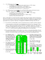
1
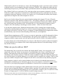
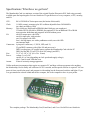
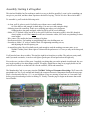
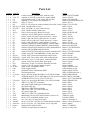
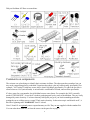
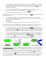
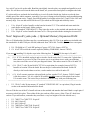
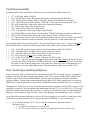
The 1802
Membership Card
For me and you and the 1802
TMSI c/o Lee Hart
814 8th Ave N
Sartell MN 56377 (USA)
[email protected]
http://www.sunrise-ev.com/membershipcard.htm
Rev. H2 -- last revised: 11/14/2015
1
What the heck is this? It's an adventure, by cracky! The "Membership Card" is your ticket to the weird and
wonderful world of microcomputing. Our guide will be the COSMAC 1802, perhaps the oddest and most
entertaining microprocessor yet invented. I hope you'll find this manual to be equally odd and entertaining.
The COSMAC 1802 was created in the 1970's at the dawn of the microcomputer revolution, by Joseph
Weisbecker of RCA Corporation. It used their new CMOS fabrication process, which had very low power
consumption, high noise immunity, and was very simple to use. It was intended for military and aerospace;
applications too tough for other microcomputers to survive.
But Joe was a hacker at heart. He wrote a series of articles starting in the August 1976 issue of Popular
Electronics magazine called "Build the COSMAC ELF". It described a simple low-cost computer, using the
1802 microprocessor. At the time, microcomputer systems cost hundreds to thousands of dollars. (Hmm...
they still do today!) But Weisbecker's ELF cost about $80! Yet, it was an honest-to-goodness real live
computer, able to do anything its much bigger cousins could do -- albeit a bit slower and cruder.
It was the ideal computer trainer. Hobbyists built thousands of ELFs, learning about computer design,
construction, and programming in the process. A dozen companies began producing versions of the ELF,
also selling for low prices. It was the "Legos" of computers; a simple building-block computer that could be
assembled many ways to become almost anything, limited only by your imagination.
I learned about computing on my ELF. It set me on a career in engineering, as it did for thousands of others.
1802's were designed into all sorts of amazing things; video games, music synthesizers, Chrysler engine
computers, military weapon systems, and even spacecraft such as NASA's Galileo. Eat stardust, x86 PCs!
So return with me now to those thrilling days of yesteryear, when the heroic pioneers of the microcomputer
revolution built their own computers from scratch, and programmed them to do incredible things, all for a
tiny amount of money!
What can you do with an 1802?
The Membership Card is much like the Arduino and Parallax BASIC Stamp. You can program it to do
simple tasks, and be the "brains" of your projects. It can blink lights, drive relays or small motors, run
displays, make annoying sounds with a speaker, read switches or sensors to measure things, perform
calculations, make decisions, and more. Unlike the Arduino and BASIC Stamp, the 1802 is far simpler and
uses much less power. Its machine language is very simple, and free assemblers are available. There are also
open source BASIC interpreters and C compilers for the 1802 to write and run really ambitious programs.
Once a program is loaded, it can be retained without power for hours by the onboard supercapacitor, or
indefinitely by maintaining power. Remember, this is a low power computer; it will run for a year on three
AA cells! Or, you can put your program in an EPROM so it won't be lost even without power.
The Front Panel can be unplugged, and the Membership Card used by itself. The Front Panel isn't needed
until you want to change the program, or debug or observe operation. For stand-alone use, connect power,
ground, and your desired inputs and outputs to J1 (the 30-pin header). Jumper J1 pins 13-14 (RUN to VDD)
to turn it on. Jumper pins 10-11 (/WE to /MWR) to enable writing to memory.
-Inspiration for this manual came from Jeff Duntemann's "Captain Cosmo's Whizbang" (c) 1980. The cover was inspired by its
cover cartoon by Chris Cloutier, and the one on the back cover by Bill Higgins.
2
Specifications: What have we got here?
The Membership Card is a miniature version of the original Popular Electronics ELF, built using currently
available parts and repackaged to fit in an Altoids tin. It's got the basics of every computer; a CPU, memory,
and I/O.
CPU:
Clock:
RCA CDP1802ACE microprocessor (the brains of this outfit)
1.8 MHz ceramic resonator, plus RC oscillator adjustable from 20-2000 KHz
(no, that's not MHz or GHz)
Memory:
2k to 64k bytes, RAM and/or EPROM (that's kilobytes, not megabytes)
U2 holds 2k-32k of RAM or EPROM, plus optional U8 for an additional 32k of RAM
supercapacitor holds data and programs in RAM without power
I/O:
one 8-bit output port, with LEDs
one 8-bit input port, with switches
one 1-bit output, with LED
four 1-bit flag inputs, one with a pushbutton switch, one with LED
one interrupt input
Connectors: 4-pin power connector (+V, RUN, LED, and -V)
25-pin DB25 connector with all the I/O and power on it
DB25 can plug into a PC parallel port to operate the Membership Card with the PC
DB25 also has RS-232 and TTL serial I/O (using Q and EF3)
Size:
3-1/2" x 2-1/8" x 3/4" (89 x 54 x 19 mm)
Power:
voltage: 3v to 5v DC
current: 0.1 to 2ma (depending on clock speed and supply voltage)
plus 1-3ma for each LED that is on
Aroma:
a hint of curiously strong peppermint
Unlike modern microcomputers that require an expensive PC and huge software programs to do anything,
the Membership Card is totally self-sufficient. No PC is needed, and no special software is required. You can
power it from a small solar panel, and program it with nothing but the front panel switches and lights. If you
ever get stranded on a desert island and need to compute, this is the computer to have in your pocket.
The complete package: The Membership Card, Front Panel, and Cover Card all fit in an Altoids tin.
3
Assembly: Getting it all together
This ain't no Heathkit, but I'm working to make it as easy to build as possible. I want it to be something you
can give to your kids, and have them experience the thrill of saying, "I did it! It's alive! Bwoo ha ha hah..."
To assemble it, you'll need the following tools:
- A clean, well-lit, place to work. Preferably one without cats or small children.
Or if the kids are old enough, let them help. (Cats are never old enough to help.)
- Soldering iron with a small tip. Don't use a soldering gun unless you're desperate.
Soldering these tiny parts and pads with a big fat tip will be a real challenge.
- Solder. 63/37 tin/lead is best, but 60/40 is also good. Lead-free electronics solder is also OK, though it
doesn't solder as well. But it must be rosin core electronics solder; NOT acid core plumbing or sheet
metal solder!
- Wire cutters. The smaller the better. Nothing is big here.
- Needle-nosed pliers. For bending or straightening lead wires, holding nuts, etc.
- Screwdriver with a 1/8" wide or smaller blade. For tightening mounting screws,
and adjusting the clock frequency pot.
- A magnifying glass. My old eyeballs aren't good enough to read the markings on some parts, or see
whether a solder joint is done right or is shorted to the pad next to it. Your eyes may not be that good,
either.
You'll need to know how to solder. This isn't the right kit to learn how to solder. The pads are pretty small,
and if you make a mistake, it can be a real fight to get the part off and put back on the right way.
First, make sure you have all the parts. I supplied everything that goes on the printed circuit boards, but you
may need to gather a few other things yourself. I'll supply Altoids tins as long as my supply holds out, but
you will have to drill or cut the holes in it for the switches, LEDs and connectors.
The Membership Card is your entry into the COSMAC College of Computer Knowledge. We'll start with
an aptitude test. See if you can find and identify the common electronic components listed on the next page.
Place a check mark in the box ( X ) as you find them. If any are missing, let me know so I can send it out
before you get bored and go back to watching TV. Ready? Turn the page to begin an adventure that could
last a lifetime...
Membership Card
Front Panel Card
4
Parts List
Quantity
( ) 1
( ) 4
( ) 1
( ) 1
( ) 8
( ) 1
( ) 4
( ) 2
( ) 1
( ) 3
( ) 1
( ) 1
( ) 1
( ) 1
( ) 1
( ) 1
( ) 1
( ) 1
( ) 1
( ) 1
( ) 1
( ) 2
( ) 4
( ) 3
( ) 1
( ) 1
( ) 1
( ) 11
( ) 3
( ) 1
( ) 1
( ) 1
( ) 1
Identifier
C1
C2-4, C7
C5
C8
D0-D7
D8
D9,10,13,14
D11, D15
D12
J1a,b,c
J2
P1
P2
P3
P4
Q1
Q2
Q3
Q4
Q5
R1
R3, R6
R4, R8-10
R5,R12,R13
R7
R11
R14
S0-S10
nuts
S11
U1
U1 socket
U2
(
(
(
(
(
(
(
(
(
(
(
(
(
(
(
U2 socket
U3
U4
U5
U6
U7
U9
U10
PCB
screw
spacer
standoff
jackscrew
jumper
case
)
)
)
)
)
)
)
)
)
)
)
)
)
)
)
1
1
1
1
1
1
1
1
1
2
2
2
2
4
1
Description
Source
ceramic resonator, 1.8 MHz (blue, marked 1.80Y)
Mouser 520-ZTT180MG
capacitor, 0.1uF X7R ceramic (blue, marked 104M)
Jameco 1570161
supercapacitor, 0.10F, 5.5vdc (black disk, 0.4" dia.)
Digikey 283-2818-ND
capacitor, 4.7uF ceramic (blue, marked 475)
Mouser 810-FK14X7R1E475K
LED, T1-3/4, red
Jameco 253753
LED, T1-3/4, red/green, common cathode (clear with 3 leads) Digikey 754-1232-ND
diode, 1N4148 (clear red case)
Jameco 36038
diode, 1N5231B 5.1v zener (clear red case)
Jameco 179047
diode, 1N5818 Schottky (black case)
Jameco 177957
socket, 10-pin top entry, Molex 22-18-2101
Digikey WM3241-ND
connector, 25-pin, DB25 female, vertical PC mount
Jameco 15165
header, 30-pin, with 0.025" square pins on 0.1" centers
Jameco 103342
header, 5-pin, with 0.025" square pins on 0.1" centers
Jameco 2076789
header, 4x2 pin, with 0.025" square pins on 0.1" centers
Jameco 109517
header, 4-pin, with 0.025" square pins on 0.1" centers
Jameco 117560
transistor, 5LN01SP N-channel MOSFET (marked YB4F)
Mouser 863-5LN01SP
transistor, 5LP01SP P-channel MOSFET (marked XB5A)
Mouser 863-5LP01SP
transistor, FJN4303 PNP with base resistors (marked R4303) Mouser 512-FJN4303RTA
transistor, 2N3904 NPN (marked 2N3904)
Jameco 38359
transistor, FJN3307 NPN with base resistors (marked R3307) Mouser 512-FJN3303RTA
trimpot, 1meg, BI Tech 64WR1MEG (3 leads, gray cube)
Jameco 2194902
resistor, 100k 1/4w (brown-black-black-orange-violet)
Jameco 691340
resistor, 499k 1/4w (yellow-white-white-orange-brown)
Jameco 691500 (470k)
SIP resistor, 8-pin, 7 x 100k (black, marked L81S104)
Mouser 858-L081S104LF
resistor, 1meg 1/4w (brown-black-green-gold)
Jameco 691585
SIP resistor, 10-pin, 9 x 1k (black, marked L101S102)
Jameco 97877
resistor, 3.3k 1/4w (orange-orange-red-gold)
Jameco 690988
toggle switch, subminiature SPDT
Digikey CKN1091-ND
for the toggle switches
comes with the switch
pushbutton switch, subminiature SPDT
Digikey CKN1740-ND
1802 microprocessor
eBay, or TMSI (that's me :-)
40-pin, ultra-low-height, Mill-Max 115-43-640-41-003000
Digikey ED90220-ND
32k RAM supplied. Use 2k-32k RAM (6116, 6264, 62256 etc) Jameco 42850 (32k RAM)
or EPROM (2716-27256 or 27C16-27C256 etc.)
Jameco 39731 (32k EPROM)
28-pin, very-low-height, Mill-Max 115-43-628-41-001000
Digikey ED90205-ND
74HC373 or 74HCT373 octal latch
Jameco 45831
4093 quad 2-input NAND gate, Schmitt trigger
Jameco 13400
4013 dual D flip-flop
Jameco 893443
74HC244 or 74HCT244 octal buffer
Jameco 45655
74HC374 or 74HCT374 octal D flip-flop
Jameco 45858
4071 quad 2-input OR
Jameco 13274
74HC157 or 74HCT157 quad data selector
Jameco 272170
Membership Card (rev.H2) and Front Panel Card (rev.H)
TMSI (me again)
#4-40 x 3/16" round head machine screw
Fastenal 1128626
#4 x 3/16" dia, 1/8" long plastic spacer
Mouser 749-9908-125
#4-40 x 3/16" dia, 5/16" long, hex female threaded standoff
Mouser 728-FC2054-440-A
#4-40 x 3/16" dia, .187" long female, 0.515" long male
Jameco 108987
jumpers for P2 and P3 headers
Mouser 737-MSB-G
"Altoids" (or equivalent) tin candy box
grocery or candy store
5
Did you find them all? Here are some hints:
Comments on components
The resistors use colored rings to identify their resistance in Ohms. The other parts have numbers, but you
may need a magnifying glass to read them! Capacitors have their value in Farads (usually picoFarads). For
example, "104" means 10 with four zeroes after it; that's 100,000pF (picoFarads). To add to the fun, this is
often written as 0.1uF (microFarads). A microFarad is a millionth of a Farad, and a million picoFarads.
ICs have room for a part number, but it's hidden between extra letters. For example, the 1802 is actually
marked "CDP1802ACE". Leave the ICs in their packaging until you're ready to install them. They are easily
damaged by static electricity. You know that tiny little spark you get if you touch something metal after
petting the cat or walking across a carpet? That's static electricity. In the microscopic world inside an IC, it
hits like a lightning strike. KABOOM! Your IC is dead.
Note: U8 and C6 are optional parts to expand memory to 64k. They are not supplied with the standard kit.
You can order them from me, or from the sources in the parts list on page 5.
6
Assembly
Assembly is a work in process. I'll just describe how I built mine. Please let me know if you find better ways
to do it! Check off the steps as you go ( X ), in case you get interrupted and have to come back to it later.
A couple things to keep in mind: To fit both boards in an Altoids tin, they must be built with the parts as low
as possible. Standard IC sockets are too high, so I've supplied special low-profile sockets. Likewise, the
plastic bodies of the square pin headers (P1 to P3) make them too tall, so the plastic bodies have to be
removed after soldering. You'll also need to trim the leads on the back of the boards very short as you go.
Ready? Let's get started!
Membership Card assembly
All parts go on the side of the board with the white silkscreened lettering (the top or "component" side). All
soldering is done on the other side (the back or "solder" side). The only exceptions are for connectors (and
I'll remind you when we get to them).
First, we'll install the lowest parts (the resistors):
(
)
R3: 100k ohm resistor (gray body, with brown-black-black-orange-violet color bands). Bend the
wire leads, and place it on the board at the location marked "R3". Bend the leads outward slightly to
hold it in place. Turn the board over, solder each lead, and cut off the excess as short as possible.
Install the rest of the parts the same way.
(
(
(
)
)
)
(
)
R4: 499k (brown body, with yellow-white-white-orange-brown bands).
R6: 100k (gray body, with brown-black-black-orange-violet bands).
R7: 1 meg (tan body, with brown-black-green-gold bands). Be sure to put the leads in the outer
holes, at the ends of the rectangle; not in the middle hole.
R2 is easy to install -- there isn't one!
Capacitors have two leads, but are installed pretty much the same. If the leads are bent, straighten them with
your needle-nosed pliers to fit the board. Then repeat the above steps to install each one.
(
(
(
(
)
)
)
)
C2: 0.1uF (blue, marked "104M").
C3: 0.1uF (blue, marked "104M").
C4: 0.1uF (blue, marked "104M").
C5: 0.10F (a black disk, marked "0.10F"). It has two flat leads, one with a "-" sign next to it. This
lead goes in the hole near the "-" and "C5" markings, closest to the corner of the board.
These next parts are a little bigger, with more leads:
(
)
(
)
R5: 8-pin SIP (Single Inline Package) with seven 100k resistors in it (black, marked "L81S104").
Put it at "R5" with pin 1 (the end with the white line) next to C4.
C1: 1.8 MHz ceramic resonator (blue body with 3 pins, marked "1.80Y").
7
(
)
Q1: 5LN01SP N-channel MOSFET transistor (black, with 3 leads, marked "YB4F"). Tiny, isn't it!
Insert it on the board at location "Q1", with the larger flat side marked YB4F facing up, toward "R1".
Put the center lead in the bottom hole, and the other two leads in the top holes. Push it down so it is
less than 1/4" (6mm) high.
(
)
Q2: 5LP01SP P-channel MOSFET transistor (black, with 3 leads, marked "XB5A"). Insert it at
location "Q2", with the larger flat side marked XB5A facing down, toward "C6".
(
)
R1: 1 megohm trimpot (a gray cube with 3 leads, marked "WR1MEG").
Diodes are polarity sensitive, and have a colored a band around one end. Be sure the banded end matches the
band shown on the board.
(
)
(
(
(
)
)
)
D9: 1N4148 (a reddish glass tube, with a wire at each end, and "1N4148" printed on it in tiny
letters). Bend the leads, and place it on the board at "D9" with the banded end as shown on the board.
Solder each lead, and cut off the excess.
D10: 1N4148.
D14: 1N4148.
D11: 1N5231B (reddish glass, marked "1N5231B"). It has tape on its leads, marked "D11".
Now for the pin headers: They get soldered on top, which is easier without the ICs in the way. Hint: Cover
the nearby IC holes with a piece of masking tape so you don't accidentally plug them with solder.
(
)
P1: 30-pin header. Insert the pins so the plastic body is against the bottom of the board (see drawing
below). Solder the pins on the top side. Don't use too much solder. Pry off the plastic body, and cut
the pins on the bottom as short as possible. Hint: To remove excess solder from the top, temporarily
push the plastic onto the top of the pins to hold them in place, and re-solder the pins from the bottom.
(
)
P2: 5-pin header. Install P2 the same as P1. Measure the height of the pins on top. If more than 1/4"
(6.3mm) high, tap them down into the plastic body. They must not be higher, or they will short to the
Front Panel. Solder on top, and cut the plastic body and pins on the bottom as short as possible.
(
)
P3: 6-pin header. Install it the same as P1 and P2. I supplied an 8-pin part. Remove 2 pins so it fits
on the board. Be sure the pins are no more than 1/4" (6.3mm) above the board.
Insert from bottom
check height
solder from top
cut off pin and body under board
ICs and static electricity: (Old pros and young fools can skip this paragraph.) ICs are easy to damage with
static electricity! Keep them in their protective packaging until needed. When you remove an IC, keep it in
your hand until it is on the board. Pick up the board or tool with your other hand. Do not have the IC be the
first thing to touch the tool or board. That way, any static electricity discharges into you, and not the IC.
ICs are polarity sensitive; they must be installed with the pin 1 end matching the marking on the board. The
pin 1 end may be marked in a number of ways; with a dot, notch, or line, etc. When the printing on the IC is
right side up and facing you, pin 1 is in the lower left corner. See the illustration on page 6 to find pin 1.
8
Lay each IC on its side on the table. Bend the pins slightly inward so they are straight and parallel to each
other. If it still does not fit into the holes on the board, use your needle-nosed pliers to straighten the leads.
IC sockets add cost, and make the board taller so it won't fit in the Altoids tin. Sockets are also the least
reliable part of the whole computer, especially if you use el-cheapo sockets! But they make troubleshooting
and chip replacement easier. I supply special high-quality low-height sockets for U1 and U2 (the 1802 and
memory chip). You can add sockets for the rest if you watch out for height and reliability issues.
(
)
(
(
)
)
U1a: 40-pin IC socket. Install it on the board at location "U1". The notched end must match the
notch shown on the board. Solder each pin.
U1: 1802 (marked "CDP1802ACE"). Plug it into the socket, so the notched end matches the board.
U2a: 28-pin IC socket. Install it the same as U1a. The open end with the missing bar is toward U1.
New! Improved! (yada yada...) Optional Memory Expansion RAM
The rev.G Membership Card has room for a second memory chip, U8. This is an option, not included with
the standard kit. It adds 32k bytes of RAM, addressed from 32k to 64k. To add it, you need two extra parts:
1. U8: 32k RAM in 0.3" wide DIP package (Cypress CY7C199; Jameco 242376).
2. C6: 0.1uF X7R axial lead ceramic capacitor (Mallory P20R104K5; Jameco 536542).
If you are not installing U8, skip the steps in the following box. To install U8, do steps A, B, and C:
----------------------------------------------------------------------------------------------------------------------------| A. ( ) U2: If U2 is installed, unplug it and set it aside. On the socket for U2, remove the 3 plastic bars
|
that connect its two rows of pins. The easiest way is to melt them in two with your soldering
|
iron, then cut off the excess with your diagonal cutters. This makes room for U8 to fit under U2.
|
| B. ( ) U8: 32k 0.3" wide 28-pin RAM (CY7C199 or equivalent; for example, Jameco 242376).
|
Install it at location U8 on the board. Be sure the pin 1 end matches the board. Solder U8
|
directly to the board without a socket; a socket makes it too tall to fit under U2.
|
| C. ( ) C6: 0.1uF ceramic capacitor with axial leads (yellow, marked "104"; Jameco 536542). Install
|
it like the resistors. Yes, it's a tight fit! If needed, carefully remove a little plastic from socket
|
U2a to make room. The easiest way to do this is to melt it away with your soldering iron.
----------------------------------------------------------------------------------------------------------------------------(
)
|
|
|
|
|
|
|
|
|
|
|
U2: 32k 0.6" wide 28-pin memory IC (marked "CXK58256P-10L" or equivalent). Plug it into the
socket so the notched end matches the board.
Now we'll do the rest of the ICs. Install each one so the notched end matches the board. Bend a couple pins if
necessary to hold it in place. Then solder all the pins, and cut off the excess. (Note: These ICs don't have
sockets. If you add sockets, remember they must have a very low height to fit in the Altoids case.)
(
(
(
(
(
)
)
)
)
)
U3:
U4:
U5:
U6:
U7:
74HC373 or 74HCT373 20-pin IC.
4093 14-pin IC.
4013 14-pin IC.
74HC244 or 74HCT244 20-pin IC.
74HC374 or 74HCT374 20-pin IC.
9
Front Panel assembly
Install these parts on the Front Panel Card the same way you did on the Membership Card:
(
(
(
(
(
(
(
(
(
(
(
)
)
)
)
)
)
)
)
)
)
)
C7: 0.1uF (blue, marked "104M").
D12: 1N5818 (black body). Be sure the end with the white band matches the board.
D13: 1N4148 (clear red body, marked "1N4148"). Be sure the band matches the board.
D15: 1N5231B (clear red body, marked "1N5231B"). It has tape on its leads, marked "D15".
R8: 499k (brown body, with yellow-white-white-orange-brown bands).
R9: 499k (yellow-white-white-orange-brown).
R10: 499k (yellow-white-white-orange-brown.
R14: 3.3k (tan body, with orange-orange-red-gold bands).
Q4: 2N3904 NPN transistor (black, 3 leads, marked "2N3904"). Position it as shown on the board.
Q5: FJN3307 NPN transistor (black with 3 leads, marked "R3307"). Install it like Q4.
P4: 4-pin header. This time, you can keep the black plastic body on it. Or if you prefer, leave P4 off,
and solder 4 small wires to the board instead, with any connector you like on the other end.
Next, install the SIP resistor networks and ICs. The end with the dot or line is "pin 1". It goes on the top in
the illustration below, to match the silkscreening on the board. Solder each lead, and cut off the excess.
(
(
(
(
(
(
)
)
)
)
)
)
R11: 10-pin SIP resistor network with nine 1K resistors (black, marked "L101S102").
R12: 8-pin SIP with seven 100K resistors (black, marked "L81S104").
R13: 8-pin SIP with seven 100K resistors (black, marked "L81S104").
U9: 4071 14-pin IC. Be sure pin 1 is at the correct end!
U10: 74HC157 or 74HCT157 16-pin IC. (That goes for U10 as well.)
J1a, J1b, J1c: Three 10-pin parts are supplied. Mount them on the BOTTOM of the board. The pins
go in the row of holes toward the CENTER of the board, with the connector's "cat ears" also toward
the center. Do not solder the empty holes close to the edge. Hint: Put a piece of masking tape over
these holes so you don't solder them closed. Solder the connector's pins, and cut off the "ears".
New! Serial Input and Output Options
Serial I/O uses the 1802's Q output and /EF3 input pins (note that /EF3 is inverted; Q is not). A program is
needed to "bit bang" the data in and out. For example, RCA's UT4 monitor, TMSI's IDIOT monitor, Tiny
BASIC, or Spare Time Gizmo's Elf2K EPROM. You can toggle the program in with the Front Panel
switches (tedious). Or download it with the parallel port (requires a PC with a parallel port). Or, install an
EPROM at U2 with the program in it (you'll need the EPROM, and the optional RAM at U8 -- see page 9).
Hardware-wise, serial I/O is on J2, the 25-pin D-connector on the Front Panel. Output TXD is on pin 15, and
input RXD is on pin 20. You can assemble the Membership Card for TTL (0-5v) or RS-232 (+/-12v) levels,
and either normal or inverted data. But you'll have to look up, or experiment to figure out what method the
thing you want to connect is using. See http://www.retrotechnology.com/memship/mem_rom_serial.html.
Each of the following three steps has two choices. If you're not going to use serial I/O, or don't know what
serial format you need, build it for TTL output levels, and for NORMAL (i.e. not inverted) data.
1. (
) C8: 4.7uF (blue, marked "475"). Yes, it really is 47 times more capacitance than C7!
Amazing, isn't it?
( ) For RS-232 serial levels (+v/-v), install C8.
( ) For TTL serial levels (0v-5v), short C8, or install a piece of wire in place of C8.
10
2. (
) P6: RXD jumpers for serial input:
( ) For NORMAL non-inverted data (where the idle state is a LOW voltage),
install jumper wires at P6 between 1-2, and between 3-4.
( ) For INVERTED data (where the idle state is a HIGH voltage),
install jumper wires at P6 between 2-3, and between 4-5.
3. (
) Q3: TXD transistor for serial output: Q3 is an FJN4307 PNP transistor with internal resistors
(black with 3 leads, marked "R4303"). It can be installed in two positions:
( ) For NORMAL non-inverted data (where the idle state is a LOW voltage),
install Q3 in the position marked "Q3N".
( ) For INVERTED data (where the idle state is a HIGH voltage),
install Q3 in the position marked "Q3I".
D8 is a 2-color LED. It is red when the 1802's Q output is high, and green when the 1802's EF3 input pin is
high. Since Q and EF3 are used for serial I/O, this LED is off when idle, and blinks red or green when data is
sent or received. If nothing is connected to the serial input, D8 is green if configured for NORMAL serial
input (think of it as a "power on" indicator). If configured for INVERTED serial input, D8 will be off.
( ) A. If you don't have a Cover Card, use the bare Front Panel board as a template to drill the Altoids tin
(or your own plastic or metal panel). I use the bottom of the Altoids tin as my "front panel". Drill
small 1/32" holes for the switches, LEDs, D-connector J2, and power connector P4. Then remove the
PC board, and enlarge the holes to the final size. Use a "step" drill bit, which won't tear the thin
metal. This is a long drill bit with a single cutting edge and steps in it to drill a dozen or so sizes from
1/8" to 1/2". Cut the D-connector opening with a nibbling tool or a lot of hand filing.
B. The optional Cover Card is available at http://www.sunrise-ev.com/membershipcard.htm. It has all
the labels and holes made for you (see photo on page 3). Just cut a big hole in the Altoids tin, and use
the card to cover the hole. Solder, screw, or glue it in place when done assembling the boards.
11
(
)
Wiggle the parts and boards so the LEDs and switches fit neatly into your Cover Card or front panel.
Work the board as close as you can. Careful! The switches can break if the holes in your front panel
don't match well enough. Hint: Use a 3/16" wide strip of cardboard to hold the LEDs at the same
height. Now solder the parts to the board, with the Cover Card holding everything in position.
(
)
Remove the mounting hardware from D-connector J2. Be sure you can easily remove, and re-install
the Cover Card. You may have to re-heat or reposition some parts, or enlarge some holes in your
front panel to make it fit easily. This may seem tedious, but it makes sure that all the parts are
soldered in the right places so they won't get forced or broken! :-)
Final Assembly -- Jumpers and Options
Next, install jumpers on the Membership Card to configure it for the type of memory chips at U2 and U8.
(
)
P2 and P3: Look at the type of memory chip installed at U2. Ignore the letters at the beginning and
end of the part number, and focus on the 3-digit number in the center. For example, if it is marked
"CXK58256P-10L" -- then it's a generic 256k bit (32k byte) RAM -- the standard chip I supply.
(
)
Find TABLE 1 in the bottom left corner of the schematic on page 20. Look up your chip number to
see what jumpers to install. For a 32k byte RAM (62256 etc.), install jumpers at P2 between pins 1-2
and 4-5, and at P3 between pins 1-3 and 2-4.
(
)
If U8 is installed, look for the pads between Q1 and Q2, labelled U2, U8, HI, and LO. Jumpers at
these pads control the addressing of U2 and U8. There are two options:
1. U2 to LO (0-32k)
U8 to HI (32-64k)
Standard; jumpers are etched onto the board for this.
a. RAM at U2 (the classic all-RAM "ELF" configuration): Load programs with the Front Panel.
b. Or, install a 2k to 32k EPROM at U2, and RAM at U8: Automatically runs programs in the
EPROM. For stand-alone controllers, since no Front Panel or manual program loading is needed.
c. Or, install RAMs at both U2 and U8. Now you have a 64k all-RAM system.
2. U2 to HI (32-64k)
U8 to LO (0-32k)
Optional; CUT the etched jumpers on the bottom of the
board (U2-LO, U8-HI), and jumper U2-HI and U8-LO.
a. Install RAM at U8. Load programs with the Front Panel. Socket U2 can be empty.
b. Or, put a 2k to 32k EPROM at U2, with programs that run in high memory (i.e. the Elf2K ROM).
Use the Front Panel to Load a LBR (address) instruction, then Run it to jump to the EPROM.
(
)
Jumper options A/B, Q0, Q1, Q2, Q3 are on the Front Panel card:
1. If you want to plug J2 into a PC parallel port, short A/B and leave O0, O1, O2, and O3 open. This
multiplexes the eight OUT4 bits into 4 bits, so a PC parallel port can control the Membership Card.
2. A/B: If you want to use J2 as a general-purpose I/O port with all eight OUT4 bits on pins of J2, leave
A/B open, and short O0, O1, O2, and O3.
(
)
Re-install the Cover Card with #4 mounting hardware as shown on page 11. Plug the Membership
Card and Front Panel cards together. Look between them to be sure that NOTHING touches between
the two boards except the 30-pin connector P1-J1, the top of trimpot R1, and the two hex standoffs. If
anything else touches, rework your solder joints or trim the leads on the back of the Front Panel so
there are no shorts.
12
(
)
Put nuts on a few of the switches (like the ones at each end). There isn't room for nuts on all of them.
They aren't really needed for such a small board. The hardware for J2 usually does the job.
(
)
Finally, screw the Membership Card to the threaded standoffs in J2 with two #4 screws.
(
)
The last page of this manual is a "cheat sheet" summary of operation. Cut out one vertical column,
and fold it to fit inside the Altoids box. It's a handy reminder, and also keeps the pins on the back of
the board from shorting to the metal case!
Power On!
Now it's time for the smoke test! We'll connect power, and try not to let any of the magic smoke out. (Old
timers will tell you that electronic devices don't work if the smoke gets out.)
The Membership Card takes very little power; 3v to 5v DC at 1ma, plus a few ma for each LED that is lit.
You can use three 1.5v batteries, a single lithium 3.6v cell, an old cellphone charger that outputs 5vdc, or
even the solar panel from a scrapped calculator for power. For example, a battery holder with three AA cells
in a second Altoids tin works nicely.
R1 sets the clock frequency (12 turns end-to-end). Fully clockwise is very slow, but very low power. Fully
counter-clockwise is maximum speed, which is OK at 5v but too fast with a 3v supply. C1 is a ceramic
resonator; at 5v it will "lock in" to 1.8 MHz with R1 adjusted fully counter-clockwise, then clockwise 3/4 to
1 turn.
Zener diode D11 is an "idiot" diode. If power is connected backwards, or is over 5.1 volts, or is AC instead
of DC, then D11 shorts it out to protect the rest of the board. At worst, D11 will get hot and fail shorted; but
it's cheap and easy to replace.
P4 is the power connector. It is a common male header with four 0.025" square pins on 0.100" centers,
located in the top left corner of the Front Panel board. There are many mating connectors. For example, the
4-pin cable used in PCs between the CDROM drive and sound card can be used. Other choices include:
A. Molex KK series: 22-01-3047 housing, and 08-55-0102 terminals (www.jameco.com 234819 and
234931). Common and easy to use, but not latched or keyed.
B. AMP latch series: 25403S-04 header, 25403H-04-R housing, 25403T terminals (www.jameco.com
152734, 152741, 181673). High quality, latched, keyed (if you use its header); hard to install terminals.
P4 pin
1
2
3
4
Name
+
RUN
LED
-
Function
VDD (or VCC), the power supply positive; +3 to +5 volts DC.
Controls the 1802's clock oscillator. Connect to pin 1 to Run; leave pin 2 open to Stop.
LED negative. Connect to pin 4 to enable the LEDs; leave pin 3 open to disable the LEDs.
VSS (or ground, common), the power supply negative.
Wire your power connector with positive (+) on P4 pins 1-2, and negative (-) on pins 3-4. To turn the
Membership Card "on", plug the power connector onto the board. This makes RUN high (clock runs), and
LED low (LEDs enabled). To turn it "off", unplug the connector; RUN goes low so the clock stops, and the
LEDs are disabled to minimize power.
13
On Rev.D and later, D-connector J2 pin 18 can be used for the + power input. It has a diode in series (D12),
so applying AC or reversing the power won't hurt anything. If you power your Membership Card it this way,
use a jumper plug at P4 to short pins 1-2 and 3-4. Unplugging or plugging it in becomes your on/off switch.
Supercapacitor C4 will hold programs and data for many hours. To hold them longer, leave power connected
to P4 pins 1 and 4. Use a DPST (double pole, single throw) switch to break the connections between pins 1-2
and 3-4. This switch provides "on" and "sleep" modes. "On" enables the clock and LEDs to work normally.
"Sleep" holds memory and turns the LEDs off so current very low; a set of AA cells will maintain memory
for years. Note: If the Front Panel is connected, it over-rides "Sleep" mode unless you also set the CLEAR
switch and all data switches S0-S7 low.
Operation
OK; so you connected power (and nothing smoked). Let's see if it works! The Front Panel selects the 1802's
operating mode and shows its status. LED D8 shows the state of the 1802 "Q" register; it will be off or green
at power-up. Data LEDs D0-D7 show the last data loaded or output by the 1802 program; they will initially
be some random value. Data switches S0-S7 set the input data. S11 is the IN button; press it to load data.
S8 is the READ/WRITE switch; WRITE lets you read or write to memory. READ makes memory read-only.
S9 and S10 are the mode switches, CLEAR and LOAD. They select the four operating modes as follows:
S9
Mode CLEAR
LOAD down
CLEAR down
WAIT up
RUN
up
S10
LOAD
down
up
down
up
1802 Operation
Waits for the next memory read/write (next press of the IN button).
Reset the 1802 (sets registers Q, X, P, and R0 all to 0).
Stops the program running in memory, and waits right where it is.
Runs (or resumes running) the program in memory.
Here's an example of how these switches and lights work.
1. Set switches S11-S0 as shown. "1" means the switch is up. "0" means the switch is down. "X" means
push the IN button. "." means the switch position doesn't matter. I'll show the switch positions like this:
Switch numbers and positions on the board
S11 S10 S9 S8
S7 S6 S5 S4 S3 S2 S1 S0
. 1 0 .
. . . . . . . .
PROGRAM 1 -- BLINK Q FAST
2.
3.
4.
S11 S10 S9 S8
S7 S6 S5 S4 S3 S2 S1 S0
. 1 0 .
. 1 0 1
. 0 0 1
. . . . . . . .
. . . . . . . .
. . . . . . . .
X 0 0 1
0 1 1 1 1 0 1 1
\ 7 / \ B /
Mode Description
CLEAR Resets the 1802.
Let's load a simple program to blink the "Q" LED:
Mode
CLEAR
WRITE
LOAD
Description
Reset the 1802 (sets R0 to address 0000).
Set S8 up, so we can write to memory.
Set both S9 and S10 down.
a. Set S7-S0 to "0111 1011", then press the IN button.
This loads hex 7B (the SEQ or "Set Q" instruction) into
memory address 0000, displays it in the LEDs, then
advances R0 from address 0000 to 0001.
14
X 0 0 1
0 1 1 1 1 0 1 0
\ 7 / \ A /
X 0 0 1
0 0 1 1 0 0 0 0
\ 3 / \ 0 /
X 0 0 1
0 0 0 0 0 0 0 0
\ 0 / \ 0 /
b. Set S7-S0 to "0111 1010", then press IN. This loads
hex 7A (the REQ or "Reset Q" instruction) into 0001,
displays it, then advances R0 to 0002.
c. Set S7-S0 to "0011 0000", then press IN. This loads
hex 30 (BR or "Branch Unconditionally") into 0002,
displays it, then advances R0 to 0003.
d. Set S7-S0 to "0000 0000", then press IN. Loads hex 00
(tells "Branch Unconditionally" where to jump; in this
case, back to 0), displays it, then advances R0 to 0004.
Our program is loaded. Let's read it back to see if it is correct.
X 0 0 0
0 1 1 1 1 0 1 0
\ 7 / \ A /
Description
Reset the 1802 (sets R0 to address 0000).
Set S8 down, so we can read memory.
Set both S9 and S10 down.
Press the IN button. This reads memory address 0000,
displays its contents in the LEDs ("0111 1011" which is
hex 7B), then advances R0 from address 0000 to 0001.
b. Press IN again. Displays "0111 1010" = hex 7A from
address 0001, then advances R0 from 0001 to 0002.
X 0 0 0
0 0 1 1 0 0 0 0
\ 3 / \ 0 /
c. Press IN again. Displays "0011 0000" = hex 30 from
address 0002, then advances R0 to 0003.
X 0 0 0
0 0 0 0 0 0 0 0
\ 0 / \ 0 /
d. Press IN again. Displays "0000 0000" = hex 00 from
address 0003, then advances to 0004.
S11 S10 S9 S8
5.
6.
7.
.
.
.
X
1
1
0
0
0
0
0
0
.
0
0
0
S7 S6 S5 S4 S3 S2 S1 S0
.
.
.
0
\
.
.
.
1
.
.
.
1
7
.
.
.
1
/
.
.
.
1
\
.
.
.
0
.
.
.
1
B
.
.
.
1
/
Mode
CLEAR
READ
LOAD
a.
If our program is correct, now we can run it!
8.
9.
. 1 0 .
. 1 1 .
. . . . . . . .
. . . . . . . .
CLEAR Reset the 1802 (set R0 back to address 0000).
RUN
Both S9 and S10 up. The 1802 begins running the
program starting at address 0000.
This program is very simple; it tells the 1802 to turn the Q LED on (red), then off (green), and repeat forever.
But it's doing it so fast that the LED looks orange. To prove that it's really going on and off, connect a pair of
headphones or a small speaker between J2 pin 15 (Q) and pin 20 (ground); you'll hear an audio tone!
Adjusting R1 (the SPEED trimpot) changes the pitch.
Or, we can use the WAIT mode to temporarily stop the program.
10.
. 0 1 .
. . . . . . . .
WAIT
Stop right where you are! The 1802 "freezes" where it
is in the program. The Q bit may be caught set, or reset.
Flipping S10 up and down will RUN and WAIT the program, sometimes catching Q set (red), sometimes
reset (green). WAIT is handy for debugging; you can stop at any time, and check any point in the circuit with
a meter or logic probe to see what is going on, then continue execution.
15
Here is a bit longer program. It does the same thing (blinks Q), but much s-l-o-w-e-r. Use the same sequence
of switch flipping as above. Let's simplify the description so it's not so wordy. See if you can figure out how
to enter it. (Hint: There's a "cheat sheet" at the end of this manual).
PROGRAM 2 -- BLINK Q SLOW
address
(R0)
0000
0001
0002
0003
0004
0005
0006
0007
0008
0009
000A
000B
000C
machine code
Hex
Binary
F8 1111 1000
08 0000 1000
B2 1011 0010
22 0010 0010
92 1001 0010
3A 0011 1010
03 0000 0011
CD 1100 1101
7B 0111 1011
38 0011 1000
7A 0111 1010
30 0011 0000
00 0000 0000
Mnemonic
LDI
8
PHI R2
DEC R2
GHI R2
BNZ
3
LSQ
SEQ
SKP
REQ
BR
0
Blink the Q LED slowly.
Human readable comments
LoaD Immediately...
...8
Put it in the HI half of register 2
DECrement register 2
Get the HI half of register 2
Branch if it is Not Zero...
...to address 3 (loops 8 x 256 = 2048 times)
Long Skip over next 2 instructions if Q=1...
...if Q was 0, then SEt Q=1
...and SKIP next instruction
else Q was 1, so REset Q=0
BRanch unconditionally...
...to address 0 (to begin again)
The instructions from 0000 to 0002 set up a 16-bit counter in register 2, and set it to hex 08xx. Instructions
0003 to 0006 are a loop; so register 2 counts down until it gets to hex 00FF. The high byte is then 00 (and the
low byte is left at FF); so the BNZ instruction stops looping and the program continues at address 0007.
The LSQ instruction tests Q; if Q=1, it skips ahead 2 and resets Q to 0. If Q=0, it continues to set Q to 1. The
result is to "toggle" Q on/off with each pass. Finally, the Branch instruction at 000B jumps back to the
beginning to repeat the whole thing forever. You can control the speed by changing the value at 0001, or by
adjusting trimpot R1.
PROGRAM 3 -- READ SWITCHES AND DISPLAY VALUE IN LEDS
This program is a bit more complex. It reads the 8 data switches, and displays their settings on the 8 LEDs. It
tests the Membership Card's ability to read and write to the switches and lights. Run it with S8 up (write).
address
(R0)
0000
0001
0002
0003
0004
0005
0006
0007
0008
0009
machine code
Hex
Binary
E1 1110 0001
90 1001 0000
B1 1011 0001
F8 1111 1000
10 0001 0000
A1 1010 0001
6C 0110 1100
64 0110 0100
30 0011 0000
00 0000 0000
Mnemonic
SEX 1
GHI 0
PHI 1
LDI
10h
PLO 1
INP 4
OUT 4
BR
0
Comments
Set X register to 1 (OMG! 1802's have sex instructions)
Get HIgh byte of register 0 in D (sets D=0)
Put D in HIgh byte of register 1 (so R1=00xx)
Load D Immediately with...
...10 hex
Put D in the LOw half of R1 (so R1 is now 0010)
INPut port 4 (front panel switches) & write it to memory at (R1)
OUTput to port 4 (front panel LEDs) contents of memory at (R1)
BRanch unconditionally...
...to address 0000
16
More Programming
Toggling in programs with the Front Panel gets old fast, doesn't it? It's really just there for testing and
debugging. For bigger programs, you'll want to use either the Parallel or Serial port to download programs
from your PC.
If your PC has a parallel port, all you need is a standard DB-25 male-to-male cable. Download the program
at http://www.sunrise-ev.com/MembershipCard/ELF-LINK.BAS. Set Read/Write switch S8 to READ
(down), all other switches UP, and run the ELF-LINK program. This is a Microsoft QuickBASIC program
that can completely control the Membership Card; it can operate all the switches, monitor all the LEDs, load
and save programs, etc. Even if you don't like BASIC, the program is posted in plain ASCII so you can write
a version in your favorite programming language. Now, who will be the first to translate it into C?
If you don't have a parallel port, there are many other ways to automate control and program loading. See the
web page at http://www.sunrise-ev.com/membershipcard.htm#projects for some of the ways to do it.
The current Rev.G Membership Card has a new way. It adds an RS-232/TTL serial interface, and a second
memory chip socket. It holds an EPROM with software to talk to a PC's RS-232 port (or USB port with a
serial-to-USB adapter). So far, we know it works with the Elf2K EPROM from Spare Time Gizmos
(http://www.sparetimegizmos.com/Downloads/v88.hex). I'm exploring other options as well. I plan to offer
an expansion kit with a preprogrammed EPROM and the extra RAM for U8 (as soon as I get a round tuit).
In Case of Difficulty...
The usual problems are bad solder joints. Either a pin hasn't been soldered, or there is too much solder so it
shorts to another pin.
Next, look for something too tall on the Membership Card that is shorting to the back of the Front Panel.
Likely candidates are the pin headers P2 and P3.
Look for parts installed backwards (diodes or ICs or SIP resistors), or in the wrong place (like resistors).
If all this looks right, make sure you have +3v to +5v power to the board. The voltage on U4 pin 12 (RUN)
should be high to enable the oscillator. U4 pin 11 will be 1/2 the supply voltage if the oscillator is running.
Switch to RUN, and look for signals on the 1802 TPA, TPB, /MRD, and SC0 pins. Even if it is executing
nonsense (no program), these pins will still be pulsing high/low as the 1802 tries to read memory. Also check
to see that all the 1802 MA0-7 and BUS0-7 pins are going high and low (so none are open or shorted).
Check the voltage on 1802 /EF4 input. It should be high, and go low when you push the IN button. If it's the
opposite, you have the pushbutton in backwards. Here is how LOAD mode works:
- Press IN. The 1802 /EF4 pin and flip-flop U5B pin 11 go low.
- Release IN. /EF4 goes high. U5B sets, so its /Q output pin 12 goes low. This makes 1802 /DMA-IN go low.
- The 1802 does a DMA in cycle. It puts an address on MA0-7, and pulses /MWR low to write to memory.
- During a Write cycle, /MRD is high. N2.or.LOAD is also high as we are in LOAD mode, so U4C pin 10 is
low. This enables U6 to put the 8 DATA switches on BUS0-BUS7, where they get written into memory.
- 1802 SC1 is high during a DMA cycle; this resets U5B. The 1802 then does a read cycle (/MRD low) to
read the byte just written to memory. /MRD low lets U5A set when TPB goes high, to latch the byte in U7.
Still doesn't work? Email me for help at [email protected]. Failing that, send it to me and I'll fix it! :-)
17
Last Writes
I'm still working on this manual, to add better assembly directions, instructions for troubleshooting, and ways
to use your PC to load and save programs without all that flippin' switch flipping. I hope what I have so far
is enough to get you going. If not, please contact me with comments, corrections, questions, or ways to
improve it. My contact information is on the first page. Watch the websites listed below for the latest details!
Changes along the way:
July 2010: Rev.A board: Changed R8-R10 from 100k to 470k.
Aug 2010: Rev.B: Added Q1 and C6. Changed I/O port from 5/7 to 4/5/6/7 to match Elf. Added RUN to P4.
Nov 2010: Changed R4 and R8-10 from 470k to 499k, and C6 from 82pf to 100pf (for expediency; I ran out
of 470k and 82pf parts, and had lots of 499k and 100pf).
Jul 2011: Rev.C: Fixed silkscreen I/O port names; IN5/7 now INP4, OUT5/OUT7 now OUT4. (IN and OUT
ports still respond to any port number from 4-7). Added "Cover Card" for a more finished appearance.
Aug 2011: Corrected P2 jumper chart on schematic. For 6116, 2716, 2732; P2 was 2-3, changed to 3-4. For
2764; P2 was 3-4, changed to 2-3. For 27128 and 27256; P2 was 1-2 and 3-4, changed to 2-3 and 4-5.
Sept 2011: Added power supply info.
Jan 2012: Added photos of finished boards.
Mar 2012: Added "cheat sheet" summary page.
Apr 2012: R1 changed from 1meg to 500k (I ran out of 1meg pots).
June 2012: Rev.D board: R1 went back to 1meg. R2 changed to 5.6k (to raise maximum clock frequency).
Added D12 (so power is available on DB25 connector J2). Added R14 (to use J2 pin 1 for serial input).
Added jumpers A/B, O0, O1, O2, and O2 (to use J2 for general purpose I/O instead of PC parallel I/O).
Aug 2012: Ran out of parts; so changed C5 from 0.047F to 0.022F, and R2 and R14 from 5.6k to 6.8k.
Jan 2013: Rev.E: Made room for a bigger supercapacitor at C5 (now 0.10F or 0.22F).
May 2013: Rev.F: Changed C1 to ceramic resonator (more stable frequency). Removed R2 to make room.
Feb 2014: Rev.G: Added 32k RAM (U8; under U2); can have 32k RAM plus 32k EPROM! Add serial I/O
using Q and EF3 to D-connector (Q2, Q3, C8, D13, R15). Add 2-color LED at D8 (shows Q and EF3).
Mar 2015: Rev.H: Q1 changed from 2N7000 to FJN3301, and R5 from 100k to 10k for faster /A15 rise time.
Added D14 for power-on CLEAR even if front panel switches are set to RUN. Add P6 to Front Panel.
May 2015: Rev.H2: Replaced Q1 with Q1+Q2 to make a proper inverter for fastest /A15 rise time.
Links for more about the 1802 and ELF computers:
http://www.sunrise-ev.com/membershipcard.htm
This is my website, with ordering information, manual updates, schematics, cheat sheets, and more.
http://incolor.inebraska.com/bill_r/elf/html/elf-1-33.htm
This is the Aug 1976 Popular Electronics article that introduced the ELF to hobbyists. Most of it applies
directly to the Membership Card.
http://datasheets.chipdb.org/RCA/MPM-201B_CDP1802_Users_Manual_Nov77.pdf
An online copy of RCA's User Manual for the 1802. "Must read" reference material!
http://www.ittybittycomputers.com/IttyBitty/ShortCor.htm
"A Short Course in Programming" by Tom Pittman. An excellent introduction to programming the 1802.
http://www.cosmacelf.com
The COSMAC ELF "fan club", with lots of information on the many commercial and hobbyist variants.
http://www.retrotechnology.com/memship/memship.html
Herb Johnson's website on the Membership board. He built one of the first ones, and has done a great job
documenting it (many thanks, Herb)! There are loads of design notes, history, software examples, etc.
18
"Mugshots" of the Elf Membership Card 3-board Set
Cover Card (1:1 scale): Can use as a drilling template.
Front Panel Card (1:1 scale): Part location and placement guide.
Membership Card (1:1 scale): Part location and placement guide.
19
20
21
The Inside Story...
How the 1802 in an Elf
computer REALLY works!
22