1
Pololu Zumo Shield for Arduino User’s Guide
© 2001–2015 Pololu Corporation
Pololu Zumo Shield for Arduino
User’s Guide
View document on multiple pages. [https://www.pololu.com/docs/0J57]
View this document as a printable PDF: zumo_shield_for_arduino.pdf
[https://www.pololu.com/docs/pdf/0J57/
zumo_shield_for_arduino.pdf]
https://www.pololu.com/docs/0J57/all
Page 1 of 42
Pololu Zumo Shield for Arduino User’s Guide
1. Overview . . . . . . . . . . . . . . . . . . . . . . . . . . . . . . . . . . . .
1.a. Contacting Pololu . . . . . . . . . . . . . . . . . . . . . . . . . . . .
1.b. Included components . . . . . . . . . . . . . . . . . . . . . . . . . .
2. Assembly . . . . . . . . . . . . . . . . . . . . . . . . . . . . . . . . . . . .
2.a. What you will need . . . . . . . . . . . . . . . . . . . . . . . . . . .
2.b. Assembling the Zumo Shield and chassis . . . . . . . . . . . . . . .
2.c. Adding a Zumo reflectance sensor array (optional) . . . . . . . . . .
3. The Zumo Shield in detail . . . . . . . . . . . . . . . . . . . . . . . . . . .
3.a. Features and components . . . . . . . . . . . . . . . . . . . . . . . .
3.b. Front expansion . . . . . . . . . . . . . . . . . . . . . . . . . . . . .
3.c. Jumper settings . . . . . . . . . . . . . . . . . . . . . . . . . . . . .
3.d. Inertial sensors (accelerometer, magnetometer, and gyro) . . . . . . .
4. Schematic diagrams . . . . . . . . . . . . . . . . . . . . . . . . . . . . . .
5. Arduino pin assignment table . . . . . . . . . . . . . . . . . . . . . . . . .
6. Zumo Shield Arduino Libraries . . . . . . . . . . . . . . . . . . . . . . . .
7. Example projects . . . . . . . . . . . . . . . . . . . . . . . . . . . . . . . .
7.a. RC Zumo . . . . . . . . . . . . . . . . . . . . . . . . . . . . . . . .
7.b. Simple border-detecting sumo robot . . . . . . . . . . . . . . . . . .
7.c. Collision-detecting sumo robot . . . . . . . . . . . . . . . . . . . . .
7.d. Line follower . . . . . . . . . . . . . . . . . . . . . . . . . . . . . .
7.e. Maze solver . . . . . . . . . . . . . . . . . . . . . . . . . . . . . . .
7.f. Using the compass . . . . . . . . . . . . . . . . . . . . . . . . . . .
8. Controlling a servo . . . . . . . . . . . . . . . . . . . . . . . . . . . . . . .
8.a. Controlling a servo with an Arduino Uno . . . . . . . . . . . . . . .
8.b. Controlling a servo with an Arduino Leonardo or A-Star 32U4 Prime
© 2001–2015 Pololu Corporation
.
.
.
.
.
.
.
.
.
.
.
.
.
.
.
.
.
.
.
.
.
.
.
.
.
.
.
.
.
.
.
.
.
.
.
.
.
.
.
.
.
.
.
.
.
.
.
.
.
.
.
.
.
.
.
.
.
.
.
.
.
.
.
.
.
.
.
.
.
.
.
.
.
.
.
.
.
.
.
.
.
.
.
.
.
.
.
.
.
.
.
.
.
.
.
.
.
.
.
.
.
.
.
.
.
.
.
.
.
.
.
.
.
.
.
.
.
.
.
.
.
.
.
.
.
.
.
.
.
.
.
.
.
.
.
.
.
.
.
.
.
.
.
.
.
.
.
.
.
.
.
.
.
.
.
.
.
.
.
.
.
.
.
.
.
.
.
.
.
.
.
.
.
.
.
.
.
.
.
.
.
.
.
.
.
.
.
.
.
.
.
.
.
.
.
.
.
.
.
.
.
.
.
.
.
.
.
.
.
.
.
.
.
.
.
.
.
.
.
.
.
.
.
.
.
.
.
.
.
.
.
.
.
.
.
.
.
.
.
.
.
.
.
.
.
.
.
.
.
.
.
.
.
.
.
.
.
.
.
.
.
.
.
.
.
.
.
.
.
.
.
.
.
.
.
.
.
.
.
.
.
.
.
.
.
.
.
.
.
.
.
.
.
.
.
.
.
.
.
.
.
.
.
.
.
.
.
.
.
.
.
.
.
.
.
.
.
.
.
.
.
.
.
.
.
.
.
.
.
.
.
.
.
.
.
.
.
.
.
.
.
.
.
.
.
.
.
.
.
.
.
.
.
.
.
.
.
.
.
.
.
.
.
.
.
.
.
.
.
.
.
.
.
.
.
.
.
.
.
.
.
3
4
4
7
7
8
18
25
25
27
28
30
32
33
34
36
36
37
38
39
39
39
40
40
42
Page 2 of 42
Pololu Zumo Shield for Arduino User’s Guide
© 2001–2015 Pololu Corporation
1. Overview
The Zumo Shield provides a convenient interface between our Zumo chassis [https://www.pololu.com/product/
1418] and an A-Star 32U4 Prime [https://www.pololu.com/category/165/a-star-32u4-prime], Arduino Uno
[https://www.pololu.com/product/2191], or Arduino Leonardo [https://www.pololu.com/product/2192] (it is not compatible
with the Arduino Mega or Due, but it can be used with older Arduinos that have the same form factor as the
Uno, such as the Duemilanove). The shield mounts directly to the chassis, connecting to its battery terminals
and motors, and the Arduino plugs into the shield’s male header pins, face down. The shield provides all the
electronics necessary to power the motors and includes some additional fun components for making a more
interesting robot, such as a buzzer for making sounds and inertial sensors including an accelerometer and gyro.
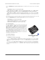
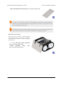
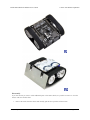
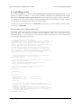
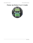
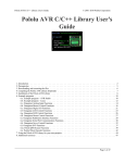
Zumo Shield for Arduino, v1.2, as it
ships (assembled with surface-mount
components only).
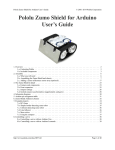
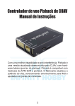
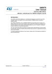
Assembled Zumo robot for Arduino
with an Arduino Uno (with original
white sprockets).
A Zumo chassis, Zumo Shield, and Arduino (or compatible board) can be combined to become a low-profile,
Arduino-controlled tracked robot that is less than 10 cm on each side (small enough to qualify for Mini-Sumo
competitions).
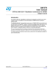
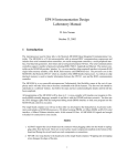
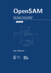
Zumo robot assembled with a Zumo
Shield and Arduino Uno, back view.
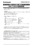
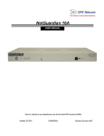
Main features of the Zumo Shield for
Arduino, v1.2.
The latest revision of the Zumo Shield is version 1.2. This version adds an L3GD20H
[https://www.pololu.com/product/2129] 3-axis gyroscope and upgrades the accelerometer and magnetometer chip to
1. Overview
Page 3 of 42
Pololu Zumo Shield for Arduino User’s Guide
© 2001–2015 Pololu Corporation
the newer LSM303D [https://www.pololu.com/product/2127]. It is available by itself, as part of a kit, or in a complete
robot:
• Zumo Shield, v1.2 [https://www.pololu.com/product/2508]
• Zumo robot kit for Arduino, v1.2 [https://www.pololu.com/product/2509] with a Zumo chassis
[https://www.pololu.com/product/1418] and a stainless steel Zumo blade [https://www.pololu.com/product/1410]
• Zumo robot for Arduino, v1.2 [https://www.pololu.com/product/2510], fully assembled with 75:1 HP
motors [https://www.pololu.com/product/2361] and a reflectance sensor array [https://www.pololu.com/product/1419]
installed.
The information in this user’s guide also applies to the original Zumo Shield, which did not have a gyro and
featured an LSM303DLHC [https://www.pololu.com/product/2124] accelerometer and magnetometer:
• Zumo Shield [https://www.pololu.com/product/2504]
• Zumo robot kit for Arduino [https://www.pololu.com/product/2505]
• Zumo robot for Arduino [https://www.pololu.com/product/2506]
1.a. Contacting Pololu
We would be delighted to hear from you about your experiences with
the Zumo Shield for Arduino [https://www.pololu.com/product/2508],
Zumo robot kit for Arduino [https://www.pololu.com/product/2509], or
Zumo robot for Arduino [https://www.pololu.com/product/2510]. If you
need technical support or have any feedback you would like to share,
you can contact us [https://www.pololu.com/contact] directly or post on our
forum [http://forum.pololu.com/viewforum.php?f=29]. Tell us what we did
well, what we could improve, what you would like to see in the future,
or anything else you would like to say!
1.b. Included components
The Zumo Shield is available:
• by itself [https://www.pololu.com/product/2508];
Fully assembled Zumo chassis
with assembled Zumo Shield
(v1.0).
• as part of a Zumo robot kit for Arduino [https://www.pololu.com/product/2509] that also includes a Zumo
chassis [https://www.pololu.com/product/1418] and a stainless steel Zumo blade [https://www.pololu.com/product/
1410]; or
• as a fully-assembled Zumo robot for Arduino [https://www.pololu.com/product/2510] with 75:1 HP motors
[https://www.pololu.com/product/2361] and a reflectance sensor array [https://www.pololu.com/product/1419]
installed.
1. Overview
Page 4 of 42
Pololu Zumo Shield for Arduino User’s Guide
© 2001–2015 Pololu Corporation
Zumo Shield
The shield itself comes with the following
components:
• right-angle slide switch
• two pushbuttons [https://www.pololu.com/product/
1400]
• buzzer
• 2-pin
battery-charging
header
[https://www.pololu.com/product/1012]
• three jumper wires (for soldering motors to the
shield)
• two 25-pin 0.1″ straight breakaway male headers [https://www.pololu.com/product/965]
• four blue shorting blocks [https://www.pololu.com/product/968]
• two 5/16″ #2-56 machine screws (to be used instead of the 1/4″ screws included with the chassis kit if
you attach a Zumo blade)
• 1/16″ black acrylic spacer plate (two pieces)
Zumo Robot Kit for Arduino
In addition to the shield and its included hardware, the Zumo robot kit for Arduino also includes these
components:
• Zumo
chassis
[https://www.pololu.com/product/1418],
kit
which
includes:
◦ Zumo chassis main body
◦ 1/16″ black acrylic mounting plate (not used
with the Zumo Shield)
◦ Two drive sprockets
◦ Two idler sprockets
◦ Two 22-tooth silicone tracks
◦ Two shoulder bolts with washers and M3
nuts
◦ Four 1/4″ #2-56 screws and nuts
◦ Battery terminals
1. Overview
Page 5 of 42
Pololu Zumo Shield for Arduino User’s Guide
© 2001–2015 Pololu Corporation
• Basic sumo blade for Zumo chassis [https://www.pololu.com/product/1410]
You will receive the black acrylic spacer and mounting plates with protective paper masking on
both sides. You can peel this masking off to expose the acrylic surface, or you can leave it on to
increase the thickness of the plates.
The shield and chassis kit include extra parts like jumper wires, screws, nuts, and washers, so do
not be concerned if you have some leftover hardware after assembling your Zumo.
Zumo Robot for Arduino
The Zumo robot for Arduino is a fully-assembled
robot platform built from the same components
found in the Zumo robot kit for Arduino, along with
these additions:
• Two 75:1 HP micro metal gearmotors
[https://www.pololu.com/product/2361]
• Zumo
reflectance
sensor
array
[https://www.pololu.com/product/1419]
1. Overview
Page 6 of 42
Pololu Zumo Shield for Arduino User’s Guide
© 2001–2015 Pololu Corporation
2. Assembly
If you have a Zumo robot kit for Arduino [https://www.pololu.com/product/2509] or a separate Zumo Shield
[https://www.pololu.com/product/2508] and chassis [https://www.pololu.com/product/1418], this section will guide you
through assembling them into a complete robot.
If you purchased an assembled Zumo robot for Arduino [https://www.pololu.com/product/2510], this assembly work
has been done for you, although you might want to configure your Zumo by adding or removing some jumper
connections [https://www.pololu.com/docs/0J57/3.c]. Otherwise, you can simply install four AA batteries and an
Arduino (or compatible controller) and skip to Section 3 to start learning how to use your Zumo!
2.a. What you will need
The Zumo Shield is designed to be mounted on a Zumo chassis kit [https://www.pololu.com/product/1418], which
is included (along with a Zumo blade [https://www.pololu.com/product/1410]) if you have a Zumo robot kit for
Arduino [https://www.pololu.com/product/2509]. In addition, you will require these items to construct a working
Arduino-controlled Zumo robot:
Additional required components
• Two micro metal gearmotors [https://www.pololu.com/category/60/micro-metal-gearmotors] (we recommend
100:1
[https://www.pololu.com/product/1101],
75:1
[https://www.pololu.com/product/2361],
or
50:1
[https://www.pololu.com/product/998] gear ratio versions with HP motors). The pre-assembled version of the
Zumo robot [https://www.pololu.com/product/2510] includes two 75:1 HP micro metal gearmotors.
• An Arduino or compatible board (we recommend an A-Star 32U4 Prime [https://www.pololu.com/category/
165/a-star-32u4-prime], Arduino Uno R3 [https://www.pololu.com/product/2191], or Arduino Leonardo
[https://www.pololu.com/product/2192])
• Four AA batteries (we recommend rechargeable AA NiMH cells [https://www.pololu.com/product/1003])
Please see the product description for the chassis kit [https://www.pololu.com/product/1418] for more information
and recommendations about selecting these components.
Additional optional components
• Zumo reflectance sensor array [https://www.pololu.com/product/1419]
• Basic sumo blade for the Zumo chassis [https://www.pololu.com/product/1410]
• Sensors
[https://www.pololu.com/category/7/sensors],
such
as
our
QTR
reflectance
sensors
[https://www.pololu.com/category/123/pololu-qtr-reflectance-sensors]
• Connectors and jumper wires
sensors and components
[https://www.pololu.com/category/19/connectors],
• Battery charger (such as the iMAX-B6AC
rechargeable batteries
for connecting additional
[https://www.pololu.com/product/2588]),
if you are using
Assembly tools
• Soldering iron and solder (we recommend one with adjustable temperature control)
• Wire cutter
• Small Phillips screwdriver
2. Assembly
Page 7 of 42
Pololu Zumo Shield for Arduino User’s Guide
© 2001–2015 Pololu Corporation
• 3 mm Allen wrench (hex key)
• long-nose pliers (for bending the Zumo blade mounting tabs)
2.b. Assembling the Zumo Shield and chassis
Please follow these instructions carefully to assemble your Zumo Shield and chassis properly. (These pictures
show the original Zumo Shield [https://www.pololu.com/product/2504], but the assembly process is the same for the
latest v1.2 version [https://www.pololu.com/product/2508].)
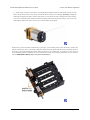
Through-hole parts
1. Solder
the
included
through-hole components to
the shield:
◦ power switch
◦ reset pushbutton
◦ user pushbutton
◦ buzzer
◦ charging
connector
(1×2-pin female header)
2. On the bottom of the
board, trim any leads longer
than 1/16″ (the thickness of the
spacer plate) so they do not
prevent the shield from sitting
flat on the spacer plate and
chassis.
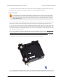
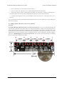
Arduino headers
3. Separate the 1×40-pin
breakaway male header into
the appropriate segments for
connecting your Arduino and
solder them to the shield.
These header segments should
be soldered to the sets of holes outlined with white rectangles on the top of the shield, with the pins facing
up.
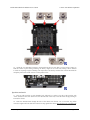
The A-Star 32U4 Primes and the newest Arduino boards, including the Uno R3 and the Leonardo, use one 1×10
header, two 1×8 headers, and one 1×6 header; older Arduino boards use two 1×8 headers and two 1×6 headers
(the two pairs of pins highlighted above in red should not be populated if you are using this board with an older
Arduino that does not support these additional pins). Please make sure you solder the appropriate headers for
your particular Arduino!
An easy way to line up the Arduino headers for soldering is to plug them into an Arduino, then place the shield
upside-down on top of them, as shown in the picture below. Be careful to insert the header pins into the correct
set of holes before you begin soldering. Note: if you use this alignment technique, make sure your soldering iron
2. Assembly
Page 8 of 42
Pololu Zumo Shield for Arduino User’s Guide
© 2001–2015 Pololu Corporation
temperature is not excessively hot and avoid holding the iron on a single pin for more than a few seconds as this
could melt the Arduino’s female headers.
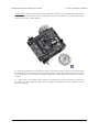
4. On the bottom of the board, trim the four Arduino header pins closest to the front of the board on each
side to prevent them from contacting the motor housings. If you think there is a chance these pins might
still touch the motor cases, you can put some electrical tape on the motors to act as insulation.
Jumpers and additional connections
5. Optional: If you want to enable the buzzer, enable the battery level input, or disable the compass,
now is a good time to add and/or cut jumper connections to configure the shield to your liking. This can
also be done later, though soldering to these pins is more difficult once the robot is assembled (especially
if you decide later you want to add header pins for use with shorting blocks; this would require a lot of
disassembly). The jumpers are explained in detail in Section 3.c. The buzzer and battery level jumpers can
be connected by soldering in a short piece of wire between the two holes, while the compass I²C connections
can be broken by cutting the trace on the top of the board between the holes. Note: there is not enough
clearance to use male headers on the battery level and compass I²C jumpers if you are using an Arduino
with a DIP (through-hole) microcontroller.
2. Assembly
Page 9 of 42
Pololu Zumo Shield for Arduino User’s Guide
© 2001–2015 Pololu Corporation
Instead of making a wire connection, you can solder a 1×3 male header to the buzzer jumper holes
to allow the use of a shorting block for connecting the buzzer. You can also use male headers
and shorting blocks for the battery level jumper and compass jumpers if you have an Arduino
Uno with an SMD (surface mount) microcontroller, Arduino Leonardo, or A-Star 32U4 Prime.
However, there is not enough clearance to use male headers on the battery level and compass I²C
jumpers if you are using an Arduino with a DIP (through-hole) microcontroller.
6. Optional: At this point, you might consider soldering additional components (such as sensors), or
headers or wires for connecting them, to the shield. If you do this, please check to make sure your part
placement does not interfere with the shield’s ability to mate with the Arduino or the chassis. In particular,
note that only components in the outermost three rows of the front expansion area can extend below the
board (the fourth front-expansion row can only be used for pins extending above the board), and if you add
any through-hole parts to the prototyping areas on the shield, you will need to drill corresponding holes in
the acrylic spacer plate for the leads to fit into.
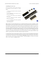
Motors
7. Cut two of the included jumper wires in half to form four segments, and trim off the ends that are
covered in adhesive (the adhesive could interfere with making a good electrical connection to the motor).
These wire segments will be used as motor leads.
2. Assembly
Page 10 of 42
Pololu Zumo Shield for Arduino User’s Guide
© 2001–2015 Pololu Corporation
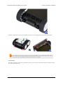
8. Solder a pair of leads to each motor. You might find it helpful to make a small bend at the tip of each
lead to hook into the hole in the motor lead tab to hold it in place for soldering. Warning: holding the
soldering iron against the motor lead for more than a few seconds can start to damage the motor brushes,
so try to be reasonably quick/efficient with this soldering; if the first attempt does not go well, remove the
soldering iron and let the motor cool for a few seconds before trying again.
Each motor’s positive terminal is indicated by a plus sign (+) in the black plastic end of the motor, visible at the
bottom of the picture above. The motors should be soldered into the shield with the positive terminal closest to
the front, so you should attach the leads to allow the motors to be oriented this way. (However, don’t worry if
you accidentally get the orientation of one or both motors wrong. You can later compensate for it in software
with our ZumoMotors library [https://www.pololu.com/docs/0J57/6].)
2. Assembly
Page 11 of 42
Pololu Zumo Shield for Arduino User’s Guide
© 2001–2015 Pololu Corporation
9. Place the motors into the channel in the front of the chassis, aligning the gearbox with the grooves in
the channel. The front plate of the gearbox should be even with the edge of the chassis.
Chassis and shield
To assemble the chassis with the Zumo Shield, you should use the two-piece acrylic spacer plate
that is included with the shield. You will not need the one-piece mounting plate that is included
with the Zumo chassis.
10. Place an M3 nut in each of the two side slots near the rear of the chassis. The slots are sized so that
nuts will not be able to rotate within them. (These nuts will be used to mount the idler sprockets later.)
11. If you want, peel the protective paper masking off both sides of the acrylic spacer plate pieces (the
spacer plates in our pictures show what they will look like with the masking peeled off). Alternatively, you
can leave the masking on for additional thickness. If you leave the masking on, it will be mostly concealed
when the robot is fully assembled.
12. Cover the chassis and motors with the spacer plate pieces and then the Zumo shield. The holes in the
spacer plate should line up with the through-holes in the shield resting on top of it, and the motor leads
should be aligned so they pass through the slots in the spacer as shown in the picture below. There is only
one correct orientation for these plates. (The plate consists of two separate pieces to make it possible to
disassemble the Zumo without having to desolder the motors or battery terminals.)
13. In each of the four mounting holes, insert a #2-56 machine screw through the shield, spacer plate, and
chassis, and tighten it against a nut under the chassis. It is usually easier to place the nut into the recess
2. Assembly
Page 12 of 42
Pololu Zumo Shield for Arduino User’s Guide
© 2001–2015 Pololu Corporation
first and hold it there with a finger or piece of tape while inserting the screw. Note that the kit includes two
different sizes of #2-56 machine screws: 1/4″and 5/16″. The two longer screws are intended for use in the
front holes (near the motors) if you are also mounting a sumo blade; otherwise, you can use the shorter 1/4″
screws for all four mounting holes.
If you are also adding a basic sumo blade, you can either mount it now or add it later after you are done soldering
the motors and battery contacts. (Note: If you intend to solder anything to the front expansion area of the shield,
such as a Zumo reflectance sensor array, you will have more room to work if you do the soldering before adding
the sumo blade.)
Note: There is a small chance the mounting tabs of the blade can cause shorts where it contacts the
shield if the PCB solder mask is not thick enough, so we recommend adding some electrical tape or
other insulating material between the blade and shield.
To install the blade, first bend its mounting tabs to the appropriate angle. Next, place them on top of the shield
so that the holes line up with the two front mounting holes and insert the two longer (5/16″) #2-56 machine
screws (included with the shield) through the blade, shield, spacer plate, and chassis. Be careful when adjusting
the angle of the sumo blade while it is mounted to the chassis, as this can crack the acrylic spacer plate if you
apply sudden or excessive force. We recommend you do not try bending the blade while it is mounted to the
chassis.
14. Solder each motor lead to the shield, then trim off the excess length of wire.
2. Assembly
Page 13 of 42
Pololu Zumo Shield for Arduino User’s Guide
© 2001–2015 Pololu Corporation
Battery contacts
15. Turn the chassis over and install the battery terminal contacts as shown in the picture below. The three
double-contact pieces should be firmly pressed into place until they are flush with the interior surface of the
battery compartment. The two individual contacts should be inserted into the battery compartment so that
their solder tabs protrude through the holes in the top of the chassis; you might want to temporarily tape
these two individual contacts in place until they have been soldered to the shield as described in the next
step, or you can use a battery to temporarily hold them in place.
2. Assembly
Page 14 of 42
Pololu Zumo Shield for Arduino User’s Guide
© 2001–2015 Pololu Corporation
16. Solder the two individual contacts to the shield from the top. Note that if you are using a battery to
hold the contact in place during soldering, the battery might act as a heat sink, making it more difficult
to solder or requiring a higher soldering iron temperature. The battery terminal slot in the PCB should be
completely filled with solder as shown in the picture below.
Sprockets and track
17. Place an idler sprocket on each shoulder bolt, followed by a washer. The side of the sprocket with
“teeth” should face the same direction as the threaded end of the bolt, so that the teeth end up pointing in
towards the chassis.
18. Insert the shoulder bolts through the side of the chassis into the nut. Use a 3 mm hex key (Allen
wrench) to tighten the bolts until the washers are snug against the chassis. Be careful not to overtighten the
2. Assembly
Page 15 of 42
Pololu Zumo Shield for Arduino User’s Guide
© 2001–2015 Pololu Corporation
shoulder bolts as doing so can bend the washers. Note: Be careful if you use threadlocking adhesives like
Loctite as these can corrode the chassis. You should first test any such adhesives on a concealed part of the
chassis to ensure they will not damage it.
19. Press the output shafts of the motors into the drive sprockets, with the “teeth” of the sprockets facing
the motor. The end of the gearbox shaft should end up flush with the outside of the sprocket. A good way
to accomplish this is to set the wheel on a table top and press the motor shaft into the wheel until it contacts
the table.
20. At this point, you can add the silicone tracks by stretching them around the sprockets on each side of
the chassis. Your Zumo Shield and chassis are now complete; just add batteries and an Arduino to get your
Zumo robot moving!
2. Assembly
Page 16 of 42
Pololu Zumo Shield for Arduino User’s Guide
© 2001–2015 Pololu Corporation
Disassembly
If you later decide you want to solder additional parts to the Zumo Shield, it is possible to remove it from the
chassis with some careful effort.
1. Remove the tracks from the chassis and carefully pull the drive sprockets off the motors.
2. Assembly
Page 17 of 42
Pololu Zumo Shield for Arduino User’s Guide
© 2001–2015 Pololu Corporation
2. Remove the battery cover and batteries from the chassis.
3. Unscrew all four sets of machine screws and nuts holding the shield to the chassis.
4. Squeeze the negative battery terminal spring and gently ease both battery terminals out through the
holes in the chassis. The motors will stay attached to the shield as it separates from the chassis.
5. Carefully bend both motors away from the shield to allow the front piece of the spacer plate to be
removed.
You can reassemble the Zumo afterwards by following this procedure in reverse. (Make sure to replace the spacer
plate pieces properly.)
2.c. Adding a Zumo reflectance sensor array (optional)
Overview
The Zumo reflectance sensor array [https://www.pololu.com/product/1419] is an easy way to add line-following and
edge-detection capabilities to the Zumo robot. It is designed specifically to mount to the front expansion area
of the Zumo shield, and it includes everything you need for installation. Note that the reflectance sensor array
is not included with the Zumo shield or Zumo Robot Kit, and the Zumo robot can be used without it. For more
information on the Zumo reflectance sensor’s capabilities and how it works (including a schematic diagram),
please see its product page [https://www.pololu.com/product/1419]. This section is devoted specifically to assembling
the sensor and using it with the Zumo shield.
2. Assembly
Page 18 of 42
Pololu Zumo Shield for Arduino User’s Guide
© 2001–2015 Pololu Corporation
Assembling the sensor array
The Zumo reflectance sensor array ships with all of
the components you need to connect it to a Zumo
shield:
• sensor array PCB with the surface-mount parts
pre-populated
• 2×12 extended 0.1″ male header (will be
soldered to sensor PCB)
• 2×12 0.1″ female header (will be soldered to
Zumo shield)
• 1×3 0.1″ straight male header (optionally
soldered to sensor PCB)
• 1×3 0.1″ right-angle male header (optionally
soldered to sensor PCB)
• blue shorting block
Before soldering in the main male header strip, we recommend soldering one of the two included 1×3 male
headers into the set of three holes along the edge of the board. This step is optional but recommended because it
allows dynamic control of the IR emitters (and red LEDs). By controlling when these LEDs are on, you can save
power and make your programs easier to debug. If you skip this step, the IR emitters will just be on whenever the
sensor array is plugged in and the Zumo is on. We recommend using the right-angle header mounted as shown
in the picture below, but the straight 3-pin header will also work if you do not have anything already soldered
to the Zumo shield’s front expansion area that would interfere. If you choose to install this header, please make
sure you are doing it in a way that will not prevent installation of the sensor array (e.g. by installing it on the
wrong side or by installing the right-angle pins in the wrong orientation)! If you are going to install this 3-pin
header, it is generally easier to do so before soldering the larger 24-pin header.
To enable dynamic control of the IR emitters, install the 3-pin header and use the included blue shorting block
to connect the LEDON pin to the appropriate digital I/O pin. If you are using an Arduino Uno or older Arduino,
you should use the shorting block to connect LEDON to digital pin 2 (the position that puts it flush with the
edge of the board); if you are using an Arduino Leonardo or A-Star 32U4 Prime, you should use the shorting
block to connect LEDON to analog pin 4 (A4).
2. Assembly
Page 19 of 42
Pololu Zumo Shield for Arduino User’s Guide
© 2001–2015 Pololu Corporation
The extended 2×12 male header strip should be mounted to the sensor array PCB on the opposite side from the
components. Make sure you solder the shorter side of the pins to the PCB, not the longer side! Note that only
12 of the 24 pins are actually used by the sensor array; these pins have silkscreen circles around them on the
component side of the board, and these are the only pins that need to be soldered, though it is fine to solder all
24 pins.
Connecting to the Zumo shield
The 2×12 female header included with the reflectance sensor array should be soldered to the front expansion
area of the Zumo shield so that it is centered in the expansion area and flush with the Zumo chassis (rows 2 and
3). While it is fine to solder all 24 pins to the shield, only the 12 pins required by the reflectance sensor array
need to be soldered (see the Array pinout section below for more information on which pins are required).
2. Assembly
Page 20 of 42
Pololu Zumo Shield for Arduino User’s Guide
© 2001–2015 Pololu Corporation
With the female header in place, the assembled sensor array can be plugged directly into the Zumo shield.
The reflectance sensor array features two visible (red) LEDs in series with the IR emitter LEDs,
so you can use the red LEDs to tell when the emitters are on and off.
Array pinout
The Zumo reflectance sensor array gets all the necessary power and I/O connections from the 12 header pins that
are circled on the silkscreen:
2. Assembly
Page 21 of 42
Pololu Zumo Shield for Arduino User’s Guide
© 2001–2015 Pololu Corporation
The default I/O connections are to pins that are otherwise unused by the Zumo shield. The shield uses one digital
I/O pin for each sensor (5, A2, A0, 11, A3, and 4), and if you add the LEDON shorting block, one additional
pin (either A4 or 2) is used. To configure the ZumoReflectanceSensorArray library [https://www.pololu.com/docs/
0J57/6] to use this default pinout, simply call init with no arguments:
reflectanceSensors.init();
If you opt to leave off the LEDON shorting block, you should use the QTR_NO_EMITTER_PIN
initialization parameter: reflectanceSensors.init(QTR_NO_EMITTER_PIN). Otherwise, the
library code will still be trying to do something with the emitter pin (A4 or 2, depending on which
Arduino you are using), and this would interfere with your being able to use that pin for alternate
purposes.
When soldering the male 2×12 header to the sensor array, you only need to solder those pins that you will be
using. If you solder all 24 pins, the sensor array will be connected to additional pins from the Zumo shield’s front
expansion area, though the array does not do anything with them in its default configuration:
Disabling or remapping sensors
Many applications do not require all six reflectance sensors, and you might want additional I/O lines for other
things (e.g. obstacle detectors). In such cases, you can disable specific sensors and free up their associated I/O
lines. The array PCB has six pairs of through holes, each of which corresponds to a different sensor. The order of
the pairs matches the order of the sensors. When viewing the component side of the PCB, the right hole of each
pair connects to an Arduino I/O line and the left hole connects to sensor. There is a single trace on the component
2. Assembly
Page 22 of 42
Pololu Zumo Shield for Arduino User’s Guide
© 2001–2015 Pololu Corporation
side of the PCB between the two holes of each pair, and this trace can be cut to disable the sensor and free up the
I/O line. The proper place to cut is marked on the silkscreen by carets.
For example, if you want to use your Zumo for solving a line maze, you can likely get by with just four sensors:
you can use the middle two sensors for tracking the line and the outer two sensors for detecting intersections. To
free up the I/O lines associated with the other two sensors, you could make the following modification:
Now you effectively have a four-sensor array and analog pins A2 and A3 are available for general-purpose
use. To configure the ZumoReflectanceSensorArray library to use this new configuration, call init with these
arguments:
byte pins[] = {4, 11, A0, 5};
reflectanceSensors.init(pins, 4);
Alternatively, you could make two ZumoReflectanceSensorArray objects, one for the two exterior sensors and
another for the two interior sensors, which might allow for cleaner code, but the drawback is that you can no
longer read all four sensors in parallel with this approach.
If you later decide you want to re-enable those sensors, you can connect across the cut trace with a wire, or you
can use a wire to remap the sensor to a different pin. The following example shows how you could re-enable the
A2 sensor and remap the A3 sensor to pin A5 instead:
2. Assembly
Page 23 of 42
Pololu Zumo Shield for Arduino User’s Guide
© 2001–2015 Pololu Corporation
To configure the ZumoReflectanceSensorArray library to use this remapped configuration, call init with these
arguments:
byte pins[] = {4, A5, 11, A0, A2, 5};
reflectanceSensors.init(pins, 6);
Or, if you are not using an I/O line to control the IR emitters:
byte pins[] = {4, A5, 11, A0, A2, 5};
reflectanceSensors.init(pins, 6, 2000, QTR_NO_EMITTER_PIN);
2. Assembly
// 2000 = timeout after 2 ms
Page 24 of 42
Pololu Zumo Shield for Arduino User’s Guide
© 2001–2015 Pololu Corporation
3. The Zumo Shield in detail
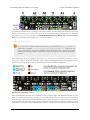
3.a. Features and components
The main features of the Zumo Shield (v1.2) are labeled in this diagram:
For the original Zumo Shield, a corresponding diagram [https://www.pololu.com/file/download/zumo-shield-v1.0-labeledcomponents.jpg?file_id=0J810] (206k jpg) is available (the only differences are the on-board inertial sensors).
Power
The Zumo chassis has an internal compartment for four AA batteries. We recommend using rechargeable AA
NiMH cells [https://www.pololu.com/product/1003], which results in a nominal voltage of 4.8 V (1.2 V per cell). You
can also use alkaline cells, which would nominally give you 6V.
A direct connection to the battery terminals is provided by the battery charger connector on the rear edge of
the shield, which can be used to recharge the Zumo’s batteries without removing them from the chassis. The
positive pin of the charge connector, on the left, is indicated by a plus sign (+). A charger like the iMAX-B6AC
[https://www.pololu.com/product/2588], connected by clipping its alligator clips to a pair of jumper wires inserted into
the charge connector, works well for charging the Zumo.
3. The Zumo Shield in detail
Page 25 of 42
Pololu Zumo Shield for Arduino User’s Guide
© 2001–2015 Pololu Corporation
After passing through reverse protection, the battery voltage is connected to the rest of the shield by the
power switch. The switched battery voltage is designated VBAT and provides power to the motors through the
DRV8835 motor driver. An on-board boost regulator, also supplied from VBAT, generates 7.45 V to power the
Arduino through its Vin pin. In turn, the Arduino’s regulated 5V and 3.3V voltages supply power to the motor
driver logic, buzzer circuit, and compass module on the Zumo Shield.
Warning: When powering the Arduino from the Zumo Shield, you must never connect a different
power supply to the Arduino’s VIN pin or plug a power supply into the Arduino’s power jack, as
doing so will create a short between the shield’s power supply and the Arduino’s power supply that
could permanently damage both the Arduino and the Zumo Shield.
When the Arduino is connected to a computer via USB, it will receive power (and supply 5V and
3.3V to the shield) even when the Zumo Shield’s power switch is off. This can be useful if you
want to test your Arduino program without allowing the motors to run, since turning the power
switch off disconnects motor power (VBAT).
LEDs
There are five LEDs on the Zumo Shield:
• A set of power LEDs, one blue and one red, is located in each of the two rear corners of the shield.
• A yellow user LED is located on the right edge of the shield. It is connected to digital pin 13 on the
Arduino, in parallel with the Arduino’s onboard user LED.
Pushbuttons
Two pushbuttons can be soldered to the Zumo Shield:
• The reset pushbutton is located on the left edge of the shield. It is connected to the Arduino’s RESET
pin and can be pressed to reset the Arduino.
• The user pushbutton is located on the rear edge of the shield. It is connected to digital pin 12 on
the Arduino; pressing the button pulls the pin low, and we recommend enabling the Arduino’s internal
pull-up to pull the pin high otherwise. The Pushbutton library, included with our Zumo Shield libraries
[https://www.pololu.com/docs/0J57/6], makes it easy to detect and debounce button presses with this pushbutton.
Motor driver
An integrated DRV8835 [https://www.pololu.com/product/2135] dual motor driver on the Zumo Shield drives the
Zumo’s two micro metal gearmotors. Four Arduino pins are used to control the driver:
• Digital pin 7 controls the right motor direction (LOW drives the motor forward, HIGH drives it in
reverse).
• Digital pin 8 controls the left motor direction.
• Digital pin 9 controls the right motor speed with PWM (pulse width modulation).
• Digital pin 10 controls the left motor speed with PWM.
3. The Zumo Shield in detail
Page 26 of 42
Pololu Zumo Shield for Arduino User’s Guide
© 2001–2015 Pololu Corporation
The ZumoMotors library [https://www.pololu.com/docs/0J57/6] provides functions that allow you to easily control
the motors, and it can optionally take care of flipping a direction signal for you if you accidentally soldered in a
motor backwards.
Buzzer
The Zumo Shield comes with a buzzer that can be used to generate simple sounds and music (for example, you
could use it to produce an audible countdown at the beginning of a sumo match). The buzzer control line is
labeled BZ on the shield; if you alternate between driving it high and low at a given frequency, the buzzer will
produce sound at that frequency.
The ZumoBuzzer library [https://www.pololu.com/docs/0J57/6] uses hardware PWM to play notes on the buzzer,
with digital pin 3 (OC2B) on an Arduino Uno or an older Arduino, or with digital pin 6 (OC4D) on an Arduino
Leonardo or A-Star 32U4 Prime. A jumper is provided to connect the BZ input to the appropriate Arduino
output, as detailed in Section 3.c.
Front expansion area
A number of I/O, power, and ground connections are brought to the front of the Zumo Shield to allow the
mounting of additional sensors and other components. The pinout of this front expansion area is detailed in
Section 3.b.
Inertial sensors
The Zumo Shield includes on-board inertial sensors, which can be used to sense acceleration and orientation for
advanced applications:
• The v1.2 Zumo Shield features an LSM303D 3-axis accelerometer and magnetometer and an L3GD20H
3-axis gyroscope.
• The original Zumo Shield features an LSM303DLHC 3-axis accelerometer and magnetometer.
The inertial sensors are detailed in Section 3.d.
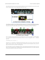
3.b. Front expansion
The pins in the front expansion area of the Zumo Shield are shown in the following diagram:
3. The Zumo Shield in detail
Page 27 of 42
Pololu Zumo Shield for Arduino User’s Guide
© 2001–2015 Pololu Corporation
This diagram is also available as a downloadable PDF: Zumo Shield front expansion pinout
[https://www.pololu.com/file/download/zumo_shield_front_expansion_pinout.pdf?file_id=0J592] (552k pdf).
The front expansion makes available digital pins 2, 4, 5, and 11 and analog pins A0 through A5. It also provides
access to the two I²C pins (SDA and SCL). However, please note that the I²C pins are not independent pins; they
are respectively duplicates of analog pins A4 and A5 on the Uno R3 and digital pins 2 and 3 on the Leonardo and
A-Star 32U4 Prime. Typically, you will only be able to use these pins for either I²C communication or general
I/O, not both. Additionally, pin A1 is used to monitor the battery voltage if you install the battery monitor jumper.
Please note that only components and connectors in the front three rows of pins can extend below the shield; the
fourth row covers the chassis and is only suitable for components mounted above the shield.
If you use an Arduino Uno R2 or an older Arduino, which lack separate I²C pins, the SDA and SCL pins on the
Zumo Shield will not be connected to anything. To use an I²C device on those pins, you can connect SDA to A4
and SCL to A5 yourself by bridging across those two sets of pins in the front expansion area. Section 3.c further
explains the I²C lines and the jumpers connecting them to the on-board compass module.
Depending on the Arduino model, digital pin 3 or 6 is used to control the buzzer if you install
the buzzer control jumper. If you are using an Uno, pin 6 will be available for general-purpose
I/O. If you are using a Leonardo or A-Star, pin 3 will be available if you are not using I²C. These
pins are not accessible via the front expansion, but they can be accessed from other points on
the shield and used for interfacing with additional electronics if free. Additionally, digital pin 12
can be used for interfacing with many types of additional electronics, especially if you are not
using the shield’s user pushbutton. Pin 12 is completely free when the pushbutton is in its default,
unpressed state, and it is pulled low through a 1k resistor when the pushbutton is pressed.
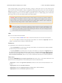
3.c. Jumper settings
The Zumo shield has several jumpers that let you change the way it is connected to the Arduino, as shown in the
picture below.
3. The Zumo Shield in detail
Page 28 of 42
Pololu Zumo Shield for Arduino User’s Guide
© 2001–2015 Pololu Corporation
• The battery level jumper connects the Arduino’s analog pin 1 to a voltage divider circuit that allows
you to monitor the Zumo’s battery voltage. This jumper is disconnected by default and can be connected by
soldering a short length of wire between the two holes.
The divider outputs a voltage equal to two-thirds of the battery voltage, which will always be safely below the
Arduino’s maximum analog input voltage of 5 V. For example, at a battery voltage of 4.8 V, analog pin 1 will be
at a level of 3.2 V. Using Arduino’s analogRead() function, where 5 V is read as a value of 1023, 3.2 V is read
as a value of 655. To convert it back to the actual battery voltage, multiply this number by 5000 mV×3/2 and
divide by 1023:
unsigned int batteryVoltage = analogRead(1) * 5000L * 3/2 / 1023;
• The buzzer control jumper connects one of the Arduino’s PWM outputs to the buzzer on the Zumo
Shield. This jumper is disconnected by default on both the assembled and kit versions of the Zumo robot; it
must be connected to enable the buzzer.
If you have an Arduino Uno or an older Arduino (with an ATmega328P or ATmega168 microcontroller), you
should jumper the two holes bracketed with the label 328P to connect the BZ pin to digital pin 3. If you have an
A-Star 32U4 Prime or Arduino Leonardo, you should jumper the two holes bracketed with the label 32U4 to
connect the BZ pin to digital pin 6. These are the pins our ZumoBuzzer library [https://www.pololu.com/docs/0J57/6]
expects the buzzer to be connected to for each respective microcontroller. More details about the buzzer can be
found in Section 3.a.
3. The Zumo Shield in detail
Page 29 of 42
Pololu Zumo Shield for Arduino User’s Guide
© 2001–2015 Pololu Corporation
• The compass/gyro I²C jumpers connect the I²C clock (SCL) and data (SDA) lines of the inertial sensors
on the Zumo Shield to the SCL and SDA pins on the Arduino. These jumpers are connected by default, but
can be disconnected by cutting the thin trace between each pair of holes.
On the Arduino Uno R3, SCL and SDA are duplicates of analog pins 5 and 4, respectively. On the A-Star and
Arduino Leonardo, SCL and SDA are duplicates of digital pins 3 and 2, respectively. Using the I²C sensors on
the shield will prevent these pins from being used for other purposes, and the I²C pull-up resistors will affect
readings on these pins even if the compass is not being actively used, so you must cut the jumpers to disconnect
the inertial sensors and pull-ups if you want to repurpose the SCL and SDA pins.
Please note that the SCL and SDA pins do not exist on Arduino hardware versions prior to the Uno R3, so you
will have to manually connect SCL to analog pin 5 and SDA to analog pin 4 on the Zumo Shield in order to use
the compass with an older Arduino. The most convenient place to do this is in the front expansion area, where
these pins are all located together, as indicated by the light blue boxes in the picture above.
More details about the inertial sensors can be found in Section 3.d.
Instead of making a wire connection, you can solder a 1×3 male header to the buzzer jumper holes
to allow the use of a shorting block for connecting the buzzer (note: this header is already installed
if you got the assembled version of the Zumo robot, but the shorting block must be positioned
in the appropriate place for the Arduino model you are using). You can also use male headers
and shorting blocks for the battery level jumper and compass jumpers if you have an Arduino
Uno with an SMD (surface mount) microcontroller, Arduino Leonardo, or A-Star 32U4 Prime.
However, there is not enough clearance to use male headers on the battery level and compass I²C
jumpers if you are using an Arduino with a DIP (through-hole) microcontroller.
3.d. Inertial sensors (accelerometer, magnetometer, and gyro)
Overview
The Zumo Shield includes on-board inertial sensors that can be used in advanced applications, such as helping
your Zumo detect collisions and determine its own orientation.
All versions of the Zumo Shield have a compass module that combines a 3-axis accelerometer and 3-axis
magnetometer into a single package with an I²C interface. This chip is an LSM303D
[https://www.pololu.com/product/2127] on the v1.2 shield or an LSM303DLHC [https://www.pololu.com/product/2124] on
the original Zumo Shield.
The v1.2 version of the Zumo Shield also adds an L3GD20H
gyroscope on the same I²C bus.
We
[https://www.pololu.com/product/2129]
3-axis
recommend
carefully reading the LSM303D datasheet [https://www.pololu.com/file/download/
(1MB
pdf),
L3GD20H
datasheet [https://www.pololu.com/file/download/
L3GD20H.pdf?file_id=0J731] (3MB pdf), and/or LSM303DLHC datasheet [https://www.pololu.com/file/download/
LSM303DLHC.pdf?file_id=0J564] (629k pdf) to understand how these sensors work and how to use them.
LSM303D.pdf?file_id=0J703]
Using the sensors
Level shifters built into the shield allow the inertial sensors, which operate at 3.3 V, to be connected to the 5 V
logic level pins of the Arduino. The sensors, level shifters, and I²C pull-up resistors are connected to the SCL
3. The Zumo Shield in detail
Page 30 of 42
Pololu Zumo Shield for Arduino User’s Guide
© 2001–2015 Pololu Corporation
and SDA pins on the Zumo Shield by default, but they can be disconnected by cutting traces to allow those pins
to be used for other purposes. It is necessary to make some additional connections on the shield if you want to
use the compass with an older Arduino without separate SCL and SDA pins; please see Section 3.c for more
details about the compass connections.
We have written a basic LSM303 Arduino library [https://github.com/pololu/lsm303-arduino] and L3G Arduino
library [https://github.com/pololu/l3g-arduino] that makes it easier to interface the sensors with an Arduino, as well
as an example project [https://www.pololu.com/docs/0J57/7.f] that demonstrates how to use the magnetometer to help
the Zumo coordinate its turns.
In addition, the combination of accelerometer, magnetometer, and gyro on the v1.2 version of the Zumo
Shield is enough to implement an inertial measurement unit (IMU); the sensor ICs are the same as those on
our MinIMU-9 v3 [https://www.pololu.com/product/2468], so Arduino software written for the MinIMU-9 (such as
our AHRS example [https://github.com/pololu/minimu-9-ahrs-arduino]) can also be adapted to work on an Arduinocontrolled Zumo robot with a v1.2 shield.
Notes on the magnetometer
Please note that the magnetometer in the LSM303 is affected by currents in the motors and buzzer when they
are operating, as well as metal in the batteries, and the readings are easily influenced by magnetic distortions in
the environment around the Zumo (such as rebar in a concrete floor). As a result, it is very hard to accurately
determine the Zumo’s absolute heading based on the magnetometer data. However, in our tests, we found that
the magnetometer was still useful for detecting relative orientation changes; for example, once the magnetic
readings are compensated for a particular environment, they can be used to help the Zumo turn left or right by a
specific angle instead of just timing how long to run the motors to make such a turn.
In our tests, we found that the batteries, motors, and motor current affect the z axis of the
magnetometer much more strongly than the x and y axes, so you probably will want to ignore
the z readings. We were generally able to get decent results using only the x and y magnetometer
readings to determine heading. Additionally, you might need to decrease the magnetometer
sensitivity; if the magnetometer returns a value of -4096, that is a sign that the sensitivity range is
set too narrow for your particular environment.
3. The Zumo Shield in detail
Page 31 of 42
Pololu Zumo Shield for Arduino User’s Guide
© 2001–2015 Pololu Corporation
4. Schematic diagrams
Schematic diagrams of the Zumo Shield are available as a downloadable PDF:
• v1.2
v1_2-schematic.pdf?file_id=0J779]
Zumo
Shield
schematic
(449k pdf)
• Original
Shield
Zumo
zumo_shield_schematic.pdf?file_id=0J591]
4. Schematic diagrams
diagrams
schematic
(121k pdf)
[https://www.pololu.com/file/download/zumo-shield-
diagrams
[https://www.pololu.com/file/download/
Page 32 of 42
Pololu Zumo Shield for Arduino User’s Guide
© 2001–2015 Pololu Corporation
5. Arduino pin assignment table
Digital
pins
Zumo Shield function
Notes/alternate functions
0
digital I/O
RX for programming and serial communication on Uno and older Arduinos
1
digital I/O
TX for programming and serial communication on Uno and older Arduinos
2
digital I/O (front expansion)
I²C SDA on Leonardo and A-Star 32U4 Prime
3
digital I/O
optional jumper to buzzer control line for Uno and older Arduinos
I²C SCL on Leonardo and A-Star 32U4 Prime
4
digital I/O (front expansion)
5
digital I/O (front expansion)
6
digital I/O
7
right motor direction control line
8
left motor direction control line
9
right motor PWM control line
10
left motor PWM control line
11
digital I/O (front expansion)
12
digital I/O
user pushbutton (pressing pulls low)
13
digital I/O
yellow user LED (high turns LED on)
Analog pins
optional jumper to buzzer control line for Leonardo and A-Star 32U4 Prime
Zumo Shield function
Notes/alternate functions
A0
analog input and digital I/O (front expansion)
A1
analog input and digital I/O (front expansion) optional jumper to battery level voltage divider
A2
analog input and digital I/O (front expansion)
A3
analog input and digital I/O (front expansion)
A4
analog input and digital I/O (front expansion) I²C SDA on Uno and older Arduinos
A5
analog input and digital I/O (front expansion) I²C SCL on Uno and older Arduinos
5. Arduino pin assignment table
Page 33 of 42
Pololu Zumo Shield for Arduino User’s Guide
© 2001–2015 Pololu Corporation
6. Zumo Shield Arduino Libraries
Our Zumo Shield Libraries make it easy to get started writing Arduino sketches to control your Zumo. A link to
download the library and installation instructions can be found on the libraries’ github page [https://github.com/
pololu/zumo-shield].
Once installed, we recommend you try out the example sketches for each library, which can be found under
File > Examples > (name of the library), to get a better understanding of how to use the library functions. You
can also find some more complex examples, not specific to any particular library, under File > Examples >
ZumoExamples; Section 7 describes these examples in detail.
The Zumo Shield Libraries include the following:
ZumoMotors
The ZumoMotors library provides functions for PWM-based speed (and direction) control of the two motors
on the Zumo with the onboard DRV8835 dual motor driver. On Arduinos with ATmega328P, ATmega168,
and ATmega32U4 microcontrollers (which include the A-Star 32U4 Prime, Arduino Leonardo, Arduino Uno,
and most older Arduinos), the motor control functions use hardware PWM outputs from Timer1 to generate
pulse width modulation at a 20 kHz frequency. (See Section 3 for more details about the motor driver and its
connections.)
If you accidentally soldered a motor to the Zumo Shield backwards (opposite the orientation indicated in the
assembly instructions [https://www.pololu.com/docs/0J57/2.b]), you can simply call flipLeftMotor(true) and/or
flipRightMotor(true) to make the motors behave consistently with the directions in your code.
ZumoBuzzer
The ZumoBuzzer library provides functions that allow various sounds to be played on the buzzer of the Zumo
Shield, from simple beeps to complex tunes. (See Section 3 for more details about the buzzer and Section 3.c
for an explanation of the buzzer control jumper settings.)
The ZumoBuzzer library is fully compatible with the OrangutanBuzzer [https://www.pololu.com/docs/0J18/3]
functions in the Pololu AVR C/C++ Library [https://www.pololu.com/docs/0J20], so any melodies written for
OrangutanBuzzer functions will also work with ZumoBuzzer functions.
Pushbutton
The Pushbutton library provides a set of functions that are useful for detecting and debouncing pushbutton
presses. While the most obvious application of this library is to work with the Zumo Shield’s user pushbutton
on digital pin 12, this library can be used as a general-purpose library for interfacing many types of buttons and
switches to an Arduino, even without a Zumo Shield.
ZumoReflectanceSensorArray
This library provides a set of functions for reading reflectance values from a Zumo reflectance sensor array
[https://www.pololu.com/product/1419]. See Section 2.c for more information on the Zumo reflectance sensor array.
This library depends on the QTRSensors library. The ZumoReflectanceSensorArray class is a subclass of
QTRSensorsRC. The functions provided by QTRSensorsRC can also be used on the
ZumoReflectanceSensorArray class, and are documented in the Arduino Library for the Pololu QTR
Reflectance Sensors document [https://www.pololu.com/docs/0J19].
6. Zumo Shield Arduino Libraries
Page 34 of 42
Pololu Zumo Shield for Arduino User’s Guide
© 2001–2015 Pololu Corporation
QTRSensors
This library, which can also be found in the qtr-sensors-arduino repository [https://github.com/pololu/qtr-sensorsarduino], is a general library for interfacing with Pololu QTR reflectance sensors [https://www.pololu.com/category/
123/pololu-qtr-reflectance-sensors]. Since the Zumo reflectance sensor array [https://www.pololu.com/product/1419] has
the same interface as the QTR RC reflectance sensors, the ZumoReflectanceSensorArray library uses
QTRSensors to read the sensor array.
6. Zumo Shield Arduino Libraries
Page 35 of 42
Pololu Zumo Shield for Arduino User’s Guide
© 2001–2015 Pololu Corporation
7. Example projects
These examples demonstrate how to program an Arduino-controlled Zumo to perform more complex and
interesting tasks. The source files for the examples are included in the download for the Zumo Shield Arduino
Libraries [https://www.pololu.com/docs/0J57/6]. Once the libraries are installed, the examples can be accessed in the
Arduino environment under File > Examples > ZumoExamples.
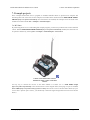
7.a. RC Zumo
By connecting an RC receiver and running this example program, you can turn your Zumo into a radio-controlled
vehicle. With the Zumo Shield Arduino Libraries [https://www.pololu.com/docs/0J57/6] installed, the sketch file can
be opened in Arduino by selecting File > Examples > ZumoExamples > RCControl.
A Zumo robot with an RC receiver
attached to make a radio-controlled
vehicle.
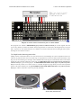
An easy way to connect the receiver to the Zumo Shield is to solder two 1×3 male header strips
[https://www.pololu.com/product/966] to the locations shown in the diagram below, then plug in a pair of standard
servo cables [https://www.pololu.com/category/112/servo-cables] between the receiver and the Zumo Shield. (If your
receiver has a separate power source, you should only connect the signal and ground wires between it and the
Zumo.)
7. Example projects
Page 36 of 42
Pololu Zumo Shield for Arduino User’s Guide
© 2001–2015 Pololu Corporation
Diagram of an RC receiver connected to pins on a Zumo Shield.
This program uses Arduino’s PulseIn library [http://arduino.cc/en/Reference/PulseIn] to read the signals from the
receiver. By default, it assumes the throttle and steering channels are connected as the diagram shows on pins 4
and 5, respectively. The signals from the two channels are mixed to determine the left and right motor speeds,
allowing for more intuitive control.
7.b. Simple border-detecting sumo robot
Adding sensors to the Zumo allows it to sense and react to its surroundings. In a sumo competition where two
robots try to push each other out of a circular ring, it is important for a robot to be able to detect the border of the
ring so it can avoid driving over the edge. Since standard robot sumo rings are colored black with a white border
around the edge, infrared reflectance sensors like our QTR sensors [https://www.pololu.com/category/123/pololu-qtrreflectance-sensors] are great for this purpose. The Zumo Reflectance Sensor Array [https://www.pololu.com/product/
1419] conveniently mounts six of these sensors in a module designed to plug directly into the front expansion
header of the Zumo Shield (note: the pre-assembled version of the Zumo robot [https://www.pololu.com/product/
2510] ships with this reflectance sensor array already installed).
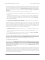
A Zumo robot preparing to attack a
Parallax SumoBot.
7. Example projects
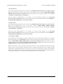
Zumo reflectance sensor array on a
Zumo robot, bottom view.
Page 37 of 42
Pololu Zumo Shield for Arduino User’s Guide
© 2001–2015 Pololu Corporation
This example demonstrates how to program an Arduino-controlled Zumo equipped with a reflectance sensor
array to drive around and stay within a sumo ring. Note that it only uses the two outermost sensors on the array,
which are sufficient for border detection. With the Zumo Shield Arduino Libraries [https://www.pololu.com/docs/
0J57/6] installed, the sketch file can be opened in Arduino by selecting File > Examples > ZumoExamples >
BorderDetect.
You might need to edit a few things in this sketch to make it work well with your Zumo:
• If one or both of your motors have been connected backwards, uncomment lines 48 and/or 49 to correct
their directions.
• Adjust the speeds and durations in lines 13-17. Generally, lower speeds and shorter durations should
work better with faster motors, while higher speeds and longer durations should be more appropriate for
slower motors. We found that these default values worked well with a Zumo using 75:1 HP motors
[https://www.pololu.com/product/2361].
• Finally, the sensor reading threshold used to differentiate between black and white surfaces, defined on
line 10, might need to be changed to suit your environment.
Upload the sketch to an Arduino mounted on a Zumo, place the Zumo on a sumo ring (or a similar large dark
surface with a light border), and press the user pushbutton. Be ready to catch the Zumo in case it drives off
the ring! If everything works right, the Zumo should sound a countdown with its buzzer and then start driving
forward until it detects the ring border; it should then back up, turn, and continue. If not, try adjusting some of
the parameters as described above. Here are some specific troubleshooting tips:
• If the Zumo overshoots the ring border, try lowering FORWARD_SPEED (especially if it is going very fast)
or reducing QTR_THRESHOLD.
• If the Zumo stops at the border but turns too much or not enough before continuing, adjust TURN_SPEED
and/or TURN_DURATION.
• If you do not hear any sound from the buzzer, make sure you have the buzzer control jumper
[https://www.pololu.com/docs/0J57/3.c] configured correctly for your Arduino.
The ability to wander around while staying inside a sumo ring is enough to allow a Zumo to compete as a basic
sumo robot, but a more advanced robot might be able to detect its opponent and drive toward it directly. As a
next step, you might consider adding more sensors, such as range finders [https://www.pololu.com/category/79/opticalrange-finders], to allow the Zumo to find its opponent instead of relying on luck to make contact.
7.c. Collision-detecting sumo robot
This example extends the simple border-detecting sumo robot example [https://www.pololu.com/docs/0J57/7.b]
described in the previous section, making use of the accelerometer in the Zumo Shield’s LSM303 3-axis compass
module (described in section Section 3.d) to detect collisions. With the Zumo Shield Arduino Libraries
[https://www.pololu.com/docs/0J57/6] installed, the sketch file can be opened in Arduino by selecting File > Examples
> ZumoExamples > SumoCollisionDetect. This example also requires the LSM303 library [https://github.com/
pololu/lsm303-arduino] to be installed.
This program uses the X and Y components of the acceleration measured by the LSM303 to determine when it
has made contact with an adversary robot in a sumo competition. When it detects contact, the Zumo speeds up,
which should allow it to either more effectively push the opponent out of the ring or to escape the opponent if
it collided at an undesired angle (from the rear or side). To read more about how this program works, please see
the comments contained in SumoCollisionDetect.ino.
7. Example projects
Page 38 of 42
Pololu Zumo Shield for Arduino User’s Guide
© 2001–2015 Pololu Corporation
7.d. Line follower
This example program demonstrates how a Zumo with a reflectance sensor array [https://www.pololu.com/product/
1419] can be programmed to follow lines and run a line-following course. With the Zumo Shield Arduino
Libraries [https://www.pololu.com/docs/0J57/6] installed, the sketch file can be opened in Arduino by selecting File
> Examples > ZumoExamples > LineFollower.
This line follower implementation is very similar to our line following example for the 3pi robot
[https://www.pololu.com/product/975], and the concepts and strategies involved are explained in detail in Section 7 of
the 3pi robot user’s guide [https://www.pololu.com/docs/0J21].
7.e. Maze solver
This example program demonstrates how a Zumo with a reflectance sensor array [https://www.pololu.com/product/
1419] can be programmed to solve a line maze. With the Zumo Shield Arduino Libraries
[https://www.pololu.com/docs/0J57/6] installed, the sketch file can be opened in Arduino by selecting File > Examples
> ZumoExamples > MazeSolver.
This maze solver implementation is very similar to our maze solving example for the 3pi robot
[https://www.pololu.com/product/975], and the concepts and strategies involved are explained in detail in Section 8 of
the 3pi robot user’s guide [https://www.pololu.com/docs/0J21].
7.f. Using the compass
This example program demonstrates using the magnetometer in the Zumo Shield’s LSM303 3-axis compass
module (described in section Section 3.d) to help the Zumo coordinate ninety-degree turns and drive in squares.
With the Zumo Shield Arduino Libraries [https://www.pololu.com/docs/0J57/6] installed, the sketch file can be
opened in Arduino by selecting File > Examples > ZumoExamples > Compass. This example also requires the
LSM303 library [https://github.com/pololu/lsm303-arduino] to be installed.
Because the batteries, motors, and motor current affect the z axis of the magnetometer much more strongly
than the x and y axes, this program calculates the Zumo’s orientation using only the x and y readings from the
magnetometer, assuming that the robot is always level. In order to prevent external, locally varying magnetic
fields (e.g. from rebar in a concrete floor) from affecting the Zumo’s navigation too much, the program measures
the magnetic heading before each turn, then turns ninety degrees relative to that heading.
7. Example projects
Page 39 of 42
Pololu Zumo Shield for Arduino User’s Guide
© 2001–2015 Pololu Corporation
8. Controlling a servo
This section explains how to control a hobby RC servo [https://www.pololu.com/category/23/rc-servos] from an
Arduino Uno, Arduino Leonardo, or A-Star 32U4 Prime that is connected to the Zumo Shield. The Arduino
IDE includes a Servo [http://arduino.cc/en/Reference/Servo] library that generates the pulses needed to control an RC
servo. However, this servo library conflicts with the ZumoMotors library in that both rely on Timer 1. Instead,
you will need to do something special to get servo control working.
To control a servo with an Arduino Uno, see Section 8.a. To control a servo with an Arduino Leonardo or A-Star
32U4 Prime, see Section 8.b.
8.a. Controlling a servo with an Arduino Uno
The example Arduino Uno code below shows how to control a single servo using Timer 2. Because it uses Timer
2 instead of Timer 1, this code does not interfere with the ZumoMotors library, but it will interfere with the
ZumoBuzzer library, so you will not be able to use this and the buzzer at the same time. You can integrate this
code with other code that drives the motors.
/** Arduino Uno Timer 2 Servo Example
This example code for the Arduino Uno shows how to use Timer 2 on
the ATmega328P to control a single servo. This can be useful for
people who cannot use the Arduino IDE's Servo library. For
example, the ZumoMotors library uses the same timer as the Servo
library (Timer 1), so the two libraries conflict.
The SERVO_PIN macro below specifies what pin to output the
servo on. This pin needs to be connected to the signal input
line of the servo. The Arduino's GND needs to be connected to
the ground pin of the servo. The servo's ground and power pins
need to be connected to an appropriate power supply.
*/
// This line specifies what pin we will use for sending the
// signal to the servo. You can change this.
#define SERVO_PIN 11
// This is the time since the last rising edge in units of 0.5us.
uint16_t volatile servoTime = 0;
// This is the pulse width we want in units of 0.5us.
uint16_t volatile servoHighTime = 3000;
// This is true if the servo pin is currently high.
boolean volatile servoHigh = false;
void setup()
{
servoInit();
}
void loop()
{
servoSetPosition(1000);
delay(1000);
servoSetPosition(2000);
delay(1000);
}
// Send 1000us pulses.
// Send 2000us pulses.
// This ISR runs after Timer 2 reaches OCR2A and resets.
// In this ISR, we set OCR2A in order to schedule when the next
// interrupt will happen.
// Generally we will set OCR2A to 255 so that we have an
// interrupt every 128 us, but the first two interrupt intervals
// after the rising edge will be smaller so we can achieve
// the desired pulse width.
ISR(TIMER2_COMPA_vect)
{
8. Controlling a servo
Page 40 of 42
Pololu Zumo Shield for Arduino User’s Guide
© 2001–2015 Pololu Corporation
// The time that passed since the last interrupt is OCR2A + 1
// because the timer value will equal OCR2A before going to 0.
servoTime += OCR2A + 1;
static uint16_t highTimeCopy = 3000;
static uint8_t interruptCount = 0;
if(servoHigh)
{
if(++interruptCount == 2)
{
OCR2A = 255;
}
// The servo pin is currently high.
// Check to see if is time for a falling edge.
// Note: We could == instead of >=.
if(servoTime >= highTimeCopy)
{
// The pin has been high enough, so do a falling edge.
digitalWrite(SERVO_PIN, LOW);
servoHigh = false;
interruptCount = 0;
}
}
else
{
// The servo pin is currently low.
}
}
if(servoTime >= 40000)
{
// We've hit the end of the period (20 ms),
// so do a rising edge.
highTimeCopy = servoHighTime;
digitalWrite(SERVO_PIN, HIGH);
servoHigh = true;
servoTime = 0;
interruptCount = 0;
OCR2A = ((highTimeCopy % 256) + 256)/2 - 1;
}
void servoInit()
{
digitalWrite(SERVO_PIN, LOW);
pinMode(SERVO_PIN, OUTPUT);
// Turn on CTC mode. Timer 2 will count up to OCR2A, then
// reset to 0 and cause an interrupt.
TCCR2A = (1 << WGM21);
// Set a 1:8 prescaler. This gives us 0.5us resolution.
TCCR2B = (1 << CS21);
// Put the timer in a good default state.
TCNT2 = 0;
OCR2A = 255;
}
TIMSK2 |= (1 << OCIE2A); // Enable timer compare interrupt.
sei();
// Enable interrupts.
void servoSetPosition(uint16_t highTimeMicroseconds)
{
TIMSK2 &= ~(1 << OCIE2A); // disable timer compare interrupt
servoHighTime = highTimeMicroseconds * 2;
TIMSK2 |= (1 << OCIE2A); // enable timer compare interrupt
}
8. Controlling a servo
Page 41 of 42
Pololu Zumo Shield for Arduino User’s Guide
© 2001–2015 Pololu Corporation
8.b. Controlling a servo with an Arduino Leonardo or A-Star 32U4 Prime
It is possible to modify the Servo library that comes with the Arduino IDE to use Timer 3 instead of Timer
1 on the Arduino Leonardo or A-Star 32U4 Prime. The modified Servo library does not interfere with the
ZumoMotors library, making it possible to simultaneously control servos and the motors.
Warning: The modifications described here will affect any sketch for the Arduino Leonardo or AStar that uses the Servo library.
1. First, you will need to locate the Arduino IDE’s Servo library, and find the file inside it named
ServoTimers.h. For the 1.6.x versions of the IDE, this file can be found in libraries/Servo/src/avr/
ServoTimers.h. If you are using Mac OS X, you will need to right-click on the Arduino IDE icon and select
“Show Package Contents” to see the files inside.
2. Open ServoTimers.h in a text editor.
3. Locate the following lines of code in ServoTimers.h:
#elif defined(__AVR_ATmega32U4__)
#define _useTimer1
typedef enum { _timer1, _Nbr_16timers } timer16_Sequence_t ;
4. The lower two lines of code specify that the library should use Timer 1. To use Timer 3 instead, just
change _useTimer1 to _useTimer3 and _timer1 to _timer3.
5. Save the file.
The Arduino IDE will automatically incorporate your modifications to the Servo library. The next time you
compile a sketch for the Arduino Leonardo or A-Star that uses the Servo library, it will use Timer 3 instead of
Timer 1.
8. Controlling a servo
Page 42 of 42