1
Home
S O I L
Contents
ThetaProbe
W A T E R
M O N I T O R I N G
THETAPROBE®
Methodology
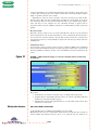
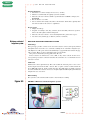
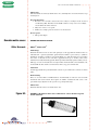
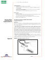
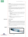
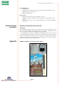
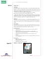
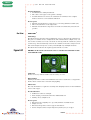
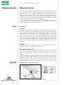
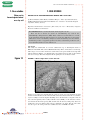
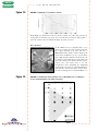
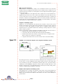
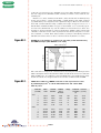
The ThetaProbe (Figure 6.14) avoids the limitations of an access tube by using steel
spikes driven into the soil as the capacitance plates. Whereas the permanently
installed multi-sensor products have one circuit that analyses each sensor serially,
each ThetaProbe has its own measurement electronics within the probe head. The
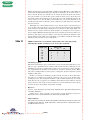
instrument can be either inserted into the soil surface to make one-off readings, or
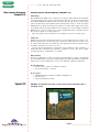
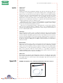
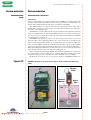
buried for continuous in situ readings. If you bury it, you should install it with an
extension tube (Figure 6.14). These tubes can be left in the ground and the
ThetaProbe inserted or removed when required.
Calibration
The probe outputs a measurement in volts. A calibration is then applied to the raw
voltage to give volumetric water content. The literature states there is a virtually linear relationship between the voltage (0 to 1 V) and the SWC (0 to 0.5 m3/m3). Two
‘generalised’ calibrations for ‘mineral’ and ‘organic’ soils are provided; these guarantee an accuracy of 5% (0.05 m3/m3). Use a two-point calibration if you want to achieve
an accuracy of 1% (0.01 m3/m3).
Data handling
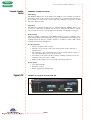
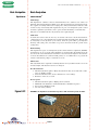
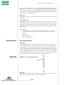
A handheld display (ThetaMeter) is provided. This applies the operating voltage (5 to
15 V DC) and outputs either raw voltage readings or volumetric water content using
the two ‘generalised’ calibrations. Alternatively, you can use a voltmeter and DC
power supply or standard logger and apply the calibration in a spreadsheet.
Maintenance
The manufacturer states that no maintenance is required.
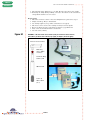
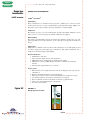
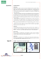
Figure 6.14
FIGURE 6.14 ThetaProbe. (Top length = 200 mm, diameter = 40 mm.)
Bottom shows installation suggestion and ThetaMeter.
PAGE 34