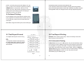
1
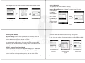
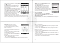
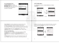
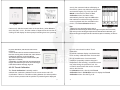
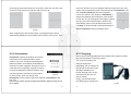
EPX300 Hardness Tester USER’S MANUAL Please Carefully Read This First LIPPOLIS optical video technology www.lippolis.com e-mail: [email protected] Contents CAUTION……………………………………………………………………1 1. SUMMARIZE……………………………………………………………2 1.1 Measuring principle scope……………………………………………2 1.2 The hardness value "L"…………………………………………………5 1.3 Main features……………………………………………………………6 1.4 Application range………………………………………………………7 1.5 Technical information…………………………………………………8 1.5.1 Display unit……………………………………………………………8 1.5.2 Impact Devices ………………………………………………………9 1.5.2.1 Impact Device D……………………………………………………9 1.5.2.2 Impact Device DC…………………………………………………10 1.5.2.3 Impact Device DL…………………………………………………11 I 4.1.1 Button…………………………………………………………………24 4.1.2 Measure mode………………………………………………………25 4.1.3 Adjusting the LCD Contrast Manually……………………………27 4.1.4 Select the Type of Impact Device…………………………………29 4.2 USING THE MENU……………………………………………………30 4.2.1 Testing Setup………………………………………………………32 4.2.1.1 Material Group……………………………………………………34 4.2.1.2 Impact Direction…………………………………………………38 4.2.1.3 Scale………………………………………………………………40 4.2.1.4 Limit Values………………………………………………………42 4.2.1.5 Statistic……………………………………………………………43 4.2.2 Printing Setup………………………………………………………45 4.2.2.1 Items………………………………………………………………46 III 1.5.2.4 Impact Device C…………………………………………………12 1.5.2.5 Impact Device D+15………………………………………………13 1.5.2.6 Impact Device G…………………………………………………14 1.5.2.7 Support Rings……………………………………………………17 1.5.2.8 Application Criteria………………………………………………18 1.6 Overview the display unit……………………………………………20 2. CHECKING SUPPLIED ACCESSORIES……………………………21 3. QUICK START GUIDE…………………………………………………22 3.1 Connecting……………………………………………………………22 3.2 Charge the Battery……………………………………………………23 3.3 Calibrate the Instrument………………………………………………23 4. OPERATING INSTRUCTIONS………………………………………24 4.1 Display unit……………………………………………………………24 II 4.2.2.2 Print Memory………………………………………………………47 4.2.2.3 Print All……………………………………………………………49 4.2.3 Memory Management………………………………………………50 4.2.3.1 The Format of Memory Data……………………………………52 4.2.3.2 Data Browser Mode………………………………………………53 4.2.3.3 Delete Memory Data……………………………………………56 4.2.3.3.1 Delete Memory Data in Data Browser Menu………………56 4.2.3.3.2 Delete Selected…………………………………………………56 4.2.3.3.3 Delete All…………………………………………………………58 4.2.4 System Setting………………………………………………………59 4.2.4.1 System Function Switch…………………………………………59 4.2.4.2. Language………………………………………………………….62 4.2.4.3 Date / Time………………………………………………………62 IV 4.2.4.4 Backlight Time……………………………………………………64 4.2.5 Calibration……………………………………………………………66 4.2.5.1 Test Calibration……………………………………………………67 4.2.5.2 Touch calibration…………………………………………………71 4.2.6 Information…………………………………………………………75 4.3 Charging………………………………………………………………76 4.4 Backlight………………………………………………………………78 4.5 Reset……………………………………………………………………78 4.6 Automatic Shutdown…………………………………………………78 5. DATA PRINTING………………………………………………………80 5.1 Printer link………………………………………………………………80 5.2 Infrared Printing………………………………………………………81 5.3 Test Report Format……………………………………………………83 V 9.3 Normal Maintenance Procedures …………………………………97 9.4 Service …………………………………………………………………98 Appendix1. DAILY CHECKING………………………………………100 Appendix2. FACTORS AFFECTING THE ACCURACY……………101 1) Roughness of Sample Surface ……………………………………101 2) The shape of Sample Surface ………………………………………102 3) The Weight of the Sample …………………………………………102 4) The Sample Stability …………………………………………………103 Appendix3. SCALE RANGE- D & DC Type…………………………104 Appendix4. SCALE RANGE- DL Type ……………………………105 Appendix5. SCALE RANGE- C Type ………………………………106 Appendix6. SCALE RANGE- D+15 Type …………………………107 Appendix7. SCALE RANGE- G Type ………………………………108 VII 5.4 Test Report Printing…………………………………………………84 5.4.1 Automatic Printing…………………………………………………84 5.4.2 Manual Printing……………………………………………………85 5.4.3 Assemble Printing…………………………………………………86 5.4.4 The other Printing Ways……………………………………………86 6. HARDNESS TEST……………………………………………………88 6.1 Test Preparation………………………………………………………88 6.2 Sample Preparation…………………………………………………88 7. TEST STEPS……………………………………………………………92 8. TROUBLES AND SOLUTIONS………………………………………95 9. MAINTENANCE AND SERVICE……………………………………96 9.1 Impact Device Maintenance …………………………………………96 9.2 Store the Report ………………………………………………………96 VI VIII 1. SUMMARIZE CAUTION 1.1 Measuring Principle Scope Please Carefully Read This First 1. Users can only use the special battery and power adapter offered by our company in display unit, or may cause damage to products, battery leakage, even fire or explosion. 2. Any components of the product cannot be submerged in water and exposed in the rain, which could cause a battery explosion, and display unit damage. 3. To avoid electrical shock, do not open the cabinet. 4. Even if the instrument is not used for a long time, store it in a dry and cool place after fully charging it once per year. This is to maintain the battery functions. 1 the impact body generates an induction voltage in the single coil of the impact device. The voltage of the signal is proportional to the velocity of the impact body, and signal processing by the electronics provides the hardness reading for display and storage. Simply put, harder materials produce higher rebound velocity than those which are less hard (higher L value). EPX5500 is a direct hardness measurement within any particular material group (i.e. steel, aluminum, etc.) and can be used as a final test result without conversion. However, EPX5500 has established conversions to other EPX5500 measuring principle is physically a rather simple, dynamic hardness test. An impact body with a hard metal test tip is propelled by spring force against the surface of the test piece. Surface deformation takes place when the impact body hits the test surface, which will result in loss of kinetic energy. This energy loss is calculated by velocity measurements when the impact body is at a precise distance from the surface for both the impact and rebound phase of the test. The permanent magnet in 2 hardness scales for the convenience of our customers. These conversions to other scales (HRC, HRB, HB, HV, HSD etc.) are programmed into the electronics, and can be shown directly on the display as the test result. All data is stored in the native L scale to prevent any possible errors with multiple conversions. 3 4 1.2 The Hardness Value "L" 1.3 Main Features: This term, 1978 introduced by Doctor Dietmar Leeb into measuring technology, is the quotient for the impact body's rebound and impact velocity, multiplied by 1000. Harder materials produce higher rebound velocity than those which are less hard. With reference to a particular material group (e.g. steel, aluminum etc.) the L-value represents a direct hardness measurement and is used as such. Comparison curves with standard static hardness values have been established (Brinell, Vickers, Rockwell C, B) for the most prevalent materials, enabling the L values to be converted into the relevant values for these procedures. With EPX5500, such hardness values can be directly displayed in the hardness scales HRC, HRB, HB, HV, HSD and tensile strength (MPa). Highly accurate ± 6 HL Automatic correction for impact direction Large, easy to read display with backlight Manu language: English, Deutsch, French, Italian, Spanish, Russian, Chinese Simplified, Chinese Traditional User profiles for fast change of all settings To operate with touch screen Large memory with on-screen review of data Converts to all common hardness scales (HV, HB, HRC, HRB, HSD) and tensile strength MPa. Rechargeable Li-ion batteries Conforms to the Standard DIN 51056 & ASTM A956-02 5 6 1.4 Application Range 1.5 Technical Information -site testing of heavy, big or already installed parts ned test locations !"# $ % % $*y & power plants +-chemical, refineries %* $ /% 3 1.5.1 Display Unit HL Display Range: 0̚1000HLD Accuracy: ± 6 HL Unit Display: large LCD with adjustable contrast, backlight, touch screen Unit Material: shock resistant ABS plastic Internal Data Storage: ~ 800 measured value Resolution: 1 HL; 1 HV; 1 HB; 0.1 HRC; 0.1 HRB; 1 HSD; 1 MPa Battery Type: rechargeable Li-Ion Operating Temperature: 0°C~+50°C (32°F~122°F) Storage Temperature: -10°C~+60°C (14°F~140°F) Humidity>?"@G Dimension>!JKQJXYKGJJGX"G?*# Weight: 228g 7 8 1.5.2 Impact Devices 1.5.2.2 Impact Device DC The EPX5500 is fitted with universal impact device D. Special impact 3 nfined spaces, with special component geometry or surface finish. These *3 application for the EPX5500 procedure. Each special impact device is compatible with unit D indicating device and is supplied as accessory. Application: Use in very confined spaces, e.g. in holes, cylinders or for internal measurements on assembled machines. Weight: 50 g 1.5.2.1 Impact Device D Application: For the majority of your hardness testing assignments. Weight: 75g 9 1.5.2.3 Impact Device DL 10 1.5.2.4 Impact Device C Application: Surface hardened components, coatings, thin walled or impact sensitive components (small measuring indentation). Weight: 75 g >Z spaces or at the base of grooves. Weight: 100 g 11 12 1.5.2.5 Impact Device D+15 1.5.2.6 Impact Device Application: Particularly slim front section and with measuring coil moved back. Suit for hardness measurements in grooves and on recessed surfaces. Weight: 80 Application: Heavy castings and forgings solid parts. Weight: 250 13 Max. hardness of samples Indentation size on test surface Roughness class ISO $G** Centre line average CLA, AA, Ra Impact devices D, DC, DL, C D+15 N7 N5 10 μm 2.5 μm 2 μm 0.4 μm Min. weight of samples of compact shape on solid support coupled on plate 5 kg 2 kg 0.1 kg 1.5 kg 0.5 kg 0.02 kg 15 kg 5 kg 0.5 kg Min. thickness of sample uncoupled coupled surface layer thickness 25 mm 3 mm 0.8 mm 15 mm 1 mm 0.2 mm 70 mm 10 mm Preparation of the surface 14 G with 300 HV, 30 HRC * N9 30 μm 7 μm 15 diameter 0.54 mm 0.38 mm 1.03 mm depth 24 μm 12 μm 53 μm diameter 0.45 mm 0.32 mm 0.90 mm depth 17μm 8 μm 41 μm 0.35mm 0.30 mm with 600 HV, 55 HRC * with 800 HV, 63 HRC * diameter depth 10μm 7 μm * Approximate hardness conversion for steel 16 1.5.2.7 Support Rings 1.5.2.8 Application Criteria On curved surfaces having a radius less than 30 mm, effective positioning on the test piece is facilitated by the use of support rings (set of 12). The appropriate support ring is screwed on to the front of the impact device. The set includes support rings for cylindrical, hollow-cylindrical, spherical or hollow-spherical surfaces with a radius of 11 mm. Special support rings can be surfaces. Valid for impact devices D, DC, DL, C, D+15, as is standard practice for hardness measurements, the measuring location surface should be bright and smoothly ground. It does not have to be polished. Damage to the test piece surface after testing with EPX5500 will be minimal. At least 2 to 3 test impacts should be made at each measuring location, and then in all cases the average should determine for the individual G!"!" purposes. The device can also be used without special preparation using unit D. Slim work pieces and those weighing between 2 and 5 kg must be placed on a solid base plate for testing in such manner that ****** \ since otherwise the readings could be falsified. Compact miniature 17 parts with plane measuring surfaces can also be tested, but must be "coupled" for the purpose with rigid base. "Coupling" is affected by lightly coating the work piece with coupling paste and "sticking" it firmly to a base-plate of adequate weight. 18 1.6 Overview the Display Unit Right Front 5 Back 3 4 2 1 Fig 1.1 19 20 1. Sensor jack 2. LCD screen 4. Reset 5. IrDA window 3. Printer and charger jack 2. CHECKING SUPPLIED ACCESSORIES 3. QUICK START GUIDE 3.1 Connecting Make sure that the following accessories are supplied with your instrument. (Fig 2.1) Documents Display Unit Impact Device D Cable, Touch Pen, Little Support Ring, Cleaning Brush To use the signal cable to connect between impact unit and sensor. (Fig 3.1) Test Block Printer Charger Carrying Case Fig 3.1 21 22 3.2 Charge the Battery 4. OPERATING INSTRUCTIONS You must Charge the battery (in display unit) before using the instrument for the first time. 4.1 Display Unit 4.1.1 Button POWER ON/OFF button 3.3 Calibrate the Instrument : Press it to turn on the hardness tester; In any case, users can press this button again for one second to turn off the instrument. Test block are calibrated in accordance with the dynamic hardness value L. You must be calibrated EPX5500 by the test block before using the hardness tester for the first time. (See 4.2.5.1 Items) Note: 1. When the instrument is charging, to monitor the charge state you can’t turn off the instrument by press this button 23 24 4.1.2 Measure Mode (Fig 4.1) 1. Impact unit type 1. Impact unit type: The impact unit type that connected to the display unit. 2. Material group: The material group of the sample. 3. Battery remaining indicator: indicate the remaining time of battery. 4. Hardness value L: Measured hardness value L. (Users can click this area to delete current measuring date.) 5. Impact direction: Display the impact direction. 6. Conversion value: The conversion value of measured value “L”. 2. Material Group See 4.2.1.1 3. Battery indicator See 4.3 12. Adjust the contrast of LCD. See 4.1.3 11. Print current value See 5.3.2 5. Impact direction See 4.2.1.2 4. Hardness value L or delete the current value 6. Conversion value See 4.2.1.3 8. Mean value automatically formed after 5 individual measurements See 4.2.1.5 9. Impact times counter Note: 1. When “---” appear at this position, indicated the conversion is out of range. 7. Statistic values 2. When no message at this position, Indicated that the “Scale” have be set to “do not conversion” in this time. 10. Time and date See 4.2.4.3 7. Statistic values: X: Mean value. Menu button See 4.2 Fig 4.1 13. Backlight 25 S: The difference of m * (Measured hardness value L). 8. Statistic times value: The impact times in a statistic data group 9. Impact times counter: Finished times of impact 10. Time and date: time and date of the system 11. Print current date:print current date 12. Adjust the contrast of LCD 13. Backlight on/off: click it will turn on the backlight when backlight is off; when backlight is on, click it will turn off the backlight. 4.1.3 Adjusting the LCD Contrast Manually Due to the use of different ambient temperatures and light conditions, it requires to adjust the contrast of LCD in order to making for observing and reading data. 27 26 / x{| 3}** the contrast of LCD. (Fig 4.2) To click directly the following instruction of “Contrast Adjustment” can adjust the contrast of LCD on touch screen. A After the contrast adjustment to the appropriate state, users click "A" area to confirm the contrast and close this dialog 3G If there is no an operation in 3 seconds }** 3}*** contrast of LCD, * 3} automatically. After adjusting contrast, the contrast will be restored to its original state Fig 4.2 28 if users will not click "A" area again to confirm the current operation. 4.2 Using the Menu 4.1.4 Select the Type of Impact Device EPX5500 selects the multistage menu mode, Fig 4.3 In measure mode, click Menu on the screen to display the menu. Fig 4.4 Click the icon “D” in the upper left corner of Fig 4.1 to change the type of impact unit. This instrument has two options about the impact unit: D-\-type impact unit. If you need other types, please contact the dealer. Testing Setup Printing Setup Menu Note: 1. Make sure the correct type of impact unit has been selected, or the test value will be incorrect. 2. This operation is only in the main interface to be valid Memory Management System Setting Calibration $ Impact Direction Scale Limit Values Statistic Items Print Memory Print All Browse A To Z Browse Z To A Browse Selected Delete Selected Delete All Auto Print ON/OFF ON/OFF Key Sound ON/OFF Alarm ON/OFF Language: EN Date/Time Backlight Time Test Calibration Touch Calibration Information Fig 4.3 29 30 4.2.1 Testing Setup >Testing Setup; Printing Setup; Memory Management; System Setting; Calibration and Information. Testing setup menu Menu mode Measure mode Fig 4.4 Menu mode Fig 4.5 31 32 4.2.1.1 Material Group Click Testing Setup item on the menu mode to display the Testing Setup menu. This menu item contain five selectale items: Material Group, Impact Direction, Scale, Limit Values and Statistic. Fig 4.6 33 Fig 4.7 4.2.1.1.1 In measure mode, use touch pen to click the “Material Group” character to select the desired material. When the type of impact unit is set to D and “Scale” is set to hardness 35 34 scale (Fig 4.6), clicks on “Material Group” character continuously, the material changes according to following sequence: Steel & Cast steelAlloy Tool SteelStainless SteelGrey Cast IronDuctile IronCast Al AlloysBrassBronzeCopperForging SteelSteel & Cast steel When the type of impact unit is set to D and “Scale” is set to MPa (tensile strength) (Fig 4.7), clicks on “Material Group” character continuously, the material changes according to following sequence: Low Carbon SteelHi Carbon SteelChrome SteelCr-V SteelCr-Ni SteelCr-Mo SteelCr-Ni-Mo SteelCr-Mn-Mo SteelCr-Mn-Si SteelHi Strength SteelStainless SteelLow Carbon Steel When the type of impact \ clicks on “Material Group” 36 4.2.1.2 Impact Direction character continuously, the material changes according to following sequence: SteelGrey Cast IronDuctile IronSteel Note: When the type of impact unit is set to G, the Scale could only set to HB or HRB 4.2.1.1.2 In Material Group menu, use touch pen to click the desired material item to select the material. Click “U U”or “V” to page up or page down, Click Back to the upper menu. 4.2.1.2.1 In measure mode, use touch pen to click the “Impact Direction” logo to select the desired impact direction. (Fig 4.8) Click on “Impact Direction” logo continuously, the impact direction changes according to following sequence: 4.2.1.2.2 In Impact Direction menu, click the desired impact direction logo to select the desired impact direction. Note: 1. It is necessary to select the material classification. When you did not know the material type, you must be reference the related material handbook. 2. When you change the material group, the Impact times counter will be set to “0”. 37 38 4.2.1.3 Scale Testing Setup menu 4.2.1.3.1 In measure mode, use touch pen to click the “Scale” character to select the desired hardness scale or tensile strength. Under selected the D-type impact unit, click on “Scale” character continuously, and the scale changes according to following sequence: HB SD … HB Brinell HRB Rockwell HRC Rockwell HRA Rockwell HV Vickers Testing setup menu Scale menu Fig 4.9 MPa Tensile strength Impact direction Fig 4.8 39 40 Under selected *-type impact unit, click on “Scale” character continuously, and the scale changes according to following sequence: HB 2. When you set the scale from hardness scale to tensile strength or from tensile strength to hardness scale, you must be reset the material group. 3. Conversion value only supplies the general reference, which may result in some offset. Precisely conversion generally needs related comparative tests. 4.2.1.3.2 In Scale menu, click desired hardness scale or tensile strength on the menu to select the hardness scale or tensile strength. Fig 4.9: the type of impact unit is set to D; Fig 4.10: *. When the measured value “L” is out of the limit value range, the display unit will be alarm and send out a prompt. In Testing Setup menu, click Limit Values item to display the Limit Values setup menu. Fig 4.11 Set the limit values through click the screen keyboard. Click OK confirm the limit values setup. Click BACK to cancel the limit values setup. Click to select a desired bit. 4.2.1.4 Limit Values Fig 4.10 Note: 1. Since there are differences between the different hardness scale’s valid range. Some test HL value cannot be converted, at this time, the Ā---āwill be show on the location where conversion value display. 41 Testing setup menu 42 (the Mean value of measured hardness value L) and “S” value (the $ * # formed and display on the screen. In measure mode, use touch pen to click the “Statistic” character to display the Statistic Times Value setup menu; or in Testing Setup menu, click Statistic item to display the Statistic Times Value setup menu. Fig 4.12 Click OK to confirm the Statistic Times Value entry. Click BACK to cancel the Statistic Times Value entry. Click to select a desired bit. Limit values setup menu Fig 4.11 4.2.1.5 Statistic EPX5500 has automatic statistic function. When the impact times are up to the Statistic Times Value, “X” value 43 Note: 1. The statistic times value range is 1 ~ 99, when you set this value to “1”, the system has no Statistic process. 2. When the value has be reset, the impact times’ counter will count from “0”. 44 In menu mode, directly click Printing Setup on the menu mode to display the Printing Setup menu. Fig 4.13 There are three options in this menu: Items, Print Memory and Print All. 4.2.2.1 Items Testing setup menu Fig 4.12 A complete test result report form should include: measured values, conversion values, date, time, impact direction, statistic value, material, etc. you can choose the printing items in this menu. There are five options in this menu: Date, Time, Direction, Mean Value and Material. Fig 4.13 In Items menu, click the desired item to display its Function Switch. Then click “ON” or “OFF” to confirm you choose. Click BACK or “ ” to back to upper menu. Statistic times value setup menu 4.2.2 Printing Setup When you have a micro-printer (optional), you can print out the measured values in many formats. 45 Menu mode Print setup menu Print setup menu 46 Function switch Confirm menu Print setup menu Fig 4.13 Fig 4.14 4.2.2.2 Print Memory You can print out the measured values and related items through this menu. In Printing Setup menu, use touch pen to click Print Memory item to display the Serial No. Range menu. Fig 4.14 47 Set the printing range through click the screen keyboard (Click to select a desired bit), and then click OK to display the confirm menu. Fig 4.14, click “YES” to confirm printing, or click “NO” to cancel printing. Click BACK or “ ” to cancel printing and back to upper menu. 48 4.2.2.3 Print All Use touch pen to click “YES” to confirm printing, or click “NO” to cancel printing. Click BACK (or “ ”) cancel printing and back to upper menu. Use this menu you can print out all the measured data in memory. In Printing Setup menu, use touch pen to click Print All item to display the confirm menu. Fig 4.15 Note: EPX5500 Metal Hardness Tester can save about 800 data in memory, if you will print out all the memory data, you will spend a very long time. 4.2.3 Memory Management Through this menu, you can browse and delete the memory data, simultaneously also can print out the memory data. In menu mode, directly click Memory Management item to display the Memory Management menu. Fig 4.16 There are five options in this menu: Browse A To Z, Browse Z To A, Browse Selected, Delete Selected and Delete All. Confirm menu Print Setup menu Fig 4.15 49 50 4.2.3.1 The Format of Memory Data Menu mode Memory management menu The data group (such as test result, conversion result, sample material and impact direction), automatically saved in memory after one individual measurement. The format of memory data is shown in Fig 4.17 After the data quantity that saved in the memory has been bigger than 800 groups, the Last group of data will store the 800th position and the first group of data will be erased. The second group of data will be moved into the 001st position, simultaneously the position of other group Browse A To Z Fig 4.16 Fig 4.17 51 52 of data, will be moved into lower position. 4.2.3.2 Data Browser Mode This tester has provided three browser modes: Browse A To Z, Browse Z To A and Browse Selected. In Memory Management menu, use touch pen to click the desired item, then click OK on the screen to display the relevant data browse menu, or directly click desired item in Memory Management menu to display the relevant data browse menu. When you select Browse A To Z item, the menu is shown in Fig 4.16. In this menu, click to page up, click to page down, click delete selected group of data, click to print selected group of data, click OK to show the test time of selected group of data. 53 When you select Browse Z To A item, the menu is shown in Fig 4.18 Click to page up. Click to page down. Click to delete selected group of data. Click to print selected group of data. Click OK to show the test time of selected group of data. When you select Browse Selected item, you can Fig 4.18 select serial No. range of that group of data stored in memory. This menu is shown in Fig 4.19. In this menu, the input method is same as Print Memory, please refer to 4.2.2.2. When the serial No. range input has finished, click OK to 54 4.2.3.3 Delete Memory Data browse the selected group of data. Fig 4.20 Click to page up. Click to page down. Click to delete selected group of data. Click to print selected group of data. Click OK to show the test time of selected group of data. There are three ways to delete the memory data. 4.2.3.3.1 Delete Memory Data in Data Browser Menu Please refer to 4.2.3.2. 4.2.3.3.2 Delete Selected In Memory Management menu, directly click Delete Selected item in Memory Management menu to display the serial No. range menu. Fig 4.21, In serial No. range menu, input you desired range that you want to delete, and then click OK on the screen to display a confirm menu. Use touch pen to click “YES” or click OK to confirm delete, or select “NO” to cancel delete. Click Back or “ ” to cancel delete and back to upper menu. Note˖ ˖If the input range is out of the Serial No. range, then it will delete the Fig 4.19 Fig 4.20 55 56 actual data group in your input range and in memory data sequence number will arrange. Memory management menu Serial No. range menu Confirm menu Fig 4.21 4.2.3.3.3 Delete All This operation will delete all data in memory. In Memory Management menu, directly click Delete All item in Memory Management menu to display a confirm menu. Fig 4.22 Click “YES” (or click OK) to confirm delete. Click “NO” to cancel delete. Click BACK (or “ ”) to cancel delete and back to upper menu. Fig 4.22 57 4.2.4 System Setting System Setting contains some system function switches; users can setup various switching functions according to their requirements, such as the adjustment of system calendar and clock. In menu mode, directly click the System Setting option on the screen to display system setting menu, users can set for the corresponding switches or turn into the windows of setting system calendar and clock. Clicking BACK, users can turn back to the upper menu. 58 operation options to conduct function setting. See Fig 4.23. Users can choose if turning on this function or not by using touch pen to click, they can confirm amendment by directly clicking ON and OFF. 4.2.4.1 System Function Switch Users can set four functions on the system setting menu: Auto Print; Gross Error; Key Sound; Alarm; Language; Date/Time; Light Time. Users can open the function-setting window being selected by pressing button to choose relative operation options, and then click relative 59 Menu mode System setting menu Fig 4.23 60 Function switch Users can cancel operation by clicking BACK and on screen. When Auto Print is set as ON, printer will automatically print the data after the data measure finished. When Gross Error is set as ON, gross errors } 3*}33 as the Statistic Times Value have been completed. See Fig 4.24. Users can click to conduct deletion (Please refer to 4.2.3.3). Fig 4.24 When data has been deleted without supplementary point’s measure, users can click OK **\3* measure. If supplementary point’s measure is needed, users can click 61 Date/Time setup menu. Fig 4.26 1. Users can choose to set contents (hour/minute/day/month/year) by clicking button on the screen. 2. Input data by clicking the numbers on the touch screen. 3. Users can successfully complete to setup by clicking OK on the screen. 4. To cancel new setup by clicking BACK on the screen. Fig 4.26 Sample: Steps of setting time of 10:50 am, Jan. 16, 2009 listed as follow: 1. Choose “hour” in Date/Time setup menu by clicking the number “1” 63 BACK to back to the Measure Mode window, and conduct supplement. When Key Sound is set as ON, as users operate click effective icons on the touch screen, the buzzer will shortly beep once. When Alarm is set as ON, as measured value is out of the limit values or gross errors appear, the buzzer will continuously beep twice. 4.2.4.2 Language Fig 4.25 In System Setting menu, click Language item to display the Language setup menu. Fig 4.25 4.2.4.3 Date / Time In System Setting menu, directly click Date/Time item to display the 62 then “0” on the screen. 2. Choose “minute” in Date/Time setup menu by clicking the number “5” and “0” on the screen. 3. Choose “day” in Date/Time setup menu by clicking the number “1” and “6” on the screen. 4. Choose “month” in Date/Time setup menu by clicking the number “0” and “1” on the screen. 5. Choose “year” in Date/Time setup menu by clicking the number “0” and “9” on the screen. 6. Click OK on the screen to confirm setting amendment; click BACK on the screen to cancel setting amendment. 64 4.2.4.4 Backlight Time 4.2.5 Calibration In System Setting menu, click Backlight Time item to display the Backlight Time setup menu. Fig 4.27 You can choose 15 seconds, 30 seconds or 45 seconds. The Calibration contains the Test Calibration and Touch Calibration. Fig 4.27 Fig 4.28 65 Test Calibration is used to calibrate the measured value of the hardness tester, so as to farthest decrease measuring error. The Touch Calibration is used to calibrate the accuracy of the touch screen position, so as to provide correct fast operation of touch screen. In System setting menu, select Calibration by clicking on the Calibration option to enter the Calibration screen. See Fig 4.28. 66 calibration menu (Fig 4.32), if you chosen other scale, you need to select material from “Material” menu (Fig 4.31), then show the calibration menu (Fig 4.32). 4.2.5.1 Test Calibration In Calibration menu, click OK on the screen to display the Test Calibration menu, or directly click Test Calibration item in Calibration menu to display the Impact Device Selection menu. Fig 4.29 In “Impact Device” selection menu, choice impact device type, then choice “Scale” (Fig 4.30), if you chosen HL, then directly show the Calibration menu Impact Device Selection Fig 4.29 67 68 Fig 4.30 Fig 4.31 errors), the measured values will display on the screen, (Users can delete the wrong data and measure again), Fig 4.33, then click BACK on the screen to back to Test Calibration menu, the Mean value automatically formed. Input the HLD value that marked on test block through click the screen keyboard and then click OK on the screen, The Test calibration finished. Fig 4.32 Carries on 5 effective impact tests on the test block, (when Alarm is set to ON, Ref. 4.2.4.1, and the number of impact times is less than 5, clicking OK will display an alarm prompt indicating there are operating 69 no point calibration, and the test value will be incorrect. 2. If it’s the first time to use the hardness tester or has been so long since the last time, users should calibrate the machine on the Test Block. The default impact direction is downwards. (See Appendix 1 in details) 3. Appendix 3~7 show the scale and measurement ranger, if the date that you set is out of the ranger, it will show a failure message, Fig 4.34. 4.2.5.2 Touch Calibration Fig 4.34 The Touch Calibration is actually used to calibrate the consistency between touch screen sensor and LCD G*ing between the actual position of touch screen presses and the position of presses figures displayed 71 Note: Fig 4.33 1. When you use the D-type impact unit to calibrate the instrument, you must set the type of impact unit to D at first, and when you use the G-type impact unit to calibrate the instrument, you must set the type of impact unit to G at first too (See 4.1.4 Items), or there is 70 by LCD, users should conduct Touch Calibration. EPX5500 Hardness display coordinates has been carefully calibrated when it’s launched. Due to the difference of environmental conditions (especially notable changes in temperature and humidity), coordinates errors may arise during the process of use. It is normal for small errors that can be corrected well on this function. Fig 4.35 In Calibration menu, directly click Touch Calibration item in Calibration menu to display the Touch Calibration menu. See the Fig 4.35. 72 According to the prompt shown on the screen, users can click the cross center by using touch pen under the steps of Fig 4.36. Step 1 Step 2 Step 3 Fig 4.36 users can click the core of rectangular frame by using touch pen, and system may automatically return to the window of the Calibration, and now, Touch Calibration has been completed. If it can’t be return to the window of Calibration, it means the operation was inefficient, users should re-click the core of rectangular frame again (3 times at most); if it’s still inefficient after 3 times, it will automatically return to the window shown as Fig 4.35(Step 1). Users should re-start all the steps of Touch Calibration till it’s successfully done. Fig 4.37 After completing the above three steps, a rectangular frame will be automatically displayed in the middle of the window, see Fig 4.37. Then 73 74 4.2.6 Information 4.3 Charging Information includes developers and version information of the software and the serial number of the unit. Products manufactured in different periods, the software will be different because of version upgrade. Therefore in use, if users ask service engineer or agent for advice of technical problems related to software, they may be required to provide such information. Fig 4.38 In menu mode, users can directly click Information on the screen to get in the window of Information. See Fig 4.38. Users need to recharge batteries when batteries are used for the first * G The capacity of battery will show as empty after *J full), and show a word “Power Shortage!” Besides, the buzzer will beep once in two seconds to tell the user it’s time to charge. Firstly, users should insert the USB plugs of charger into Note: Version number may be changed with software upgrade, which will not be re-notified. 75 Fig 4.39 76 the right USB jack of display unit, see Fig 4.39, and then connect the charger with AC socket (100~220V/50~60Hz) to start charging. Meanwhile, the screen of display unit will display “charging...”. See Fig 4.40. When machine is at the turn-off model, charging machine will be automatically switched on, and the battery symbols will be shown consecutively. At the end of charging, users can see "charging complete" on the screen. If users press ON/OFF button at this time, the machine won’t be turned off, because it is on a supervision mode. 4.4 Backlight Note: Please use the exclusive charger for the display Display unit will automatically shutdown in the following case in order to save battery power. Display unit will store all the parameters unit. Fig 4.40 77 automatically before turning-off. 1. If there is no measure, and no touch operation in 3 minutes, display unit will automatically switch off. And it will beep continuously in 10 seconds before shutdown. 2. When battery power is not enough, the display unit will display “power shortage”, and buzzer will beep once in one second, and the display unit will automatically switch off after 10 seconds. 79 The LED backlight is used for poor light conditions. If the LED backlight is turn on, it can automatically open backlight when turn on the machine. If there is no measure, and no touch screen operation, it will close backlight for saving power. To set the lighting time, please reference 4.2.4.4. 4.5 Reset If the display unit isn’t in order or halt during the use process, users can click the reset button by insert a slender rod into the Reset hole at the right side of display unit, and then the machine will restart. 4.6 Automatic Shutdown 78 5. DATA PRINTING EPX5500 3 x}* \ out the measured values. Micro printer is an optional device. If necessary, please contact the dealer. 5.1 Printer Link Switching off the power of the display unit, users can then insert the USB plugs of printer cable (optional) into the USB jack for printer at the right side of display unit, and insert the other side of cable into the socket at the left side of 80 Fig 5.1 printer, connecting the printer with display unit, see Fig 5.1. Users can now boot the printer by pressing POWER button on the printer, and turn on the G* printer power connecting or power recharging is attached in printer user manual. the hardness tester's infrared launch window at the Level of printer's infrared receive window; similarly, when using infrared print, users should pull down the serial cable. Otherwise, the printer will print unrecognizable code; even the paper will be non-stop output from printer. 5.2 Infrared Printing Put the display unit's infrared launch window at the level of printer's in infrared receive window, see Fig 5.2. At this time, users can use infrared print like serial print. Note: When using serial cable to print, users cannot put Fig 5.2 81 82 5.3 Test Report Format 5.4 Test Report Printing A complete test report is shown at Fig 5.3 EPX5500 }G 3 ** way of typing in the actual use. Note: 1. The specific contents of the report may be setup in Items menu. (See 4.2.2.1 Items) 2. The date and time printed are the print date and time. 5.4.1 Automatic Printing If Auto Print has been set to ON, printer can print automatically during the measure process. Display unit will sent out the data to printer after the completion of a group of test data. The printer will print the title of report before the beginning of each group of data. When the Statistic Times Values is set as 1, the printer can't print automatically. When the Statistic Times Values is set as 2 to 99, the printer will print automatically by the statistic group. Fig 5.3 83 84 5.4.2 Manual Printing When Auto Print has been set to OFF, users can operate printer manually. And manual printing can be divided in two types. 1. Statistic Times Values is set as 1 After every time of impact, the uses can print out the measured value by clicking the on the measure mode. The printer will automatically print the information in the title part when printing starts. 2. Statistic Times Values is set as 2 to 99 When the impact times is up to users Statistic Times Values, click the , the printer will print out all the measured values and statistics results in the group, and form a complete test report. If users click the before the impact times up to the Statistic 85 Times Values, the printer will print out all the finished test values. When the impact times is up to users Statistic Times Values, users can click again to print out the rest data and statistics results, by then, report printing completed. 5.4.3 Assemble Printing Users may not print the report during the test; instead, they can print the measured values in Printing Setup menu. See 4.2.2.2 Print Memory and 4.2.2.3 Print All. 5.4.4 The other Printing Ways Users can print when browsing some data management pages (See 4.2.3.2 Data Browser Mode# * 86 6. HARDNESS TEST window of statistic list (See 4.2.4.1). When these printing ways are available, will show on screen. Users can conduct operation according to relevant functions. 6.1 Test Preparation Note: 1 Statistic results in testing report would arise at the ending part of testing report only when automatic and manual printing ways of that the Statistic Times Values is set as 2 to 99. 2. The dates and time in testing reports is the ones when the testing reports are being printed, not belong to the test dates and time. 3. Thermal printing papers should be stored in an environment without high temperature and strong light. If it’s necessary to storage, users should store their copies. 87 1) Make sure if the system connection is safe and reliable. 2) Press ON/OFF button to switch on the power, and check if it’s need to charging. Inspect if every setting of display unit is correctly, particularly the materials and impact direction. The setting inconsistent with the actual condition may set up a great error. 6.2 Sample Preparation Inappropriate sample will cause a great measurement error. Therefore, users should make the necessary handling and preparation under the original conditions of sample. Preparation of the sample and the surface of test should be coincident with the following basic requirements (just for D type impact device, for 88 other impact device, please reference page 15 & 16): 1) During the process of sample surface preparation, users should avoid the impacts of cold processing and thermal processing. 2) The sample surface is plane for better, the test surface should be with a metallic sheen, *G 3) Roughness of the test surface Ra !G 4) Sample must be of sufficient quality and rigidity. If it’s lack of quality and rigidity, it may cause displacement or shaking in the process of testing impact, which can lead to large errors. Sample qualityKx3 * XKx\* * 3x3 appropriate clamping; if the sample quality is 0.05~2kgs, the sample should be conducted coupling before the test; if the sample quality 89 6) When testing sample surface is not horizontal, the curvature radius of testing and nearby surface should be larger than 30mm. And appropriate supporting ring should be elected and installed. 7) A sample should not be with magnetic. The signal of the impact device would be seriously interfered in the work by the magnetic, which may cause inaccurate test results. ˘0.05kg , this hardness tester is inappropriate to use. Coupling method: Testing sample’s back should be prepared to make a plane as a supporting surface with a smooth formation. Filling with a little coupling substance (Industry Vaseline can be used), users can now press to the surface of the supporting object (The weight of supporting object should be more than 5 kg, and it can be replaced by test block) to stick into integration. 5) Samples should be thick enough and with sufficient surface absorption layered, the thickness of sample should not be less than 5mm, and surface absorption layer (surface-hardening layer) should not be less than 0.8mm. To accurately measure the hardness of the material, the best way is to remove the surface-hardening layer by processing. 90 7. TEST STEPS Performing of Hardness Test Easy to use – simple operating elements allow for accurate measurements even by occasional users. 1) Loading Simply load the impact device by sliding the loading tube forward. Step 1 91 92 2) Place Then place and hold the impact device on the surface of the test piece at the desired test point. 3) Measure Trigger the impact by pressing the trigger configured to test. Variable function touch screen allow for quick change of common test parameters, and the on screen hint line shows the other active control keys. No subjective measuring errors are possible, giving highly repeatable results. Internal self diagnostics with error messages assure reliable test results. Readings can be stored automatically in the internal memory or sent directly to a printer. Repeating the above steps, users can carry out tests in more points. Step 2 button. The hardness value will be instantaneously displayed. Note: Generally, each measurement location of sample is conducted for the five tests. The “S” value (difference of maximum value and the minimum value) values must be less than 12HL. The distance between any two impact positions should be edge of the sample should be 4) Read the test result Modern electronics with power saving features provide for long operating life. The large LCD display always shows how EPX5500 is Step 3 93 94 8. TROUBLE AND SOLUTIONS No. Trouble Reasons 9. MAINTENANCE AND SERVICE 9.1 Impact Device Maintenance Solutions 1 No response switched Lack power Recharge battery 2 Touch Screen no response System halt Reset 3 Touch Screen inaccurate Parameters change 4 Abnormally high results Steel ball wearing Replace the Steel ball 5 No test results Sensor cables loose Re-linking 6 Printer no response Printer cable loose Re-linking After using 1000-2000 times, users should clean the catheter of impact device and impact body with nylon brush, and screw off the supporting ring before cleaning the catheter, and then take out the impact body, rotate the nylon brush into the tube in an anti-clockwise direction, and pull out when touching the bottom. So repeatedly, and then load up the impact body and supporting ring; Users should release the impact body after use. And the lubricant is banned. Touch Calibration (See 4.2.5.2) 9.2 Store the Report Because printing paper is thermal paper, it should be preserved to avoid the heat and direct light. If the print records are necessary to be kept in long-term preservation, please copy and preserve in time. ˆOther trouble, please contact with agencies or distributor. 95 96 9.3 Normal Maintenance Procedures 9.4 Service In calibration of the hardness tester, if finding that error is larger than 12HLD, users must be renew the steel ball or impact body, because the reason may be that the steel ball or impact body is wore out to lead to failure in operation. When the hardness tester arises other abnormal phenomena, users * *3 \\* should complete warranty cards, send them to maintenance department of professional maintenance by authorized organizations for maintenance. Machine staying in maintenance organizations generally do not last more than a week. In the following cases, the authorized agent is not responsible for free maintenance of products, but maintenance service is available. 1) Not according to brochures, fail to connect and protect the product, and lead it into failure or damage; 2) Beyond the warranty period; 3) Serial No. of product warranty card is inconsistent with the product itself; 4) Machinery parts are in disassembly or repaired by non-authorized agency or non-professional maintenance staff; 5) The parts are not in warranty (steel ball, sensors wires, frames, supporting ring components); 6) **3 97 damage of products, such as the use of non- sive charger, high temperature, influent water, mechanical destruction and crash etc.; 7) As customers make their way back to repair, products are damaged as a result of transportation and handling; 8) Irresistible force like earthquake and fire that cause product failures. 98 Appendix1ˊ ˊDAILY CHECKING Normal test block is mainly used for calibrate the hardness tester. The error and the repeatability of the hardness tester should be in the scope defined by the following table. Impact Device D Impact Direction Hardness of Test Block (HL) 750̚830 490̚570 Error Allowed Repeatability Allowed ±12HLD 12HLD Note: 1. Error=HLD-HLD HLD is the average value of 5 values measured on the test block. HLD is the value that marked on test block. 2. Repeatability= HLDmaxˉHLDmin HLDmax is the maximum value in 5 values that measured on the test block. HLDmin is the minimum value in 5 value measured on the test block. 99 100 Appendix2. FACTORS AFFECTING THE ACCURACY Incorrect operation or improper testing conditions would have serious impact on testing accuracy. Following is several common factors affecting the accuracy of testing for the use of reference (just for D type impact device, for other impact device, please reference page 15 & 16): 1) Roughness of Sample Surface When the impact body impact on the sample, a small pit would arise on the sample surface, so at the same time, should finish the surface of the sample. The less roughness, while the less consumption of impact energy. Accordingly, the roughness of sample testing points on the surface Ra !GG 101 treatment (It is necessary to increase the supporting or mounting through coupling compress on larger weight testing stand), and the testing results can be achieved in accuracy. There should be a certain area at the testing points (the area required to meet a set of testing points) and no vibration or shaking. If the weight is not enough, users must be reducing the jitter and sloshing by the methods of increasing supporting, coupling and compress. And supporting device should avoid shock. 4) The Sample Stability Any effective tests need to minimize possible interference from outside; it’s more important to dynamic measure such as Leeb hardness test. Therefore, measuring only allowed in stable hardness testing system. If x *\* before testing. 103 2) The Shape of Sample Surface Leeb testing principle demands the velocity of rebound and impact are on the same line, because the impact body is moving in a metal tube. Even if the velocity of rebound and impact are not on the same line, it also can show hardness for sure, but the impact body would collide with tube wall when it rebounds, which will affect the velocity of rebound. Therefore, a greater error is on test accuracy. When the radius of curvature of the testing sample surface is smaller, the solution is the use of suitable variant supporting circle. If users require special supporting circle, we can contribute to design and process. 3) The Weight of the Sample If the sample weight must be larger than or equal to 5kg, and not easily sway. If the sample weight were less, the sample would need proper 102 Appendix3. SCALE RANGE - D & DC Type Materials HV HB HRC HRB HSD Tensile strength˄MPa˅ Steel & cast steel 81-955 81-654 20.0-68.4 38.4-99.5 32,5-99.5 375-2639 Cold work tool steel 80-898 140-651 20.4-67.1 59.6-99.6 26.4-99.5 375-2639 Stainless steel 85-802 85-655 19.6-62.4 46.5-101.7 26.4-99.5 740-1725 n 140-334 Ductile iron 140-387 Cast aluminum alloys 19-164 23.8-84.6 Brass 40-173 13.5-95.3 Bronze 60-290 Copper Forging steel 104 45-315 83-976 142-651 19,8-68.5 59,6-99.6 26.4-99.5 Appendix4. SCALE RANGE - DL Type Material Steel HLDL HRC HRB HB HV HSD 560-950 20-68.4 38.4-99.5 81-654 81-955 32.5-97.9 Appendix5. SCALE RANGE - C Type Material Steel 105 Steel +/' a +5& ᨺ +% ᨺ +9 a HRC HB HV HSD 20.0̚69.5 80̚683 80̚996 31.9̚102 106 Appendix6. SCALE RANGE – D+15 Type Material HLC 350̚960 Appendix7. SCALE RANGE - G Type HRB HB 300~750 47.7ᨺ99.9 90ᨺ646 340~600 92ᨺ326 Ductile Iron 340~600 127ᨺ364 Materials +6' Steel ᨺ 107 108