1
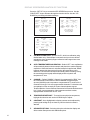
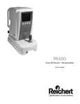
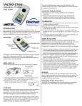
AR7 SERIES
Automatic Refractometer
User’s Guide
1
2
Table of Contents
Preliminary Information
Table of Contents
Warnings and Cautions
3
4
Introduction
Congratulations on your Purchase
Environmental Conditions
Electrical Ratings/Specifications
Instrument Features
5
6
6
7
Instrument Initialization
Set Up
8
Operation
Set Point Calibration
Multi Point Calibration
Sample Reading
Shadow line display
9
10
12
12
Operational Parameters /
Features
Sample Temperature Effects on Readings
13
Automatic Temperature Compensation
14
Temperature coefficient and correction calculations 14
Display Screen/Explanation of Functions
16
Printer Output
18
RS232 Serial Port
18
Serial Control Codes
18
Channel 1 – ICUMSA Brix
19
Channels 2 – 15, User Programmable
19
Key Pad Function, Lock/Unlock
19
Error Messages
20
Maintenance / Specifications
Care and Cleaning
Care of Prism Surface
Preventative Maintenace
21
21
21
Accessories
Extended Precision Calibration Oils
Flow Cell
Funnel Cell
Sample Press
22
22
22
22
Warranty
Warranty Terms
23
3
Warnings and Cautions
CAUTION: IN ORDER TO INSURE THAT CORRECT OPERATION OF THE AR7 SERIES
INSTRUMENT IS MAINTAINED, ANY REPAIR OR SERVICE MUST BE PERFORMED BY
EXPERIENCED PERSONNEL THAT ARE TRAINED BY REICHERT INC.
CAUTION ESDS: THE INTERNAL CIRCUITRY OF THE AR7 SERIES CONTAINS ELECTROSTATIC DISCHARGE SENSITIVE DEVICES (ESDS). SUCH COMPONENTS MAY BE
SENSITIVE TO HIGH VOLTAGES PRODUCED BY STATIC DISCHARGES.
CAUTION: DO NOT USE STRONG SOLVENTS OR STRONG CLEANING SOLUTIONS
ON ANY PART OF THE AR7 SERIES OR DAMAGE TO THE UNIT MAY OCCUR.
WARNING: DO NOT REMOVE OR DEFEAT THE EARTH GROUND CONNECTION ON
THE AR7 SERIES POWER INPUT CONNECTOR OR THE UNIT’S POWER CORD.
DAMAGE TO THE AR7 SERIES INSTRUMENT AND/OR INJURY TO THE OPERATOR
MAY OCCUR.
WARNING: THE AR7 SERIES SHOULD BE USED IN STRICT ACCORDANCE WITH THE
INSTRUCTIONS OUTLINED IN THIS USER’S GUIDE. THE SAFETY OF THE OPERATOR
AND THE PERFORMANCE OF THE INSTRUMENT CANNOT BE GUARANTEED IF
USED IN A MANNER NOT SPECIFIED BY REICHERT INC.
Symbol Information
The following symbols appear on the instrument:
CAUTION: Risk of electric shock
CAUTION: Replace with same type and rating fuse 5x20, 3.15A,
250V Quick Acting.
CAUTION: Indicates that important operating and maintenance
are included in this User’s Guide.
4
INTRODUCTION
Congratulations on your purchase of your new Reichert AR7 SERIES Refractometer.
This manual describes the proper operation and care of this state of the art instrument.
The AR7 SERIES is an automatic, bench top refractometer with digital read out and is
capable of measuring % Solids (Brix), % Solids-TC (Brix-Temperature Compensated,
Sucrose), Refractive Index and Refractive Index-TC. The Peltier controller eliminates the
need for a water bath and has the greatest controllable temperature range set point
available.
An AR7 SERIES has the capability to display data in four languages, English, Spanish,
French and German and can measure refractive index of liquid solutions to a precision of
0.00005 or % solids (Brix) to 0.03. While the instrument has many capabilities it’s
functionality can be expanded considerably by a simple connection to a PC.
Please note that a Refractometer is a high precision optical instrument. It is absolutely
necessary to properly maintain the instrument to obtain the best possible accuracy. This
includes thoroughly cleaning the prism and well after each sample, routinely calibrating
the instrument.
5
ENVIROMENTAL CONDITIONS
•
•
•
•
•
•
Indoor Use only
Temperature Range
10oC – 45oC
Max. relative humidity – 80% for temperatures up 31oC decreasing linearly to
50% (relative humidity at 40oC)
Installation category II (over voltage category)
Pollution degree 2
Altitude up to 2,000 meters
ELECTRICAL RATINGS/SPECIFICATIONS
The Reichert AR7 SERIES incorporates an auto sensing, switching AC power
supply. Never use an adapter, which will interrupt the protective grounding.
•
Caution:
Risk of electrical shock exists if the cover of the
AR7 SERIES is removed. Hazardous voltages will be
exposed, which can cause injury or death. Refer
servicing to a qualified service technician.
•
Supply Voltage:
90 to 264V AC, 47-63 HZ
Input power – 220W PMAX
•
Fuses:
3.15A/250VAC, Quick Acting
•
Illumination:
Long Life LED with 589nm bandpass filter.
•
Range, Channel 1:
0 to 100% Dissolved Solids, Sucrose per
ICUMSA.
1.32000 to 1.60000 nD Refractive index (nD- Sodium D
line refractive index).
•
Readability:
AR700: 0.01% Solids, 0.00001nD
AR70: 0.1% Solids, 0.0001nD
•
Precision:
AR700: +/- 0.01% Solids, +/-0.00001nD.
AR70: +/- 0.1% Solids, +/-0.0001nD.
•
Accuracy:
AR700: +/- 0.03% Solids, +/-0.00005nD.
AR70: +/- 0.1% Solids, +/-0.0001nD.
Typical clear samples, % Solids Temperature
Compensated, as Sucrose.
6
•
Temperature Compensation Range:
Channel 1: 10 to 45o C per ICUMSA tables.
Channels 2-15: user definable.
•
Prism Assembly:
Synthetic Sapphire mechanically sealed to
Stainless Steel Well with Teflon Gasket.
•
Dimensions:
13”W x 16”L x 4 .5” H Weight: 17lbs
(33cm x 40.6cm x 11.5cm)
(7.7kg)
INSTRUMENT FEATURES
1.
Instrument Display – Digitally displays measurement values, operator
instructions and error messages.
Reichert
Automatic Refractometer AR700
Main Ver. 2.01
LSA Ver. 1.57
CPLD Ver. 0005
To calibrate press CALIBRATE
or for set up press SETUP
09:05
2.
Well Temp
20.02
Keypad Controls – All five controls are soft touch membrane keys,
FUNCTION/down, SET UP/up, CALIBRATE/left, MODE/right, and READ. These
keys, other than the Read key , serve a dual purpose as function keys and also
facilitate moving the displayed curser/highlighter when selecting the many
available options through the “SET UP” screen.
SET UP
CALIBRATE
READ
MODE
FUNCTION
3.
Sample Well Cover – The hinged, sample well cover is used
to eliminate or minimize stray light when taking sample readings. It also reduces
the effects of evaporation. Keeping the cover closed when the instrument is not in
use will prevent possible damage and contamination to the sample well and prism
surface. The sample well cover is made of Delrin.
4.
Sample Well – The sample well is made of 416 grade Stainless Steel with a
Sapphire Prism mounted to its center. When a sample is placed on the Sapphire
Prism face, it is important that the sample cover the entire prism surface to attain
an accurate reading. Avoid any air bubbles or particulate matter from settling on
the prism to reduce reading variability.
7
SET UP
A. Unpack instrument from carton. Retain packing material for future
storage/protection/shipping.
B. Place the instrument indoors on a solid surface in an environment where the
temperature is stable. Be sure to keep instrument away from air conditioning
vents or water bath exhaust, drafts can affect the temperature stability.
C. Plug the mating end of the Power Cord into the receptacle located on
the back of the instrument. Plug the opposite end of the Power Cord into an
apropriate receptacle to supply the instrument with power. Never use an adapter,
which will interrupt the protective grounding. Supply Voltage:90 to 264V AC, 47-63
HZ Input power – 220W PMAX
DB9 Connectors
Receptacle
Power Switch
Air Intake
D. Turn the instrument on by activating the power switch located on the
rear panel.
E. Set at the desired operating temperature in the set up screen by pressing SET
UP and scrolling to Temperature Setpoint.
AR700 Setup
Calibration Auto Temperature
Channel/
Routine
Equilibration
Scale
---------------------------------------Set & Span
Off
(ICUMSA)
Temperature Contrast Advanced Exit
Setpoint
Options
---------------------------------------20.00 C
U/D
U
U
L/R to choose option
U/D to change setting
To exit press READ
F. Allow the instrument a warm up period of at least 30 minutes before calibration
or sample reading.
SET POINT CALIBRATION ( Calibration with distilled water only, also
referred to single point calibration )
A. Turn the instrument on by activating the power switch located on the
rear panel.
B. Set at the desired operating temperature in the set up screen by pressing SET
UP and scrolling to Temperature Setpoint.
C. Allow the instrument a warm up period of at least 30 minutes before calibration.
D. Press “CALIBRATE”.
8
E. Follow the displayed instructions to clean prism and press
“CALIBRATE” again.
Clean prism and press
CALIBRATE again to reinitiate
or any other key to cancel
Well Temp
20.01 C
F. Select reading mode by pressing “MODE”, Index-TC, Solids-TC.
Use MODE to select mode
Current mode
INDEX-TC
Add distilled water to sample well.
Allow to equilibrate then
press CALIBRATE.
Well temp.
20.01C
G.
Apply enough distilled water to cover the the prism surface, allow to
temperature equilibrate and press “CALIBRATE”.
Reading and Calibrating
. . .
H. Water calibration complete. Reported value should be 1.33299 +/.00005.
Water calibration complete
1.33299 INDEX-TC
Reference Temperature 20 C
Press SETUP to continue
I.
Press “SET UP” to continue. You are now in the reading screen.
1.33299
20.00 C
3:28 PM
3:32 PM
Channel 1
J.
INDEX-TC
Sucrose (ICUMSA)
Well Temp
24.99 C
Note, it is recommended to clean the air intake on the back of the
instrument and exhaust located on the bottom and perform the single
point distilled water calibration daily, outlined above.
9
SET & SPAN CALIBRATION ( Also known as Multi-point Calibration )
A.
B.
The AR7 SERIES can be calibrated with up to 5 points using 4 standards and
distilled water. Performing a 2 point calibration will provide the required accuracy
needed using distilled water and the supplied high refractive index certified
standard. The reason for the 3, 4 and 5, point calibrations is to precisely calibrate
the instrument to certified standards near the refractive index range where the
measurements are being made. It is extremely important to note that when
performing the multipoint calibration that the lowest valued standard be used first,
proceeding upward to the highest valued standard, the standards should not be
applied randomly. Please see the procedure below to perform the multipoint
calibration.
Raise the sample well cover and inspect the prism and well for
cleanliness. Clean with soapy water, methanol or
Isopropyl alcohol as required, followed by distilled water then dry the prism and
well.
Press the “SET UP” key on the touch panel, the “Set Up” screen will appear.
AR700 Setup
Calibration Auto Temperature
Channel/
Routine
Equilibration
Scale
---------------------------------------Set & Span
Off
(ICUMSA)
Temperature Contrast Advanced Exit
Setpoint
Options
---------------------------------------20.00 C
U/D
U
U
L/R to choose option
U/D to change setting
To exit press READ
C.
D.
E.
F.
Highlight “Calibration Routine” using Left (calibrate), Right (mode), Up (read),
Down (function) keys.
Change the default setting to “Set & Span” using the Up/Down keys.
Press the “READ” key to exit this screen.
Press the “CALIBRATE” key to continue. Follow the displayed instructions to
clean prism and press “CALIBRATE” again.
Clean prism and press
Initiating - Please wait
CALIBRATE again to reinitiate
or any other key to cancel
Well Temp
20.01 C
G.
Follow the on screen instructions to add Distilled Water, allow to temperature
equilibrate and press “CALIBRATE”. Water calibration complete 1.33299, press
“SET UP” to continue.
Multipoint Calibration
Use MODE to select mode
Water calibration complete
1.33299 INDEX-TC
current mode
Index-TC
Reference Temperature 20 C
Add distilled water to sample well.
Allow to equilibrate then
press CALIBRATE
Well temp.
20.01C
10
Press SETUP to continue
H.
Select the next point using the up/dwn keys to highlight the desired point, for
example: 1.51416. Press “READ” to accept. Note that calibration must be in
ascending order of refractive index value. If the calibration standard has a value
other than listed, move the curser to the value that is inbetween two values that
bracket the standards value. For example, if the standard value is 1.52146, move
curser to 1.51416 since 1.52146 is higher than 1.45755 and lower than 1.57230.
Proceed to step I.
SPAN CALIBRATION
Highlight point, select with READ
Repeat with additional points as needed
When complete, select EXIT
Refractive
Index
1.40229
1.45755
1.51416
1.57230
EXIT
Brix
Equivalent
41.24
67.72
88.73
N/H
_
_
_
_
Last
Calibrated
_ _ _ _ _
_ _ _ _ _
_ _ _ _ _
_ _ _ _ _
Use U/D to highlight, READ to select
I.
Adjust the refractive index value which should now be displayed, to the value
listed on the bottle of calibration fluid by pressing “SET UP”. Use the up/dwn/left/
right keys to adjust value. When the value matches press “READ” to accept and
continue. Adjust temperature coefficient value or press “READ” to continue.
Change reference temperature or press “READ” to continue. If the displayed
value matches the value as listed on the bottle of calibration oil, press
“CALIBRATE” to continue.
Calibration Standard
Index
1.51416
Press SETUP to edit
Press CALIBRATE to continue
J.
Add the stated Calibration Standard (ex: 1.51416) to cover prism, allow to
temperature equilibrate and press “CALIBRATE” to continue.
K.
Calibration point complete, press “SET UP” to continue.
Calibration point complete
1.51416 INDEX
Reference Temperature 25 C
Press SETUP to continue
L.
Highlight another calibration point or EXIT and press “READ” to select.
SPAN CALIBRATION
Highlight point, select with READ
Repeat with additional points as needed
When complete, select EXIT
Refractive
Index
1.40229
1.45755
1.51416
1.57230
EXIT
Brix
Equivalent
41.24
67.72
88.73
N/H
_
_
_
_
Last
Calibrated
_ _ _ _ _
_ _ _ _ _
_ _ _ _ _
_ _ _ _ _
Use U/D to highlight, READ to select
11
SAMPLE READING
A.
B.
C.
D.
E.
Clean and dry the prism and well.
Add sample and allow to temperature equilibrate.
Press “READ”.
Note value on display.
Use “MODE” key to switch between the four modes of measurement:
1. INDEX = Refractive index.
2. INDEX-TC = Refractive Index, Temperature Compensated.
3. SOLIDS = Percent Concentration.
4. SOLIDS-TC = Percent Concentration, Temperature Compensated.
The above modes in channel one are for measurement of Sucrose or “Brix”
scale per the International Commission for Uniform Methods. All other channels
are custom scales.
F.
Compare reading to known value. Note any difference in well temperature from
sample reference temperature and adjust refractive index reading mathematically
from the “INDEX” displayed value.
SHADOW LINE DISPLAY
The AR7 SERIES has the ability to graphically display the shadow line enabling
the user to see what the instrument sees. To operate this feature after taking a
reading press and hold the “FUNCTION” key for at least five seconds. When the
key is then released the AR7 SERIES will generate and display a graph of the
Linear Scanned Array output. To exit the shadow line display press “READ”.
Graphic Representation of Detector as Seen on Display
250000
Voltage output of Detector
200000
150000
100000
50000
Pixel Number of Detector
12
3577
3428
3279
3130
2981
2832
2683
2534
2385
2236
2087
1938
1789
1640
1491
1342
1193
1044
895
746
597
448
299
150
1
0
SAMPLE TEMPERATURE EFFECTS ON READINGS
Refractive Index is a physical property of a material. It changes with concentration
and with temperature. As a result, samples need to be at a stable temperature
when read and the reading will be different depending on the sample temperature.
This phenomenon is true for Brix or any other unit of measure that a refractometer
can be programmed to report in since these are calculated from refractive index.
The common methods of managing this are Automatic Temperature
Compensation (ATC) and control of the sample/prism temperature.
Automatic Temperature Compensation
Automatic Temperature Compensation (ATC). Since most uses of refractive index
is in controlling concentration, it is useful to eliminate the temperature effects
when looking at instrument readings. One standard method is to have
programmed channels that calculate the correct reading at 20C for a sample that
is being read at other temperatures. This allows comparing readings to formula or
process specification using 20C values without doing complicated conversions.
Note that custom channels to do temperature compensation are specific to the
material developed for and most likely will provide poor readings if used for a
different material.
The automatic temperature compensation modes built into…
13
AUTOMATIC TEMPERATURE COMPENSATION
Automatic temperature compensation corrects readings over a range of
temperatures. As an example: Samples taken at 10oC – 40oC are corrected to a
reference temperature reading of 20oC. Temperature correction is necessary
because refractive index varies inversely with temperature, as temperature of
sample rises refractive index falls and as sample temperature drops refractive
index will rise. The reason for this is that a sample whose temperature is
changing will report changing refractive index measurements. To speed getting
sample temperature to stabilize, the AR7 SERIES has an internal peltier which
can be set to do this. it is necessary to allow the sample temperature to
equilibrate so that the instrument can properly read the sample.
The automatic temperature compensation modes built into the AR7 SERIES are
based on the temperature coefficients (nD/oC) of sucrose, per the ICUMSA scales.
When readings are taken in INDEX-TC (refractive index-temperature compensated)
mode the coefficients are only valid for sucrose solutions. A typical temperature
coefficient for an aqueous solution is –0.0002/oC and for an organic solution it is
typically
–0.0004/oC. You can calculate the correct temperature coefficient for a specific
solution using the following routine.
Temperature Coefficient Calculations (non-Sucrose samples)
To calculate the temperature coefficient of a sample, the sample must be read in
the Index Mode. Take note of the reported value and the reading temperature. The
sample must then be read at a second temperature. The following calculation may
then be used.
Temperature Coefficient = (nD1 – nD2)/(T1-T2)
where :
nD1 = Refractive Index of sample at temperature 1
nD2 = Refractive Index of sample at temperature 2
T1 = Temperature of Refractive Index reading 1
T2 = Temperature of Refractive Index reading 2
The temperature coefficient is almost always a negative number, in other words,
refractive index increases as temperature decreases and therefore decreases as
temperature rises. Typical temperature coefficients for fluids will be from –0.0001
to –0.0004. Once a temperature coefficient is known, the temperature corrected
refractive index can be calculated from an actual refractive index reading by the
following formula:
14
RITC = ((RT-AT)*TC)+RI
Where:
RITC = Refractive Index Temperature Corrected
RT = Reference Temperature
AT = Actual Temperature as Read on Instrument
TC = Temperature Coefficient Of Sample
RI = Actual Refractive Index As Read On Refractometer
Example: Calibration Verification of an instrument using a known fluid
1. A certified calibration oil is read on an automatic refractometer as having
a refractive index of 1.51519 at 22.48°C.
2. The actual value of the oil as certified by N.I.S.T. is R.I. = 1.51416,
Reference Temperature = 25°C,
Temperature Coefficient = -0.000412 dn/dt.
3. Temperature Differential = Reference Temp. - Actual Reading
Temperature = 25.00 - 22.48 = 2.52
4. Temperature Compensation Factor = Temperature Differential times
Temperature Coefficient = (2.52) x (-0.000412) = -0.00103824
5. -0.00103824 + 1.51519 = 1.51415176. This would be the temperature
corrected refractive index at 25°C In this case, if the value obtained
above differs from the known value of the calibration standard by more
than the accuracy tolerance for the instrument, calibration of the
instrument is necessary.
Sample/prism Temperature Control
Whether using ATC or not, if the temperature of the sample is changing
while reading the reported value will be changing as well. This
phenomenon was used in the previous section in a controlled way to
calculate how the refractive index of a specific material changes with
temperature. Another example is that calibration oils typically change
about .0004 refractive index units/C (look on the label for the specific
value). Controlling temperature during calibrations and when reading
samples is important to accurate and reproducible readings.
To avoid the errors unstable sample temperature can cause, the AR700/
AR70 has an internal peltier which can be set for any temperature from
10C below room temperature to as high as 100C. This is useful when
working with samples that are not at room temperature as the
instrument can be set to measure at the temperature the samples come
into the lab at allowing for temperature equilibrium to be established
quickly.
15
DISPLAY SCREEN/EXPLANATION OF FUNCTIONS
Press the “SET UP” key to access the AR7 SERIES Setup screen. Use the
“RIGHT/LEFT “keys to advance through the function choices. Use the “UP/
DOWN” keys to change the default settings.
AR700 Setup
AR700 Setup
Calibration Auto Temperature
Channel/
Routine
Equilibration
Scale
---------------------------------------Set Pt.
Off
(ICUMSA)
Interval
Delay
Calibration History
Timer
Timer
Display
---------------------------------------Off
Off
U
Temperature Contrast Advanced Exit
Setpoint
Options
---------------------------------------20.00 C
U/D
U
U
Index
Restore
More
Exit
Readability Defaults
Options
---------------------------------------0.00001
U
U
U
L/R to choose option
U/D to change setting
To exit press READ
L/R to choose option
U/D to change setting
To exit press READ
AR700 Setup
Baud
Date
Time
Rate
---------------------------------------115200
Jan 6 2003
18:36
Password
Language
Primary
Exit
Options
---------------------------------------OFF
English
U
U
L/R to choose option
U/D to change setting
To exit press READ
16
A.
CALIBRATION ROUTINE – Default “Set Pt”, which is a calibration using
distilled water only. “Set and Span” uses water and up to 4 user defined
standards to more accurately target a refractive index range where most
readings will be made.
B.
AUTO TEMPERATURE EQUILIBRATION – Default “OFF”. Auto equilibration
will automatically detect when the sample and prism have reached thermal
equilibrium. When this feature is activated a sample is applied and “READ”
has been pressed the instrument will monitor the temperature until it
stabilizes. The instrument will then automatically take the reading. During
the monitoring period a graph will be displayed of the dynamic well
temperature vs. time.
C.
CHANNEL – Default “ICUMSA”. Channel 1 is programmed for “BRIX” from
the International Commission for Uniform Methods of Sugar Analysis
sucrose (ICUMSA) scale, temperature compensated in TC mode to 20 o C.
Channels 2 through 15 are user programmable channels. For directions and
an explanation of the necessity of custom channels please request
Technical Bulletin “Custom Channel Generation for Automatic Refractometer
Line”. Notify your representative of the instruments software version,
displayed when first turned on as Ver. XX.X.
D.
TEMPERATURE SETPOINT – To control the sample/prism temperature,
highlight this selection and use the UP/DWN keys to adjust.
E.
CONTRAST - Once highlighted the display contrast can be adjusted by
pressing and holding the up or down key until the desired contrast is
attained.
F.
ADVANCED OPTIONS – Selecting this option refreshes the display and
offers another Setup screen with additional options.
G.
INTERVAL TIMER – Default “OFF”. Set in HH:MM:SS format, this option
allows the instrument to take readings at definable intervals. Once activated
and defined the AR7 SERIES will continually take readings until a lock out
error occurs such as a lack of sample, or the option is disabled. Interval
Timer is set to “OFF” when the HH:MM:SS is set to 00:00:00 and it is
deselected.
H.
DELAY TIMER – Default “0 SECONDS”. Sets the time a sample is read
once the “READ” or “CALIBRATE” keys are pressed. This parameter is set
in 15 second intervals up to 4 minutes. A count down timer is displayed after
pressing the “READ” or “CALIBRATE” keys when this option is used.
I.
CALIBRATION HISTORY – Pressing the “UP” key will display the previous
512 calibration records. Some parameters extend beyond the limits of the
display, to view these press the Up/Dwn/Lft/Rt keys until the desired
parameter or record is visible.
J.
INDEX READABILITY – Pressing the “UP” or “DOWN” key will change
the index reported value from 0.00001 to 0.0001.
K.
RESTORE DEFAULTS – Pressing the “UP” key will activate another screen
with instructions to press “FUNCTION” to restore defaults or press “SET
UP” to cancel. This allows the user to restore all factory defaults. It will not
erase custom channels or calibration history.
L.
More Options– Press the “SET UP” key to advance to further Set Up
options.
M.
BAUD RATE – Default “115200 bps”. Baud rate options for the RS232 serial
ports are: 57600, 38400, 19200, 9600, 4800 and 2400bps.
N.
DATE – Format is Month/Day/Year. Use the “Up/Dwn/Lft /Rt” keys to
navigate and change the date.
O.
TIME – Can be set to standard 12 hour am/pm or 24 hour military time. Use
the “Up/Dwn/Lft /Rt” keys to navigate and change the time.
P.
PASSWORD – Default “OFF”. Password protection can be used to secure
options once they are set. Turning this option “ON” and pressing “SET UP”
displays the “Enter Password” screen. Use the arrow keys to enter a 3 digit
numerical password. Press “SET UP” to exit. A second screen confirming
your password will appear. Press “READ” to accept the new password or
“SET UP” to cancel. Once the password has been entered the AR7 SERIES
will prompt the user for it each time the Set Up screen is accessed. Keeping
a record of the password in a secure location is recommended.
Q.
LANGUAGE – Default “ ENGLISH”. Language can be changed to Spanish,
French or German by pressing the “UP” or “DOWN” keys to advance through
the choices. Note that the custom channel names and definitions will appear
as entered in the custom channel program.
R.
PRIMARY OPTIONS - Press the “UP” key to return to the initial AR7
SERIES Set Up screen.
S.
EXIT - Pressing the “UP” key returns the AR7 SERIES to the normal
display.
17
PRINTER OUTPUT
The printer output is provided for connecting an external printer through either of two
DB–9 female connectors located on the instrument’s back panel. Communication is by
a 7 bit, parallel bus interface with synchronous operation.
RS232 SERIAL PORT
The AR7 SERIES includes two serial communications ports, DB-9 position female
connectors, located on the instrument’s back panel. Communications settings are: 8
Data Bits, No Parity, 1 Stop Bit. Flow Control Xon/Xoff, Baud Rate settings described
in section 10.0 M, 19200 recommended. Connect to computer with a 9 pin serial
cable, DO NOT USE a “Null Modem Cable” when making the connection.IMPORTANT
NOTE: Connect any required accessories (printer, computer) to the appropriate COM
port on the instrument utilizing the included null modem cables. Do not disconnect
without turning off power to the instrument.
The AR7 SERIES is capable of being controlled from a computer through the Serial
Port interface by using any standard communications program such as “Terminal” or
“Hyperterminal”. Reading output through the serial port may be formatted to retrieve
virtually any data, in any order desired. To format the serial string output, type “help sf”,
brief instructions will appear. To set the serial format, type “sf” followed by the letters
for the output options desired. The default setting is GFA.
SERIAL CONTROL CODES
Many of the advanced functions can only be accessed and set
through the serial port connection. For a complete list of those
codes contact your technical customer service representative.
18
CHANNEL 1 – ICUMSA BRIX
The AR7 SERIES is preprogrammed at the factory with channel 1 to read % Sucrose
or “Brix” scale per the International Commission for Uniform Methods of Sugar Analysis
(ICUMSA). Temperature Corrected (TC) readings in channel 1 are valid for Sucrose
only!
CHANNEL 2 – 15, USER PROGRAMABLE
User programmable channels or custom channels may be programmed using your own
Refractive index, Temperature, % Solids data. Access to the channels is from the Set
Up screen. Custom channels can include definitions for units of measure such as
specific gravity, % protein, g/ml, etc. The units of measure labels are completely
definable and up to 20 characters can be used.
To learn more about Custom channel programming, request “Custom Channel
Generation for Automatic Refractometer Line”. Be sure to inform the technical service
representative of the software version in your instrument, which is displayed as Ver
XX.X when the unit is first turned on.
FUNCTION, LOCK/UNLOCK
During the opening screen when the instrument is first turned on, the keypad can be
locked and unlocked by pressing the “READ”/“CALIBRATE” then “READ”/“MODE”
keys in that order.
19
ERROR MESSAGES
MESSAGE: Refractive index of sample exceeds AR7 SERIES limits.
CAUSE:
Applied sample appears to have a refractive index greater than 1.60000
MESSAGE: Refractive index of sample is below AR7 SERIES limits.
CAUSE:
Applied sample appears to have a refractive index lower than 1.32000
MESSAGE: Refractive index of sample exceeds channel limits.
CAUSE:
Custom channel range does not include refractive index found.
MESSAGE: The index of your sample was higher than expected.
CAUSE:
During calibration, the refractive index of an applied standard was found
to be higher than either the default or user edited index by 0.005 index or
more.
MESSAGE: The index of your sample was lower than expected.
CAUSE:
During calibration, the refractive index of an applied standard was found
to be lower than either the default or user edited index by 0.005 index or
more.
MESSAGE: The index of your sample was more variable than
expected.
CAUSE:
During calibration, usually the result of the prism face not being
sufficiently clean. Clean prism and repeat process.
MESSAGE: The prism is not clean or the cover is open.
CAUSE:
During initialization, the sample well must be clean and dry. If not, this
message is issued.
MESSAGE: The temperature has changed since the last calibration.
Perform a water calibration to maintain accuracy.
CAUSE:
20
Since the last calibration has been performed, the user has changed the
well temperature either from the front panel setup menu or through the
“TEMPERATURE” serial port command by an amount more than the
current tolerance. The tolerance defaults to 3 degrees, but can be
changed to 0 (in which case, the message is not displayed) or some
other value using the serial command “TW”.
CARE AND CLEANING
The Reichert AR7 SERIES is a precision optical instrument. The prism surface and
well should be cleaned immediately after use. The interior components are protected
from dust, spills, and other damage. The stainless steel well and prism assembly is
sealed with a Teflon gasket. All non-optical components can be cleaned with soap and
water or methanol. Using strong solvents such as N, N-Dimethylformamide or N, NNimethylacetamide, cresols, phenols and other tar acids should be avoided,
Tetrahydrofuran or some lacquer thinners and their components can also deteriorate
the prism seal over time or when applied at elevated temperatures. Do not use
acetone, acetone based products or other harsh solvents when cleaning the
instrument’s body or it’s components.
CARE OF PRISM SURFACE
The prism surface should be cleaned immediately after use. While the sapphire prism
has excellent scratch and stain resistance, the use of strong acids or bases should
not be measured with this instrument or used as a cleaning agents. Do not use any
metal or sharp objects to clean or pry loose the prism seal or residue on the sample or
well. The sample should be wiped off with a dry tissue, followed by a thorough
cleaning. Warm water and soap is recommended for removing sugar residue and
methanol for oil based samples followed by a distilled water rinse.
PREVENTATIVE MAINTENANCE
Clean the dust filter located on the back of the instrument on the fan. To accomplish
this carefully pry the inner filter retainer from the mount, there is no need to remove
screws from the mount. Once removed lift the filter foam from where it is positioned
and either blow it clean with light air pressure or wash and rinse it in water. If washed
in water allow the filter to completely dry before reinstalling. Reverse procedure to
install.
21
ACCESSORIES
The Extended Precision Calibration Oils recommended are manufactured by Cargille
Labs, Cedar Grove, NY 07009-1289 USA, Phone 201-239-6633. To our knowledge they
are the only domestic USA source of extended precision standard calibration oils with
six significant figures in index. The characteristics of these oils are:
•
NIST traceable.
•
Stated accuracy at +/-0.00005 nD.
•
Temperature coefficients (TC) are guaranteed at their specified
reference temperatures, usually 20 or 25oC.
•
5 year shelf life.
Catalog No. 13K41330
Catalog No. 13K41340
Catalog No. 13K41350
Catalog No. 13K41360
Catalog No. 13K41370
Calibration Oil, 1.51432
Calibration Oil, 1.40424
Calibration Oil, 1.45755
Calibration Oil, 1.48993
Calibration Oil, 1.57230
NOTE: The values for the above calibration oils are offered as a general
range, and may change somewhat by the supplier of these oils due
to their manufacturing process. A document package accompanies
each bottle stating all of the appropriate values. When using any
new oil for calibration those values should be confirmed.
Catalog No. 13107100 – Flow Cell with Temperature Control
The flow cell allows samples to be pumped to the prism surface.
Typically a peristaltic pump with a flow rate of approximately 10-15
ml./min is used. Use of the flow cell generally increases instrument
precision and eliminates errors due to an unclean prism surface.
Use of the flow cell also allows the user to pre-temperature
equilibrate extremely hot or cold samples. Ports are provided for
circulation of a controlled temperature fluid.
Catalog No. 13107200 – Funnel Flow Cell with Temperature Control
This accessory offers the same benefits as the flow cell
but eliminates the need for a pumping device. 13107200
includes the flow cell, funnel, funnel attachment and tubing.
Catalog No. 13107300 – Sample Press with Temperature Control
The sample press creates an enclosed sample volume by
contacting the top of sample and prism well. It is useful for
decreasing equilibration times of very viscous, hot or cold samples. It is also useful for
measuring volatile liquids such as alcohols. Ports are provided for circulation of a
controlled temperature fluid.
22
WARRANTY TERMS
Please refer to our web site www.reichert.com, Analytical Products, and select
Terms and Conditions of Sale for an explaination of the warranty covering this
Instrument. The warranty period for this product is two years.
23
Reichert Ophthalmic Instruments
Reichert, Inc.
3362 Walden Ave
Depew, NY 14043
USA
Toll Free: 888-849-8955
Phone: 716-686-4500
email: [email protected]
www.reichert.com
Reichert GmbH
Hubertusstrasse 4
D-82229 Seefeld
Germany
Tel: +49-8152-993530
ISO-9001 Certified
24
©2003 Reichert, Inc. Depew NY, USA 13107000-100 Rev. F