1
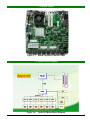
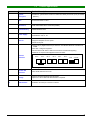
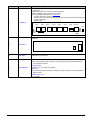
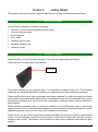
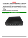
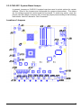
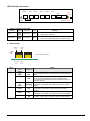
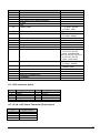
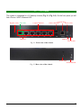
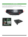
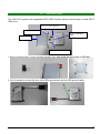
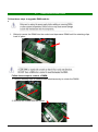
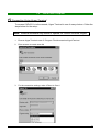
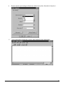
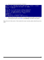
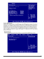
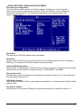
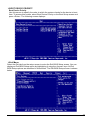
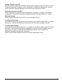
CAD-0211 Series Communication Appliance User′s Manual Revision: 1.1 CE This certificate of conformity of CAD-0211 series with actual required safety standards in accordance with 89/366 ECC-EMC Directive and LVD 73/23 ECC UL This product meets all safety requirements per UL60950 standard. Table of Contents Chapter 1 Introduction ....................................................................................................... 2 1.1 About This Manual .........................................................................................................2 1.2 Manual Organization ....................................................................................................2 1.3 Technical Support Information .......................................................................................2 1.4 Board Layout ................................................................................................................3 1.5 System Block Diagram .................................................................................................3 1.6 Product Specification ....................................................................................................4 Chapter 2 Getting Started .................................................................................................. 6 2.1 Included Hardware .......................................................................................................6 2.2 Before You Begin .........................................................................................................6 2.3 Hardware Configuration Setting ...................................................................................7 2.4 The Chassis ...............................................................................................................12 2.5 Open the Chassis ......................................................................................................13 2.6 Hard drive Install ........................................................................................................14 2.7 Remove and Install DIMM ..........................................................................................16 2.8 Use a Client Computer ...............................................................................................17 Chapter 3 BIOS Setting .................................................................................................. 20 3.1 Main Menu ............................................... ……………………….. CAD-0211 User’s Manual 1 Chapter 1 I ntroduction 1.1 About This Manual This manual contains all required information for setting up and using the CAD-0211 series. CAD-0211 provides the essential platform for delivering optimal performance and functionality in the e ntry c ommunications a ppliance m arket segment. This m anual s hould familiarize you w ith CAD-0211 operations and functions.CAD-0211 series provide up to 6 on-board Ethernet ports to serve c ommunication appl ications l ike F irewall, r equiring 6 E thernet por ts t o c onnect e xternal network (internet), demilitarized zone and internal network. CAD-0211 series overview: INTEL ATOM D525 1.80GHz Memory: Two DDR3 SODIMM slot and up to 8GB Six Gigabit Ethernet interfaces with one Bypass segments Independent management console(RS232) One 2.5” SATA Hard disk 1.2 Manual Organization This m anual describes how t o c onfigure y our CAD-0211 system t o meet v arious o perating requirements. It is divided into three chapters, with each chapter addressing the basic concept and operation of this system. Chapter 1: Introduction. This section describes how this document is organized. It includes brief guidelines and overview to help find necessary information. Chapter 2: Hardware Configuration Setting and Installation. This chapter demonstrated the hardware assembly procedure, including detailed information. It shows the definitions and locations of Jumpers and Connectors that can be used to configure the system. Chapter 3: Operation Information. This section provides illustrations and information on the system architecture and how to optimize its performance. Any updates to this manual, would be posted on the web site: http://www.portwell.com 1.3 Technical Support Information Users may find helpful tips or related information on Portwell's web site: http://www.portwell.com A direct contact to Portwell's technical person is also available. For further support, users may also Portwell’s headquarter in Taipei or local distributors. Taipei Office Phone Number: +886-2-5591-1999 CAD-0211 User’s Manual 2 1.4 Board Layout Figure 1-1 Board Layout of CAD-0211 M/B 1.5 System Block Diagram Figure 1-2 CAD-0211 User’s Manual CAD-0211 Basic Block Diagram 3 1.6 Product Specification Feature Detailed Description 1 System Description 2 CPU 3 CPU Board SB: Intel® 82801HM I/O Controller (ICH8M) 4 System Memory DDR3 800MHz 2Gx2 5 Power Supply 6 Chassis 7 Ethernet interfaces CAD-0211 system series is based on Intel® Atom D525 processors (Luna pier refresh platform) Intel Atom D525 1.8 GHz 12 V AC/DC adapter Certification: CE, UL, 3C Form factor: Desktop chassis. Support nameplate on front panel Hook for DC jack Six PCI-E (x1) Gigabit Ethernet port based on Intel 82583V Ethernet controller from ICH8M. One Gen 1.6 Bypass segments. RJ45 interface with built in LED for ACT/Link and 10/100/1000 signaling. Ethernet I/O sequence and Bypass location as below: Eth-0 Eth-1 Eth-2 Eth-3 Eth-4 Eth-5 USB Console Bypass 0 8 SATA & IDE Interfaces 9 Storage 10 VGA Interface CAD-0211 User’s Manual Eth-0 support PXE (boot on LAN) as default in BIOS One SATA Interfaces on board System is equipped default with fixed HDD Space for 1x2.5” HDD with SATA interface is required. Interface: One 2x5 pin connector on board. 4 Feature Detailed Description 11 RJ45 connector for system console, tab-down, no LED. Pin-definition refers to Appendix-A. Six RJ-45 connector for PCI-E (x1) GbE interfaces Factory Default button. (On board or by cable) LED: Signaling standard refer to Appendix-E - System LED: Power, Data access. - Ethernet LED: For every Ethernet interface there should be LEDs for link status and speed of LAN-ports. - Bypass LED Front Panel Eth-0 Eth-1 Eth-2 Eth-3 Eth-4 Eth-5 USB Console F/D Bypass LED Bypass 0 Power switch DC inlet Dimension: 210x210x40 PWR/DATA LED 12 Rear Panel 13 Dimension Environmental Temperature Range The system shall be able to sustain constant operation at temperatures between 0 and 40 degrees Celsius. Humidity Range At least 10% - 85% Non-Condensing. Vibrations The Platform shall be designed to comply with Office Vibration, and Transportation of GR-63-CORE. Audible Noise Level (< 40 dB) 14 CAD-0211 User’s Manual 5 Chapter 2 Getting Started This section describes how the hardware installation and system settings should be done. 2.1 Included Hardware The following hardware is included in package: CAD-0211 Communication Appliance System Board One null serial port cable AC-DC Adapter SATA cable Hard disk ground cable Hard disk assembly kits Chassis foot pad 2.2 Before You Begin Before starting, you should install foot pad, it can help the chassis has well airflow. There are four foot pads should be installed. Foot pad To pr event d amage t o any s ystem b oard, i t i s i mportant t o h andle i t w ith c are. The following measures are generally sufficient to protect your equipment from static electricity discharge: When handling the board, use a grounded wrist strap designed for static discharge elimination and touches a grounded metal object before removing the board from the antistatic bag. Handle the board by its edges only; do not touch its components, peripheral chips, memory modules or gold contacts. When handling pr ocessor c hips or memory m odules, av oid t ouching t heir pins or g old e dge fingers. R estore t he c ommunications a ppliance s ystem b oard an d p eripherals bac k i nto t he antistatic bag when they are not in use or not installed in the chassis. Some circuitry on the system board can continue operating even though the power is switched off. Under n o c ircumstances s hould t he Lithium bat tery c ell us ed to power t he r eal-time cl ock b e allowed to be s horted. The battery cell may heat up under these conditions and present a burn hazard. CAD-0211 User’s Manual 6 WARNING! 1. "CAUTION: DANGER OF EXPLOSION IF BATTERY IS INCORRECTLY REPLACED. REPLACE ONLY WITH SAME OR EQUIVALENT TYPE RECOMMENDED BY THE MANUFACTURER. DISCARD USED BATTERIES ACCORDING TO THE MANUFACTURER’S INSTRUCTIONS" 2. This guide is for technically qualified personnel who have experience installing and configuring system boards. Disconnect the system board power supply from its power source before you connect/disconnect cables or install/remove any system board components. Failure to do this can result in personnel injury or equipment damage. 3. Avoid short-circuiting the lithium battery; this can cause it to superheat and cause burns if touched. 4. Do not operate the processor without a thermal solution. Damage to the processor can occur in seconds. 5. Do not block air vents. Minimum 1/2-inch clearance required. 2.3 Hardware Configuration Setting 2.3.1 CAD-0211 System CAD-0211 User’s Manual 7 2.3.2 CAD-0211 System Board Jumper In g eneral, j umpers on CAD-0211 system b oard ar e us ed to select options f or certain features. Some of the jumpers are configurable for system enhancement. The others are for testing purpose only and s hould not be altered. To select any option, cover the jumper cap over (Short) or remove (NC) it from the jumper pins according to the following instructions. Here NC stands for “Not Connected”. Location of Jumpers CAD-0211 User’s Manual 8 LED definition on board: Eth-0 Bypass LED Eth-1 Eth-2 Eth-3 Eth-4 Eth-5 Power LEDF/D USB Bypass 0 Console HDD LED 1. Power and Data-access LED Lettering Symbol Function Color PWR Power status Green Data Access Data Access Red Signaling Off – No power, system off. On – Power good, system on. Off – no data access through IDE or SATA channel On – data is in transition through IDE or SATA channel 2. Ethernet LED ACT/Link LED Speed LED Bypass LED Copper Ethernet Interface ACT/Link LED Speed LED Label Status Color ACT/LINK Green Or Others Indication On Off Green Or Others Flashing Yellow On Green On SPEED Off CAD-0211 User’s Manual 1. The Ethernet port is receiving power. 2. Good linkage between the Ethernet port and its supporting hub. 1. The adapter and switch are not receiving power. 2. No connection between both ends of network cable. 3. The drivers of Ethernet have not been loaded or does not function correctly. The adapter is sending or receiving network data. The frequency of the flashes varies with the amount of network traffic. ACT/LNK LED must on then this LED show the operating at 1000 Mbps. If ACT/LINK is off and this function will be disable. ACT/LNK LED must on then this LED show the operating at 100 Mbps. If ACT/LINK is off and this function will be disable. ACT/LNK LED must on then this LED show the operating at 10 Mbps. If ACT/LINK is off and this function will be disable. 9 Connector J1 J2 J3,J4 J5 J6 J7 J8 Function DC Power Jack (12V) 12V power switch DDR3 800 DIMM Slot CPU Smart Fan Power connector 80 port PS/2 CMOS Clear J11 J12 J13 J14 J15 J16,J17 System WDT J19 Bypass LED J20~J26 J27 J28 J29 *1-2 short : enable, VGA connector System Smart Fan Power connector Sata power USB pin header SATA connector Open mode jumper J18 *1-2 short : normal, 2-3 short : clear NMI Bypass function J9 J10 Remark RJ45 connector Console Port HDD LED +Power LED F/D Button 2-3 short: disable J16(1-2,3-4,5-6,7-8),J17(12,3-4,5-6,7-8,9-10) short : normal mode J16(1-2,3-4,5-6,7-8),J17(12,3-4,5-6,7-8,9-10) open : open mode 1-2 short : enable, 2-3 open : disable Bypass: red Normal: green J11: VGA connector define Pin 1 3 5 7 9 Signal Name RED GREEN BLUE HSYNC VSYNC Pin 2 4 6 8 10 Signal Name DDCCLK Ground DDCDATA Ground N/C J13: +5V & +12V Power Connector (Only Output) Pin 1 2 3 4 Signal Name VDD_12V GND GND VDD_5V CAD-0211 User’s Manual 10 Factory Default : D-TYPE FLIP-FLOPS Pin Signal Name PRE# Factory Default Button CLR# Q ICH8_GPIO3 ICH8_GPIO4 System Reset : Or Gate Pin Signal Name B Y SIO Watch dog timer System Reset A CAD-0211 User’s Manual ICH8_GPIO33 11 2.4 The Chassis The system is integrated in a 1U desktop chassis (Fig. 2-1, Fig. 2-2). On the front panel you will find a Power / HDD / Ethernet LED. Bypass LED PXE Port Copper Ethernet Console Port USB Connector Power LED Bypass 0 HDD LED F/D Switch Fig. 2-1 Front view of the chassis Power Inlet Power Switch Fig. 2-2 Rear view of the chassis CAD-0211 User’s Manual 12 2.5 Open the Chassis If you want to install or change I/O devices, please open top cover of chassis. Loosen the 4 screws of bottom side of the chassis; two are on the right/left side and two are on bottom side, then to remove the top cover Top cover screw CAD-0211 User’s Manual 13 2.6 Hard drive Install The CAD-0211 system has supported SATA HDD function; please follow steps to install SATA HDD drive. Screws to secure HDD bay HDD ground cable HDD bay damping plate HDD bay Screws for secure HDD 1. Before install hard drive, please assembly damping plate, and Install damping plate to HDD bay 2. Use 4 screws to secure the drive into HDD bay and also secure HDD ground cable CAD-0211 User’s Manual 14 3. Fix HDD bay and connect SATA cable to hard drive and board connector 4. Connect HDD ground cable to M/B CAD-0211 User’s Manual 15 2.7 Remove and Install DIMM Follow these steps to upgrade RAM module: 1. Obliquity inserts the DIMM into the socket and depresses DIMM until the retaining clips back in place Follow these steps to remove a DIMM: 1. Pull the retaining clips of DIMM socket simultaneously to unlock the DIMM 2. Remove the DIMM from the socket CAD-0211 User’s Manual 16 2.8 Use a Client Computer Connection Using Hyper Terminal To access CAD-0211 via the console, Hyper Terminal is one of many choices. Follow the steps below for the setup: Note: Terminal software may need to update for correct console output. 1. Execute HyperTerminal under C:\Program Files\Accessories\HyperTerminal 2. Enter a name to create new dial 3. For the connection settings, make it Direct to Com1. CAD-0211 User’s Manual 17 4. Please make the port settings to Baud rate 19200, Parity None, Data bits 8, Stop bits 1 5. Turn on the power of CAD-0211 system, after following screen was shown: CAD-0211 User’s Manual 18 6. User can see the boot up information of CAD-0211 7. When message “Hit <DEL> if user want to run Setup” appear during POST, after turning on or rebooting the computer, press <Tab> key immediately to enter BIOS setup program. This is the end of this section. If the terminal did not port correctly, please check the previous steps. CAD-0211 User’s Manual 19 Chapter 3 BIOS Setting Power on the system, press the <Del> to run BIOS setup (remote mode is <Tab>). After you press the <Delete> key, the main BIOS setup menu displays. You can access the other setup screens from the main BIOS setup menu, such as the Chipset and Power menus. The BIOS setup/utility uses a key-based navigation system called hot keys. Most of the BIOS setup utility hot keys can be used at any time during the setup navigation process. These keys include <F1>, <F10>, <Enter>, <ESC>, <Arrow> keys, and so on. Control Keys Key ↑↓Up /Down Left/Right +Plus/ Minus Tab CAD-0211 User’s Manual Function The Up and Down <Arrow> keys allow you to select a setup item or sub-screen. The Left and Right <Arrow> keys allow you to select a setup screen. For example: Main screen, Advanced screen, Chipset screen, and so on. The Plus and Minus <Arrow> keys allow you to change the field value of a particular setup item. For example: Date and Time. The <Tab> key allows you to select setup fields. 20 CAD-0211 User’s Manual 21 Main Menu When you first enter the Setup Utility, you will enter the Main setup screen. You can always return to the Main setup screen by selecting the Main tab. There are two Main Setup options. They are described in this section. In console mode: Press “TAB” key can into BISO setup man menu Press “B” key can popup device boot menu Press “L” key can boot from network System Date / Time Use this option to change the system time and date. Highlight System Time or System Date using the <Arrow> keys. Enter new values through the keyboard. Press the <Tab> key or the <Arrow> keys to move between fields. The date must be entered in MM/DD/YY format. The time is entered in HH:MM:SS format. CAD-0211 User’s Manual 22 Advanced BIOS Setup Select the Advanced tab from the setup screen to enter the Advanced BIOS Setup screen. You can select any of the items in the left frame of the screen, such as SuperIO Configuration, to go to the sub menu for that item. You can display an Advanced BIOS Setup option by highlighting it using the <Arrow> keys. All Advanced BIOS Setup options are described in this section. The Advanced BIOS Setup screen is shown below. The sub menus are described on the following pages. CPU Configuration You can use this screen to select options for the CPU Configuration. Use the up and down <Arrow> keys to select an item. Use the <Plus> and <Minus> keys to change the value of the selected option. Note: The CPU Configuration setup screen varies depending on the installed processor. CAD-0211 User’s Manual 23 IDE Configuration Setup From the IDE Configuration screen, press <Enter> to access the sub menu. Use the up and down <Arrow> keys to select an item. The settings are described on the following pages. SUPER IO CONFIGURATION You can use this screen to select options for the Super I/O settings. Use the up and down <Arrow> keys to select an item. Use the <Plus> and <Minus> keys to change the value of the selected option. The settings are described on the following pages. The screen is shown below. CAD-0211 User’s Manual 24 REMOTE ACCESS CONFIGURATION You can use this screen to select options for the Remote Access Configuration. Use the up and down <Arrow> keys to select an item. Use the <Plus> and <Minus> keys to change the value of the selected option. The settings are described on the following pages. The screen is shown below. Remote Access You can disable or enable the BIOS remote access feature here. Serial Port Number Select the serial port you want to use for console redirection. You can set the value for this option to either COM1 or COM2. Serial Port Mode Select the baud rate you want the serial port to use for console redirection. USB Configuration You can use this screen to select options for the USB Configuration. Use the up and down <Arrow> keys to select an item. Use the <Plus> and <Minus> keys to change the value of the selected option. The settings are described on the following pages. The screen is shown below. CAD-0211 User’s Manual 25 Legacy USB Support Legacy USB Support refers to the USB mouse and USB keyboard support. Normally if this option is not enabled, any attached USB mouse or USB keyboard will not become available until a USB compatible operating system is fully booted with all USB drivers loaded. When this option is enabled, any attached USB mouse or USB keyboard can control the system even when there is no USB drivers loaded on the system. Set this value to enable or disable the Legacy USB Support. The Optimal and Fail-Safe default setting is Disabled. Boot Settings Select the Boot tab from the setup screen to enter the Boot BIOS Setup screen. CAD-0211 User’s Manual 26 BOOT SETTINGS CONFIGURATION SCREEN Boot Settings Configuration Use this screen to select options for the Boot Settings Configuration. Use the up and down <Arrow> keys to select an item. Use the <Plus> and <Minus> keys to change the value of the selected option. The settings are described on the following pages. The screen is shown below. Quick Boot The Optimal and Fail-Safe default setting is Enabled. Quiet Boot Set this value to allow the boot up screen options to be modified between POST messages or OEM logo. The Optimal and Fail-Safe default setting is Disabled Add-On ROM Display Mode Set this option to display add-on ROM (read-only memory) messages. The Optimal and Fail-Safe default setting is Force BIOS. An example of this is a SCSI BIOS or VGA BIOS. Boot up Num-Lock Set this value to allow the Number Lock setting to be modified during boot up. The Optimal and Fail-Safe default setting is On. PS/2 Mouse Support Set this value to allow the PS/2 mouse support to be adjusted. The Optimal and Fail-Safe default setting is Auto Interrupt 19 Capture Set this value to allow option ROMs such as network controllers to trap BIOS interrupt 19. CAD-0211 User’s Manual 27 BOOT DEVICE PRIORITY Boot Device Priority Use this screen to specify the order in which the system checks for the device to boot from. To access this screen, select Boot Device Priority on the Boot Setup screen and press <Enter>. The following screen displays: Exit Menu Select the Exit tab from the setup screen to enter the Exit BIOS Setup screen. You can display an Exit BIOS Setup option by highlighting it using the <Arrow> keys. All Exit BIOS Setup options are described in this section. The Exit BIOS Setup screen is shown below. CAD-0211 User’s Manual 28 Saving Changes and Exit When you have completed the system configuration changes, select this option to leave Setup and reboot the computer so the new system configuration parameters can take effect. Select Exit Saving Changes from the Exit menu and press <Enter>. Discarding Changes and Exit Select this option to quit Setup without making any permanent changes to the system configuration. Select Exit Discarding Changes from the Exit menu and press <Enter>. Discard Changes Select Discard Changes from the Exit menu and press <Enter>. Load Optimal Defaults Automatically sets all Setup options to a complete set of default settings when you select this option. Select Load Optimal Defaults from the Exit menu and press <Enter>. Load Fail-Safe Defaults Automatically sets all Setup options to a complete set of default settings when you select this option. The Fail-Safe settings are designed for maximum system stability, but not maximum performance. Select the Fail-Safe Setup options if your computer is experiencing system configuration problems. Select Load Fail-Safe Defaults from the Exit menu and press <Enter>. CAD-0211 User’s Manual 29