1
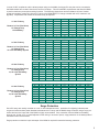
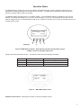
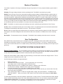
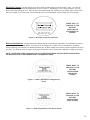
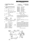
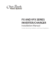
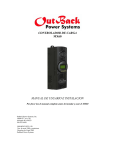
MX60
PV MPPT Charge Controller
I N S TA L L AT I O N A N D U S E R ’ S M A N U A L
Please read this entire manual prior to installing and using the MX60.
OutBack Power Systems, Inc 19009 62nd Ave NE Arlington WA 98223
360-435-6030
900-0028-1 Rev.-
Introduction
Your OutBack PV MX60 Maximum Power Point Tracking (MPPT) charge controller enables your PV system to achieve its
highest possible performance.
Rated for up to 60 amps of DC output current, your MX60 can be used with battery systems from 12 to 60 vdc with PV
open circuit voltage as high as 125 vdc. The MX60's setpoints are fully adjustable to allow use with virtually any battery
type, chemistry and charging profile.
Your MX60 allows you to use a higher output voltage PV array with a lower voltage battery - such as charging a 24 vdc
battery with a 48 vdc PV array. This reduces wire size and power loss from the PV array to the battery/inverter location
and can maximize the performance of your PV system.
Your MX60 comes standard with an easy to use and understand display of the PV system’s performance. The four line,
80 character, backlit LCD display is also used for programming and monitoring of the system’s operation.
Your MX60 can also be connected to the OutBack MATE system controller and display to allow monitoring of up to eight
MX60 controllers from a distant location - up to 300 feet away. The MATE also includes an opto-isolated RS232 port for
connection to a PC computer for data logging and system monitoring.
A built-in Auxiliary Output Control System can be used to control a secondary control circuit, relay or contactor. It can be
used to control a diversion load, low battery disconnect, load management power shedding, or other functions.
Important Safety Instructions
A. SAVE THESE INSTRUCTIONS - This manual contains important instructions for the MX60 PV MPPT Charge
Controller that shall be followed during installation and maintenance of the charge controller.
B. Torque the terminal block and ground terminals to 30 inch pounds / 4Nm
C. Use a minimum of 6AWG copper conductors only suitable for a minimum of 75 degrees C. The terminal block will
accept up to 4 AWG conductors. The ground terminal will accept up to 2 AWG conductors.
D. This symbol is used to identify chassis ground.
E. This charge controller is intended to charge lead acid battery systems, sealed or vented with nominal voltages of 12,
24, 32, 36, 48, 54 or 60 volts DC. For other battery chemistries, contact the battery manufacturer for specific charge
control settings and methodology.
F. The MX60 PV MMPT Charge Controller is for indoor use only.
2
Installation
The MX60 is designed to be mounted in a variety of ways. One of the more common methods of mounting is on an
OutBack charge controller bracket (CCB), attached to an OutBack PSDC enclosure. Each MX60 comes with three #10
stainless steel sheet metal screws for this purpose. Under the wiring compartment cover are holes through the mounting
feet for attachment to the CCB . There is also a mounting tab at the top of the MX60. When mounted to the OutBack
CCB the left side knockout will line up with knockouts in the PSDC. A standard ¾" or 1" plastic snap-in bushing will offer
protection from chafing between the two boxes. Note that there are two placement options on the CCB that can be used
to match with knockouts in the PSDC. Mounting holes and knockouts are compatible with C40 controllers to help set an
industry standard. Two MX60 controllers may be installed on the CCB. Note the placement shown in Figure 1.
Figure 1 Two MX60 Charge Controllers mounted on a CCB
3
Mounting the MX60
Up to three MX60's can also be mounted on top of a PSDC. Below is a view from the top of the PSDC enclosure. The
MX60 will mount using 1" TSC threaded nipples to the 2" spacings. One knockout is provided and one pilot hole for the
second hole. The 1.83" spacings are for two Solar Boost controllers.
Figure 2 MX60 mounting options on the top of an OutBack PSDC, DC Disconnect Enclosure
Two 1" TSC threaded nipples may be used to secure the controller to the PSDC top for many installations. All of the
wires will fit through one knockout so the second can be used as a means of attachment. If two nipples are used for
wiring, then drill and through bolt to the PSDC top using a couple #10 (5mm) screws, lockwashers and nuts. Plastic
snap in bushings may be substituted for metal nipples if the two boxes are screwed together. The use of a 7/8 inch
spacer behind the MX60 when installed in either of the two rear positions will allow the mounting foot holes to be used to
secure the chassis back to the wall.
When mounting the MX in a confined space, be careful not to block the fan opening or the air inlet holes towards the
bottom of the chassis on either side. One side may be blocked, but not both. Although this will not damage the controller,
it will decrease efficiency and may cause it to shut off due to an overtemperature error..
Wire and Disconnect Sizing
When wiring the MX60 note that there is a current limit on the output at 60 amps and that the unit is listed to operate
continuously at 60 amps. There is no 80% derating as required by the NEC for fuses, conductors, and most circuit
breakers.
The MX60 is a buck type converter and does not boost the output current when the PV array peak power point voltage
is below the battery voltage as may happen on hot days in 24VDC PV and a 24VDC battery system or a 48VDC PV and
a 48VDC battery system.
This unit can supply up to 60 amps output depending on the nominal PV array voltage and the nominal battery voltage.
The output is current limited to 60 amps. To meet minimum NEC requirements, the output conductor should have an
ampacity after any temperature and conduit fill corrections of 1.25 x 60=75 amps (NEC 310.15, 690.8,9). This would
normally indicate that the output conductors would be 4 AWG, but a larger size may be required if there are temperature
and/or conduit fill corrections required. With an output conductor rated at 75 amps (1.25 time continuous output current),
a circuit breaker ratted for continous 100% duty at 60 amps (continuous output) like the Outback OBDC-60 breaker may
be used to provide the code-required output circuit overcurrent protection and disconnect.
The PV array output connected to the MX60 input may be as high 60 amps, but at this current level, there is no current
boosting or maximum power-point tracking due to the 60-amp output current limit. Additionally, the input current may
exceed 60 amps on bright sunny days and any excess power would be lost. The size and ampacity of the input conductors must be selected to handle 1.56 times the short-circuit current of the PV array. Any disconnect or circuit breaker
connected to the input conductors must also be rated at 1.56 times the short-circuit current for the PV array unless it the
breaker rated for 100% duty in its enclosure. If that is the case, the circuit breaker may be rated at 1.25 times the PV
array short-circuit current.
4
In terms of NEC compliance and the 60-amp output rating on the MX60, the largest PV array that can be connected to
the MX60 should have a rated short-circuit current of 48 amps. This will meet NEC requirements and allow the MX60
to perform maximum power-point tracking functions. The following charts show maximum distance in feet of various
guage two conductor copper wire from the PV array to the MX60 MPPT PV charge controller with a 2% maximum voltage drop. Temperature and conduit fill corrections may be required.
12 Volt PV Array
Distance in Feet (Two Wires)
2% Voltage Drop
12 Volt Battery
24 Volt PV Array
Distance in Feet (Two Wires)
2% Voltage Drop
12 or 24 Volt Battery System
48 Volt PV Array
Distance in Feet (Two Wires)
2% Voltage Drop
12, 24 or 48 Volt Battery
System
60 Volt PV Array
Distance in Feet (Two Wires)
2% Voltage Drop
12, 24 or 48 Volt Battery
System
Amps
8
10
15
20
30
40
50
60
#8
#6
#4
#2
#1/0
#2/0
#4/0
22
18
12
9
6
4
3
3
35
28
19
14
9.
7
5
4
57
45
30
22
15
11
9
7
90
72
48
36
24
18
14
12
145
115
76
57
38
29
23
19
180
145
96
72
48
36
29
24
290
230
150
116
77
56
46
38.
Amps
8
10
15
20
30
40
50
60
#8
#6
#4
#2
#1/0
#2/0
#4/0
45
36
24
18
12
9
7
6
71
57
38
29
19
14
11
9
114
91
60
45
30
23
18
15
180
145
96
72
48
36
29
24
290
230
153
115
77
58
46
38
360
290
192
145
97
72
58
48
580
460
300
232
154
112
86
77
Amps
8
10
15
20
30
40
50
60
#8
#6
#4
#2
#1/0
#2/0
#4/0
90
72
48
36
24
18
14
12
142
114
76
58
38
28
22
19
228
182
120
90
60
46
36
30
360
290
192
144
96
72
58
48
580
460
306
230
154
116
92
77
720
580
384
290
194
144
116
97
1160
920
600
464
308
224
172
154
Amps
8
10
15
20
30
40
50
60
#8
#6
#4
#2
#1/0
#2/0
#4/0
112
90
60
45
30
22.5
17.5
15
177
142
95
72
47
35
27
23
285
227
150
112.
75
57
45
37
450
362
240
180
120
90
72
60
725
575
382
287
192
145
115
96
900
725
480
362
230
180
145
121
1450
1150
750
580
385
280
215
192
Surge Protection
Since PV Arrays are usually mounted on a roof or other elevated structure, protection from lightning induced power
surges and other transient power disturbances between the PV array and the MX60 charge controller using a surge protection device on the input side of the MX60 is highly recommended. If the connection from the MX60 to the battery
string is over 15 feet or if it is routed adjacent to other wiring or sources of power, surge protection on the batteryt side of
the MX60 is also recommended.
Surge protection on both the input and output of the MX60 is required for extended warranty protection.
5
Connections
The wiring terminals for the MX60 charge controller are shown in Figure 3. There is no required connection sequence.
Figure 3 MX60 wiring area and wiring terminals
The large terminal block in the center is for PV+, PV-, BAT- and BAT+. The aluminum terminal on the right side of the
chassis is the equipment ground. The equipment-grounding terminal can mounted on the outside of the enclosure if
desired, although normally the equipment-grounding conductors will be routed in the same conduits with the input and
output circuit conductors. If the equipment grounding terminal is moved to the outside, make sure that the star washer is
re-used. This washer is used to penetrate through the paint, thus grounding the chassis. NEC requires the use of an
array disconnect and a battery disconnect. The MX60 can use a 60 amp 125VDC breaker such as the OBDC60 breaker.
All of the large terminals should be torqued to 30 inch pounds. The PV /BAT terminal will accept up to 4AWG wire. The
equipment ground takes up to 2AWG.
An optional MX60 remote battery temperature sensor is connected to the right of the BAT+ terminal in a RJ11 marked "
Battery Temp". This sensor is mounted on one of the batteries using the double back tape included. Battery manufacturers recommended charging voltages are based on 25oC / 77oF. Batteries cannot be properly charged without a remote
sensor unless the batteries remain at 70oF. The OutBack Temp sensor will automatically change voltage up or down
depending on the sensor’s temperature. This is especially important in very hot or very cold climates. This is a highly
recommended option.
To the right of the temp sense jack is a small two position terminal block marked AUX. The terminals are marked Ground
and +12V. The terminals are programmable to accomplish an assortment of functions such as load diversion or alarms.
The output current available on this terminal block is 200 milliamps. This is enough to power the coil of a relay or for a
small piezo buzzer or LED indicator. The AUX output is protected internally by an automatic resetting poly fuse.
To the left of the PV+ terminal is an RJ45 jack marked MATE. The MATE is the OutBack remote display panel. Most of
the status that is available on the MX60 is available at the Mate as well. Some triggered events can be accomplished at
the MATE also.
Figure 4 The MATE System Management and Remote Control
CAUTION: It is normal for the PV input voltage input voltage to rise up to a level close to the battery voltage when the
battery is connected and the PV array is disconnected. This is a normal condition for the MX60. The MX60 is designed
for PV input only and will not function properly with other power sources or combinations of PV and other power sources
or in parallel with other charge controllers.
6
Operation Status
The MX60 Charge Controller has a 4 line, 80 character LCD display and four “soft key” buttons to allow the user to
adjust battery charging parameters and access other information. The MX60 has an adjustment screen lockout that
requires an access code to make any changes.
The MX60 is factory preconfigured for a 12V battery system. All of the default settings are multiples of 12V nominal
settings. The default bulk setting is for 14.3 VDC. The float setting is 13.15 VDC. The controller will process up to 60
amps of output current. It is recommended to install up to a maximum of 48 amps of PV to give the controller some room
to boost the PV current.
OutBack
24V
Power
MX60
Soft keys
1
Systems
2
3
4
Figure 5 MX60 Start-up Screen. Note that the selected nominal battery system
voltage is shown in the upper right corner.
Figure 6 shows the Main Status Screen. This default screen shows the following information:
Top Line
Second Line
Third Line
Fourth Line
PV array voltage
Current in from PV array
Instantaneous output watts
Daily KWH produced
Battery system voltage
Current out to battery system
Aux relay status
Mode of operation
PV 50
Bat 25 Vdc
In 20
Out 40 Amps
Watts 1000
Aux off
KWH 02.5
MPPT
Figure 6
MX60 Main Status Screen
Software Version Check: Hold button No.2 down to show the software version.
7
Modes of Operation
The modes of operation will change occasionally during the day based on PV array output and battery system state of
charge.
Sleeping: PV output voltage is below minimum operating levels. The MX60 is not producing any power.
Wakeup: As the PV open circuit (Voc) rises above the battery system voltage, the MX60 prepares to deliver power to
the batteries. During this 5 second period the MX is calculating PWM duty cycles, turning on power supply voltages in
the proper sequences, making internal calibrations and performing an initial PV IV (Amps / Volts) sweep. At the end of
the wake up period the MX60 closes its relays and produces power. At dusk and dawn this will happen many times until
there is not enough power from the PV array to keep going. Upon closing the relays, if it is determined that it is just still
too early (or too late), the MX will display Lolite for a few seconds and then display Snoozing for 5 minutes. Think of it
as if the MX has just hit the snooze button on an alarm clock and is taking a short nap.
MPPT: The MX60 is in maximum power point tracking mode and is maximizing the performance of the PV array.
Voc Err: This is an indication that the open circuit voltage of the PV is significantly above the last stored measurement.
The MX60 will automatically restart after one minute. No intervention is required.
Re-cal: There are certain abnormal conditions that can confuse the current measuring method in the MX. When and if
this happens, the artificial intelligence built into the MX will take a few seconds to re-calibrate the current monitoring
circuit.
Bat Tmp Err: The temperature sensor is damaged. The MX60 will stop operating unless the sensor ia removed.
User Configuration
Many MX60 factory set parameters can be changed by the user. Pressing the button under "NEXT" selects which
parameter you are going to change. The one that is presently selected will have a * in front of it. Pressing the button
under “EXIT” will store the value in non-volatile memory. Disconnecting the MX60 from the battery will not require re-programming.
SET BATTERY SYSTEM VOLTAGE FIRST !
Battery System Voltage: The nominal battery system voltage can be changed from the default of a 12 volt battery
to match your particular battery system. Only the battery system voltage needs to be set, the MX60 automatically senses the nominal PV array voltage and finds the maximum power point during operation.
Setting the nominal battery system voltage will require entering an access code to access the change screens. The following access code is required for this unit: 141
Use the following procedure to change parameters:
1.
2.
3.
4.
5.
6.
7.
8.
Battery switched off
Hold down push buttons #1 and #3.
(Left to right buttons are: #1 #2 #3 #4)
Turn battery switch on while holding buttons #1 and #3 down.
Release buttons as soon as “OutBack Power Systems” appears on the LCD screen.
You will see the message " MX60 has been reset / pick a configuration"
It will ask what mode to run. Push button #1 (MPPT) then push “NEXT”.
You will now be at the password screen. Push “DOWN” until the number reaches your access code. Press the
button below the word “ENTER”.
Hit the button below “NEXT” to select the nominal battery voltage, then press “ENTER”. The MX60 will ask
“ARE YOU SURE?”. When you push the “YES” button, the unit will reset and then displays the Main Status
Screen.
To reset these parameters to the factory defaults, repeat steps 1 through 4 above. The actual Absorb and Float voltages
will be modified automatically with the use of the external temperature sensor. You can view the compensated voltages
in Miscellaneous Screen No 3. The amount of compensation the temp sensor provides is 30 millivolts per degree
Celsius for a 12 volt system. This compensation is multiplied by 2 for a 24 volt system, etc.
8
Charger Parameters The charger parameters that are automatically adjusted when the nominal battery system
voltage is set can be modified. The default ABSORB Volts and FLOAT Volts setpoints are based on average lead acid
battery systems. The default charger current limit is 60 Amps. If the manufacturer of the batteries you are using recommends different ABSORB Volts and FLOAT Volts setpoints you can change the default setpoints using the Charger SetUp Screen shown in Figure 7. If your system requires current limiting other than 60 Amps due to breaker or wire rating
you can change the current limit setpoint using this screen.
Enter the Charger Set-Up Screen from the Main Status Screen (Figure 6) by pushing button #1 (Button under KWh).
Pressing "NEXT" selects which parameter you are going to increase or decrease. The one that is presently selected will
have a * in front of it. You may need to re-enter your access code for this set-up screen.
PRESS BUTTON #1
ON MAIN STATUS
SCREEN TO ENTER
CHARGER SET-UP
SCREEN
PRESS “EXIT” TO
CONTINUE TO THE
AUXILIARY RELAY
SCREEN
Figure 7 Charger Set-up Screen
Auxiliary Output The user can set the function for this secondary control circuit. Pressing "NEXT" selects which
parameter you are going to increase or decrease. The choices are: Manual, Disabled, Diversion, Low Battery
Disconnect, and External. The terminal marked "Aux" supplies a 12 VDC at 200 milliamp max output. This output can
be used to power the coil of a contactor or relay. It can also directly drive a small piezo buzzer or a small 12V LED indicator.
Manual Mode: You can turn on and off the AUX output manually from the MX60 keypad.
Disabled: The AUX output terminals have no output.
Diversion Mode: Used when a wind or hydro generator is connected directly to the batteries and excess power needs
to be diverted when the battery is full. This mode can also be used to turn on a fan for battery box ventilation. The AUX
output terminal will become active (produce 12VDC) when the battery voltage reaches ABSORB or FLOAT voltage
minus an adjustable value. The value is adjustable in tenths of a volt from 0.1 to 5.0 volts. There is a fixed minimum time
period of 15 seconds for the AUX output terminals to be energized.
Low Battery Disconnect Mode / Load Management Power Shedding: The Aux output terminals are energize when
the battery voltage drops below a low battery set point for a time delay period.The time period is adjustable from 0 - 254
minutes.
Remote Control: A MATE can control the operation of the Aux output in the MX controller. Only one MX or FX device's
Aux control output can be controlled by the MATE.
PRESS “EXIT” TO
CONTINUE TO THE
BACKLIGHT
CONTROL SCREEN
Figure 8 Auxiliary Output Set-up Screen
9
Backlight Control: The back lighting of the LCD screen and the buttons consumes about ¾ watt. The user can
control backlight options using the setup screen shown in Figure 9. Depending on your energy production, you may
elect to leave the lighting off or on. There is also a third option called Auto. Tapping any key quickly while in Auto mode
will turn the lights on for 30 seconds. This first key tap to turn on the backlight will not change any of the settings.
PRESS “EXIT” TO
CONTINUE TO THE
BATTERY
EQUALIZATION
VOLTAGE SET-UP
SCREEN
Figure 9 Backlight Control Set-up Screen
Battery Equalization: Flooded electrolyte batteries should occasionally be subjected to an equalization process to
convert sulfation from the lead plates. This process can be dangerous, so make sure you understand it completely
before equalizing your batteries! The default EQ setting are: equalize voltage set to absorb volts and equalize time set to
one hour. The screens shown in Figures 10 through 12 allows the user to change the equalization voltage and process.
NOTE: VALVE REGULATED LEAD ACID (VLRA) OR SEALED BATTERIES SHOULD NEVER BE EQUALIZED
UNLESS SPECIFICALLY RECOMMENDED BY THE MANUFACTURER.
PRESS “NEXT” TO
CONTINUE TO THE
BATTERY
EQUALIZATION
TIME SET-UP
SCREEN
Figure 10 Battery Equalization Voltage Set-up
Screen
PRESS “NEXT” TO
CONTINUE TO THE
BATTERY
EQUALIZATION
START SCREEN
Figure 11 Battery Equalization Time Set-up Screen
10
USER CONFIGURATION
COMPLETE
PRESS “STOP” TO
RETURN TO THE MAIN
STATUS SCREEN
OR
Figure 12 Battery Equalization Start Screen
PRESS “EXIT” TO
CONTINUE TO THE
MISCELLANEOUS
SCREEN NO. 1
The Battery equalization process must be started manually. The screen shown in Figure 12 is used to start the
equalization process. The EQ process is automatically terminated once the EQ time period has occurred. Pressing
“Stop” will over-ride the timed EQ charge.
Miscellaneous Screens: The screens shown in Figures 13, 14 and 15 are primarily for engineers, technicians, and
customer service personnel who need to access technical information. The following is a brief description of the contents
of these screens:
PRESS “NEXT” TO
CONTINUE TO THE
MISCELLANEOUS
SCREEN NO. 2
Figure 13 Miscellaneous Screen 1
Voc:
State:
PWM%:
ChgT:
Temp Comp:
Wak:
Rstrt:
This is the open circuit voltage of the PV panels measured at the last wakeup cycle.
The MX60 has thousands of lines of code. Each operation is called a State. This number is useful for
troubleshooting.
This is the duty cycle of the buck converter.
This is the minute counter for the Absorption and EQ cycle. It counts up from zero (000) while in the
Bulk cycle and then counts down from a maximum of 120 minutes in the Absorption cycle. This allows
the MX60 to enter the Float stage sooner when the controller starts the charging process with a full
battery. It is not used.
Battery temperature compensated absorb and float setpoints. The setpoints will rise when the battery is
cold and will be lowered when the battery is hot.
Allows manual startup of the MX60 after it has entered the snoozing stage.
Forces the MX60 to restart from sleep mode or to re-establish the maximum power point of the PV
array.
11
PRESS “NEXT” TO
CONTINUE TO THE
MISCELLANEOUS
SCREEN NO. 3
Figure 14 Miscellaneous Screen 2
Force Bulk or Float: Pushing the button under FLOAT or BULK will force the charger into that charge state.
PRESS “EXIT” TO
RETURN TO THE
MAIN STATUS SCREEN
Figure 15 Miscellaneous Screen 3
PCB:
Temperature measurement value used to control the cooling fan’s operation and overtemperature
protection. The temperature measurement is not the actual internal temperature but as a reference
value.
CmpV:
Compensated voltage that the controller is using as a target for voltage regulation.
Btmp:
Battery temperature sensor reference value used to compensate the charging process.
This is an arbitrary between 0 and 255 and is not the actual temperature.
GMR:
Output value of the current sensor used to calculate output amps, watts, and track the PV array.
Totlkwh:
Total kW hours accumulated every night from daily KWh. Pressing and holding “Clrw” for 3 seconds
clears this value. The daily KWH are added to the counter at the end of each day.
EndA:
Normally an absorb charge cycle is timed. Decreasing (Dec) or increasing (Inc) sets the optional
end current level in Amps. While the controller is regulating the charging process in the absorb
tion stage and the end current level is reached before the charge timer has reached zero (ChgT
in Figure 13), the MX60 will switch to float charge mode. This is an optional setpoint and is not required
to be adjusted in most installations.
12
Specifications:
Output Current Rating:
Nominal Battery Voltage:
PV open circuit voltage:
Standby power consumption:
Charging regulation methods:
Voltage regulation setpoints:
Equalization Voltage:
Temperature compensation:
Voltage step down capability:
any
Digital Display:
Remote Interface:
Operating Temperature Range:
Environmental Rating:
Conduit knockouts:
Warranty:
Dimensions:
Weight:
40
Volts
60 Amps
12, 24, 36, 48 or 60VDC (programmable)
120VDC Maximum
Less than 1 watt typical
Five stage: Bulk, Absorption, Float, Silent, Equalization
13-80VDC
Adjustable 1.0 to 5.0VDC above Bulk setpoint
With optional sensor 5millivolts per degree C per 2V cell
Can down-convert from any PV array voltage within PV VOC limits of 120V to
battery system voltage. Examples: 48V array to 24V ; 60V array to 48V
4 line 20 character backlit LCD display
RJ45 modular connector Cat 5 cable 8 wire
-40o to 60o C derated above 25o C
Indoor type 1
Two 1/2-3/4” on the back; one 3/4-1” on each side; two 3/4-1” on the bottom
Two years parts and labor, optional extended warranty available
Unit: 14.5"H x 5.75"W x 5.75"D Boxed: 17.8"H x 10W x 7"D
Unit 12 pounds Boxed 15 pounds
65
Volts
95
Volts
70
Volts
95
Volts
13
OutBack Power Systems
Two Year Limited Warranty
OutBack Power Systems Inc. warrants that the products it manufacturers will be free from defects in materials and workmanship for a period of two (2) years subject to the conditions set forth below.
The limited warranty is extended to the original user and is transferable. The limited warranty term begins on the date of
invoice to the original user of the product.The limited warranty does not apply to any product or part thereof damaged by
a) alteration or disassembly, b) accident or abuse, c) corrosion, d) lightning, e) reverse polarity, f) repair or service provided by an unauthorized repair facility, g) operation or installation contrary to instructions pertaining to the product.
OutBack Power Systems’ liability for any defective product or any part thereof shall be limited to the repair or replacement of the product, at OutBack Power Systems’ discretion. OutBack Power Systems does not warrant or guarantee
the workmanship performed by any person or firm installing its products.
THIS LIMITED WARRANTY GIVES YOU SPECIFIC LEGAL RIGHTS, AND YOU MAY ALSO HAVE OTHER RIGHTS
THAT VARY FROM STATE TO STATE (OR JURISDICTION TO JURISDICTION). OUTBACK POWER SYSTEMS’
RESPONSIBILITY FOR MALFUNCTIONS AND DEFECTS IN HARDWARE IS LIMITED TO REPAIR AND REPLACEMENT AS SET FORTH IN THIS LIMITED WARRANTY STATEMENT. ALL EXPRESS AND IMPLIED WARRANTIES
FOR THE PRODUCT, INCLUDING BUT NOT LIMITED TO ANY IMPLIED WARRANTIES OF AND CONDITIONS OF
MERCHANTABILITY AND FITNESS FOR A PARTICULAR PURPOSE, ARE LIMITED IN DURATION TO THE LIMITED
WARRANTY PERIOD SET FORTH ABOVE AND NO WARRANTIES, WHETHER EXPRESS OR IMPLIED, WILL APPLY
AFTER SUCH PERIOD. SOME STATES (OR JURISDICTIONS) DO NOT ALLOW LIMITATIONS ON HOW LONG AN
IMPLIED WARRANTY LASTS, SO THE ABOVE LIMITATION MAY NOT APPLY TO YOU.
OUTBACK POWER SYSTEMS DOES NOT ACCEPT LIABILITY BEYOND THE REMEDIES SET FORTH IN THIS LIMITED WARRANTY STATEMENT OR LIABILITY FOR INCIDENTAL OR CONSEQUENTIAL DAMAGES, INCLUDING
WITHOUT LIMITATION ANY LIABILITY FOR PRODUCTS NOT BEING AVAILABLE FOR USE. SOME STATES (OR
JURISDICTIONS) DO NOT ALLOW THE EXCLUSION OR LIMITATION OF INCIDENTAL OR CONSEQUENTIAL DAMAGES, SO THE ABOVE EXCLUSION OR LIMITATION MAY NOT APPLY TO YOU.
During the two year period beginning on the invoice date, OutBack Power Systems will repair or replace products covered under this limited warranty that are returned to OutBack Power Systems’ facility or to an OutBack Power Systems
authorized repair facility, or that are repaired on site by an OutBack Power Systems authorized repair technician. To
request limited warranty service, you must contact OutBack Power Systems at 360-435-6030 within the limited warranty
period. If limited warranty service is required, OutBack Power Systems will issue a Return Material Authorization (RMA)
Number. Mark the outside of the package with the RMA number and include a copy of the purchase invoice in the package. You must ship the products back to OutBack Power Systems in their original or equivalent packaging, prepay shipping charges, and insure the shipment or accept the risk of loss or damage during shipment. OutBack Power Systems
will ship the repaired or replacement products to you freight prepaid if you use an address in the continental United
States, where applicable. Shipments to other locations will be made freight collect.
14
REGISTER YOUR PRODUCTS
Your purchase of an OutBack Power Systems product is an important investment. Registering your products will help us maintain the
standard of excellence you expect from us in terms of performance, quality and reliability.
Please take a moment to register and provide us with some important information.
Name: _________________________________________________________
Address: ______________________________________________________
City, State, Zip Code: ____________________________________________
Country: _______________________________________________________
Telephone Number: ______________________________________________
E-mail: _________________________________________________________
Sold by: ________________________________________________________
Installer: ________________________________________________________
Purchase Date: __________________________________________________
Model Number:_MX60_____________________________________________
Serial Number: ___________________________________________________
Check all that apply:
Off-Grid Installation
Grid-Tie Installation
Residential Installation
Commercial Installation
This registration form can be removed from the MX60 Manual, folded, and mailed using the address on the
reverse side.
___________________________________________________________________________________________________________
EXTENDED WARRANTY APPLICATION
OutBack Power Systems offers an optional three year extension to the standard two year limited warranty. Purchase of extended
warranty coverage is available on products listed below provided conditions shown are met. Extended warranty coverage must be
purchased within 90 days of the original sale of the product covered.
PRODUCT
FX2024
FX2048
REQUIRED SURGE PROTECTION
AC Input; AC Output, DC Input
AC Input; AC Output, DC Input
EXTENDED WARRANTY COST
$300.00
$300.00
MX60
DC Input; DC Output
$100.00
MATE
NA
$50.00
HUB 4
NA
$35.00
HUB 10
NA
$50.00
Products Covered
Serial Number
Extended Warranty Cost
Total
Send check or money order payable to OutBack Power Systems. Include a completed copy of this application and send to:
OutBack Power Systems
Extended Warranty Program
19009 62nd Ave NE
Arlington WA 98223 USA
15
FROM
Postage
Required
OutBack Power Systems, Inc
19009 62nd Ave NE
Arlington WA 98223