1
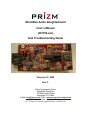
MicroMux Audio Daughterboard
User’s Manual
(201150-xxx)
And Troubleshooting Guide
February 23, 2009
Rev C.
Moog Components Group
Springfield Operations
750 West Sproul Road
Springfield, PA 19064
E-Mail: [email protected] URL: www.moog.com/components
Tel: 610-328-4000 Fax 610-605-6216
24/7 Technical Customer Support Hotline: 610-605-6101
Moog Components Group
MICROMUX Audio Daughterboard
(201150-xxx)
February 23, 2009
TABLE OF CONTENTS
ERROR! BOOKMARK NOT DEFINED. MICROMUX AUDIO DAUGHTERBOARD P/N – 201150-XXX ................3
1.1
MICROMUX AUDIO DAUGHTERBOARD MANUAL REVISION HISTORY ...................................................................3
1.2
MICROMUX AUDIO DAUGHTERBOARD DASH (-) NUMBER DEFINITIONS ...............................................................3
1.3
MICROMUX AUDIO DAUGHTERBOARD OPERATION ...............................................................................................3
1.4
MICROMUX AUDIO DAUGHTERBOARD INDICATORS AND CONTROLS ...................................................................4
1.4.1
MicroMux Audio Daughterboard Specifications ...........................................................................................6
1.4.2
MicroMux Audio Daughterboard Dimensions..............................................................................................7
1.4.3
MicroMux Audio Daughterboard Power Requirements ................................................................................7
1.5
MICROMUX AUDIO DAUGHTERBOARD PTT SELECTIONS ......................................................................................7
1.6
MICROMUX AUDIO INPUTS SELECTIONS.................................................................................................................9
1.7
MICROMUX AUDIO OUTPUT SELECTIONS .............................................................................................................10
1.8
MICROMUX AUDIO DAUGHTERBOARD ADJUSTMENT AND TROUBLESHOOTING .................................................11
1.8.1
Power Section Testing ...................................................................................................................................11
Page 2 of 12
I:\Baltimore\Manuals in WORD Format\MicroMux line\New Rev-MM line\201150-xxx MicroMux Audio DB Manual Rev C.doc
Last printed 2/23/2009 3:59:00 PM
Moog Components Group
MICROMUX Audio Daughterboard
(201150-xxx)
February 23, 2009
1 MicroMux Audio Daughterboard P/N – 201150-xxx
The MicroMux Audio daughterboard must be used with a MicroMux motherboard. This
daughterboard set provides a single bi-directional audio channel with a selectable 1Watt audio output
power amp. The daughterboard also contains push-to-talk (PTT) microphone keying circuitry that can
be selected to turn off the local speaker automatically when the microphone is keyed (enabled). This
feature can be used to break the microphone
1.1 MicroMux Audio Daughterboard Manual Revision History
The MicroMux Audio Daughterboard User’s Manual and Troubleshooting Guide has gone through the
following revisions:
Jan. 2004
Jan. 2004
Sep. 2005
Feb.2009
Preliminary
Rev A
Rev B
Rev C
Updated contact information to reflect Moog Components Group.
1.2 MicroMux Audio Daughterboard Dash (-) Number Definitions
The MicroMux Video Input and Output boards have a Dash Number appended to the part number.
This Dash Number identifies the specific board configurations:
MicroMux Audio Daughterboard 201150-xxx
Dash
Number
Board Assy. Specific Options
Rev.
Rev.
-001C
A
A
PTT Logic Enabled
-002C
A
A
No connectors
-002D
A
A
With connectors
-003B
A
A
Pressure Tolerant
1.3 MicroMux Audio Daughterboard Operation
Page 3 of 12
I:\Baltimore\Manuals in WORD Format\MicroMux line\New Rev-MM line\201150-xxx MicroMux Audio DB Manual Rev C.doc
Last printed 2/23/2009 3:59:00 PM
Moog Components Group
MICROMUX Audio Daughterboard
(201150-xxx)
February 23, 2009
The MicroMux Audio daughterboard requires +5VDC power that is supplied by the motherboard via the
daughterboard connector. The daughterboards also have an on-board +5VDC to +12VDC/-12VDC
converter to provide power for the analog amplifiers.
1.4
MicroMux Audio Daughterboard Indicators and Controls
LEDs: There are 9 surface mount (SMD) LED indicators on the MicroMux Audio daughterboard to
indicate different statuses that are covered by function below.
NOTE: D8, D12 thru D14 are protection diodes not LEDs.
LED
Indication
D1 (Green)
labeled “5V”: ‘ON’ if +5VDC is available to the board
D2 (Green)
labeled “AUD OUT”: 'ON' if output signal level exceeds approximately 1.15V
D3 (Green)
labeled “+12V”: 'ON' if +12VDC is available on the board
D4 (Green)
labeled “-12V”: 'ON' if -12VDC is available on the board
D5 (Green)
labeled “AUD IN”: 'ON' if input signal level exceeds approximately 1.15V
D6 (Green)
labeled “SPKR”: 'ON" if speaker (or audio output) is enabled
D7 (Green)
labeled “MIC”: 'ON' if PTT is pressed keying the microphone
D9 (Green)
labeled “TLK”: 'ON' if the transmit link is synchronized on the daughterboard
D10 (Green)
labeled “RLK”: 'ON' if the receive link is synchronized on the daughterboard
For normal operation the following LEDs MUST be lit solidly:
“+5V” LED
“+12V” LED
“-12V” LED
“RLK” LED
“TLK” LED
NOTE: If the above LEDs are NOT lit, refer to the Troubleshooting Section
FUSE: There are no fuses on this board, only on the motherboard
SWITCHES: There are no switches on this board.
Page 4 of 12
I:\Baltimore\Manuals in WORD Format\MicroMux line\New Rev-MM line\201150-xxx MicroMux Audio DB Manual Rev C.doc
Last printed 2/23/2009 3:59:00 PM
Moog Components Group
CONNECTORS:
J1
MICROMUX Audio Daughterboard
(201150-xxx)
February 23, 2009
The connector on the MicroMux Audio daughterboard is as follows:
Audio Connector
PTT (IN)
GROUND
OUT+ (OUT)
GROUND
IN+ (IN)
MIC POWER (OUT)
1
3
5
7
9
11
o
o
o
o
o
o
o
o
o
o
o
o
2
4
6
8
10
12
PTT_GND (IN)
GROUND
OUT- (OUT)
GROUND
IN- (IN) OR GND (SINGLE ENDED)
GROUND
NOTE: Various jumper settings affect the signals on J1.
Jumper Summary:
There are 11 jumpers on the MicroMux Audio daughterboard:
Note: PIN 1 is denoted by a square pad on the printed circuit board.
Note: Placement of a jumper shunt is denoted below by a single vertical line.
JP1: ISP Programming Header (FACTORY USE ONLY)
1 o o 2
3 o o 4
(NO SHUNTS ALLOWED)
5 o o 6
7 o o 8
JP2: Audio Power Amp Input Enable/Disable (also set JP3 and JP4)
1 o
1 o
| Disables Power Amp
2 o
2 o
|
Enables Power Amp
3 o
3 o
JP3: OUT+ Source Selection (also JP2 and JP4)
1 o
1 o
| Selects Power Amp OUT+
2 o
2 o
|
Selects Voltage Output
3 o
3 o
JP4: OUT- Source Selection (set also JP2 and JP3)
1 o
1 o
| Selects Power Amp OUT2 o
2 o
|
Selects Voltage Output
Page 5 of 12
I:\Baltimore\Manuals in WORD Format\MicroMux line\New Rev-MM line\201150-xxx MicroMux Audio DB Manual Rev C.doc
Last printed 2/23/2009 3:59:00 PM
Moog Components Group
3 o
MICROMUX Audio Daughterboard
(201150-xxx)
3 o
February 23, 2009
(grounds pin)
JP5: Electret Microphone Amplifier Input Enable/Disable (set also JP7)
1 o
1 o
| Disables Electret Amp
2 o
2 o
| Enables Electret Amp
3 o
3 o
|
4 o
4 o
JP6:
Single-ended/Differential Input Selection
1 o
1 o
| Single-ended Selected
Differential Selected
2 o
2 o
JP7: Electret Microphone Amplifier Output Enable/Disable
1 o
1 o
| Enables Electret Output
Disables Electret Output
2 o
2 o
JP8: N.O. or N.C PTT Switch Selection
1 o==o o 3 N.O. Switch
1 o o==o 3 N.C. Switch
2
2
JP9: Power Amplifier Shutdown Selection
3 o==o o 1 LSI Control
3 o o==o 1 Local Control
2
2
JP10: Electret Power Supply Selection
3 o==o o 1 3-Wire Configuration 3 o o==o 1 2-Wire Configuration
2
2
JP11: Local/Remote Location Selection
1 o o 2 Local Location
1 o==o 3 Remote Location
1.4.1 MicroMux Audio Daughterboard Specifications
Audio (basic specifications)
Number of Channels: 1 bi-directional
Analog Resolution:
10-bit
Analog Sample Rate: 1.1 Megasamples per second (Msps), typically
Analog Bandwidth:
20 – 20KHz audio bandwidth
Audio Levels (In/Out): 1Vp-p, typically 0.1Vp-p to 10Vp-p range
Analog Adjustment:
adjustable input and output audio via gain trimpots
Analog Input:
selectable single-ended or differential (balanced)
Page 6 of 12
I:\Baltimore\Manuals in WORD Format\MicroMux line\New Rev-MM line\201150-xxx MicroMux Audio DB Manual Rev C.doc
Last printed 2/23/2009 3:59:00 PM
Moog Components Group
MICROMUX Audio Daughterboard
(201150-xxx)
Analog Output:
selectable single-ended or differential (balanced)
Power Amplifier
Selectable:
Audio Power:
jumper selectable for amplifier or voltage output
1Watt into 8-ohm speaker
Electret Microphone
Selectable:
Audio Input Level:
Mic DC Power:
Power Options:
jumper selectable Electret Mic amplifier
5milliVolts, typical
1.2Vdc power supply
2-wire or 3-wire configuration
Push-to-Talk
Selectable:
February 23, 2009
jumper selectable for Local or Remote
-- Local for control console location
-- Remote for robot location
NOTE: optionally the PTT function can be disabled to provide full-time (un-switched) bi-directional
audio.
Daughterboard DC Operating Power
Voltage:
+5VDC supplied via daughterboard connector from motherboard
Current Required:
750milliAmps, typically
Misc.
Operating Temperature:
0 degree C to 65 degree C
(except high temp version which is -20 deg C to 70 deg C)
1.4.2 MicroMux Audio Daughterboard Dimensions
Printed circuit board (PCB): 4.01 in x 1.9 in x 0.60 in board-to-board
(101.854 mm x 49.26 mm x 15.24 mm)
1.4.3 MicroMux Audio Daughterboard Power Requirements
+5 Volts at 1.0 Amps (5.0 Watts), maximum
1.5 MicroMux Audio Daughterboard PTT Selections
The PTT function assumes that the audio daughterboard is used to operate a robot from a control
console. The control console (LOCAL location) is assumed to have a microphone controlled by a PTT
switch and a speaker output – with or without an external audio power amp. The robot (REMOTE
location) is assumed to have a microphone and a speaker output – with or without an external audio
power amp – but there is no PTT function at this un-manned location.
Page 7 of 12
I:\Baltimore\Manuals in WORD Format\MicroMux line\New Rev-MM line\201150-xxx MicroMux Audio DB Manual Rev C.doc
Last printed 2/23/2009 3:59:00 PM
Moog Components Group
MICROMUX Audio Daughterboard
(201150-xxx)
February 23, 2009
NOTE: Because the functioning of the PTT logic is different between the Local and the Remote
location a jumper shunt must be placed or removed to identify the daughterboard's physical location.
"LOCAL"/"REMOTE" selection (JP11)
The location of the daughterboard can be selected by setting a jumper shunt on J11.
JP11
1 o o 2 No shunt placed – “LOCAL” location selected
JP11
1 o==o 2
Shunt placed – “REMOTE” location selected
PTT switch selection (JP8)
1. If the JP8 shunt is place towards the left then a normally-opened (N.O.) switch is selected – the
switch will be electrically open until pressed then it is closed.
2. If the JP8 shunt is placed to the right then a normally-closed (N.C.) switch is selected – the switch
will be electrically closed until pressed then it is open.
J10
1 o==o
2
o 3
Shunt placed 1-2 – N.O. switch selected
J10
1 o
o==o 3
2
Shunt placed 2-3 – N.C. switch selected
In either case the “MIC” LED should only light when the PTT switch is closed. If the LED does not
change state appropriately, swap the shunt location. If it still does not light check the PTT switch
connections.
NOTE: For correct operation of the PTT logic within the audio daughterboard, the boards must be
configured for either the “LOCAL” or “REMOTE” position. Incorrect placement of the shunt will
cause the PTT function to operate incorrectly.
At the “LOCAL” location - when the PTT switch is pressed, the “MIC” LED should light and the
“SPKR” LED should turn off. At the “REMOTE” location- the “MIC” LED will remain off (as no
switch is connected) while the “SPKR” LED will light when the “LOCAL” PTT switch is pressed.
LED Statuses
“LOCAL” Location
PTT Switch
“MIC” LED
Open/not
OFF
pressed
Closed/pressed ON
‘SPKR” LED
ON
“REMOTE” Location
“MIC” LED
“SPKR” LED
OFF
OFF
OFF
OFF
Audio Functions
“LOCAL” Location
ON
“REMOTE” Location
Page 8 of 12
I:\Baltimore\Manuals in WORD Format\MicroMux line\New Rev-MM line\201150-xxx MicroMux Audio DB Manual Rev C.doc
Last printed 2/23/2009 3:59:00 PM
Moog Components Group
PTT Switch
Open/not
pressed
Closed/pressed
MICROMUX Audio Daughterboard
(201150-xxx)
February 23, 2009
Microphone
Disabled
Speaker
Enabled
Microphone
Enabled
Speaker
Disabled
Enabled
Disabled
Disabled
Enabled
1.6 MicroMux Audio Inputs Selections
The audio input stage has several selectable options:
1. Either unity-gain or high-gain Electret amplifier
2. Either single-ended (un-balanced) or differential (balanced) amplifier input
3. Either 1.2VDC or 5VDC microphone power
1. If the audio input is a high-level output device (anywhere between approximately 0.1Vp-p to 10Vpp) then the unity-gain input is appropriate. If the input is an Electret microphone then the high-gain
selection is appropriate. This is selected by setting both JP5 and JP7.
JP5: Electret Microphone Amplifier Input Enable/Disable (set also JP7)
1 o
1 o
| Disables Electret Amp
2 o
2 o
| Enables Electret Amp
3 o
3 o
|
4 o
4 o
JP7: Electret Microphone Amplifier Output Enable/Disable
1 o
1 o
| Enables Electret Output
Disables Electret Output
2 o
2 o
2. If the input source is single-ended (i.e. signal referenced to ground or un-balanced) or if the input is
differential (i.e. a positive and a negative version of the signal or balanced) this can be selected by
moving the shunt on JP6
JP6:
Single-ended/Differential Input Selection
1 o
1 o
| Single-ended Selected
Differential (balanced) Selected
2 o
2 o
NOTE: If Single-ended selected then attach input signal to IN+ and its return to IN- (grounded by the
jumper).
If Differential input is selected then attach positive input signal to IN+ and the negative input
signal to IN-. Shield (if used) can be attached to any Ground pin.
Page 9 of 12
I:\Baltimore\Manuals in WORD Format\MicroMux line\New Rev-MM line\201150-xxx MicroMux Audio DB Manual Rev C.doc
Last printed 2/23/2009 3:59:00 PM
Moog Components Group
MICROMUX Audio Daughterboard
(201150-xxx)
February 23, 2009
3. If the input is an Electret microphone then a DC power supply MAY be required. If so, then JP6
will select the voltage connection type - either a 3-Wire or a 2-Wire cofiguration.
JP10: Electret Power Supply Selection
3 o==o o 1 3-Wire Configuration 3 o o==o 1 2-Wire Configuration
2
2
1.7
MicroMux Audio Output Selections
The audio output stage has several selectable options:
1. Single-ended voltage (un-balanced) output
2. 1-Watt audio power amplifier (balanced) output
1. If the audio output is an un-balanced voltage output (anywhere between approximately 0.1Vp-p to
10Vp-p) then this is appropriate. This is selected by setting JP2, JP3 and JP4.
JP2: Audio Power Amp Input Enable/Disable (also set JP3 and JP4)
1 o
| Disables Power Amp
2 o
3 o
JP3:
1 o
2 o
|
3 o
JP4:
1 o
2 o
|
3 o
OUT+ Source Selection (also JP2 and JP4)
Selects Voltage Output
OUT- Source Selection (set also JP2 and JP3)
Selects Voltage Output
2. If the audio output is a direct connection to a speaker with the 1-Watt audio power amplifier then
this is appropriate. This is selected by setting JP2, JP3 and JP4.
JP2: Audio Power Amp Input Enable/Disable (also set JP3 and JP4)
1 o
Page 10 of 12
I:\Baltimore\Manuals in WORD Format\MicroMux line\New Rev-MM line\201150-xxx MicroMux Audio DB Manual Rev C.doc
Last printed 2/23/2009 3:59:00 PM
Moog Components Group
2 o
|
3 o
JP3:
1 o
|
2 o
MICROMUX Audio Daughterboard
(201150-xxx)
February 23, 2009
Enables Power Amp
OUT+ Source Selection (also JP2 and JP4)
Selects Power Amp Output
3 o
JP4:
1 o
|
2 o
OUT- Source Selection (set also JP2 and JP3)
Selects Power Amp Output
3 o
1.8 MicroMux Audio Daughterboard Adjustment and Troubleshooting
For normal operation the following LEDs MUST be lit solidly:
“+5V” LED
“+12V” LED
“-12V” LED
“RLK” LED
“TLK” LED
1.8.1 Power Section Testing
If the "+5V", "+12" and "-12" Power LEDs are out:
• Check for continuity of fuse F1 on the MicroMux motherboard with an ohmmeter.
• Replace fuse if blown.
If only the "+5V" Power LED is out:
• Verify +5V DC is present at the source
• If +5V is not available replace the board with a spare.
• If +5V is available check the display LED (D1).
If only the "+12" Power LED is out:
• Verify +12V DC is present at the source U4 DC-DC converter at pin 5
• If +12V is not available replace the board with a spare.
• If +12V is available check the display LED (D3).
If only the "-12" Power LED is out:
Page 11 of 12
I:\Baltimore\Manuals in WORD Format\MicroMux line\New Rev-MM line\201150-xxx MicroMux Audio DB Manual Rev C.doc
Last printed 2/23/2009 3:59:00 PM
Moog Components Group
•
•
•
MICROMUX Audio Daughterboard
(201150-xxx)
February 23, 2009
Verify -12V DC is present at the source
If -12V is not available replace the board with a spare.
If -12V is available check the display LED (D4).
Page 12 of 12
I:\Baltimore\Manuals in WORD Format\MicroMux line\New Rev-MM line\201150-xxx MicroMux Audio DB Manual Rev C.doc
Last printed 2/23/2009 3:59:00 PM