1
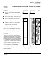
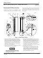
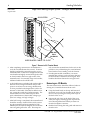
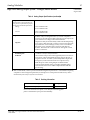
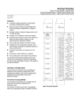
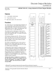
This Datasheet for the
IC697ALG320
Analog Input, Voltage/Current, 8 Channels.
http://www.qualitrol.com/shop/p-14748-ic697alg230.aspx
Provides the wiring diagrams and installation guidelines for this GE Series 90-30
module.
For further information, please contact Qualitrol Technical Support at
1-800-784-9385
[email protected]
1
Analog Modules
IC697ALG320
58
GFK-0388G
August 1997
High Level Analog Output System - Voltage/Current Module
High Level Analog Output System - Voltage/Current Module (IC697ALG320)
datasheet GFK-0388G
Features
D
High Level Analog voltage and current outputs on
one module
D
Output module has four outputs individually configurable for voltage or current
D
Provides unipolar or bipolar Analog voltage outputs
up to Ç 10 volts full scale
D
D
D
D
D
Provides 0 to 22.5 milliamp current loop signals
Individual user scaling on each output channel
Fast update rate
a44034
OK
OK
1
3
1I
CHANNEL 1
4
GND
6
N.C.
8
+
10
7
I
11
2I
12
2V
13
CHANNEL 2
GND
14
N.C.
16
+
18
15
GND
17
I
19
3I
20
3V
21
GND
22
N.C.
24
CHANNEL 3
23
GND
25
+
I
26
27
4I
Analog outputs use %AQ references in the PLC. A
maximum of 8K words of %AQ memory is available
in the PLC. Each output channel uses one word (16
bits) of %AQ memory.
GND
9
Functions
The basic converter is 16 bits resolution (1 part in
65536) with 14-bit monotonicity. Outputs are isolated
from the backplane and are protected against transient and steady-state overvoltage conditions.
1V
5
Calibrated at factory with factory calibration data
stored in non-volatile EEPROM memory
The high level Analog Output system for the Programmable Logic Controller (PLC) accepts digital data
from the CPU or other controllers accessing the PLC
backplane. This output data is converted by a Digital
to Analog (D/A) converter to analog outputs of up to
10 volts full scale, or 0 to 22.5 milliamp current loop
signals.
I
2
+
No jumpers or DIP switches for user to configure
Easy configuration using the configuration function of
the MS-DOSr or Windowsrprogramming software
running on Windowsr 95 or Windows NTr over
Ethernet TCP/IP or through the SNP port. The Programming Software configuration function is installed
on the programming device. The programming device can be an IBMr XT, AT,PS/2r or compatible Personal Computer.
OUTPUT
ANALOG (V&I)
OUTPUT
ANALOG (V&I)
HIGH LEVEL
28
4V
29
CHANNEL 4
SLOT
GND
30
N.C.
32
31
GND
33
N.C.
V
34
USER
35
N.C.
COM
36
COM
38
GND
40
37
COM
39
GND
MODULE IC697ALG320
LABEL 44A726758–020R02
Figure 1. High Level Analog Output Module
r IBM and PS/2 are registered trademarks of International Business Machines Corporation.
r MS-DOS, Windows, Windows 95, and Windows NT are registered trademarks of Microsoft Corporation.
t
Series 90 -70 Programmable Controller Data Sheet Manual
GFK-0600F
58-1
Analog Modules
2
GFK-0388G
August 1997
High Level Analog Output System - Voltage/Current Module
System Operation
A block diagram of the IC697ALG320 High Level Analog Output module and an example of user field wiring connections to the module are shown below.
Î
Î
Î
ÎÎ
Î
ÎÎÎ
ÎÎÎÎ
Î
ÎÎÎ
Î
Î
ÎÎÎ
VOUT
VOLTAGE
OUTPUT
a43970
10V
VLOAD
VRET
CH 1
GND
JUMPER FOR
OUTPUT
REF
PLC
BACKPLANE
OPTO–
ISOLATION
D
V
OUT
A
4–20MA
LOAD
RET
GND
VC
VOUT
VOLTAGE
OUTPUT
VRET
CH 2
GND
REF
V
OUT
RET
GND
PWR +
USER
POWER SUPPLY
PWR
.001
VCM
10K
GND
MODULE
GROUND
USER
GROUND
Figure 2. Block Diagram and User Wiring Information for IC697ALG320
Connections for both voltage and current loads are
shown in the above illustration. Note the following
regarding the illustration:
1. Each output may be configured for either voltage
or current - not both.
2. If used as a current output you must jumper VOUT
to IREF.
58-2
3. Power for the voltage output is derived from the
PLC backplane. Power for the 4 to 20 mA current
output must be supplied by the user. A single connection (PSPOS and PSNEG) serves all four channels.
t
Series 90 -70 Programmable Controller Data Sheet Manual
GFK-0600F
Analog Modules
3
GFK-0388G
August 1997
High Level Analog Output System - Voltage/Current Module
Channel-to-Channel Compliance
User Wiring Connections
While it is expected that output loads will be floating
or tied to the same potential (normally ground), the
module is designed to allow up to 0.5 VDC compliance voltage (labeled VC in the previous illustration) difference between outputs and still operate
within specifications. This prevents ground loop currents or errors from occurring due to small differences
in ground potential at different locations. Note that in
addition to this offset, outputs will operate properly in
the presence of a large amount of high frequency
noise (refer to specifications).
As shown in the previous illustration. the output circuitry is isolated from the PLC backplane. This allows
the module to operate within specifications with a
common mode voltage of up to Ç 60V from ground
(shown as VCM in the illustration). It must be observed, however that the entire output section of the
module (all four channels) operates at a singleoffset
voltage from ground potential. Common mode voltage between outputs must be within the specifications
stated in the previous paragraph.
Figure 4 shows the wiring assignments for the screw
terminals on the terminal board on the Analog Output module. In addition to the information in this
data sheet, circuit wiring diagrams are printed on the
inside surface of the label inserted in the module’s
hinged door.
OUTPUT
ANALOG ( V &
IOUT
+
1I
2
3
4
I RET
GND
GND
+
2I
I RET
GND
I OUT
11
12
GND
+
3I
GND
GND GND
16
I REF
18
19
+
a43972
+
4I
I RET
V RET
22
GND GND
24
25
I REF
27
VOUT
26
4V
28
V RET
29
GND
GND
30
22
PWR
19.2
V
USER
COM
36
PWR
COM
38
GND
GND
40
14
12
10
600
800
R
L
Figure 3. User Power vs. Load Impedance
Series 90 -70 Programmable Controller Data Sheet Manual
GFK-0600F
GND
33
N.C.
35
N.C.
37
COM
PWR
39
GND
GND
GND
34
MIN
16
31
32
24
PWR
VOUT
3V
23
N.C.
N.C.
t
V RET
21
GND
V OUT
14
MAX
400
+
2V
20
I RET
26
200
I REF
10
17
28.8
18
GND GND
8
13
I OUT
20
VRET
9
I OUT
V OUT
6
7
N.C.
N.C.
This module will accommodate a wide range of load
impedance; up to 800 ohms. The range of allowable
power supply voltage for a given load impedance is
shown in Figure 3. For example, a 24V Ç 20% supply
(19.2 to 28.8 volts) will provide sufficient power with
loads from 200 to 550 ohms.
28
+
1V
5
User Power for Current Loops
30
I REF
1
15
V (USER POWER
SUPPLY)
a43973
)
MODULE IC697ALG320
Figure 4. Field Wiring Connections to Module’s
I/O Terminal Board
58-3
Analog Modules
4
GFK-0388G
August 1997
High Level Analog Output System - Voltage/Current Module
Connections to User Devices
Connections to the Analog Output module from user
devices are made to screw terminals on a removable
40-terminal connector block mounted on the front of
the module. All field connections to the outputs
should be wired to the I/O terminal board using a
good grade of twisted, shielded instrumentation
cable. Separate connections are provided on the terminal board for both current outputs and voltage outputs for each channel. Actual terminals used are determined by the configuration that has been selected
for each individual channel.
Ground connections for each channel, labeled GND,
on the terminal board are provided for connecting
VOLTAGE:
V OUT
+
V
shields. This ground connection is made directly to
the rack, resulting in superior rejection of noise
caused by any shield drain currents. Actual selection
of ground location may be influenced by system power and ground considerations. However, best operation will be obtained when system ground is physically close to the rack containing the analog circuits.
Normally, the shield is grounded at only one end (see
Figure 5).
For additional system grounding information refer to the
discussion on system grounding in chapter 3 of the Programmable Controller Installation Manual.
The module provides electrical isolation of externally
generated noise between the output field wiring and
the backplane through use of optical isolation.
Î
Î
REF
OUT
USER
DEVICE
V OUT
V RET
GND
a43974
CURRENT:
Î
RET
Î
V RET
NC
GND
SHIELD CONNECTED
AT MODULE END ONLY
Î
Î
Î
Î
Î
Î
USER
DEVICE
SHIELD CONNECTED
AT MODULE END ONLY
Figure 5. Cable Connections to Field Devices
58-4
t
Series 90 -70 Programmable Controller Data Sheet Manual
GFK-0600F
Analog Modules
5
GFK-0388G
August 1997
High Level Analog Output System - Voltage/Current Module
Recommended Field Wiring Procedures
The following procedures are recommended when
connecting field wiring to the detachable terminal
board on the Analog Output module. Module features
referenced in the following procedures which are common to all IC697 I/O modules are illustrated in the following figure.
a43855
JACKSCREW
HINGED
DOOR
TERMINAL
BOARD
CORD
TIE
ÎÎ
ÎÎ
CORD
TIE
CLEAT
ÎÎ
ÎÎ
ÎÎÎÎ
ÎÎÎÎ
ÎÎÎÎ
ÎÎÎÎ
ÎÎÎÎ
ÎÎÎÎ
ÎÎÎÎ
ÎÎÎÎ
ÎÎÎÎ
ÎÎÎÎ
ÎÎÎÎ
ÎÎÎÎ
Î
Î
ÎÎÎÎ
Î
Î
JACKSCREW
Î
CORD
TIE
CLEAT
CORD
TIE
STRAP
CLEAT
Î
Î
Î
Î
STRAP
STRAP
Figure 6. I/O Module Common Features
1. Turn off power before removing or installing terminal boards. Open the hinged door on the module to access a jackscrew which holds the terminal
board securely in place. The Detachable field wiring terminal board can now be removed from the
module by turning the jackscrew counter-clockwise until it is fully disengaged.
2. To remove the terminal board, grasp the top of the
terminal board and swing it outward.
Caution
Do not use the hinged door to remove the
terminal board. The hinged door could
be damaged if this is done.
t
Series 90 -70 Programmable Controller Data Sheet Manual
GFK-0600F
3. The terminal board is designed to accept wire sizes
from AWG #22 (0.36 mm2) through AWG #14 (2.10
mm2). It is important that when using AWG #14
(2.10 mm2) wire for wiring all points, that a maximum insulation diameter of .135 inch (3.43 mm) not
be exceeded. To ensure proper connection, two
wires may be terminated on any one terminal only if
both wires are the same size.
4. The terminal board is designed to accept a maximum of (40) AWG #14 (2.10 mm2)wires. If AWG
#14 (2.10 mm2) wires are to be used, then wire
markers should be placed at least 8 inches (203
mm) from termination end to provide sufficient
space for the hinged door to close.
58-5
Analog Modules
6
GFK-0388G
August 1997
High Level Analog Output System - Voltage/Current Module
ÎÎÎ
ÎÎ
ÎÎÎ
ÎÎ
ÎÎÎ
Î
ÎÎ
ÎÎÎ
Î
ÎÎ
ÎÎÎ
ÎÎÎ
ÎÎÎ
ÎÎ
Î
ÎÎÎ
Î
ÎÎÎ
ÎÎ
Î
ÎÎ
ÎÎÎ
ÎÎÎ
Î
ÎÎ
Î
JACKSCREW
a43747
ÎÎ
ÎÎ
ÎÎ
ÎÎÎÎÎÎÎ
ÎÎ
Î
ÎÎ
Î
ÎÎÎÎÎ
ÎÎÎÎÎ
DO NOT
PULL
ON DOOR
WIRE BUNDLE CABLE TIE CLEAT
Figure 7. Removal of I/O Terminal Board
5. After completing connections to all modules in a
rack, the wire bundle must be secured. To ensure
that the wire bundle is secured properly, it is recommended that a cable tie be wrapped around the
wire bundle and tightly secured through the cable
tie cleat located at the lower right corner of the
terminal board. For extremely large wire bundles,
additional cable ties should be used.
only secures the terminal board to the rack, it also
provides a way of identifying the wired terminal
board with its correct mating rack slot location.
8. For adequate module ventilation, it is recommended that at least a 5 inch (127 mm) clearance
be allowed above and below the rack grill. Wire
bundles should not obstruct the rack grill work.
6. A door label insert is included with each module to
indicate circuit wiring information and provide
space to record user circuit wiring identification.
A slot is provided on the hinged door to allow for
insertion of this label. If the label is difficult to insert, crease the scored edge before insertion. The
outside label has a color coded stripe to allow
quick identification of the module voltage type
(blue: low voltage; red: high voltage).
Removing an I/O Module
7. After field wiring is completed, the terminal board
should be securely fastened to the rack by inserting the terminal board strap (attached to each
module) into the small rectangular slots in the bottom card guide grill on the rack. This strap not
58-6
The instructions below should be followed when removing an I/O module from its slot in a rack.
D Grasp the board firmly at the top and bottom of
the board cover with your thumbs on the front of
the cover and your fingers on the plastic clips on
the back of the cover.
D Squeeze the rack clips on the back of the cover
with your fingers to disengage the clip from the
rack rail and pull the board firmly to remove it
from the backplane connector.
D Slide the board along the card guide and remove it
from the rack.
t
Series 90 -70 Programmable Controller Data Sheet Manual
GFK-0600F
Analog Modules
7
GFK-0388G
August 1997
High Level Analog Output System - Voltage/Current Module
Module/R ack Configuration
configuring the slot to accept only identical module
types.
A high level analog output system for the programmable controller can consist of multiple Analog Output modules providing up to a maximum of 252 output channels.
If it is necessary to change the module location in the
rack after the key has been latched onto the center rail
of the rack, the key can be removed by pushing it upward to unhook the latch while pushing it off the rail.
It may then be reinserted into the rack at the desired
location.
A maximum of seven Analog Output modules can be
installed in a CPU rack, and a maximum of eight Analog Output modules can be installed in an expansion
rack.
Channel numbers for each Analog Output module in
a system are assigned by the system.
ÎÎ
ÎÎ
ÎÎ
ÎÎ
ÎÎ
ÎÎ
ÎÎ
ÎÎ
ÎÎ
Î
ÎÎ
ÎÎ
ÎÎ
ÎÎ
ÎÎ
ÎÎ
ÎÎ
ÎÎ
ÎÎ
Î
*
*
*
*
*
*
*
ÎÎ
ÎÎ
ÎÎ
ÎÎ
ÎÎ
ÎÎ
ÎÎ
ÎÎ
ÎÎ
Î
ÎÎ
ÎÎ
ÎÎ
ÎÎ
ÎÎ
ÎÎ
ÎÎ
ÎÎ
Î
ÎÎÎ
Î
ÎÎ
ÎÎ
ÎÎ
ÎÎ
ÎÎ
ÎÎ
ÎÎ
ÎÎ
ÎÎ
Î
ÎÎ
ÎÎ
ÎÎ
ÎÎ
ÎÎ
ÎÎ
ÎÎ
ÎÎ
ÎÎ
Î
ÎÎÎÎÎÎÎÎÎÎÎÎÎÎÎÎÎÎÎ
MAIN RACK
P
S
a43975
C B
P T
U M
7 EXPANSION
RACKS
(MAXIMUM)
Configurable Functions
You can configure certain functions through the
MS-DOS or Windows software configurator function using the programming computer. These functions include output ranges, user scaling, and fault
reporting. Each of these functions and their definitions are listed in Table 1.
ANALOG OUTPUT
* MODULES
CAN BE
INSTALLED IN ANY
OF THESE SLOTS
ÎÎ
ÎÎ
ÎÎ
ÎÎ
ÎÎ
ÎÎ
ÎÎ
ÎÎ
ÎÎ
Î
ÎÎ
ÎÎ
ÎÎ
ÎÎ
ÎÎ
ÎÎ
ÎÎ
ÎÎ
ÎÎ
Î
ÎÎ
ÎÎ
ÎÎ
ÎÎ
* ÎÎ
* *ÎÎ
*ÎÎ
*ÎÎ
*ÎÎ
*Î
ÎÎÎÎÎÎÎÎÎÎÎÎÎÎÎÎÎ* Î
ÎÎÎ
ÎÎ
ÎÎ
ÎÎ
ÎÎ
ÎÎ
ÎÎ
ÎÎ
ÎÎ
Î
ÎÎÎ
Î
ÎÎÎÎÎÎÎÎÎÎÎÎÎÎÎÎÎÎÎ
ÎÎ
ÎÎ
ÎÎ
ÎÎ
ÎÎ
ÎÎ
ÎÎ
ÎÎ
ÎÎ
Î
ÎÎÎÎÎÎÎÎÎÎÎÎÎÎÎÎÎÎÎ
EXPANSION RACK
B
R
M
Figure 8. Example of Analog Output Module Installation
Module Mechanical Keying
Each module includes a mechanical key that prevents
inadvertent substitution of one module type for
another in a given slot. The key fits a uniquely
shaped area on the board below the connector.
When the module is first installed, the key latches
onto the backplane center rail. When the module is
extracted, the key remains in the center rail, thereby
t
Note that in an IC697CHS PLC rack only the power
supply can be placed in the leftmost slot in the rack, and
slot 1 (adjacent to the power supply) must always contain a CPU (in rack 0 - the CPU rack), or a Bus Receiver
Module or Remote I/O Scanner (in expansion racks).
Series 90 -70 Programmable Controller Data Sheet Manual
GFK-0600F
Module Configuration Data
After the CPU has been updated, the Analog Output
module is ready for configuration data. The CPU provides the following module configuration data
D
The output circuit type (voltage or current) for
each output channel
D
CPU fault reporting interrupt, whether enabled
or disabled on a per channel
D
The default value for outputs and whether outputs are enabled or disabled on system failure or
CPU command
Each of the output channel values is checked for overrange, underrange, and open wire; open wire only if
configured for current range.
Note
For more detailed information on using the
configuration function, refer to the Programming Software User’s Manual.
58-7
Analog Modules
8
GFK-0388G
August 1997
High Level Analog Output System - Voltage/Current Module
Table 1. Configurable features for IC697ALG320
Feature
Channel or Module
Selections
Default Setting
–10V, +10V
0V, +10V
Voltage/Current
Channel
–5V, +5V
–10V, +10V
0V, +5V
4, 20 mA
Report Faults
Channel
Scaling Points
Channel
User Value
mV or mA
Enabled/Disabled
Enabled
Ç 32767 µA
+20000, –4000 µA
Ç 10000 mV
+10000 mV, –10000 mV
Output Default
Channel
Hold/Off
Off
Default Value
Channel
Ç 32767
0
Output Ranges
For each output circuit, the range selected during configuration should match the signal. The 4 to 20 milliamp range can be used for current output devices.
For current loop operation, the terminal board jumper
for each applicable channel must be installed (refer to
Figure 4, Field Wiring Connections to I/O Terminal
Board).
Output Default
Output Default mode is activated when the CPU output data is not being received, such as during powerup, when the CPU is stopped, or CPU communications have been lost. When this occurs, each channel
can be configured to Hold Last State or default to a
configured Default Value. If configured to Hold Last
State, the channel will maintain the last output value
received from the CPU until communications resume.
If Output Default is configured to OFF, the configured
Default Value is applied.
Note that the data available to the outputs will be different according to where the system is in relation to
time (starting at power-up). This time vs. output data
relationship is shown below (Figure 9).
Default Value
If the Output Default is set to OFF, this value, programmed in Engineering Units, is applied to the output until communications are restored.
CONDITION
POWER
UP
OUTPUTS
AT
0
CONFIGURATION
RECEIVED FROM CPU
(CPU STOPPED)
CPU
RUNNING
(I/O SCAN)
OUTPUTS AT
DEFAULT VALUE
(EVEN WITH HOLD
LAST STATE ACTIVE)
OUTPUTS AT
LAST SCAN
VALUE
SYSTEM FAILURE
OR
PLC SOFTWARE
RESET
HOLD
LAST STATE
OR
DEFAULT
(USER CONFIG)
STATE
a43977
CPU
STOP
OUTPUTS AT
LAST SCAN
VALUE
Figure 9. Time vs. Output Data Relationship
58-8
t
Series 90 -70 Programmable Controller Data Sheet Manual
GFK-0600F
Analog Modules
9
GFK-0388G
August 1997
High Level Analog Output System - Voltage/Current Module
software configurator function. Scaling is set by entering the desired voltage or current value and the
corresponding engineering units for each of two
points. Engineering units are a 16-bit signed value
(–32767 to +32767). When configuring scale factors,
0 mV or 0 mA must correspond to an engineering unit
number between +32767 and –32767.
User Scaling
User scaling is definable on a per circuit basis on the
Analog Output module. The scaling feature allows
the user to convert the value in engineering units into
millivolts or milliamps as required by the output device being controlled. Engineering units provide measurement that relates to the application, such as, pressure (psi), speed (feet per second), or temperature
(degrees F, C, or K). The default configuration for
channels configured for voltage, as shown in Figure
10, provides values of –32000 to +32000 corresponding to a voltage output range of –10 to +10 volts. If a
channel is configured for current, default scaling is 0
to 32000 for a current range of 4 to 20 mA (see Figure
11).
Note
Scaling to engineering units does not increase the resolution of the value, but does
transform it into more convenient units.
Scaling can be used to compensate for differences between actual and theoretical
values due to inaccuracies encountered in
field devices.
Scaling can be configured by the user on a per channel basis with the MS-DOS or Windows programming
a44136
POINT
32000,
10000
OUTPUT
VOLTAGE
10000MV
32000
5000MV
30000
POINT
(16000,5000)
USER
SCALING
10000
0
10000
30000
32000
5000MV
10000MV
POINT
32000, 10000
Figure 10. User Scaling for Voltage Output
t
Series 90 -70 Programmable Controller Data Sheet Manual
GFK-0600F
58-9
Analog Modules
10
GFK-0388G
August 1997
High Level Analog Output System - Voltage/Current Module
POINT 1
32000,
20000
OUTPUT
CURRENT
a44137
20000 µ A
(16000, 12000)
16000 µ A
12000 µ A
8000 µ A
30000
POINT 2
(0, 4000)
4000 µ A
10000
0
8000
10000
4000 µ A
USER
SCALING
30000
8000 µ A
12000 µ A
16000 µ A
20000 µ A
Figure 11. User Scaling for Current Output
Using Data Commands to Modify
Configuration
The Data Command provides a mechanism that allows you to modify some of the diagnostic configuration parameters of the Analog Output Module from
ladder logic. The Data Command uses the COMMREQ function block and a small block of parameters
to update certain configuration parameters on the fly.
memory before it is executed. It should then be
executed by a by a one-shot to prevent sending the
data to the module multiple times. Successive
COMMREQs must be separated by at least 1 millisecond to guarantee correct processing.
A description of the COMMREQ function and its
command block data follows, along with a ladder example which uses registers %R0001 to %R0008 for the
COMMREQ command block. Refer to the applicable
Programmable Controller Reference Manual for additional
specific information on COMMREQs.
Sending Data Commands Using the
COMMREQ Function
COMMREQ Function Block Description
The PLC ladder program sends a Data Command using the COMMREQ (Communication Request) function. The COMMREQ requires that all its command
data be placed in the correct order in the CPU
The Communications Request (COMMREQ) function
is a conditionally executed function that
communicates a particular request, through the
ladder logic program, to the Analog module.
58-10
t
Series 90 -70 Programmable Controller Data Sheet Manual
GFK-0600F
Analog Modules
11
GFK-0388G
August 1997
High Level Analog Output System - Voltage/Current Module
Communications Request
Function Block Format
The ladder logic representation of the COMMREQ
function block is as follows:
%Q0200
+——————+
—] [———(enable)+ COMM_+—(ok)—
| REQ |
%Q0201
%R0001——+IN FT+——————————————( )——
|
|
CONST ——+ SYSID|
0107
|
|
|
|
CONST ——+ TASK |
00001
|
|
+——————+
The Communications Request function block has four
inputs and two outputs. The first input is an enable
input. Generally a one-shot coil is used to enable the
COMMREQ function. This prevents multiple messages from being sent. The second input (IN) is the
starting location of the COMMREQ command block.
The SYSID input is used to indicate which rack and
slot to send the message to (physical location of Analog module). The last input (TASK) is set to the channel number to be configured.
In the above example, channel 1 of rack 1, slot 7 will
be configured and the COMMREQ command block
starts at Register 0001. Power is always passed to the
ok output. The fault output (FT) is enabled if the
COMMREQ fails.
Command Block
The command block for Data Commands is made up
of eight words (all values in hexadecimal unless
otherwise indicated). Use the block move command
to move these values to the Register tables (refer to
the applicable Programmable Controller Reference
Manual, for information on using the block move
function).
Table 2. Command Block for Data Commands
Location
Data
Description
%R0001
0002
Length of data is two words
%R0002
0000
Not used (Always zero)
%R0003
0000
Not used
%R0004
0000
Not used
%R0005
0000
Not used
%R0006
0000
Not used
%R0007
nnnn
Data Command - Command Word - Word 0
%R0008
nnnn
Data Command - Command Word - Word 1
Analog Output Data Command Parameters
The Data Command can be used to change the configuration of Fault Reporting and Output Default values
for each channel. Each Data Command reconfigures
both of the parameters for the specified channel using
the new data.
Bits in the configuration word are numbered with bit
1 being the least significant bit.
Table 3. Analog Output Data Command Parameters
ÁÁÁÁÁÁÁÁÁÁÁÁÁÁÁÁÁÁÁÁÁÁÁÁÁÁÁÁ
ÁÁÁÁÁÁÁÁ
ÁÁÁÁÁÁÁÁ
ÁÁÁÁÁÁÁÁÁÁÁÁ
ÁÁÁÁÁÁÁÁ
ÁÁÁÁÁÁÁÁ
ÁÁÁÁÁÁÁÁÁÁÁÁ
ÁÁÁÁÁÁÁÁÁÁÁÁÁÁÁÁ
ÁÁÁÁÁÁÁÁÁÁÁÁ
ÁÁÁÁÁÁÁÁÁÁÁÁÁÁÁÁÁÁÁÁ
ÁÁÁÁÁÁÁÁ
ÁÁÁÁÁÁÁÁÁÁÁÁÁÁÁÁÁÁÁÁÁÁÁÁÁÁÁÁ
Location
Description
Command Word 0
Configuration Word
Data
Bit 5:
Bit 8:
Command Word 1
t
Output Default Value
Series 90 -70 Programmable Controller Data Sheet Manual
GFK-0600F
0 - Default Outputs
1 - Hold Last State
0 - Fault Report Enabled
1 - Fault Report Disabled
Range Ç 32767 Engineering Units
58-11
Analog Modules
12
GFK-0388G
August 1997
High Level Analog Output System - Voltage/Current Module
Example - Sending Data Commands
An example of ladder logic for sending a data command to an Analog Output module using COMMREQ function blocks is shown below. In this example,
the COMMREQ command block is located in registers
%R0001 through %R0008. The command to send the
data is initiated by the conditional input %I0289
which sets output %Q0200 for one sweep. The Analog Output module is located in Rack 1, slot 7 (first
expansion rack). This command will disable fault re-
porting, and set the high and low alarm thresholds to
+20000 and –20000, respectively.
If the COMMREQ command data is formatted incorrectly, or has an invalid command, the Analog Output
module will set the Error Status %I bit, and return an
error code in Module Status Code %AQ word.
Note that the comments within /* . . . . */ have been included for information purposes only. They are not generated by the programming software.
|
|%I0289
%Q0200
+–—] [————————————————————————————————————————————————————————————(P)——
|
|%I0290
%Q0201
+——] [————————————————————————————————————————————————————————————(P)——
|
|%Q0200 +—————+
+——] [———+BLKMV+—
/* Move Command block into Registers 1—7 */
|
| WORD|
|
|
|
| CONST —+IN1 Q+—%R0001 /* Command block data starts at %R0001
*/
| 0002 |
|
/* Command data length is 2 words
*/
|
|
|
/*
| CONST —+IN2 |
| 0000 |
|
/* Not used (always 0000)
*/
|
|
|
| CONST —+IN3 |
| 0000 |
|
/* Not used (always 0000)
*/
|
|
|
| CONST —+IN4 |
| 0000 |
|
/* Not used (always 0000)
*/
|
|
|
| CONST —+IN5 |
| 0000 |
|
/* Not used (always 0000)
*/
|
|
|
| CONST —+IN6 |
| 0000 |
|
/* Not used (always 0000)
*/
|
|
|
| CONST —+IN7 |
| 0080 +—————+
/* First word (Command Word)
*/
|
/* In this case, disable fault reporting */
|
/* and default outputs
*/
58-12
t
Series 90 -70 Programmable Controller Data Sheet Manual
GFK-0600F
Analog Modules
High Level Analog Output System - Voltage/Current Module
13
GFK-0388G
August 1997
|
|
|%Q0200 +—————+
+——] [———+BLKMV+—
/* Move data into registers 8 through 14
*/
|
|WORD |
|
|
|
| CONST —+IN1 Q+—%R0008
| 4E20 |
|
/* Register 8 sets the Output Default Value */
|
|
|
/* to 20000 (Hexadecimal 4E20)
*/
| CONST —+IN2 |
| 0000 |
|
/* Remaining registers are not used
*/
|
|
|
| CONST —+IN3 |
| 0000 |
|
|
|
|
| CONST —+IN4 |
| 0000 |
|
|
|
|
| CONST —+IN5 |
| 0000 |
|
|
|
|
| CONST —+IN6 |
| 0000 |
|
|
|
|
| CONST —+IN7 |
| 0000 +—————+
|
|
|
|
|
|
/* Now call the COMMREQ to send the message */
|
|%Q0200
+—————+
+——] [————————+COMM_+
|
| REQ |
/* COMMREQ will set output %T0051 if failure */
|
|
|
/* detected when sending message.
%T0051 */
|
%R0001 —+IN FT+———————————————————————————————————————————( )——
|
|
|
/* Command block data starts in R0001
*/
|
|
|
|
CONST —+SYSID|
/* Analog Output Module is in rack 1, slot 7 */
|
0107 |
|
|
|
|
|
CONST —+TASK |
/* Task is set to the channel to be
*/
|
00000001 +—————+
/* configured, in this case channel 1
*/
|
|
t
Series 90 -70 Programmable Controller Data Sheet Manual
GFK-0600F
58-13
Analog Modules
14
GFK-0388G
August 1997
High Level Analog Output System - Voltage/Current Module
Analog Output Diagnostics
Diagnostic capabilities for the analog high level output module include:
D
LED on modules for system status indication
D
Monitoring the health of the module
D
Detection of configuration errors
D
Overrange detection
D
Underrange detection
D
Open wire detection
Module LED
There is one LED on the Analog Output module. This
LED, labeled BOARD OK flashes when the module has
powered-up, passed its diagnostic tests, and has configuration data for the CPU. The Board OK LED is turned
on if the configurator data from the CPU is OK. It is
turned off if there is a configuration error, and a fault is
logged in the CPU I/O Fault Table.
rent capability of the Analog to Digital converter
(approximately10 volts or 22.5 mA, respectively).
When this occurs, the actual output is clamped at 10.2
volts if configured for voltage operation or 22.5 mA if
configured for current mode operation. An Overrange fault is reported to the CPU I/O fault table if
Fault Reporting is enabled in the module configuration, and the corresponding Fault Contact is energized if Point Faults are enabled in the CPU configuration.
Underrange
Output Underrange occurs when the output is driven
beyond the minimum actual voltage or current capability of the Analog to Digital converter (approximately –10 volts or 0 mA, respectively). When this occurs,
the actual output is clamped at –10.2 volts if configured for voltage mode operation, or 0 mA if configured for current mode operation. An Underrange
fault is reported to the CPU I/O Fault Table if Fault
Reporting is enabled in the module configuration, and
the corresponding Fault Contact is energized if Point
Faults are enabled in the CPU configuration.
I/O Fault Reporting
The IC697 Analog Output Modules support fault
detection which is used to activate fault (–[FAULT]–/
–[NOFL T]–) ladder contacts in the PLC. In addition,
a corresponding fault message is logged in the PLC
I/OFault Table, unless fault reporting has been disabled in the channel configuration.
If fault reporting is enabled in the channel configuration, each fault condition is reported once and is not
reported again until the fault condition is removed
and occurs again.
Open Wire
This diagnostic occurs when a channel is configured
for current mode (4–20 mA) operation and the output current drops below 1.5 mA. When this occurs, an
Open Wire fault is reported to the CPU I/O Fault Table
if Fault Reporting is enabled in the module configuration, and the corresponding Fault Contact is energized if Point Faults are enabled in the CPU configuration.
Fault Contacts
Any combination of the following faults on a channel
will cause the corresponding fault contact to be energized. The IC697 CPU supports one –[FAULT]– and
–[NOFL T]– contact pair per output channel. Use of
fault contacts requires that Point Faults be enabled in
the CPU, as described in the applicable Programmable
Controller Reference Manual.
Configuration Errors
The following configuration mismatch errors are detected
by the Analog Output module and reported to the CPU.
D
User scaling error (where user scaling offset calculation exceeds 16-bit signed data)
D
Calibration EEPROM failure (output calibration data
is invalid)
Overrange
Output Overrange occurs when the output is driven
beyond the maximum actual output voltage or cur58-14
t
Series 90 -70 Programmable Controller Data Sheet Manual
GFK-0600F
Analog Modules
15
GFK-0388G
August 1997
High Level Analog Output System - Voltage/Current Module
User Scaling Error
This error occurs when the user’s two scaling points
connected on a plot of engineering units versus mV or
mA do not cross the engineering unit’s axis between
–32767 and +32767. In other words, 0 mV or 0 mA
must correspond to an engineering units number be-
tween –32767 and +32767. If this condition is not
met the result is a configuration user scaling error, and
a fault is reported to the CPU. The module LED is
turned off and the module halts after sending the
message to the CPU. The valid limits for user scaling
are shown in the following figure.
a43983
OUTPUT
VOLTAGE OR CURRENT
32768
NOT
OK
32767
OK
CROSSES
ABSCISSA BETWEEN
32767
32768 AND
Figure 12. Valid Limits for User Scaling
Calibration EEPROM Failure
During the manufacturing process each channel of
the Analog Output module is calibrated for accuracy.
If the calibration data becomes corrupted, a Calibration
EEPROM fault is reported to the CPU. The module
LED is turned OFF and the module halts after sending the message to the CPU. This failure is not user
serviceable. If it should occur, contact the PLC Hotline for help at 1 800 GE FANUC (1 800 433 2682), or
International direct dial 804 978 6036.
t
Series 90 -70 Programmable Controller Data Sheet Manual
GFK-0600F
58-15
Analog Modules
16
GFK-0388G
August 1997
High Level Analog Output System - Voltage/Current Module
Table 4. Analog Output Specifications [
Output Ranges:
Voltage: –10 volts to +10 volts (default)
Current: 0.0 mA to 22.5 mA (4 to 20 mA default)
Resolution:
16 bit with 14 bit monotonicity
312.5 microvolts per LSB step on voltage
0.5 microamps per LSB step on 4 to 20 mA
No missing codes over 16 bits on voltage.
No missing codes over 15 bits on current.
NOTE: User scaling may introduce degraded granularity in output
voltage depending upon the scaling factors used.
Accuracy:
Calibration
Voltage: Factory set at full scale = 10 volts Ç2.5millivolts.
Current: Factory set at 4.0 mA Ç5 µA and 20 mA Ç 5 µA.
Full Scale, with 24.0 VDC field side voltage.
Field calibration not possible
Calibrated at factory with calibration data stored in EEPROM
memory.
MaximumErrors
at 25_C (77_F)
Linearity
Ç 0.02% of full scale over entire negative to positive range.
TemperatureCoefficient
Voltage: Ç 25 PPM per _C typical
Current: Ç 50 PPM per _C typical
OutputLoading:
Voltage:
Current ]:
R: minimum = 2000 ohms
C: maximum = 1000 picofarads
R: up to 800 ohms
C: maximum = 1.0 microfarad
L: maximum = 250 millihenrys
] The current output should be monitored for stability with step changes
using inductive loads. There will be combinations of R, L, and C that will
not be stable and will require additional capacitance on the current output
terminals to maintain output stability with inductive loads (as shown in the
following figure).
+
Î
Î
IL
CL
CABLE
a43976
USER
DEVICE
RL
Short Circuit:
Voltage and current outputs will handle a continuous short circuit
without harm and will return to the proper output (output when
short occurred) when the short is removed.
ConversionRate:
All outputs are updated sequentially approximatelyevery
2.0 milliseconds (maximum) for all 4 channels.
58-16
t
Series 90 -70 Programmable Controller Data Sheet Manual
GFK-0600F
Analog Modules
17
High Level Analog Output System - Voltage/Current Module
GFK-0388G
August 1997
Table 4. Analog Output Specifications (continued) [
Response Time:
Settling times, to the specified accuracies, for a zero to full scale step output
at maximum rated load capacities are:
Voltage:
Current:
5.0% 0.5 milliseconds
0.1% 2.0 milliseconds
5.0% 1.0 milliseconds
0.1% 5.0 milliseconds
Output Protection:
Impulse:
Power Requirements:
RackBackplane
Field Side
Outputs isolated from VME backplane - but not between output
channels. They are designed to have a Ç 0.5 VDC compliance
circuit-to-circuit and operate within specifications. The outputs are
protected from overvoltage to the levels listed below.
Outputs normally are not affected by common mode damped ringwave of up to 1000 volts peak. Common or transverse mode peaks
up to 2500 volts cause no damage, but may cause occasional bad
data if they occur coincident with conversion of the affected
channel. The noise level is a direct function of the grade of cable
used for connections.
+5 VDC at 1.66A (8.3 watts) maximum
150 mA of DC user power must be supplied by the user for the current outputs. The recommended operating voltage is 24 VDC. A
range from 10 VDC to 30 VDC (user load impedance dependent,
see Figure 3) can be used with some loss in output accuracy.
Field side power to the Analog Output module should be
connected to the module with a good quality shielded cable in
environments where noise could be coupled into the field side
power wiring.
[
Refer to GFK-0867B, or later for product standards and general specifications. For installations requiring
compliance to more stringent requirements (for example, FCC or European Union Directives), refer to
InstallationRequirements for Conformance to Standards.
Table 5. Ordering Information
Description
High Level Analog Output Module
Catalog Number
IC697ALG320
Note: For Conformal Coat option, or Low Temperature Testing option
please consult the factory for price and availability.
t
Series 90 -70 Programmable Controller Data Sheet Manual
GFK-0600F
58-17