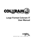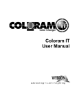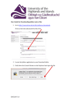
1
Models: 8670 TransitionTM Fiber-Optic Illuminator with CMY Color Mixing 8675 TransitionTM Fiber-Optic Illuminator with Twinkle Wheel 8677 TransitionTM Fiber-Optic Illuminator with Fixed Color Manual last revised June 2009 Table of Contents Declaration of Conformity...................................................................3 Safety Notice......................................................................................4 Introduction to Transition ...................................................................5 Quick Start..........................................................................................6 Specifications .....................................................................................7 Fixture Setup and Configuration ........................................................8 DMX/RDM Setup and Operation ........................................................10 Display Messages ..............................................................................11 Preparing the Plastic Fiber Bundle.....................................................13 Service ...............................................................................................18 Flash Reprogramming........................................................................20 Warranty Information..........................................................................21 Transition User Manual Revised March 2009 Page 2 Transition User Manual Revised March 2009 Page 3 Safety Notice SAVE THESE INSTRUCTIONS READ AND FOLLOW ALL INSTRUCTIONS This manual gives step-by-step instructions for preparation, setup, and operation of Wybron’s TransitionTM fiber-optic illuminator. There is a potential risk of fire, electric shock, or injury to persons if the product is not used as instructed. The Transition is to be used in an indoor environment only. WARNING: When using electrical appliances, use basic precautions, including: Read this manual before connecting power. Use supervision around children. Do not touch moving parts. Only use attachments recommended or sold by Wybron. Use in a dry location only. Product Modification Warning Wybron, Inc. products are designed and manufactured to meet the requirements of United States and International safety standards. Modifications to the products could affect safety and render the product non-compliant to relevant safety standards. Transition User Manual Revised March 2009 Page 4 Introduction Contained within a compact, easy-to-integrate package, the ultra-bright TransitionTM fiber-optic illuminator brings quality, durability, and exceptional color integration to installations requiring the best in fiber-optic lighting. The Transition produces a high lumen output with a CRI greater than 85 by using an efficient 150 UHI source. The UHI lamp has a rated life span of 10,000 hours, minimizing maintenance concerns. The precision-engineered lamp housing and reflector allow for lamp changes and no in-the-field lamp optimization. With its dichroic-coated borosilicate cold mirror reflector and hexagonal color integration element, the Transition isolates the fiber bundle from heat and UV radiation. The unit is engineered so that it will not burn PMMA fiber when correctly prepared (see page 13). The Transition features a color module capable of producing a nearly limitless palette of colors, letting users mix the perfect shade or hue with durable dichroiccoated borosilicate glass in cyan, magenta, and yellow. The colors won’t fade over time, and precise DMX control allows for smooth, subtle fades or instantaneous jumps to new colors. The Transition is controlled by four DMX channels: Cyan, Magenta, Yellow, and Dimmer. The unit is also compatible with the industry-standard feedback protocol Remote Device Management, or RDM, allowing it to work perfectly with Wybron’s Infotrace feedback system. Transition User Manual Revised March 2009 Page 5 Quick Start 1. Connect the Equipment A. Connect the fiber bundle common end to the Transition output port. B. Connect the Transition to a DMX source by using a 5-pin cable. C. Connect the unit to AC power (110 - 240 VAC 50/60Hz). 2. Control Transition with DMX A. With Transition addressed at channel 1 (factory default): B. DMX channel 1 controls Cyan (0% = no color, 100% = full saturation). C. DMX channel 2 controls Magenta (0% = no color, 100% = full saturation). D. DMX channel 3 controls Yellow (0% = no color, 100% = full saturation). E. DMX channel 4 controls Dimmer (0% = no output, 100% = full output). Note: On the Twinkle Wheel model, DMX channel 5 controls the Twinkle Wheel. 3. Control Transition using Demo Mode A. Press “Menu” until display reads dEn. B. Press “Enter” and display will read OFF. C. Press “ + ” or “ – “ to scroll through demo mode options. D. Press “Enter” at the desired demo mode. Transition will immediately begin executing the demo loop. Transition User Manual Revised March 2009 Page 6 Specifications Model 8670: Transition CMY Features: No lamp optimization required. Rubber feet for cabinet or countertop installation. Durable all-metal construction. Output supports fiber bundles ranging from 17mm to 30 mm diameter. High output 150W UHI compact arc source. Dimensions: Height: 7.750” Width: 5.625” Length (including fiber port): 13.500” Weight: 8.75 pounds Electrical Specifications: CAUTION: RISK OF FIRE Use MAX 150 watt, type M142 lamp. Power: 4A @110-120V ~ 50/60Hz or 2A @ 220-240V ~ 50-60Hz Isolate electrically before re-lamping. Environmental Specifications: Maximum Ambient Temperature: 40˚C / 104˚F. Maximum Exterior Surface Temperature: 90˚C / 194˚F. Minimum Air Space Sides: 2”. Minimum Air Space Top: 6”. CAUTION: Risk of exposure to ultraviolet (UV) radiation. Do not operate without complete lamp enclosure in place. Transition User Manual Revised March 2009 Page 7 Fixture Setup and Configuration Installing the Lamp DANGER: Disconnect fixture from line voltage before replacing lamp. CAUTION: Lamp and lamp mounting surfaces are hot! Allow lamp to cool 10 minutes before replacing. Lamp Specifications Lamp socket/base: G22 Part Number UHI-S150DW/A/UVP UHI-S150DM/A/UVP CDM150/T6/830 CDM150/T6/942 Lamp, Eurospot UHI Series 3000K 150W. Lamp, Eurospot UHI Series 4200K 150W. Lamp, CDM 150W with UV Fade Block 3000K. Lamp, CDM 150W with UV Fade Block 4200K. Disconnect fixture from AC power. Remove lamp plate by unscrewing mounting screws and pulling lamp assembly straight back from the illuminator. Grasping lamp by the base, remove old lamp from the socket. Insert new lamp into base. Lamp is fully seated when spring clips snap over lamp base. CAUTION: Touching the glass lamp envelope can reduce lamp life. Handle new lamps with a clean cloth. Fingerprints can be cleaned off the lamp envelope with alcohol and a clean cloth. Locating the Fixture The Transition can be surface-mounted, located in a cabinet or closet, or hung from a mounting pipe with the optional pipe bracket. Surface Mounting The Transition may be surface mounted on a hard surface table, counter top, or floor (wood, laminate, metal, tile). Do not mount the Transition on soft surfaces such as carpet, linoleum, cushions, or fabric. Maximum ambient temperature (ta) may not exceed 40˚C Transition User Manual Revised March 2009 Page 8 (104˚F). Keep objects at least 2” (50 mm) from the sides of the fixture. Keep objects at least 6” from the top of the fixture. Cabinet or Closet Mounting The Transition may be mounted in a closet or cabinet on a hard surface such as wood, laminate, or metal. Do not mount the Transition on soft surfaces such as linoleum or fabric. Maximum ambient temperature (ta) may not exceed 40˚C (104˚F). Keep objects at least 2” (50mm) from sides of the fixture. Keep objects at least 6” from the top of the fixture. Pipe mounting The Transition may be pipe-mounted using the optional pipe mount bracket. See diagram for acceptable pipe mounting orientations. Connecting Fiber Common End Connecting fiber to the illuminator is as simple as inserting the fiber bundle common end into the mounting port and tightening the set screw. The Transition works with fiber common end bundles with clear apertures ranging from 17mm to 32mm in diameter. The mounting port is can be changed to match the type of fiber bundle ferrule being used. Consult the factory regarding the correct mounting port to be used in your application. Connecting AC Power CAUTION: Be sure the fixture is properly grounded. The user should ensure that a good source of AC power is available that complies with local building and electrical codes and has both overload and ground fault protection. Use only 18/3, type IEC power cord. Input power must be 110 – 240VAC, 50/60Hz. Transition User Manual Revised March 2009 Page 9 DMX / RDM Setup and Operation Controls and Indicators Transition controls and indicators are as follows: o A three-character seven-segment display. o Four push buttons: Menu, (+), (-), and Enter. o Power (red) and signal (green) indicator LEDs. The seven-segment display shows the address number (1-508) and the Demo mode (OFF, d1, d2). It also displays any error messages that are covered in the service section of the manual. The Menu button allows you to switch between address and demo mode selection. The (+) button allows you to increment Transition’s DMX address when in the address mode or select between Demo 1 (d1), Demo 2 (d2), and Demo Off / DMX control (OFF) in demo mode selection. The (-) button allows you to decrement Transition’s DMX address when in address mode, or select between Demo 1 (d1), Demo 2 (d2), and Demo Off / DMX control (OFF) in demo mode selection. The Enter button allows you to accept the mode or address currently displayed. Changes are saved in non-volatile memory when the Enter button is pressed. The red power indicator LED remains lit when the device is powered. The green signal indicator LED flashes when a DMX or DMX/RDM signal is present. It turns off 60 seconds after the last button press. Transition User Manual Revised March 2009 Page 10 Display Messages Normal Messages 680 Ini Displayed for 1 second after power is applied. This is the RDM manufacturer device identification number. Indicates that the unit is initializing the dichroic filters. 001 – 508 The first DMX address to which Transition will respond. Adr Top menu item. Pressing Enter here will allow the current DMX address to be changed. DEn Top menu item. Pressing Enter here will allow the current DMX control/demo control state to be changed. OFF Demo modes are off. Transition will respond to DMX commands. d1 Transition will execute demo loop 1 commands. d2 Transition will execute demo loop 2 commands. Blank Unit is running, no error conditions exist, and it has been longer than 60 seconds since the last button press. Error Messages (Flashing) Er1 Indicates motor 1 has encountered an error and stopped moving. Er2 Indicates motor 2 has encountered an error and stopped moving. Er3 Indicates motor 3 has encountered an error and stopped moving. Er4 Indicates motor 4 has encountered an error and stopped moving. Lo DC Supply voltage has dropped below 17 volts. The unit will stop Transition User Manual Revised March 2009 Page 11 operation at 16 volts. EEP Err An attempt to write to non-volatile memory has failed. The unit will continue to respond to commands. SEr Err The RDM unique ID has been corrupted. The unit will operate normally but should not be used in an RDM environment. Contact dealer or factory for assistance. RDM Functionality Transition is compliant with the RDM v1.0 standard and can be used with the Wybron Infotrace system or other RDM systems. By definition, all required RDM parameters are supported, including, discovery, device info, DMX start address, identify device, etc. Additional RDM functions supported include: • Status and queued messages – this allows the device to let the controller know it has something to say. • Device model description – gives the controller a readable description of the Transition. • Manufacturer label. • Device label – user-definable field up to 32 characters allowing the user to give it a meaningful name in the particular application, such as “Star curtain 2” or “Shark display upper right.” • Software version information. • DMX personality – the Transition personalities include DMX control, demo mode 1, and demo mode 2. • DMX start address – this can be set remotely through an RDM system. • Slot description – human readable explanation of the function of each of the Transition’s DMX channels. • Sensor information including operating voltage and voltage history. • Device operational hours. • Remote device reset. Transition User Manual Revised March 2009 Page 12 Preparing the Plastic Fiber Bundle The Transition fiber illuminator features a highly efficient optical system producing high-intensity visible output at the common end of a fiber bundle. Figure 1 shows the spectral energy distribution at the output port of a Transition fiber illuminator. Of the total radiated energy, 98.27% falls within the visible band, 0.95% in UV, and 0.78% in IR. While virtually all of the radiated energy lies within the visible band, care must still be exercised when using plastic fiber because of the high energy/area at the fixture’s output port. This energy must be transmitted through the fiber instead of being converted to heat at the face of the fiber bundle. Transition Spectrum 4000 3500 Relative Intensity 3000 2500 2000 1500 1000 500 0 350 400 450 500 550 600 650 700 750 800 850 900 950 1000 Wavelength (nm) Intensity UV border IR border Figure 1 Light energy turns into heat in the fiber bundle when it’s absorbed by contaminants on and around the fibers or when the fiber material absorbs scattered light. Contaminants could be powders used to minimize friction between individual fibers within a jacketed bundle, dirt particles, accumulated dust from a cooling fan, and more. Unpolished fiber causes light to scatter at the input side of the fiber bundle. The scattered light refracts and reflects in the vicinity of the common end until the fiber or the common-end ferrule absorbs it. Both contaminants and fiber-end surface roughness must be minimized before using the fiber with a high-intensity fiber illuminator. The following procedure details the steps necessary to prepare a fiber bundle for use with the Transition. If you are starting with a bundle that appears to be finished as well as the one shown in Figure 7, you can begin at the Testing section. Transition User Manual Revised March 2009 Page 13 Procedure 1. Begin with the raw common end. Figure 2 2. Pull the fiber through to allow better access for cleaning. Figure 3 Transition User Manual Revised March 2009 Page 14 3. Using water, rinse any dirt or particles from the extended fiber, then allow the bundle to air dry (or use compressed air). Figure 4 4. Pull the fiber bundle back into the ferrule (to minimize waste) and trim it with a hot knife. Figure 5 Transition User Manual Revised March 2009 Page 15 5. Sand the fibers flush with the ferrule using 150- or 220-grit sandpaper. Figure 6 6. Sand the face with 400- and 1000-grit sandpaper and finish with 3µm polishing film or rubbing compound. The face must have a glass-like finish. Figure 7 Transition User Manual Revised March 2009 Page 16 Testing Following Table 1, insert the finished fiber bundle into the Transition output port. Ferrule I.D. Insertion depth (mm) (in.) 30 0.75 28 0.85 26 0.96 24 1.06 22 1.17 20 1.27 18 or smaller Fully inserted Table 1 Start the Transition and allow it to run for 15 minutes. Then remove the fiber and check for deformation on the input face of the bundle. If there is no damage, repeat the test in one-hour and four-hour increments. A bundle that shows no sign of deformation after the four-hour test will perform well indefinitely. If the fiber face shows only slight damage, the fiber can usually be pushed back through the front of the common-end ferrule, cleaned, and then pulled back flush with the ferrule without having to re-sand or re-polish it. If the fiber face shows more extensive damage, repeat steps two through seven. Transition User Manual Revised March 2009 Page 17 Service Lamp Replacement DANGER: Disconnect fixture from line voltage before replacing lamp. WARNING: Lamp and lamp mounting surfaces are hot! Allow lamp to cool before replacing. Disconnect fixture from AC power. Remove lamp plate by removing mounting screws and pull lamp assembly straight back from reflector. Grasping lamp by the base, remove the old lamp from the socket. CAUTION: Touching the glass lamp envelope can reduce lamp life. Handle new lamps with a clean cloth. Fingerprints can be cleaned off lamp envelope with alcohol and a clean cloth. Insert new lamp into base. Lamp is fully seated when spring clips snap over lamp base. Cleaning the Reflector WARNING: To avoid burns or damage to the fixture, allow fixture to cool before cleaning. Remove Transition lid. Remove lamp plate by removing mounting screws and pulling lamp assembly straight back from reflector. Remove top two reflector mount screws and washers. Lift reflector up and back to remove from fixture. Use clean pressurized air or a soft cloth with alcohol to clean the reflective surface. Reseat the reflector and secure in place by replacing the top screws and washers. Replace lamp plate and lid. CAUTION: Harsh chemicals and rough cloth can damage the cold mirror coating on the reflector. Be sure to replace damaged reflectors. Transition User Manual Revised March 2009 Page 18 Cleaning the Color Filters It is recommended that the color filters only be cleaned with low-pressure air without disassembling the color filters from the motor shafts. If the color module must be disassembled to clean the dichroic filters, take careful note of the location and offset height of the individual color flags. Color filters must be reassembled in exactly the same orientation and correct heights to ensure proper operation! CAUTION: Dichroic filters are easy to break! Support the glass from the behind when cleaning the surface. Remove cover. Remove four screws holding color filter plate into the chassis. Holding glass hex rod, slide the motor plate back toward the reflector and then up out of the chassis after it is clear of the rod. Noting filter location and height, loosen hub setscrew and slide filter and hub from motor shaft. Reverse previous operation to reassemble color module. Cleaning the Hex Integration Rod Initialize unit, command flags to open white positions, and power down. Allow unit to cool. Disconnect fiber bundle from output port. Remove cover. Clean rod sides and ends with window cleaner. Reassemble cover and fiber bundle. Transition User Manual Revised March 2009 Page 19 Flash Reprogramming Transition firmware can be updated through the DMX/RDM port as new firmware versions become available. The updates are transmitted via the Infogate – the RDM gateway at the heart of Wybron’s Infotrace feedback system. For Transition firmware updates, visit www.wybron.com. Specific instructions for upgrading firmware in Transition and other Wybron equipment can be found in the Firmware Upgrades section of the Infogate user manual. Transition User Manual Revised March 2009 Page 20 Warranty Information WYBRON, INC. warrants to the original owner or retail customer that for a period of one year from date of delivery of a portable system or energization of a permanently installed system (up to a maximum of 18 months from delivery) its products will be free from defects in materials and workmanship under normal use and service. Warranty does not cover any product or part of a product subject to accident, negligence, alteration, abuse, misuse or any accessories or parts not supplied by WYBRON, INC. Warranty does not cover "consumable" parts such as fuses, lamps, or color media. WYBRON INC.'s warranty does not extend to items not manufactured by us. Freight terms on warranty repairs are FOB WYBRON, INC. factory or designated repair facility. Collect shipments or freight allowances will not be accepted. WYBRON, INC.'s sole responsibility under this warranty shall be to repair or replace at WYBRON, INC.'s option such parts as shall be determined to be defected on WYBRON, INC.'s inspection. WYBRON, INC. will not assume any responsibility for any labor expended or materials used to repair any equipment without WYBRON, INC.'s prior written authorization. WYBRON, INC. shall not be responsible for any incidental, general or consequential damages to property, damages for loss of use, time, profits or income, or any other charges. The owner's obligations during the warranty period under this warranty are to notify WYBRON, INC. at WYBRON, INC.'s address within one week of any suspected defect, and return the goods prepaid to WYBRON, INC. at their factory or authorized service center. This warranty is contingent on the customer's full and timely compliance with the terms of payment set forth in said purchase order. This warranty is expressly in lieu of any and all other warranties expressed or implied including the warranties of merchantability and fitness for a particular purpose and of other obligations and liabilities on our part. The owner acknowledges that no other representations were made to him or relied upon him with respect to the quality and function of the goods sold. This written warranty is intended as a complete and exclusive statement of the terms thereof. Prior dealings or trade usage shall not be relevant to modify, explain or vary this warranty. Acceptance of, or acquiescing in, a course of performance under this warranty shall not modify the meaning of this agreement even though either party has knowledge of the performance and a chance to object. Transition User Manual Revised March 2009 Page 21