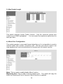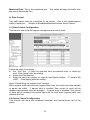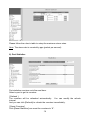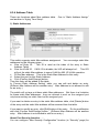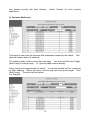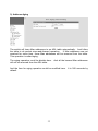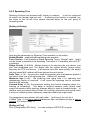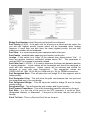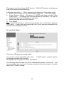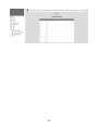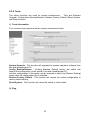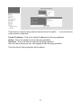
1
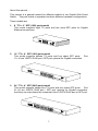
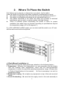
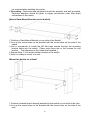
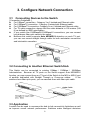
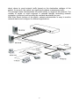
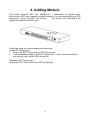
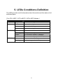
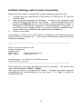
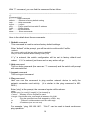
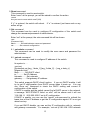
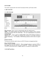
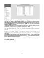
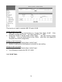
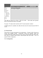
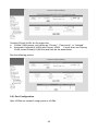
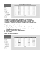
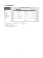
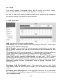
Gigabit Web Smart Switch
User's Manual
Rev. 1.21c-EV
1
We make no warranties with respect to this documentation and disclaim any
implied warranties of merchantability, quality, or fitness for any particular purpose.
The information in this document is subject to change without notice. We
reserve the right to make revisions to this publication without obligation to notify
any person or entity of any such changes.
Trademarks or brand names mentioned herein are trademarks or registered
trademarks of their respective companies.
2
About this manual …
This manual is a general manual for different models of our Gigabit Web Smart
Switch. They are similar in operation but have different hardware configurations.
These models are
1.
8 * TX + 2 * SFP (10G) ports model
This model supports eight TX ports and two extra SFP ports for Gigabit
Ethernet connections.
2.
16 * TX + 4 * SFP (16G) ports model
This model supports sixteen TX ports and four share SFP ports.
Port
13~16 are 1000TX RJ45 port / SFP port optional for Gigabit connection.
3.
24 * TX + 4 * SFP (24G) ports model
This model supports twenty-four TX ports and four share SFP ports.
Port
21~24 are 1000TX RJ45 port / SFP port optional for Gigabit connection.
And they can auto-detect the connection from 1000TX RJ45 port or SFP port.
3
Contents
1. INTRODUCTION ...............................................................................................2
1.1 PACKAGE CONTENTS ......................................................................................2
2. WHERE TO PLACE THE SWITCH ...................................................................3
3. CONFIGURE NETWORK CONNECTION.........................................................6
3.1 CONNECTING DEVICES TO THE SWITCH .............................................................6
3.2 CONNECTING TO ANOTHER ETHERNET SWITCH/HUB .........................................6
3.3 APPLICATION ..................................................................................................6
4. ADDING MODULE ............................................................................................8
5. LEDS CONDITIONS DEFINITION ....................................................................9
6. MANAGE / CONFIGURE THE SWITCH .........................................................10
6.1 INTRODUCTION OF THE MANAGEMENT FUNCTIONS .............................................10
6.2 BASIC SETTINGS WITH CONSOLE CONNECTION ................................................13
6.3 MANAGEMENT WITH HTTP CONNECTION ..........................................................17
6.3.1 System ................................................................................................18
6.3.2 Security .............................................................................................22
6.3.3 Port .....................................................................................................26
6.3.4 Address Table.....................................................................................31
6.3.5 Spanning Tree ....................................................................................34
6.3.6 VLAN ..................................................................................................36
6.3.7 QoS.....................................................................................................43
6.3.8 Trunk...................................................................................................47
6.3.9 Tools ...................................................................................................50
7. SOFTWARE UPDATE AND BACKUP ............................................................52
A.
PRODUCT SPECIFICATIONS .....................................................................53
B.
COMPLIANCES ...........................................................................................56
C.
WARRANTY .................................................................................................57
1.
Introduction
There are three models for the Gigabit Web Smart Switch Series –
8TX+2SFP(10G) model, 16TX+4SFP(16G) model and 24TX+4SFP(24G) model.
This Gigabit Web Smart Switch is a Layer2 Web Smart switch with lots of
advanced network functions including VLAN, trunking, spanning tree, mirror port,
rate limit and port configuration. Console is supported for some basic settings.
Web interface is for switch management. IEEE 802.1x is supported for port
security application. These functions can meet most of the management request
for current network.
1.1 Package Contents
z
z
z
z
z
One Gigabit Web Smart Switch
One AC power cord
One console cable
Two rack-mount kits and screws (*for 16TX+4SFP/24TX+4SFP models
only)
This user's manual
2
2.
Where To Place the Switch
This Switch can be placed on a flat surface (your desk, shelf or table).
Place the Switch at a location with these connection considerations in mind:
z
The switch configuration does not break the rules as specified in Section 3.
z
The switch is accessible and cables can be connected easily to it.
z
The cables connected to the switch are away from sources of electrical
interference such as radio, computer monitor, and light fixtures.
z
There is sufficient space surrounding the switch to allow for proper
ventilation (the switch may not function according to specifications beyond
the temperature range of 0 to 50 degrees C).
For 16TX+2SFP/24TX+4SFP model, you can also install the switch on a 19" rack
with the rack-mount kits as the picture.
<< Rack-Mount Installation >>
Before rack mounting the switch,please pay attention to the following factors :
1. Temperature - Because the temperature in a rack assembly could be higher
than the ambient room temperature, check that the rack-environment
temperature is within the specified operating temperature range. (Please refer
to Product Specifications in the manual.) Air flow is necessary in a rack for
temperature stable.
2. Mechanical Loading - Do not place any equipment on top of this rack-mounted
switch.
3. Circuit Overloading - Be sure that the supply circuit to the rack assembly is
3
not overload after installing this switch.
4. Grounding - Rack-mounted equipment should be properly and well grounded.
Particular attention should be given to supply connections other than direct
connections to the mains.
[Attach Rack-Mount Brackets to the Switch]
1. Position a Rack-Mount Bracket on one side of the Switch.
2. Line up the screw holes on the bracket with the screw holes on the side of the
switch.
3. Use a screwdriver to install the M3 flat head screws through the mounting
bracket holes into the switch. (There could have two or four screws for one
bracket. That depends on the model that installed.)
4. Repeat Step 1~3 to install another bracket to the switch.
5. Now it is ready to mount to a rack.
[Mount the Switch on a Rack]
1. Position a bracket that is already attached to the switch on one side of the rack.
2. Line up the screw holes on the bracket with the screw holes on the side of the
rack.
4
3. Use a screwdriver to install the rack screws through the mounting bracket holes
into the rack.
4. Repeat Step 1~3 to attach another bracket that is already attached to the switch
on another side of the rack.
5
3. Configure Network Connection
3.1 Connecting Devices to the Switch
[ Connection Guidelines: ]
z
For 10BaseT connection : Category 3 or 5 twisted-pair Ethernet cable
z
For 100BaseTX connection : Category 5 twisted-pair Ethernet cable
z
For 1000BaseTX connection: Category 5e or 6 twisted-pair Ethernet cable
z
For TX cable connection, always limit the cable distance to 100 meters (328
ft) as defined by IEEE specification
z
If your switch has 1000BaseSX/1000BaseLX connections, you can connect
long distance fiber optic cable to the switch.
z
Because this switch supports Auto MDI/MDI-X detection on each TX port,
you can use normal straight through cable for both workstation connection
and hub/switch cascading.
3.2 Connecting to Another Ethernet Switch/Hub
This Switch can be connected to existing 10Mbps / 100Mbps / 1000Mbps
hubs/switches. Because all TX ports on the Switch support Auto MDI/MDI-X
function, you can connect from any TX port of the Switch to the MDI or MDI-X port
of another hub/switch with Straight Through or Crossover cables.
If the
switches have fiber-optic ports, you can cascade them with fiber optic cable.
3.3 Application
A switch can be used to overcome the hub-to-hub connectivity limitations as well
as improve overall network performance. Switches make intelligent decisions
6
about where to send network traffic based on the destination address of the
packet. As a result, the switch can significantly reduce unnecessary traffic.
The example below demonstrates the switch ability to segment the network. The
number of nodes on each segment is reduced thereby minimizing network
contention (collisions) and boosting the available bandwidth per port.
With Web Smart function of the switch, network administrator is easy to monitor
network status and configure for different applications.
7
4. Adding Module
This switch supports SFP (for 1000SX/LX/…) connectors for gigabit ports.
Because the SFP slots support hot-swap function, you can plug/unplug the SFP
transceiver to/from the SFP slot directly.
The switch can auto-detect the
gigabit connection from SFP slot.
Follow the steps for module adding and removing.
[ Add SFP Transceiver ]
1. Plug in the SFP Transceiver to SFP slot directly.
2. Connect network cable to the SFP Transceiver. If the connected devices
are working, the Link/Act LED will be ON.
[ Remove SFP Transceiver ]
Unplug the SFP Transceiver from SFP slot directly.
8
5. LEDs Conditions Definition
The LEDs provide useful information about the switch and the status of all
individual ports.
[ For 8TX+2SFP / 16TX+4SFP / 24TX+4SFP Models ]
LED
Power
STATUS
ON
CONDITION
Switch is receiving power.
System
OFF
System is booting.
Yellow
System is initializing.
Green
System is running.
ON
Port has established a valid link.
Flashing
Data packets being received or sent.
Green
The connection speed is 1000Mbps.
Link / Act
FDX/Col.
Yellow
The connection speed is 10/100Mbps.
ON
The connection is Full Duplex.
Flashing
Collisions happen for Half Duplex.
9
6. Manage / Configure the switch
6.1 Introduction of the management functions
This switch is a L2 Web Smart switch. It supports in-band management function
from Http interface. Console is supported for some basic settings.
It
supports network configuration functions, like VLAN, Trunking, Port Mirror, QoS,
spanning tree and software backup/update.
Users can configuration these
functions for different network applications.
The following is a brief introduction
about these functions before the detail operation sections.
1. VLAN (Virtual LAN)
VLAN can divide the switch to several broadcast domains to prevent network
traffic between different user groups. This switch supports 802.1Q tag-based
VLAN and Port-based VLAN. Users with the same VLAN ID can transfer data
to each other. The network traffic will be blocked if they have different VLAN ID.
2. Trunk
If two switches are cascaded together, the bottleneck will happen at the
cascading connection.
If more cables could be used for the cascading
connection, it will reduce the bottleneck problem.
In normal case, switches
will become unstable because of traffic looping when more than one cable is
connected between them.
If the switches support trunk function, they can
treat these cables as one connection between them. The traffic looping will not
happen between these cables and the switches will work stable with bigger
bandwidth between them.
Notes: About redundant application
The trunk connection supports redundant function. If any trunk cable is
broken, the traffic going through that cable will be transferred to another trunk
cable automatically. For example, if traffic of user port Port 6 is assigned to
Port 1 in a Trunk and Port 1 connection breaks, Port 2 will take over the traffic
for Port 6 automatically. (It could be used for redundant application.)
3. Spanning Tree Protocol / Rapid Spanning Tree Protocol
Spanning tree is a protocol to prevent network loop in network topology. If
network loop happens, it will cause switches in the network unstable because
more and more traffic will loop in the network.
If network loop happens,
spanning tree protocol will block one connection in the loop automatically.
But it will also cause a period of delay (30 seconds for STP and shorter time for
RSTP) if any network connection is changed because of the network topology
detection operation of the protocol.
Because there could be more than one switch in the network, users can
configure this function for their network spanning tree application.
4. Port Mirror
This switch operates in store-and-forward algorithm so it is not possible to
10
monitor network traffic from another connection port. But the port mirror
function can copy packets from some monitored port to another port for network
monitor.
5. QoS
For Quality of Service request in a network, packets could be classified to
different forwarding priorities. For real-time network traffic (like video, audio),
it needs higher priority than normal network traffic.
With the definition of
packet priority, it could have 8 priority levels (from 0 to 7).
This switch
supports four priority level queues on each port. It could be configured for
port-based, 802.1P tagged based, or DiffServ of IP packets priority. User can
define the mapping of priority values to the priority queues.
6. Static Mac ID in ARL table
The switch can learn the Mac address from user’s packets and keep these Mac
address in the ARL table for store-and-forward table lookup operation. But
these Mac addresses will be deleted from ARL table after some time when
users do not send any packets to the switch. This operation is called aging
and the time is called aging time. It is about 5 minutes normally (it could be
changed by users.) If users want to keep a Mac address always in ARL table
on some port, they can assign the Mac address to ARL table. These Mac ID
are called Static Mac address.
This switch supports static Mac address
assignment.
The static Mac address assignment will also limit the Mac
address could be used on the assigned port only with the port security
configuration function. For example, assigning “00-00-e2-11-22-33” to Port 5
will always keep this Mac ID alive on Port 5 but also limit this Mac address could
work on Port 5 only.
Note: About Static Mac Address Filter-in (port binding) function
There is a “Mac Security Configuration” function for port security.
If it is set to
“Accept function”, only these static Mac addresses can access network through
the assigned port.
The other Mac addresses will be forbidden for network
access through that port. This function can be used for port binding security
application. Please refer to Section 6.3 for the details of the Mac address filterin operation of the switch.
7. Dynamic Mac ID Number Limit
Beside Static Mac ID Limit, there is another Dynamic Mac ID Number Limit
function for Mac address security on port. This function can limit the Mac ID
number to access network through a port. For example, five Mac ID are
allowed for Port 2. That means up to five users are allowed, but don’t care
who the users are. It is done by “Limit by Mac no.” option in “Mac Security
Configuration” function.
8. IEEE 802.1x Port Security Function
If the 802.1x function is enabled, the switch will act as an authenticator for
users accessing network through the switch.
It will need a RADIUS server for
the authentication function. Users will be asked for username and password
before network access. If the RADIUS server authenticates it, the switch will
11
enable the port for network access.
This function is very useful for network
security application to prevent illegal users access network through the switch.
9. Rate Control
This function can limit the traffic rate for physical ports. The traffic could be
ingress traffic or egress traffic.
This function can limit the network bandwidth
utilization of users.
10. Private VLAN
Three kinds of VLAN are defined for this application – Primary VLAN,
Community VLAN, and Isolated VLAN. Community VLAN and Isolated VLAN
can communicate with Primary VLAN, but they cannot communicate with each
other. And users in Isolated VLAN cannot communicate with each other. This
is a special VLAN configuration. This switch supports a dedicated configure
interface for such application.
11. Software Backup/Update
This switch supports backup and update functions for its internal software and
its network configuration. It could be done in two ways.
a. From console when booting : doing by Xmodem protocol and by terminal
program for boot code and run-time code updating..
b. From web browser : doing by http protocol and by web browser for run-time
code and configuration backup/update.
12
6.2 Basic Settings with Console Connection
Please follow the steps to complete the console hardware connection first.
1.
Connect from the console port of the switch to COM port of PC with the
console cable.
2.
Start the terminal program of Windows. Create a new connection and
select COM port of PC used for the console. Set the configuration of the
terminal as [9600,8,N,1]. (You can find the terminal program in [Start] ->
[Programs] -> [Accessory Programs] -> [Communication] -> [Terminal]. If
you cannot find it, please install it from your Windows Installation Disk.
Please refer to your Windows user manual for the installation.)
3.
Power on the switch.
If everything is correct, the booting screen will appear in the terminal program
when the switch is powered on. It will stop at the following screen after some
initializing messages.
------------------------------------------------------------------------------------------------------......
Start to run system initialization task.
[System Configuration]
Company Name
:
Model Name
: Gigabit Web Smart Switch
MAC Address
: 00:00:00:01:53:47
Firmware version: 1.01.04 (built at Jul 15 2008 09:19:16)
Press <ENTER> key to start.
------------------------------------------------------------------------------------------------------Press Enter key, user name and password will be requested. The default user
name and password is "admin" / ”admin”.
After login the switch, a prompt will be shown. Because this switch supports
command-line for console interface, you can press “?” or “help” to check the
command list first.
13
With “?” command, you can find the command list as follow.
------------------------------------------------------------------------------------------------------>?
[Command List]
?.............. Help commands
default........ Restore to factory default setting
help........... Help commands
logout......... Logout
ping........... Ping a specified host with IP address
reset.......... Reset system
set............ Set commands
show........... Show commands
------------------------------------------------------------------------------------------------------Here is the detail about these commands.
1. Default command
This command is used to restore factory default settings.
Enter “default” at the prompt, you will be ask to confirm with Yes/No.
>default
All current setting will be lost after restoring default!
Are you sure to restore default setting now?(Y/N)
If “y” is entered, the switch configuration will be set to factory default and
reboot. If “n” is entered, just leave and no any action will go.
2. Help command
This is a help command (the same as “?” command) and the switch will prompt
with command list.
3. Logout command
This is a logout command.
4. Ping command
User can use this command to ping another network device to verify the
network connection and activity. (It is similar to the ping command in MSDOS.)
Enter “ping” at the prompt, the command syntax will be shown.
>ping
Syntax: ping [-n count] [-l length] [-t] [-w timeout] ip
-n count : Number of echo requests to send.
-l length : Send buffer size, and length is between 64~8148
-t
: Ping the specified host until stopped by <ESC> key.
-w
: Timeout in milliseconds to wait for each reply.
ip
: IP address (xxx.xxx.xxx.xxx)
For example, “ping 192.168.1.80”. “Ctrl-C” can be used to break continuous
ping operation.
14
5. Reset command
This command is used to reset switch.
Enter “reset” at the prompt, you will be asked to confirm the action.
>reset
Are you sure to reset switch now?(Y/N)
If “y” is entered, the switch will reboot. If “n” is entered, just leave and no any
action will go.
6. Set command
This command can be used to configure IP configuration of the switch and
change the username/password of administrator.
Enter “set” at the prompt, the sub-command list will be shown.
>set
[Command List]
admin.......... Set administrator name and password
net............ Set network configuration
6.1 set admin command
This command can be used to modify the user name and password for
administrator.
6.2 set net command
This command is used to configure IP address of the switch.
Its syntax is . . .
>set net
[Syntax]set net [arg_1 data_1] [arg_2 data_2] ... [arg_n data_n]
[Argument List]
dhcp........... Set DHCP client
ip............. Set IP Address
netmask........ Set netmask
gateway........ Set gateway IP address
This switch supports DHCP client function. If you set DHCP enable, it will
try to get IP configuration from DHCP server when it boots up. You can
use “show net” command to check the DHCP setting and current IP
configuration of the switch.
If DHCP is enable and the switch cannot find a DHCP server in the network,
a message “BOOTP/DHCP failed on eth0” will be shown and it will use
“192.168.1.1 / 255.255.255.0” as its IP configuration.
If DHCP is enable, you can use the “renew” sub-command to refresh the
lease time of the IP address or get the IP configuration again if IP is not got
when boot-up.
If you set DHCP disable, you can set the IP configuration with ip, netmask
and gateway commands. For example, “set net ip 192.168.1.250 netmask
15
255.255.255.0 gateway 192.168.1.154” will set these parameters as the IP
address configuration of the switch.
After the command, you can use
“show net” to verify the setting.
7. Show command
This command is used to show IP configurations of the switch.
>show
[Command List]
net............ Show network configuration
7.1 show net command will show current IP address configuration of the
switch. For example,
>show net
[eth0] Network Configuration:
DHCP
: DISABLE
IP Address: 192.168.1.12
Netmask : 255.255.255.0
Gateway : 192.168.1.2
Note: the default IP configuration of the switch is ...
DHCP
: DISABLE
IP Address: 192.168.1.1
Netmask : 255.255.255.0
Gateway : 192.168.1.254
16
6.3 Management with Http Connection
Users can manage the switch with Http Web Browser connection. Before http
connection, IP address configuration of the switch should be done first.
Please follow the instruction in Section 6.2 to complete the console connection
and use “show net” command to check IP address of the switch first. If users
want to change the IP address of the switch, use “set net ip xxx.xxx.xxx.xxx
netmask xxx.xxx.xxx.xxx gateway xxx.xxx.xxx.xxx” command to modify the IP
address of the switch. The default IP configuration is 192.168.1.1, mask
255.255.255.0 and gateway 192.168.1.254.
After IP address configuration done and the switch is connected to network, users
can start Http connection by entering IP address of the switch to the web address
line in Web Browser.
A login screen will be prompted for user name and
password. The default user name and password is "admin" / ”admin”. Then
the management homepage will appear.
Left part of the homepage is a function list. Users can select one of them for
status monitoring or switch configuration.
Upper part of the homepage is the link status of the switch. Three different
colors are used to show different status of ports – Link Up, Link Down and Port
Disable.
Middle part of homepage is the main operation area for each function.
The details about management with http connection will be shown in the following
sub-sections.
17
6.3.1 System
“System Information” is the homepage of the switch.
functions for it.
And there are four sub-
1). System Information
This function lists the system information about the switch. You can find the
firmware version, Mac address, connection port number, and maximum VLAN
group number here.
2). IP Configuration
This function is used to setup the IP configuration of the switch.
You can enable DHCP client function to get IP configuration from DHCP server
automatically.
Or, disable DHCP client function and set IP configuration
manually.
Management VLAN : This is used to setup the VLAN ID for remote management
18
interface of the switch. Only users in the same VLAN can manage the switch
remotely.
For example, setting it to “5” will allow the users in the VLAN with
VLAN ID 5 to manage the switch remotely. It works only 802.1Q VLAN function
is enable. And please don’t use Community VLAN and Isolated VLAN of Private
VLAN as management VLAN. It is caused by the limitation of Private VLAN
function.
About DHCP Client [renew] and [release] button ...
[renew] button: If DHCP client function is enabled, you can click [renew] button to
refresh the lease time of the IP address. If IP configuration is not got when bootup, clicking [renew] button will try to get IP configuration again.
[release] button: If DHCP client function is enabled and IP configuration is got,
clicking [release] button will release current IP configuration. After that, you can
click [renew] button to get the IP configuration again.
3). Time Configuration
There are two ways to get the system time.
a). Get time from Time Server
This switch support NTP protocol to get time from Internet time server. For such
application, you have to select “Get Time by Time Server”, input the IP of Time
Server, and select the Time Zone of your location. Then click [Apply]
If time is got from Time Server, it will be shown at “Current Time”.
For such application, you have to get the IP of Time Server from your network
administrator first.
b). Set time manually
This switch can count time internal. You can select “Get Time by Manually”, and
input current time manually. Then click [Apply].
4). Log
19
[Configuration]
Users can configure System Log function and view log records here. If this
function is enabled, the switch will record events to a log file and put the log file to
flash.
Up to 512 records are allowed for local logging.
If more than 512 events
happen, the records will be overwritten from beginning.
And if remote
syslog server is applied, the switch will also send event record to the syslog
server.
About log function configuration ...
System Log Status : This can enable/disable system logging function.
Log Level (0~7) : Log levels 0~7 are defined ad below.
Level
Name
Description
0
Emergency
System is unusable
1
Alert
Action must be taken immediately
2
Critical
Critical conditions
3
Error
Error conditions
4
Warning
Warning conditions
5
Notice
Normal but significant condition
6
Informational
Informational messages
7
Debug
Debug-level messages
Remote Log : This can enable/disable remote syslog function.
Remote Log Server IP : This is the syslog server IP for remote logging. Up to
five syslog servers is supported. Event logs will be sent to those syslog servers
at the same time.
[ Log Table ]
20
You can view log content here. There could be more than one page. You may
change the page or go to a page by its operation icons.
Clicking [clear log] button will clear the local log table.
21
6.3.2 Security
This function is used to configure security functions of the switch. Those security
functions are Administrator Management Security, Mac ID Access Security, and
802.1x Authentication Security.
1). User Accounts (Administrator Management Security)
Administrator Username/Password : This is for network administrator to
change his/her username and password. (Default is admin/admin.)
Guest Username/Password : This is used to setup the username/password of
guest-right user who just can view the setting of the switch.
[Security Policy]
This is used to setup the IP addresses that can manage this switch. They have
different access rights set in “Mode”. And the remote management interfaces
22
(Http) could be enable/disable for different administrators. This is for security
policy for switch management.
Note: Remember to enable at least one IP/Subnet with Modify right for Http
interface. Otherwise, configuring switch from remote will become impossible.
In that case, you have to use the “default” command from console to restore
settings to factory default for switch management.
2). Mac Security Configuration
There two Mac ID security modes for the switch.
One is Static Mac ID Filter on
Port, another is Dynamic Mac ID Number Limit on Port.
[ Static Mac ID Filetr on Port ]
This function can limit only those static Mac addresses on the port can access
network. Other Mac addresses will be rejected by the port. Sometimes it is
called “Mac-Port Binding”.
Follow the steps to configure it.
a. Set the “Security Control” to “Accept” on those ports that will apply static Mac
ID security.
Then click [Apply].
b. Set Static Mac Addresses that are allowed for network access at [Static
Address] of [Address Table] function.
Please refer to that section for the
details.
[ Dynamic Mac ID Number Limit on Port ]
This function can limit the Mac ID number to access network through a port. For
example, five Mac ID are allowed for Port 2. That means up to five users are
allowed, but don’t care who the users are.
Follow the steps to configure it.
a. Set the “Security Control” to “Limited by MAC no.” on those ports that will
apply dynamic Mac ID number security. And set the “Max. MAC no.” to the
users number allowed on the ports.
23
b.
Then click [Apply].
The switch will learn users automatically and show current user number at
“Learned no.”.
3). 802.1x Configuration
If 802.1x function is enabled, the switch will act as an authenticator for users
accessing network through the switch. It will need a RADIUS server for the
authentication function.
Users will be asked for username and password before
network access. If the RADIUS server authenticates it, the switch will enable the
port for network access.
This function is very useful for network security
application to prevent illegal users access network through the switch.
The function here is for 802.1x function configuration.
1. 802.1x Authentication Status: [Enable/Disable/Transparent]
Enable: enable 802.1x function in authentication mode
Disable: disable 802.1x function
Transparent: only forwarding 802.1x packets
2. Re-authentication (enable/disable), Timeout Period and Max Count:
The re-authentication function will re-authenticate users after the timeout
period. The Max Count is the maximum re-try count between the switch and
users before authentication fail.
3. Max Request Count and Server Timeout Period:
The Server Timeout Period is the timeout period for the request between the
switch and RADIUS server.
The Max Request Count is the maximum re-try count between the switch and
RADIUS server before authentication fail.
4. Supplicant Timeout Period:
This is the timeout value between the switch and users (called “supplicant” in
802.1x) after first identification. The valid value is 0~65535.
24
5.
6.
Quiet Timeout Period:
This is the quiet time value between the switch and the user before next
authentication process when authentication fails.
Tx Timeout Period:
This is the timeout value for the identification request from the switch to
users. The request will be re-tried until the Re-authentication Max Count
is met. After that, authentication fail message will be sent. The valid value
is 0~65535.
[Radius Server Configuration]
This function is for configuration between switch and RADIUS server. You can
assign the IP address of Radius Server, the protocol port number, and the
security key.
[Port Authentication Configuration]
The Port Authentication Configuration is used to select the authentication mode
for each port of the switch.
1.
2.
3.
4.
Auto: This is the normal 802.1x operation mode. The authentication status
(authenticated or unauthenticated) depends on the authentication result of
port.
Force-Authorized: This mode will force the port always being authentication
successful in 802.1x process and the real authentication result will be
ignored.
Force-Unauthorized: This mode will force the port always being
authentication fail in 802.1x process and the real authentication result will be
ignored.
None: This mode will disable 802.1x operation on this port.
And you can see current 802.1x status on each port.
25
6.3.3 Port
This section is about configurations for ports. For port speed setting, maximum
packet size setting, mirror port setting, port bandwidth limit, and port statistics.
1). Port Configuration
This function is used to configure port settings of the switch. You can enable
/disable a port, set it to fixed 10M or 100M or 1000M ... and so on.
Auto Mode : User can select the operation mode of port when “auto” is set to
disabled.
For “Auto Negotiation” mode, the switch will do port auto-negotiation function
ON/OFF when the auto function of port (in Port Configuration setting) is
enabled/disabled.
For “Auto Detect” mode, the switch will always keep port auto-negotiation function
ON but just modify its attribution if auto function of port (in Port Configuration
setting) is disabled.
For applications, you should select “Auto Detect”mode if the connected device is
auto-negotiation enabled. (For example, customer’s PC is auto-negotiation
enable and you want to set his network connection to work at 10Mbps.)
And you can select “Auto Negotiation”mode if the connected device is autonegotiation disabled (it is called forced mode, sometimes). Some of old TX-FX
Converters needs to work in this mode because FX supports 100/Full forced
mode only.
For most applications, “Auto Detect” mode is OK.
Port Setting : It is for modifying the setting of port.
26
Follow the steps to do it.
1.
2.
3.
4.
5.
6.
7.
8.
9.
Select the port that you want to modify in “Port#” first.
Fill the name of the port.
Select Enable/Disable state in “Admin”. If Disable is selected, this port will
be disabled for any network access.
Select the Enable/Disable state of Auto function of port. The auto mode
could be auto-negotiation or auto-detect operation when auto is set to
disable.
If Auto is disabled, select the operation speed and duplex mode of the port in
“Speed/Duplex”.
Select the Enable/Disable state of Flow Control function of port.
Select the Enable/Disable state of Power Saving function of port. If it is
enabled, port will go to low power state when link down.
Select the MDI/MDI-X operation mode. It could be “Auto”, “MDI”, or “MDIX”. “Auto” can auto-detect and get the correct connection mode. “MDI” will
set the port to MDI mode for switch-to-switch connection. “MDI-X” will set
the port to MDI-X mode for user PC connection.
Click [Apply] after any modification.
2). Port Information
Current Setting & Link Status : It is current status of ports.
Name: The name of the port.
Admin: It shows current port enable/disable status.
AutoNegatiation: It shows current Auto enable/disable status of ports.
Speed/Duplex: It will show current working speed and duplex mode if ports are
link up. Or the setting of speed/duplex when auto is disable.
Flow Control: It shows current Flow Control function status of ports.
Power Saving: It shows current Power Saving enable/disable status of ports.
MDI/MDI-X: It shows current MDI/MDI-X setting of ports.
Link: It shows the link status of each port.
27
3). Max Packet Length
This switch supports Jumbo Frame function. And the maximum packet size
could be up to 9600 byte/packet. You can select the maximum packet size for
each port here.
4). Mirror Port Configuration
This switch operates in store-and-forward algorithm so it is not possible to monitor
network traffic from another connection port. But the port mirror function can
copy packets from some monitored port to another port for network monitor.
Mode: This is used to enable/disable Mirror function.
Monitering Port: This is used to set the capture port. The switch will copy the
traffic from Monitored Port to this port if Mirror function is enabled.
28
Monitored Port: This is the monitored port. The switch will copy the traffic from
this port to Monitoring Port.
5). Rate Control
Two traffic rates could be controlled by the switch. One is the ingress/egress
traffic of each port.
Another is Broadcast/Multicast/Unicast Storm Control.
5-1) Rate Control Configuration
This function can setup the ingress and egress rate limit of ports.
Follow the steps to configure ...
a. Set “Unit” first. It could be selected from pre-defined units, or define by
user. Click [Apply] after the setting.
b. Select the Port Number.
c. Enter the rate limit number for Ingress and Egress traffics. “0” means NO
LIMIT. Click [Apply] after the setting.
About “Packet Drop for Ingress Limit” function ...
When Ingress traffic rate exceeds Ingress Rate Limit, the switch can drop packets
or pause the traffic. If packet drop is enabled, flow control of ports will be
disabled and packets could be dropped. If packet drop is disabled, flow control
of ports will be enabled and pause frame will be sent when ingress traffic rate
exceeds the limit.
5-2) Storm Control Configuration
This function can setup the broadcast, multicast, and unicast storm rate of the
switch.
29
Please follow the rules in table to setup the maximum storm rates.
Note: The storm rate is counted by pps (packet per second).
6). Port Statistics
Port statistics counters could be read here.
Select a port to get its counters.
[ Refresh ]
The counters will be refreshed automatically. You can modify the refresh
interval.
And you can click [Refresh] to refresh the counters immediatelly.
[ Reset Counters ]
Click [Reset Statistics] can reset the counters to “0”.
30
6.3.4 Address Table
These are functions about Mac address table. One is “Static Address Assign”
and another is “Aging Time Setup”.
1). Static Addresses
This switch supports static Mac address assignment. You can assign static Mac
addresses by the following steps ...
a. Give an Entry ID.
This ID is used as the index of the entry in Static
Address Table.
b. Give the VLAN ID. If 802.1Q is disable, the VID will always be 1. This VID
will put the static Mac address in some VLAN for 802.1Q VLAN operation.
c. Fill the Mac address. This is the Static Mac Address for this entry.
d. Select the port for this Static Address.
e. Click [Confirm Add/Change] button.
Then this entry will be added to the table.
In “Current Static Address Setting” table, you can edit and delete an entry.
(Different Mac Address will be another entry. Mac Address is not allowed to edit
for an entry.)
The switch will not age out these static Mac addresses. But there is a limitation
for these static Mac addresses - they are allowed to work on the assigned port
only because they are static fixed on the assigned port.
If you want to delete an entry in the static Mac address table, click [Delete] button
of the entry and the static Mac address will be removed from the table.
If you want to modify an entry, click [Edit] button of the entry. Do the modification
and click [Confirm Add/Change] button. (Different Mac Address will be another
entry. Mac Address is not allowed to edit for an entry.)
About Port Security function . . .
You can configure “Mac Security Configuration” function (in “Security” page) for
31
port access security with Mac address.
application..
Select “Accept” for such security
2). Dynamic Addresses
This function can show the dynamic Mac addresses learned by the switch. This
table will refresh every 30 seconds.
The address table could be more than one page. You can click [Previous Page],
[Next Page] to change page. Or, give the page number directly.
Query function is supported by the switch. It could be queried by Port or queried
by Mac Address. Select the query function and input the query target. Then
click [Query]. The result will be shown.
For example,
32
3). Address Aging
The switch will learn Mac addresses to an ARL table automatically. And follow
the table to do packet store-and-forward operation. If Mac addresses are not
received for some time, those Mac addresses will be removed from the table.
This operation is called aging.
The aging operation could be disable here.
will not be removed from the ARL table.
And all the learned Mac addresses
And the time for aging operation could be modified here. It is 300 seconds by
default.
33
6.3.5 Spanning Tree
Spanning Protocol can prevent traffic looping in network. It can be configured
for switch unit (bridge) and port unit. If spanning tree function is enabled, any
link down to link up will have several seconds delay for the port going to
forwarding state.
[Setting of Bridge]
Here are the parameters for Spanning Tree operation on the switch.
Enable/Disable : enable/disable spanning tree operation
Force Version : It will operate as Rapid Spanning Tree in “Normal” state. And it
can be forced to operate at old Spanning Tree mode if “Compatible with old STP”
is selected.
Bridge Priority (0~61440) : Bridge priority is for selecting the root device, root
port, and designated port. The device with the highest priority (lowest value)
becomes the STA root device. If all devices have the same priority, the device
with the lowest MAC address will then become the root device.
Hello Time (1~10) : the period to send the spanning tree maintenance packet if
the switch is the root of the spanning tree. Default is 2 seconds.
Maximum Age (6~40) : the spanning tree aging time if no spanning tree
maintenance packet is received. It will cause the spanning tree to re-create.
Default is 20 seconds.
Forward Delay (4~30): the maximum waiting time before changing states (i.e.,
learning to forwarding). This delay is required because every device must
receive information about topology changes before it starts to forward frames. In
addition, each port needs time to listen for conflicting information that would make
it return to a blocking state; otherwise, temporary data loops might result.
The parameters have relation with each other. And here is the rule for it.
2*(Hello Time +1) is less or equal to Maximum Age, and Maximum Age is less or
equal to 2*(Forward Delay -1).
[Setting of Port]
Click [Configuration STA Port]. You can configure RSTP/STP on ports.
34
Bridge Port Number is the Ethernet port that will be configured.
Port Priority (0~240) : If the path cost for all ports on a switch are the same, the
port with the highest priority (lowest value) will be forwarded when looping
happens. If more than one port have the same highest priority, the port with
lowest port number will be forwarded.
Port State : It is current spanning tree operation state of the port.
Port Enable : enable/disable spanning tree function on the port.
Is edge : If this switch is at “edge” of the network tree, please select “Yes”. If
there are another switches connected, please select “No”. This parameter is
used by RSTP to increase its operation speed.
Port Path Cost (1~65535) : It is used to determine the best path between devices
if looping happens. Lower values will be forwarded and should be assigned to
ports with fast connections. Higher values will be blocked and should be
assigned to ports with slow connections.
The suggestion values are
100(50~600) for 10M, 19(10~60) for 100M and 4(3~10) for 1000M connections.
Port Designated Root : This will show the root bridge ID of this segment and its
bridge priority.
Port Designated Cost : This will show the path cost between the root port and
the designated port of the root bridge.
Port Designated Bridge : This will show the switch’s bridge ID and its bridge
priority setting.
Designated Port : This will show the port number and its port priority..
Port Forward Transitions : This is the forwarding transition counter on the port.
Port Role : It is the role of the port for the STP operation. It could be Root,
Designated, Backup, or Alternated. If the port is link down, the port role will be
Nonstp.
Point To Point : This is a Point-to-Point link on the port.
35
6.3.6 VLAN
This switch supports 802.1Q VLAN, Port-based VLAN, and Private VLAN.
1). 802.1Q VLAN
1-1). 802.1Q VLAN
802.1Q VLAN : This is used to enable/disable 802.1Q VLAN function.
GVRP : The GVRP protocol can learn remote 802.1Q VLAN on other switches
and add to dynamic 802.1Q VLAN table. You can enable/disable the operation
of this protocol.
Ingress Filter : This is used to enable/disable doing VLAN filtering function at
ingress port. If it is enable, the ingress port must be in the same VLAN for
packet forwarding. If it is disable, VLAN filtering function will be done at egress
port.
[Frame Control]
This function could be used to drop non-802.1Q frames (untagged packets).
[Port VLAN ID Setting]
PVID is used to set Port VLAN ID. When untagged packet is received, PVID of
the ingress port will be used as the its VLAN ID. PVID is also used as the
VLAN ID for tag adding when untagged packet is translated to tagged packet.
1-2).VLAN Tag Rules
36
For 802.1Q VLAN, every port could be tag port or untag port.
Tag port will always send tagged packets and is used for switch-to-switch
cascading. It is a VLAN trunk connection because there could be more than one
VLAN working through it. And its role is a “Trunk” for 802.1Q VLAN groups
operation between switches.
Untag port will always send untagged packets and is used for switch to users
connection. And its role is a “Access” connection for users.
You can define ports as “Trunk” or “Access” according to their connection
devices.
If a port is defined as “Hybrid”, it is a tag port basically. But it will act as an
untag port for packets working in VLAN defined in “Untag VID”. So, it is called a
hybrid port.
For example, set Port 5 as “Hybrid” and its Untag VID as 10. Port 5 will act as a
tag port for all packets except packets for VLAN 10. Port 5 will act as an untag
port for packets working for VLAN 10.
1-3). Static 1Q VLAN
37
This function is used to maintain 802.1Q static VLAN.
Create an 802.1Q VLAN:
1. Input the VLAN ID and VLAN Name in “Create New Static VLAN”. Click
[Create] to create the VLAN. The valid VLAN ID is 1 ~ 4094.
2. Select the VLAN in “Modify Static VLAN Table”. The new VLAN is empty
by default.
You can select ports for the VLAN. After that, click [Apply] to
complete the VLAN configuration.
Modify an 802.1Q VLAN:
1. Select the VLAN in “Modify Static VLAN Table”.
2. Modify its setting and click [Apply] to activate the new setting.
Delete an 802.1Q VLAN:
1. Select the VLAN in “Modify Static VLAN Table”.
2. Click [Delete] to delete the 802.1Q VLAN.
1-4). VLAN Table
38
This table will show the activity of 802.1Q VLAN.
802.1Q VLAN will be shown in the table.
Both static and dynamic
For ports, “S” means static member and “D” means dynamic member.
If GVRP protocol is enabled, this table will also show the learned remote 802.1Q
VLAN.
2). Private VLAN
Three kinds of VLAN are defined for this application – Primary VLAN, Community
VLAN, and Isolated VLAN.
Community VLAN and Isolated VLAN can
communicate with Primary VLAN, but they cannot communicate with each other.
And users in Isolated VLAN cannot communicate with each other. This is a
special VLAN configuration.
2-1). Configuration
39
Creating Private VLAN, do the steps first.
a. Create VLAN groups, and define as “Primary”, “Community”, or “Isolated”.
b. Associate Community VLAN with Primary VLAN. If more than one Primary
VLAN, select Primary VLAN first and then do the association.
See the following picture.
2-2). Port Configuration
After VLANs are created, assign ports to VLANs.
40
There are three types for a port - Normal, Host, and Promiscuous.
“Normal” is for ports doing normal operation instead of Private VLAN.
“Host” is for ports that could be in Community VLAN or Isolated VLAN.
“Promiscuous” is for ports that could be in Primary VLAN or Isolated VLAN.
Follow the steps to do the port assignment.
a. Select the type for a port.
b. If it is “Host”, you can select a VLAN from Community VLAN or mark Isolated
VLAN and select from it.
c. If it is “Promiscuous”, you can select a VLAN from Primary VLAN or mark
Isolated VLAN and select from it.
d. Repeat a.~c. to complete the port assigment.
e. Click [Apply].
Please see the following picture.
41
3). Port-based VLAN
Follow the steps to configure Port-based VLAN.
a. Enable Port-based VLAN. And click [Apply] button.
b. Give VLAN name.
c. Select ports for each VLAN.
d. Click [Apply] button.
42
6.3.7 QoS
This switch supports Port-based priority, 802.1P priority, and DSCP priority.
These priority operations could be enable/disable on each port.
For 802.1P and DSCP priority operations, their priority values can be mapped to
four priority queues of the switch for QoS operation.
1). QoS Information
QoS : this is for QoS function enable/disable.
Port Priority : this is used to define the priority setting of each port. It will map to
the four priority queues of the switch.
802.1P Enable : this is for 802.1P priority operation enable/diable on each port.
802.1P priority operation will use the priority setting in tag of packets for QoS
operation.
The mapping of 802.1P priority values (0~7) to priority queue could be defined at
“VLAN Tag Priority” page by clicking [Configure VLAN Tag Priority] button.
DSCP Enable : (see the following picture) this is for DSCP(Differential Service
Code Point) priority operation enable/disable on each port. DSCP priority
operation will use the priority setting in ToS field of IP packets for QoS operation.
Seven DSCP values (0~63) could be defined and map to priority queue at “IP
Differential Service (DiffServ) Configuration” page by clicking [Configure DSCP
Priority] button.
[Configure VLAN Tag Priority] button : Click this button can go to the “VLAN
Tag Priority” page for 802.1P priority values (0~7) to priority queue mapping
setting.
[Configure DSCP Priority] button : Click this button can go to the “IP Differential
Service (DiffServ) Configuration” page for DSCP priority values (0~63) to priority
queue mapping setting.
43
[802.1P Priority Mapping]
For 802.1P priority, priority value (0~7) in VLAN tag will be used for QoS
operation. And the mapping of priority values to priority queues (High/Middle
/Normal/Low) could be defined here.
If 802.1P priority function is enabled, these settings will be followed for QoS
operation.
[DiffServ Priority Mapping]
44
DSCP priority operation will use the priority setting in ToS field of IP packets for
QoS operation.
Seven DSCP values (0~63) could be defined and map to priority queues (High
/Middle/Normal/Low).
If DSCP priority function is enabled, these settings will be followed for QoS
operation.
2). Queue Mode
This switch supports Strict Priority and WRR (Weight Round Robin) operation for
sending out packets from piority queues.
If Strict Priority is selected, packets in higher priority queues will always get
bandwidth service first. Lower priority queues will get service when higher
priority queues are empty.
If WRR is selected, priority queues will be served with the weighting of priorities.
And the setting of weight could be configured at “Queue Scheduling”.
45
3). Queue Scheduling
This function is used to configured the weight of priority queues for WRR
operation.
And the output bandwidth will be shared with the ratio of weight
between priority queues.
46
6.3.8 Trunk
This switch supports up to eight trunk groups. And the trunk could be configured
with static assigned or by LACP (Link Aggregation Control Protocol) protocol.
1). Trunk Information
This table is used to assign ports to Trunk groups statically.
Follow the steps to do it. (*Don’t connect trunk cables until this function is set.)
a. Enable Trunk function first. Then click [Apply].
b. Select a Trunk Group at “Grp#”.
c. Select the member ports.
d. Click [Apply].
e. Repeat b.~d. for another Trunk group setting.
Note: If a port are used as static port for any Trunk group, its LACP function will
be disable.
2). Lacp Port Configuration
47
This page is used to configure LACP function. With LACP protocol, switches can
learn trunk connections automatically.
Follow the steps to do it. (*Don’t connect trunk cables until this function is set.)
a. Enable Trunk function at “Trunk Information” page first. Then click [Apply].
b. Assign System Priority. (Its value is 1~65535 and higher numbers have
lower priority. Combining with the Mac address of the switch, it is used to
identify this switch in LACP protocol operation.)
c. Select ports that will run LACP protocol.
d. Click [Apply].
Note: If ports are already in static trunk group, they are not allowed to apply as
LACP ports. If static ports are selected as LACP ports, warning message will be
prompted when [Apply] is clicked.
3). Lacp Port Status
This is for LACP protocol running status.
You can see current port status with colors.
If LACP trunk is created, another
port groups message will be shown.
Click [Refresh] can update the status information.
The following table will show the LACP enable/disable status of each port. And
the port number and port key of the partner switch will also be shown in the table
when LACP Trunk is running.
48
49
6.3.9 Tools
The follow functions are used for system maintenance.
They are Software
Upgrade, Configuration Backup/Restore, Restore Factory Default, Reset System,
and Ping functions.
1). Tools Information
Four functions are supported as the system maintenance tools.
System Upgrade : This function will upgrade the system operation software from
the web management PC.
Config Backup/Restore : Clicking [Backup Setting] button, the switch can
backup the configuration of the switch to the web management PC.
And the configuration of the switch can be restored to switch by [Restore Setting]
button after the configuration file is selected.
Restore Factory Default : This function will restore the switch configuration to
factory default setting.
Reset System : This function will cause the switch to reboot itself.
2). Ping
50
This function is used to ping network devices from the switch.
verify network connection.
It can be used to
Target IP address : This is the target IP address for the ping operation.
Count : This is the repeat count for the ping operation.
Time Out : This is the timeout value for the ping operation.
After the above items are set, click [Apply] to start the ping operation.
Then the result of ping operation will be shown.
51
7. Software Update and Backup
This switch supports software update and configuration backup/update/restore
functions. It could be done in two ways.
1. From console when booting: by Xmodem protocol and doing by terminal
program.
This function can be used for run-time code and boot code
updating. (Boot code works only at boot time - before the main program starts.)
Press Ctrl-C when the switch is booting, the following message will be shown.
Boot Menu
===========================
0: Start the Run-time code
1: Upgrade Run-time code
2: Upgrade Boot Code
=> Select:
a. Start Run-time code : This option will continue the booting process.
b. Upgrade Run-time code : This option will try to update run-time code (main
code) from terminal program with Xmodem protocol. If this option is
selected, the following message will be shown.
“Waiting to receive file by Xmodem ....”
Then user can select “Send File” function of terminal program and select
Xmodem protocol and the update file, then start the file upgrade.
c. Upgrade Boot Code : This option will try to update boot code from terminal
program with Xmodem protocol. User can select “Send File” function of
terminal program and select Xmodem protocol and the update file, then start
the file upgrade.
2. From web browser: Doing by http protocol and by web browser. Please refer
to the description of “Tools” function in Section 6.3.
52
A.
Product Specifications
[ 8TX+2SFP Model ]
Access Method
Standards Conformance
Number of Ports
Dimensions
Certification
Temperature
Humidity
Ethernet, CSMA/CD
IEEE 802.3 10BASE-T, IEEE 802.3u 100BASE
IEEE 802.3z, IEEE 802.3ab (1000Base)
10/100/1000Mbps,
Full / Half duplex (auto-negotiation)
Auto-detect for each TX port
LEDs for each unit : Power, System
each port : Link/Act(Green:1000M,
Yellow:10/100M), FDX/Col.
8* RJ45 TX, 2* SFP ports (10 GE Ports totally)
250 x 117 x 37 mm
CE Mark, FCC Class A
Standard Operating: 0 to 50℃
10% to 90% (Non-condensing)
Bridging Function
Switching Method
Address Table
Filtering/Forwarding Rate
Maximum Packet Size
Flow Control
Filtering, forwarding and learning
Store-and-forward
8K entries
Line speed
9600 Bytes
802.3x for full duplex, backpressure for half duplex
Communication Rate
MDI/MDIX
Indicator Panel
VLAN
QoS
802.1Q VLAN, Port-based VLAN, Private VLAN
4 transmit priorities per ports, for port-based/802.1P
tagged-based/DSCP priority operation
Spanning Tree
Support RSTP/STP protocol
Trunking
8 groups max., Static and LACP are supported
Mirror Port
Yes
Mac ID Security on Port
Static Mac address access limit on port,
and Dynamic Mac address number limit on port
802.1x
Yes, support Authentication and Transparent modes
Rate Control
Yes, 128Kbps~1000Mbps, for ingress/egress traffic
Storm Control
Broadcast, Multicast, and Unicast Storm Control
Admin Manage Security Yes, by IP/Subnet/Interface limit
System Time
Yes, by NTP protocol
System Log
Yes, Local and Remote (by syslog) logging
Out-band Management
Console (basic settings only)
In-band Management
http
Software Update/Backup by http protocol, Xmodem, for firmware/ configuration
53
[ 16TX+4SFP Model ]
Access Method
Standards Conformance
Dimensions
Certification
Temperature
Humidity
Ethernet, CSMA/CD
IEEE 802.3 10BASE-T, IEEE 802.3u 100BASE
IEEE 802.3z, IEEE 802.3ab (1000Base)
10/100/1000Mbps,
Full / Half duplex (auto-negotiation)
Auto-detect for each TX port
LEDs for each unit : Power, System
each port : Link/Act(Green:1000M,
Yellow:10/100M), FDX/Col.
16* RJ45 TX, 4* SFP(shared) ports (16 GE Ports
totally)
440 x 172 x 43 mm
CE Mark, FCC Class A
Standard Operating: 0 to 50℃
10% to 90% (Non-condensing)
Bridging Function
Switching Method
Address Table
Filtering/Forwarding Rate
Maximum Packet Size
Flow Control
Filtering, forwarding and learning
Store-and-forward
8K entries
Line speed
9600 Bytes
802.3x for full duplex, backpressure for half duplex
Communication Rate
MDI/MDIX
Indicator Panel
Number of Ports
VLAN
QoS
802.1Q VLAN, Port-based VLAN, Private VLAN
4 transmit priorities per ports, for port-based/802.1P
tagged-based/DSCP priority operation
Spanning Tree
Support RSTP/STP protocol
Trunking
8 groups max., Static and LACP are supported
Mirror Port
Yes
Mac ID Security on Port
Static Mac address access limit on port,
and Dynamic Mac address number limit on port
802.1x
Yes, support Authentication and Transparent modes
Rate Control
Yes, 128Kbps~1000Mbps, for ingress/egress traffic
Storm Control
Broadcast, Multicast, and Unicast Storm Control
Admin Manage Security Yes, by IP/Subnet/Interface limit
System Time
Yes, by NTP protocol
System Log
Yes, Local and Remote (by syslog) logging
Out-band Management
Console (basic settings only)
In-band Management
http
Software Update/Backup by http protocol, Xmodem, for firmware/ configuration
54
[ 24TX+4SFP Model ]
Access Method
Standards Conformance
Dimensions
Certification
Temperature
Humidity
Ethernet, CSMA/CD
IEEE 802.3 10BASE-T, IEEE 802.3u 100BASE
IEEE 802.3z, IEEE 802.3ab (1000Base)
10/100/1000Mbps,
Full / Half duplex (auto-negotiation)
Auto-detect for each TX port
LEDs for each unit : Power, System
each port : Link/Act(Green:1000M,
Yellow:10/100M), FDX/Col.
24* RJ45 TX, 4* SFP(shared) ports (24 GE Ports
totally)
440 x 172 x 43 mm
CE Mark, FCC Class A
Standard Operating: 0 to 50℃
10% to 90% (Non-condensing)
Bridging Function
Switching Method
Address Table
Filtering/Forwarding Rate
Maximum Packet Size
Flow Control
Filtering, forwarding and learning
Store-and-forward
8K entries
Line speed
9600 Bytes
802.3x for full duplex, backpressure for half duplex
Communication Rate
MDI/MDIX
Indicator Panel
Number of Ports
VLAN
QoS
802.1Q VLAN, Port-based VLAN, Private VLAN
4 transmit priorities per ports, for port-based/802.1P
tagged-based/DSCP priority operation
Spanning Tree
Support RSTP/STP protocol
Trunking
8 groups max., Static and LACP are supported
Mirror Port
Yes
Mac ID Security on Port
Static Mac address access limit on port,
and Dynamic Mac address number limit on port
802.1x
Yes, support Authentication and Transparent modes
Rate Control
Yes, 128Kbps~1000Mbps, for ingress/egress traffic
Storm Control
Broadcast, Multicast, and Unicast Storm Control
Admin Manage Security Yes, by IP/Subnet/Interface limit
System Time
Yes, by NTP protocol
System Log
Yes, Local and Remote (by syslog) logging
Out-band Management
Console (basic settings only)
In-band Management
http
Software Update/Backup by http protocol, Xmodem, for firmware/ configuration
55
B.
EMI Certification
Compliances
FCC Class A Certification (USA)
Warning: This equipment generates, uses, and can radiate radio frequency
energy and, if not installed and used in accordance with the instruction manual,
may cause interference to radio communications. It has been tested and found
to comply with the limits for a Class A digital device pursuant to Subpart B of Part
15 of FCC Rules, which are designed to provide reasonable protection against
such interference when operated in a commercial environment. Operation of this
equipment in a residential area is likely to cause interference, in which case the
user, at his own expense, will be required to take whatever measures are required
to correct the interference.
CE Mark Declaration of Conformance for EMI and Safety (EEC)
This is to certify that this product complies with ISO/IEC Guide 22 and EN45014.
It conforms to the following specifications:
EMC: EN55022(1988)/CISPR-22(1985) class A
EN60555-2(1995)
class A
EN60555-3
IEC1000-4-2(1995)
4kV CD, 8kV AD
IEC1000-4-3(1995)
3V/m
IEC1000-4-4(1995)
1kV - (power line), 0.5kV - (signal line)
This product complies with the requirements of the Low Voltage Directive
2006/95/EC and the EMC Directive 2004/108/EC.
Warning! Do not plug a phone jack connector in the RJ-45 port. This may
damage this device.
56
C.
Warranty
We warrant to the original owner that the product delivered in this package will be
free from defects in material and workmanship for a period of warranty time from
the date of purchase from us or the authorized reseller. The warranty does not
cover the product if it is damaged in the process of being installed. We
recommend that you have the company from whom you purchased this product
install it.
57