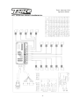
1
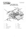
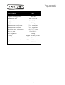
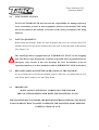
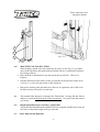
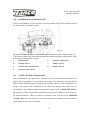
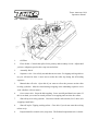
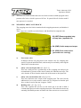
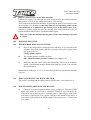
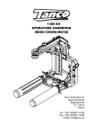
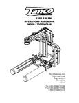
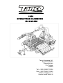
1814 OPERATORS HANDBOOK 1814-M1008 Tanco Autowrap Ltd. Royal Oak Road Bagenalstown Co. Carlow Ireland Tel.: +353 (0)5997 21336 Fax: +353 (0)5997 21560 E-Mail: [email protected] Internet: www.tanco.ie Tanco Autowrap 1814 Operators manual USER'S MANUAL AUTOWRAP 1814 CHAP. CONTENTS PAGE 1.0 INTRODUCTION 4 2.0 SAFETY PRECAUTIONS 6 3.0 SETTING UP / MOUNTING OF THE MACHINE 12 4.0 ELECTRICAL SUPPLY 14 5.0 EMERGENCY STOP* 15 6.0 MOUNTING OF PLASTIC FILM 16 7.0 CONTROLLER 18 8.0 SPEED SETTING OF THE WRAPPING ARM 26 9.0 ADJUSTING THE OVERLAP 26 10.0 OPERATION INSTRUCTION 27 11.0 PERIODIC MAINTENANCE 30 12.0 ELECTRIC CIRCUIT DIAGRAM 33 13.0 DESCRIPTION OF THE HYDRAULICS 34 14.0 CHECK POINTS BEFORE TROUBLE SHOOTING 38 15.0 PROCEEDURE OF TROUBLE SHOOTING 39 16.0 TROUBLE SHOOTING 40 17.0 HYDRAULIC CIRCUIT 42 18.0 DECLARATION OF CONFORMITY 43 2 Tanco Autowrap 1814 Operators manual AUTO WRAP 1814 Bale wrapping machine 1 2 11 12 3 10 9 4 5 8 6 7 1. Tower 7. Stand 2. Wrap arm 8. Linkage bar 3. Bumper 9. Dispenser 4. Cone rollers (optional) 10. E-stop arm 5. Un-loading conveyor 11. Load arm 6. Rocking rollers 12. Cut and start unit 3 Tanco Autowrap 1814 Operators manual 1.0 INTRODUCTION. TANCO AUTOWRAP LTD. congratulates you with the choice of bale wrapping machine. We are certain you will be satisfied with the machine, and that you will have the pleasure of your investment for many years. The 1814 is hydraulically driven using the tractor’s hydraulic oil supply. The 1804 S is equipped with a patented, special mounting for the rollers, which enables the machine to wrap round(*) & square bales. The 1804 S can wrap both square and rectangular bales, from 60 x 60 to 120 x 120 x 190 cm. It can take bales of up to 1500 kg. It can also wrap round bales of up to ø1500 mm. This machine has been in operation since 2007; customer demand has enabled us to develop this well adapted machine for the market. This manual is meant to explain how the 1814 is prepared, mounted, operated and how it works, and along with the spare part's list be a reference for maintenance and troubleshooting. So take good care of this book, it is a part of the machine. Read carefully through this manual, and specially chapter 2.0, safety instructions, before starting the machine, and follow the instructions thoroughly. If problems should occur, ask your dealer for advice before you make the problem worse than it is. See also chapter 13.0, conditions of warranty. TANCO AUTOWRAP LTD. reserves the right to alter the product and/or its technical specifications without prior notice and without this entitling any alterations to previously supplied products. © All rights in pursuance of the Copyright Act shall apply, and any reproduction of the contents of this booklet, in whole or in part, is forbidden without the permission of TANCO AUTOWRAP LTD. Reservation is made for possible printing errors. 4 Tanco Autowrap 1814 Operators manual AUTO WRAP Height in working position 1814 3400 mm Width, min. / max. 2440 / 3215 mm Length, min. / max. 2540 / 3425 mm Weight 4500 kg Wrapping arm speed, recom. 25 rev. per minute Wrapping arm speed, max. 30 rev. per minute Wheel size - max. air pressure 480/45-17 - 2,5bar Bale size, max. Bale weight, max. Capacity Pre-stretcher Oil pressure / amount, min. Electric connection 120x120x190 1500 kg Approx. 50 bales per hour 750 mm 175 bar / 60 litres/minute 12 V DC 5 Tanco Autowrap 1814 Operators manual 2.0 SAFETY PRECAUTIONS. TANCO AUTOWRAP LTD. does not take the responsibility for damages that may occur on machine, persons or other equipment, because of the machine NOT being used as described in this manual, or because of the safety precautions NOT being followed. 2.1 SAFETY EQUIPMENT. Before using the machine, make sure that all guards and covers are securely fitted. The machine must not be operated if a function does not work as described later in this manual. (See chapter 2.4). The AutoWrap 1814 is equipped with an "EMERGENCY STOP" on the wrapping arm. This device stops all functions as quickly as possible, but is by definition not an emergency stop, because it does not interrupt the feed. Nevertheless it has an equivalent function, so we have decided to call it an EMERGENCY STOP in this book. 2.2 BECOME FAMILIAR WITH THE OPERATIONS OF THE MACHINE. If you are unsure how to operate the machine properly, either use of or maintenance to your Auto Wrap, please contact your Auto Wrap dealer. 2.3 IMPORTANT! MAKE ALWAYS SURE THAT NOBODY IS IN THE HAZARD AREA OF THE WRAPPING ARM WHEN THE MACHINE IS IN USE. THE MACHINE MUST NEVER BE OPERATED BY PERSONS WHO DO NOT KNOW ENOUGH ABOUT HOW TO SAFELY OPERATE THE MACHINE, OR BY PERSONS UNDER 16 YEARS OF AGE. 6 Tanco Autowrap 1814 Operators manual 2.4 DANGEROUS AREAS. TANCO AUTOWRAP LTD. has given the safety to the operator the highest priority, but it is still impossible to secure oneself of every danger area on the machine. Therefore we will now go through some of the dangers that can occur when using the Auto Wrap bale wrapper. The 1814 is a large machine with many moving parts. As such there are significant danger area’s associated with it and it is vitally important that the operator is conscious of these and remains vigilant at all times when operating the 1814. 1. IMPACT OF THE WRAPPING ARM. During the wrapping process the arm rotates with a speed of 20-27 revolutions per minute around the bale. On the arm there is mounted a film Dispenser unit with a plastic roll. The Dispensers can give a person serious injuries if one comes to close to the working area of the wrapping arm. To reduce this danger we have mounted an emergency stop* device on the wrapping arm, this stops output for the wrap arm and should stop the wrap arm within two feet of movement when something comes in the way of it. It is very important that this protection always works and that it should not under any circumstances be disconnected. (See more about the emergency stop* in chapter 5.0). Fig 2.2 7 Tanco Autowrap 1814 Operators manual 2. CRUSH HAZARD BETWEEN THE TOWER/CHASSIS AND THE WRAPPING ARM. As earlier explained, we have a wrapping arm with a Dispenser and a plastic roll. The wrapping arm passes the main frame during each rotation. Here there is a risking of crushing if a person stands to close to the main frame when the wrapping arm passes. The distance between the main frame and the wrapping arm is not large enough to give room for a person. The clearance between the Dispenser and the Chassis there is also be a crush hazard. 3. CRUSH HAZARD BETWEEN THE TOWER AND THE WRAPPING ARM. During the main wrapping process the wrapping arm rotates around the bale. Every time the wrapping arm passes the tower/chassis, there is a crush hazard that can be dangerous for the fingers/ arms or bodies. The distance between the stationary and the wrapping arm is between 25-40 mm. 8 Tanco Autowrap 1814 Operators manual Fig 2.3 4. CRUSH HAZARD BETWEEN THE ROLLERS AND THE MAIN FRAME. When adjusting the width of the rollers there is a danger of being trapped and squashed. Keep away from this area, fingers and feet also. (See fig. 2-3). Fig 2.5 5. CRUSH HAZARD CAUSED BY CUT AND START SYSTEM. At the end of the wrapping process the plastic is held tight & cut from the bale. It’s held ready for the start of the next wrapping process. When the cutter arm moves down to hold the plastic, there can occur a trap danger between the cutter arm and the cutter holder. The cutter blade that perforates the plastic is very sharp, so keep hands away from the cutter. (See fig. 2-5). 6. CRUSH HAZARD BETWEEN THE ROLLERS. 9 Tanco Autowrap 1814 Operators manual When the rollers on the machine are moved together, there is not enough space for a person between the rollers. Here there is a danger of being squeezed, so make sure that nobody is between the rollers when they are moved together. (See fig. 2-6). Note that the rocking rollers can rotate and even if they are in the level position they can drop suddenly. There is a serious risk of crushing associated with this. Never stand on the rollers or stand between or lie under them. If you need to work in this area always ensure that everything is in a safe position. i.e rollers are dropped and fully opened and power supply is disconnected 7. CRUSH HAZARD ON THE LOARD ARM. Always ensure that when you are operating the load arm there is nobody in the operating area of it as it could cause serious injury, either by crushing or squeezing. 8. HAZARD ON THE CONVEYOR. Always ensure that when you are operating the unloading conveyor there is nobody in the operating area of it as it could cause serious injury. If the optional rotate conveyor is fitted there is a risk of getting crushed when it is closing. Note: The rollers on the conveyors and the two mounted on the chassis between the rocking rollers and the conveyor are free rolling. Never stand or sit on them as you are likely to loose your balance and cause injury to yourself. 10 Tanco Autowrap 1814 Operators manual 2.5 LOCKING THE CONVEYOR. When the machine is not in use, make sure the unloading conveyor is raised and the locking plate is connected. If the plate is not connected, the conveyor can creep down, causing a hazard on the road or to items the might be beside the machine.(See fig. 2-7). Connecting heavy working implements often has an overall negative effect on the tractor's driving and braking capacity. When transporting on the road always ensure the machines hydraulic brakes are connected to the tractor and that they are functioning correctly. 2.6 TRANSPORTING. When transported on a public road there are certain safety measures that must be taken: 1. Move the wrapping arm into the transport position using the controller. (See Chapter 6) 2. Close the grab fully and raise the load arm fully. 3. Raise the unloading conveyor and secure with the parking braked. (See section 2.5) 4. Ensure machines lights are connected and working correctly. 5. Cut the flow of oil to the machine by disengaging the tractors spool valve and cut the power to the controller by pressing the Red Button on the controller. 11 Tanco Autowrap 1814 Operators manual 3.0 SETTING UP / MOUNTING OF THE MACHINE. Be careful! There is a danger of being crushed when working implements are mounted and connected. Carry out the mounting procedures slowly and carefully, and use separate and approved lifting equipment to make the work easier. See section 2 on safety regulations and pay attention to the various safety decals displayed on different parts of the bale wrapper. 3.1 HINGED TOWER. Because of the freighting of the machine, AUTO WRAP 1814 is sometimes delivered with the tower hinged down. Raise tower by lifting using the lifting eyes. Fit 10 M16 x 50 bolts but do not tighten. Fit the dispenser to the wrap arm. Measure the height from the bottom of the dispenser to the chassis. Rotate the arm around ½ a turn and measure again. Raise or lower the tower until the wrap arm is parallel to the chassis. Tighten up the top links on the back of the tower. Lower the lifting mechanism and check again. If necessary lift again and tighten top links. Then fit the tower support going to the front of the machine. Tighten all bolts and lock top links and after several hours' use, tighten all the bolts once again. 12 Tanco Autowrap 1814 Operators manual Fig 3.4 3.2 Fig 3.5 MOUNTING OF DISPENSERS. The dispensers are mounted using two M12 bolts. The dispenser height should be such that the plastics is being applied as close to the centre of the bale on the end as possible. Generally we recommend that they should be fitted in the lowest position possible (where the plastic just passes over the cut and starts. The height of the bale can then be decided by the width between the rocking rollers. 3.3 MOUNTING OF EMERGENCY STOP* ARM. The machine is equipped with emergency stop-arms on each of the wrap arms. The releasing arm for the emergency stop component must be mounted. Put the arm into the bracket and mount the hinge bolt. Replace the washers and tighten the locking nuts. (See fig. 3-5). The return spring is to be fastened between the eye bolt on the arm and the eye bolt on the bracket. 13 Tanco Autowrap 1814 Operators manual 4.0 Electrical supply The electric supply for the machine's control unit and electro-hydraulic components should come directly from the tractors' 12 volt battery . The electric wires from the battery must have an area measurement of min. 2,5 mm². Connection of other contacts on the tractor can cause risk of malfunction, and is not recommended. Never tamper or remove fuses fitted. Replace fuses with ones of the same rating. BROWN LEADER GOES TO BATTERY PLUS POLE BLUE LEADER GOES TO BATTERY MINUS POLE 14 Tanco Autowrap 1814 Operators manual 5.0 EMERGENCY STOP. Fig 5.2 5.1 The machine is equipped with a safety arm (2) on the wrapping arm (3), and its operation must be tested before work itself is started. 5.2 The safety arm is designed to stop the wrapping arm injuring operators or objects, when starting up or during the wrapping process. 5.3 The emergency stop* is constructed with a "positive" connection, i.e. it has to be in full order before the machine can be started. Note that if there is a fault with the system, the wrap arm will work in manual mode but the controller will not go into automatic. 5.4 This consists of an electrical switch (1) mounted on the arm. This is wired normally open, and the actuating plate attached to the E-Stop arm rests on this and keeps it closed. The signal from the two switches and the film break sensors are fed through the centre of the wrap arm by means of a small electrical coupling. If the electrical circuit is broken, the hydraulic oil flow is cut off and all functions stop immediately. This is indicated on the control box display by ‘EMERGENCY STOP’ 5.5 Before use, this function must be tested. Start the wrapping arm, hold out an arm or any obstacle, the wrapping arm must stop within 700mm. 5.6 To restart the machine the obstacle must be removed and the safety guard must return to its original position. If "STOP" is pressed before "RESTART", the wrapping continues from the point in the program at which the emergency stop was activated. (See more in section 7.) 5.5.1 IMPORTANT: GIVEN THE VELOCITY AND MOMENTUM OF THE ARM IT IS IMPOSSIBLE TO STOP THE WRAP ARM IMMEDIATELY. THE EMERGENCY STOP ARM IS PROVIDED TO HELP REDUCE THE RISK OF SERIOUS INJURY AND GREAT CARE MUST BE TAKEN WHEN OPERATING THIS MACHINE. 15 Tanco Autowrap 1814 Operators manual 2 3 Fig.: 5-4 4 Fig 5.3 6.0 MOUNTING OF PLASTIC FILM. When loading a plastic roll, first ensure the top cone (2) (See Fig 5.3) is pushed up to latched position, then push back the Stretch rollers (3) until held in position by locking catch (4). Place the Roll on the Bottom Cone and release the top latch (1). Beware of Fingers! Pull the film between the rollers on the pre-stretcher in the direction of the arrow. (See fig. 5-4). (See also the sticker on the dispenser) Release the locking catch and allow the rollers to lie against the roll of film. Pull the film from the roll and tie it to the bale. 6.1 The standard film dispenser is designed for 750mm film. If using 500 mm film an adaptor is required which must be ordered separately. See parts book and contact your dealer. 6.2 Height adjustment of pre-stretcher / plastic film. The plastic film should hit at the middle of the bale wrapped, and therefore it may be necessary to adjust the height of the pre-stretcher. 6.3 Tanco Dual Stretch Dispenser 16 Tanco Autowrap 1814 Operators manual Some Tanco Autowrap machines can optionally be fitted with a patented dual stretch gear system. This system enables a quick change of stretch levels on the Film Dispenser. If the bolt (1) is fitted in position 2, the top set of gears provide the stretch (70%). By removing the bolt from position 2 and fitting it in position 3, the bottom set of gears become the stretch gears giving 55% (for use in hotter climates or with square bales). or optionally 33% Tanco Dispenser Gear Combinations Inner Gear Outer Gear % Stretch 60 Tooth 35 Tooth 70% 58 Tooth 37 Tooth 55% 54 Tooth 41Tooth 32% 17 Tanco Autowrap 1814 Operators manual 7.0 1814 Controller Manual Contents 1. INTRODUCTION 1.1.1 IMPORTANT SAFETY INFORMATION! 1.1.2 Main operating Functions and Display 2. OPERATION 2.1 Operation in Automatic mode 2.2 Operation in Manual mode 2.3 Manual options in Automatic mode 2.4 Operations in Manual mode 2.5 The Display Menu 2.6 Selecting a Store Total 2.7 Resetting a Store Total to Zero 2.8 Setting the Number of Wraps 2.9 Film Break Alarm (Optional) 3 OPERATOR SETUP MENU 18 Tanco Autowrap 1814 Operators manual 1. Introduction The Tanco Autowrap Bale Wrap Controller enables the operator to monitor and control the operation of the bale wrapper at any stage of the wrapping cycle. The controller is designed for models : 1814 rotating-arm type wrappers. There are 2 operating modes – Automatic and Manual. The automatic mode permits ‘one-touch wrapping’ to ease the workload on the operator. The controller is fully programmable to optimise wrapping performance. Bale counts are automatically logged in any one of 10 selectable memory stores, in addition to a grand total memory store. 1.1 IMPORTANT SAFETY INFORMATION! • Please read and understand the instructions for using this controller before operating the machine. • This controller is fitted with a pushbutton type On/Off Emergency Stop switch. Always ensure the controller is switched OFF via this switch before attempting any adjustment or maintenance to the machine. • Please follow ALL other safety instructions given in the manufacturers’ Operator Handbook for this machine. 1.2 Main operating Functions and Display The principal instrument features and operating functions are shown in figure 1 below. Figure 1 A 2-line, 32 character dot matrix , back-lit display shows in the normal operating mode: • Current No. of wraps • Target No. of wraps • Wrapping speed (rpm) • Bale total (10 separate 4-way Menu switch to • • • • • Set No. of wraps Change/reset bale sub-total Access Operator Setup menu Access Technician Setup menu Press ESC to switch between normal (N) and secondary function (S) Pause bale rotation (during auto-wrap cycle)- Pause wrapping (Auto) Rotate rollers (Manual) Release film grip Cut and grip film Slow wrap Fast wrap / Resume wrap after manually pausing Reverse wrap arm Add 1 wrap to current (or next) bale Bale load (auto) Bale unload. Discharges the bale from the conveyor (A). Tips & rotates rollers (M) Power On/Off /Emergency Stop 19 Start Automatic cycle (Press STOP switch to stop cycle e.g. in an emergency, to otherwise press pause the cycle) Tanco Autowrap 1814 Operators manual 2 Operation Select Operating Mode 2.1 Operation in Automatic mode The controller is generally used in automatic mode for ‘one touch wrapping’. 1. ‘A’ on the display indicates that the controller is set in Automatic mode. If not, press to select. button* or 2. Place a bale on top of the machine. This is done by pressing the with the controller in N mode it can be done using the Hand controller. 3. Press the switch to commence the automatic wrapping cycle. The cycle is completed when the target number of wraps has been reached. 4. Once wrapping is complete the bale will be discharged onto the unload switch conveyors. You can now load the next bale or if you like press the to unload the bale. Note if your machine has a non-rotate conveyor you must be stationary when doing this. * The controller must be configured in the Operator Setup menu (section 3) so that this is a ‘one touch’ function in automatic mode. Otherwise you must hold the buttons on the hand controller for the required duration (as remains the case in manual mode). 2.2 Manually interrupting an automatic wrapping cycle switch to bring the wrapper to a controlled stop. Pressing the Press the switch will continue the auto-wrap cycle from where it stopped. For safety reasons, if it is necessary to work on the machine (e.g. in the event of a film break or the film running out), then it is strongly recommended that you then switch the controller off via the red stop button and disengage the machine power 2.3 switch after switching the controller back on will resume source. Pressing the the auto-wrap cycle from where it stopped. Unless it is an emergency situation, do not bring the machine to a stop by pressing the red stop button as this will impose unnecessary strain on the machine. Manual options in Automatic mode With the controller in automatic mode, the following manual functions are possible. SLOW WRAP (not during the wrapping sequence). Press to resume the normal fast wrap. REVERSE WRAP ARM (only enabled outside of the wrapping sequence). Press this button to nudge the wrap arm backwards to the desired position. 20 Tanco Autowrap 1814 Operators manual PAUSE BALE ROTATION (function active during auto-wrap cycle). Hold this button to add more film to a particular part of the bale. Release the button when sufficient additional film has been applied. BALE INDEXING (function active in manual mode). Press and hold this button to index the bale. Release the button when the bale is at the desired position. button can also be used to rotate the rollers in manual mode but note that NOTE: The it also unloads the bale! ADD 1 WRAP Each time you press this button an additional wrap will be put on the current bale if the wrapping sequence is in progress, or onto the next bale if the automatic cycle has not yet been started. You can add as many wraps as required. 2.4 Operation in Manual mode ‘M’ on the display indicates that the controller is set in manual mode. If not, press to select. In manual mode you have total control of every stage of the wrapping cycle. The software logic determines which manual functions can be activated at any point in the wrapping cycle. Should the operator incorrectly select a function at a certain stage during the wrapping cycle, then that operation will not be performed. 21 Tanco Autowrap 1814 Operators manual 2.5 The Display Menu The Display menu is divided into 3 sections. At the top level are the settings used during the daily work with the machine – i.e. Store totals and No. of Wraps. The Operator Setup’ section enables the operator to perform adjustments to the machine operation – e.g. time duration and time delay settings during the automatic cycle. The ‘Technician Setup’ menu is not normally accessible to the operator without a PIN access code. ‘Technician Setup’ is not covered by this manual. Use the 4-way switch to navigate the menu. Each menu screen indicates which keys to press to make the settings. The instrument will default back to the main operating display after 30 seconds if no other key is pressed Here is a summary of the display menu; Default 22 Tanco Autowrap 1814 Operators manual 2.6 Selecting a Store Total There are 10 individual memory registers labelled ‘Store A’ to ‘Store J’ for bale totals. Each time a bale cycle is completed, the currently selected store total and the grand total increments by 1. The currently selected store is displayed on one of the two screens selectable in the normal operating mode. The default setting is Store A. To select a particular store, navigate the display menu using the 4-way switch. Press the up/down arrow keys to select the store, then press the ENTER key to confirm the selection. 2.7 Resetting a Store Total to Zero Stores A to J can be individually reset to zero at any time. The Grand Total store cannot be reset. First select the store to be zeroed, then navigate the display menu as shown below. Press the ENTER key to reset. 2.8 Setting the Number of Wraps The default number of wraps is 16. You can set the target number from 0 to 99 by navigating the display menu as shown below. 23 Tanco Autowrap 1814 Operators manual 3 Bale type Setup Menu The 1814 can optionally be fitted with Sensors on the rocking rollers to sense the position of the bale. This is strongly recommended for use with rectangular bales. When it has been set up the machine will use this information from these sensors to sense the position of the bale and it will automatically vary the speed of the rollers during wrapping and thus ensure that we have a consistant overlap (see section 9). It is also useful to allow the bale to be optimally positioned for off-loading. Bale Type Default Settings Factor Rolls slow speed Rolls fast speed Stop Bale Pulse Round 80x90 (square) 120x70 (rectangular) 120x90 (rectangular) 47x80 (rectangular) 47x80 TWIN (square) NA 50% 1 NA 50% 1 39% 55% 1 39% 55% 1 35 50 1 NA 55 3 ROLLS CALIBRATION: To set it up, you must place a bale on the turntable. Go to the Rolls calibration menu and press enter. Then press and hold the top right button (rolls rotate) and allow the bale to do a full rotation. This records the max and min values for each sensor during a rotation. The values are displayed. If they are satisfactory you must press enter to store them. Note: If you do not do a rolls calibration for the particular bale size initially then the proportional control of the rocking rollers during wrapping will not function. Once the values have been saved they remain with that bale size. i.e no need to recalibrate it. IMPORTANT: The default values have been selected as being the optimum for a certain bale size but note that variations can occurs with the particular valves on a machine so it may be necessary to tweak them a bit. Please consult with you dealer if you are unhappy or unsure about the overlap on the bale. 24 Tanco Autowrap 1814 Operators manual 4 Operator Setup Menu The default settings for the machine are developed by Tanco for optimal operation of the machine. However, the operator can change certain parameters in the ‘Operator Setup’ menu to take account of operational conditions. Parameter Default Menu no Description Contrast FULL 4.01 Adjusts the display contrast Film Break OFF 4.02 Set ‘ON’ to enable sensors on the film dispenser. This allows you to continue wrapping with only one dispenser when one runs out. Remote type IR 4.41 Can RF if you using Radio remote. Auto Hand cont. OFF 4.40 If selected you can operate all function from hand controller in automatic. Up Arrow does auto load, Squeeze in is squeeze in, Squeeze out is auto wrap and Down arrow is auto unload. Auto off-load OFF 4.03 If selected that un-loading of the conveyor will take place immediately without being requested by the operator. Squeeze in 0.0s 4.07 Set time period squeezing during auto load sequence Load up 0.0s 4.08 Set time period load arm up during auto load sequence Squeeze out 0.0s 4.09 Set time period grab open during auto load sequence Load down pause 0.0s 4.10 Set time period between grab open and load down during auto load sequence Conveyor down 0.0 4.14 If required you can set the conveyor to be slightly raised while wrapping (by adjusting the conveyor down sensor posn). This sets the time period that it drops for during auto unload sequence Stop bale pulse 1 4.22 Select the no of ½ turns of the wrap arm before the bale starts turning at the start of the wrap sequence. Wraps to release 2 4.23 Selects the no of wraps before it film is released by the Cut and start units Release 2 10 4.24 Selects the no of wraps before the second film release by the Cut and start units Release Delay 0.0 4.25 Selects the delay after the sensor is active on the select rev. Before the cut and starts release. Del to C&S open 0.3 4.44 Selects the delay on the last rev before the cut and starts open fully Delay to slow 0.4 4.26 Selects the delay on the last rev before wrap arms go to slow speed Delay to stop 0.2 4.27 Selects the delay on the last rev before wrap stops (note: it will always reverse back till it sees the sensor) Rotation after 6.0 4.29 The amount of the time the rollers turn for to unload the bale from the Rocking rollers to the unload conveyor Language English 4.35 Select the display language. 25 Tanco Autowrap 1814 Operators manual 9.0 ADJUSTING THE OVERLAP. 9.1 WRAPPING ARM SPEED. Load a bale on to the machine. The wrap arm speed should be set to about 27 rpm. It should be factory set but necessary consult your dealer they can adjust it in the technician menu. Alternatively it may be necessary adjust the flow control which divides the flow on input to the wrapper (see Hydraulic circuit). When the wrapping arm speed is OK, you can set the overlap. 9.2 OVERLAPPING. Commence a wrap cycle and stop it after a few turns of the wrap by pressing the red button. Check that the plastic coming off the dispenser is meeting the plastic already on the bale in a position where more than half the film is overlapping the plastic already on the bale. It is always important to check this with the long side of the bale standing up as this traditionally the side that get least plastic due to the geometric condition with rectangular bales. Approx. 52-53% is the ideal overlap. The overlap is set in the technician level can be varied with bale size. Therefore it is important to select the right bale size and check the overlap whenever you start a new bale size IMPORTANT: If you have less than 50% overlap, what happens is that while most of the bale with have 4 or 6 layers, some narrow strips will have half that. Therefore DAMAGE TO SILAGE! Tanco do not accept liability for any damage to silage as they cannot supervise the wrapping and storage of your bales. It is the responsibility of the operator of the machine to check this. 26 Tanco Autowrap 1814 Operators manual 10.0 OPERATING INSTRUCTIONS. We shall now go through a complete wrapping process, from loading to unloading, and explain the practical use of Tanco 1814. 10.1 Fitting a roll of film. See Section 6.0 10.2 LOADING. For the first bale, ensure that the rollers are set the correct width apart (See Section 10.3) and the dispenser is in the park position close to the film cut & start. Ensuring you have enough room, lower the conveyors (remove parking bracket first) and lower the load arm. Note as the load arm is functions are on the secondary circuit it may be necessary to rev the tractor to have adequate flow to operate it. Note: that the machine overhangs on both sides the tractor when it is folded out. This requires care from the operator not to damage other bales or objects in the field. With the Controller in N mode, Drive into the bale and squeeze it by pressing button on the hand-controller. Then press to raise the load arm close to the rocking rollers. Release the bale by pressing . Then lower the load arm to again by pressing . This sequence can be done automatically by pressing if the controller is configured to operate in this way see section 7.0. However this may not be suitable the oil flow from the tractor varies. 10.3 Setting up the rocking rollers The width between the rocking rollers can be adjusted by changing the position of the width stop pins and moving in and out the Left hand rocking roller frame. For smaller bale move rocking rollers closer together and for larger ones move them apart (See Fig 10.3). There are also rocking roller stops mounted on the rocking roller frames. These limit the drop of the rocking roller frames and do not need to be 27 Tanco Autowrap 1814 Operators manual adjusted in general. Warning There a risk of crushing fingers and limbs when adjusting the rocking rollers! See Section 2.4 The Bale should rotate smoothly; no ‘tumbling’ should be evident. If this occurs adjust one of the roller sets out one hole at a time. The rollers should always run parallel to one another. 10.4 HEIGHT ADJUSTMENT OF FILM DISPENSER. The Dispenser has to be adjusted so that the plastic film is always hitting the centre of the bale. Therefore it is recommended to keep the film dispensers as low as possible and to keep the bale as high as possible (rocking roller width is minimum). 10.5 START. Remember that the plastic film end has to be held in the Cut and start unit or attached to the bale before starting the wrapping cycle. When the tail of the film is held in the cut and start, press the button to start the wrapping cycle in automatic mode. Note as part of the wrap sequence the film will be released automatically after 2 revolutions and again after 5. 10.6 OVERLAP. There should be a film overlap of 50% - 53%. (for adjustment see Section 9.2) This should be checked frequently as changes in hydraulic oil temperature, contaminated oil or valve failure could result in the overlap increasing or decreasing. 10.7 HOW MANY LAYERS OF PLASTIC FILM? Depending on the moisture content and the type of bale being wrapped the typical minimum no of layers required are; * 4 layers – round bales * 6 layers – Square bales. * Follow your plastic manufactures guide on the film layers required 28 Tanco Autowrap 1814 Operators manual Using a 50% overlap (see section 10.6) cover the bale completely in film, then rotate the wrapping arm around the bale 1 more time. This number should be an even number (typically 4 rotations for a round bale). If a small square of plastic was removed from the side of the bale, 2 layers should be found. Note the total number of revolutions on the controller (see section 2.5) and then multiply it by 2 for 4 layers, 3 for 6 layers etc. 10.8 STOP. At the end of the wrapping sequence, before the required number of revolutions is obtained, the speed of the wrapping arm is reduced the cut and start units open to catch and cut the film and the arms go back to the park position, the wrapping arm is then stopped. The bale is now completely wrapped and it is offloaded onto the discharge conveyor. At this stage it is now possible to load the next bale if desired. 10.9 Unloading. When you are in a suitable position to discharge the bale, press the button in automatic mode commences the unload sequence. Note that if you machine not fitted with the optional rotate conveyor you need to be static before doing this. Care must be taken at point of discharge is suitable. A smooth flat area without stones or other sharp objects is necessary. Note also that some grasses have tough stubble which can cause damage to the bales during unloading. Check this with great care. Also ensure that you have adequate room operate. 29 Tanco Autowrap 1814 Operators manual 11.0 PERIODIC MAINTENANCE. 11.1 BEARINGS. All pivot points are fitted with bushes and require regular greasing. Particularly those which are regularly articulating such as all pivot points are the load arm, rocking rollers, discharge conveyor and cut and starts. These should be grease daily. The ball-bearings on the rocking rollers and the dispensers are packed with grease, and do not need any more maintenance. See Figure 11.1. 11.2 FILM DISPENSER. If the machine is in daily use, the Gears under the plastic cover on the dispenser should be greased when needed. 11.3 CUTTER / FILM HOLDER. The cutter / film holder is pre-adjusted from the factory and does not need further adjustments. When replacing spare parts, it is necessary to adjust it. The springs for the U-shaped slot shall be adjusted so that there is 8 - 10mm of bolt exposed below the plate. 11.4 CLEANING. The machine should be cleaned and oiled regularly during and at the end of the wrapping season. NOTE ! When using high pressure washing apparatus, care must be taken with the electrical installation. Also make sure that water is not sprayed directly into the bearings, etc.. Keep the control box protected from rain and water. If necessary use compressed air to dry electrical components. 30 Tanco Autowrap 1814 Operators manual 11.5 HYDRAULIC CYLINDERS. Make sure that all hydraulic cylinders are closed or the exposed cylinder rod is covered in grease when storing the machine. 11.6 QUICK COUPLERS. Ensure that the quick couplers are kept clean and apply the dust caps after use. 11.7 STORAGE. The machine should be parked on a dry place during the closed season. 11.8 OIL FILTER. The oil filter must be changed once a year. 31 Tanco Autowrap 1814 Operators manual 12.0 ELECTRIC CIRCUIT DIAGRAM 1814 32 Tanco Autowrap 1814 Operators manual There are 3 basics, which must ALWAYS be followed if the machine is to function correctly Working Pressure: 175 Bar Hydraulic flow: Back Pressure >55l/min Max 10 Bar / 140Psi Power Supply 12V 33 Tanco Autowrap 1814 Operators manual 13.0 DESCRIPTION OF HYDRAULICS. TANCO AUTOWRAP 1814 is driven by Tractors hydraulic supply. The machine operates an "Open Center". Hydraulic system. Fig 13.1 The operation of the machine is controlled by electro-hydraulic valves as shown in fig. 13.1. The numbers on the cable going onto the hirshmann connectors indicate the function. Refer to the electric and hydraulic circuits. 1 Junction Box 5 Pressure relief valve 2 2 Control valve 1 7 Master Valve 1 3 Control valve 2 (load arm) 8 Master valve 2 4 Pressure relief valve 1 13.1 "OPEN CENTER" HYDRAULICS. Most machines have an “Open Centre” Hydraulic System which delivers a continuous oil supply. The 1814 machine is set as standard to suit this. If no function is activated, the oil flows from the hydraulic pump, through the flow divider where it is split with the priority going to the control valve 1 (Primary circuit) and excess going to the control valve 2 (Secondary circuit). When a function is operated on Control valve 1, MASTER VALVE 1 (4) closes the oil flow circuit to the return on the primary circuit, and allows an oil supply for the required function. When a function is operated on the load arm valve, MASTER VALVE 2 (16) closes the oil flow circuit to the return on the secondary circuit, and allows an oil supply for the required function. 34 Tanco Autowrap 1814 Operators manual 13.2 Hydraulic valves on chassis 1. Oil Filter 2. Flow divider. Controls the split of oil to primary and secondary circuit. Adjust until you have adequate speed on the wrap arm and rollers. 3. Assembly block. 4. Sequence valve. Screw fully out and then in two turns. For tipping rocking roller to tip you will need at least 1 more turn to make the roller tip during the off-loading sequence. 5. Manual shut off valve. Open this if you want to relieve the pressure on the roller leveling cylinders. Must be closed during wrapping or the unloading sequence won’t work (Rollers will not rotate!) 6. Over-center valve. Stops the bale toppling. Screw out fully and then in two turns. If this is too hard you create too much pressure on wrapping and can slow the rollers. 7. Shut off tap to leveling cylinder. Close this with the rollers down (See 5 above) for wrapping round bales. 8. Shut off tap for Tipping rocking rollers. Close this if you do not want the rocking rollers to tip. 9. Proportional flow control valve (wrap arm). The Rollers Proportional valve is below. 35 Tanco Autowrap 1814 Operators manual 13.3 The main valve block and the load arm valve block circuits are both equipped with a pressure relief valve, which is preset to 185 bar. It opens if the oil circuit to tank if max pressure is exceeded. 13.4 WRAPPING ARM VALVE BLOCK. The wrapping arm valve block is attached to the wrapping arm motor, and includes 4 valves. These valves are carefully set in the factory and should not be tampered with. S3 (VMT) Ensures gradual stop of wrap arm. (opposite S4) S4 (VMP) Limits wrap arm torque. S1 (VBS) Over center valve. (prevents over running) a) Non return valve. It shall prevent the oil going back to the control valve for wrapping arm speed. It is placed inside the block, and can only be reached by removing the whole block from the motor. b) Safety valve on the plus side. (S3, fig.13-2). This valve shall provide a gradual stop of the wrapping arm and prevent accumulation of pressure on the motor's outlet side when the arm stops. The valve lets the oil flow from the outlet side of the motor to the input side. c) Safety valve on the minus side. (S4, fig.13-2). This valve limits the max. torque of the wrapping arm. The valve lets the additional oil over to the motors' outlet side. It is adjusted so that the pull force on the far end of the arm is approx. 50 KG. d) Holding valve. (S 1, fig. 13-2) This valve regulates the oil flow on the outlet side to be able to hold a constant input pressure to the wrapping arm motor. This makes the motor run smoothly, and builds pressure on outlet side if the arm tries to overrun itself. 36 Tanco Autowrap 1814 Operators manual IMPORTANT: All these valves have been carefully set in the factory. Incorrect adjustment of these may cause damage to the machine. Always ensure that trained personnel only adjust the settings of these valves. 13.5 THE CUTTER. To prevent the oil pressure to the cutter from falling, so that it holds the film long enough, there is a piloted non-return valve underneath the solenoid valve on the main block. 37 Tanco Autowrap 1814 Operators manual 14.0 CHECK POINTS BEFORE TROUBLE SHOOTING. In this chapter we have some general check points that have to be examined first if something is wrong with the machine. In chapter 17.0 we have a more detailed trouble shooting. There are three basic assumptions that have to be fulfilled if the machine shall function properly: 1. The oil pressure from the tractor should be 180 bar. 2. The return flow of oil has to be as free as possible, max. 10 bar counter pressure. 3. 14.1 Enough electric power to all functions. OIL PRESSURE. In order to check that the oil pressure into the machine is high enough, a gauge may be connected using the test pressure points on the both main valve blocks. When no function is operating the pressure will be the return line pressure. If the pressure is less than 150 bar, there will be less power for the functions. The build up the pressure manually close the master valve or select and hold a function on e.g. CUT& START CLOSE. OIL FLOW. The oil flow that the tractor delivers must be minimum 55 liters/minute, but it is recommended that it is 60 liters/minute. (Max. allowed oil amount is 70 liters/minute). REMEMBER! Large oil amount = Valves get hot. (Small oil tank = insufficient cooling). 14.2 RETURN PRESSURE. The return pressure can be too high. With high return pressure the machine's functions will get less power. High return pressure means also that you need more power to operate the valves. MAX. ALLOWED RETURN PRESSURE IS 10 BAR. We recommend "free return" directly to the tank. 38 Tanco Autowrap 1814 Operators manual 14.3 ELECTRIC POWER. It is important to check that all functions receive enough electric power. If not, some, or all functions may fail. Is the battery voltage high enough? If the voltage falls below 9 volts the valves will not be able to open. Are the cables correctly connected to the battery? Follow directions in chapter 4.4 Is the connection between battery cable and control unit OK? Clean off the poles and check the plug. Is the connection between remote control unit and machine OK? Change contacts if any doubt about the condition. Is the fuse on the battery cable OK? PLEASE CONTACT YOUR DEALER IF YOU ARE IN DOUBT ABOUT ANYTHING. (Remember, always to give your dealer the serial number and production year of your machine when contacting them dealer and ordering spare parts). 15.0 PROCEDURE OF TROUBLE SHOOTING. 15.1 SOLENOID VALVES. When checking if the Solenoid valves are receiving electric power, you do this in the following way with the tractor stopped: 1. 2. 3. Unscrew the nut that holds the solenoid. The solenoid is easy to move without electric power. Push the current function on the remote control. If the solenoid gets power, it will be difficult to move, it "sticks". This is the best and easiest way to check if the solenoid valve is receiving electric power. Another way is to hold a screwdriver up to the magnet. If it "sticks", the solenoid is receiving electric power. The power supply to the valve can also be measured with a voltmeter, but then the contact must be connected to the solenoid, so it is using power. To have reliable functions, the voltage should not be lower than 11,5 volts, even if the solenoid valve usually works with a little lower voltage. 39 Tanco Autowrap 1814 Operators manual 15.2 Only for solenoid valves to the main functions. If the electric supply is in order and one of the functions fails, the reason can be dirt that tightens or prevents the sliding shaft (spool) from moving. Try to maneuver the function manually, by pressing the point of a screwdriver into the end of the valve housing. At the same time the corresponding switch on the control unit has to be operated to get electric power to the master valve. If the function is working again after this, the dirt may have been pushed out in the oil system and the machine can be operated normally again. Take care so that the machines moving parts, do not cause damage to persons or objects. 16.0 TROUBLE SHOOTING. 16.1 THE MACHINE DOES NOT FUNCTION. a) Even if the gauge shows enough pressure and there is no reaction in the machine. The reason could be that one, (or both), of the quick-couplers does not open for the oil. Change quick couplers. b) The counter pressure could be too high. Max. allowed counter pressure is 10 bar. (See chapter 14). c) Make sure that the master valves are functioning. These can be manually closed. Check that the pressure builds when either are closed. You will hear the tractor labour. (Disturbances of this type, a, b or c, are most likely in the first days that the machine is in use). 16.3 THE CUTTER WILL NOT HOLD THE FILM. The pressure is falling and the springs start to lift the cutter. (See chapter 14.2). 16.4 THE WRAPPING ARM WILL NOT ROTATE. a) Check the wrap arm proportional flow valve (see fig 16.4) This gets a PWM signal and cannot be read with a voltmeter. However you can check the connections and if possible put 12 V directly onto it. This will give flow to the wrap arm (i.e full speed) so be careful! Just press the button briefly and if it moves there is the problem the PWM module in the junction box. Consult with your dealer. 40 Tanco Autowrap 1814 Operators manual 16.5 b) Check cross line relief valve (S$). (See fig. 13-2). Screw in one turn and test. If it does not have an effect screw back to original postion. c) The safety valve, (S3, fig. 13-2), can be leaking, so that the oil is passing by the wrapping arm motor. Dismantle and try out if the sliding shaft can move freely. d) The control valve may be blocked. Dismantle and check if the valve works normally. Do not use sharp tools e) Check if the oil motor is working Ask your dealer for advice BEFORE you make the problems bigger and repairing more difficult. f) If the emergency stop* has been activated. To start the machine the control box must be reset (See also chapter 5.0). THE ROLLERS DO NOT ROTATE DURING WRAPPING. a). Check “Stop bale pulse” is set to 1 in operator set-up. See section 7.0 b) Check the Rollers proportional flow valve (see fig 16.5) This gets a PWM signal and cannot be read with a voltmeter. However you can check the connections and if possible put 12 V directly onto it. This will give flow to the rollers (i.e full speed) so be careful! Just press the button briefly and if it moves there is the problem the PWM module in the junction box. Consult with your dealer. 16.6 THE LOAD ARM DOES NOT FUNCTION. I. Is there enough flow going to the machine. Remember the load arm is receiving the excess from the flow divider. Try reving the tractor. Check the flow. Adjust the main flow divider if necessary. II. Check the bypass valve If this is receiving enough power and has free flow, the problem must lie in the solenoid valve. III. Is there enough electric power going to the valves. When the power source is tapped by several users at ones, the voltage can fall so much that all the functions will cut out, or only the width regulating. Check the power source and measure the voltage. 41 Tanco Autowrap 1814 Operators manual 17 Hydraulic Circuit 42 Tanco Autowrap 1814 Operators manual 18.0 Declaration of conformity EC DECLARATION OF CONFORMITY ACCORDING To DIRECTIVES 89/392/336 /EEC AS AMENDED Manufacturer: TANCO ENGINEERING Co LTD BAGENALSTOWN CO CARLOW IRELAND CERTIFIES THAT THE FOLLOWING PRODUCT: TANCO AUTOWRAP 1814 SERIAL NO: To which this declaration relates, corresponds to the essential requirements of the Directive 89/392/336/EEC as amended. To conform to these essential health and safety requirements, the provisions of the following harmonized standards were particularly considered: EN 292-1,2, EN 294, EN 1152, prEN 703, prEN 811, prENl553, prEN 982. DATE: 01.12.2006 SIGNATURE: ____________________________ Con Hourihane TECHNICAL MANAGER 43