1
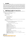
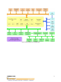
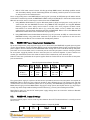
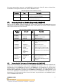
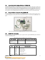
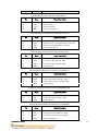
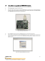
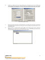
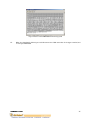
PMS5005 Sensing and Motion Controller User Manual Version: 1.0.5 June 2006 Table of Contents I. II. III. Introduction 2 I.1. PMS5005 Robot Sensing/Motion Controller Architecture 2 I.2. PMS5005 Connectors and Jumpers 4 Operations 4 II.1. PMS5005 Power Supplies and Consumption 5 II.2. PMS5005 Jumper Settings 5 II.3. PMS5005 System Communication Connections 6 II.4. Connecting Peripheral Modules Supported by PMS5005 7 II.5. Connecting DC Motors and Potentiometers to PMS5005 7 II.6. Connecting Custom Sensors/Devices to PMS5005 8 II.7. Sample WiRobot Connection Using PMS5005 8 II.8. PMS5005 Connections 8 Procedure to upgrade the PMS5005 firmware 12 Related Document: WiRobot SDK API Reference Manual Copyright © Dr Robot Inc. 2006 1 I. Introduction The PMS5005 Robot Sensing/Motion Controller can be used as sensing, control, motion execution, LCD display and wireless communication processing unit for various robotic applications. Its onboard firmware makes the low level function modules such as motor driver module and wireless communication module transparent to the users. A host (e.g. PC, DSP, or processor) will be used to communicate and control the PMS5005 for different applications through the UART (serial) interface. The system can help robotic and AI researchers and developers focus on the high level logic and algorithm design, and avoid the hassle of writing low level device drivers, standard control schemes and troubleshooting the electronic circuits. The ease of use, powerful functionality and onboard intelligence can eliminate design risk, streamline hardware and software development, and significantly shorten the time to delivery while effectively reducing the cost. Typical applications include humanoid robot, legged robot, wheel-based robot, robot head, robot arm and robot hand. I.1. PMS5005 Robot Sensing/Motion Controller Architecture As shown in Figure I.1, the PMS5005 features functionalities required by most of the robotic applications, such as sensing, motion control, and data communication. The PMS5005 contains the following features and capabilities: - - 40MIPS 16-bit fix-point hybrid DSP/MCU 36K x 16-bit words flash 2.5K x 16-bit words SRAM Build-in o A/D reference voltage monitoring o Over-heating sensor (x2) o System voltage monitoring (x1) o Watchdog timer (x1) o Full duplex UART (x2) Embedded firmware for configurable closed loop position, velocity, various sensor data acquisition, LCD graphic display, wired and wireless communication Interfaces to o MDM5253 DC motor driver module with position and current feedback (x2), which includes General-purpose PWM DC motor interface (x6) Motor current feedback interface (x6) Potentiometer position feedback sensor interface (x6) o Quadrature encoder (x2) o Standard RC servo motor (x6) o DUR5200 Ultrasonic range sensor module (x6) o DHM5150 Human sensor module (x2) o DAT5280 Ambient temperature sensor module (x1) o GP2Y0A21YK Infrared range sensor (x1) o DTA5102 2 axis tilt/acceleration sensor module (x1) o Custom A/D (x 8 including 3 channels of optional battery voltage monitoring). It can connect to MSA3502 if signal amplifying is needed. o Custom digital input (x8) o Custom digital output (x8) o MGL5128 Graphic LCD display module (128 x 64) (x1) o MIR5538/5540 Full duplex infrared remote control and communication module (x1) o PMB5010 Multimedia controller (x1) o MCB3100 or MCB3101 Serial Bluetooth wireless module, or WFS802b WiFI serial Module, or MCR3210 RS232 interface module (x1) Copyright © Dr Robot Inc. 2006 2 Figure I.1 Block Diagram of the PMS5005 Copyright © Dr Robot Inc. 2006 3 I.2. PMS5005 Connectors and Jumpers Figure I.2 shows the function and location of the connectors and jumpers on the PMS5005. Figure I.2 PMS5005 Connector and Jumper Locations Note that the size of the PCB board of PMS5005 is about 14.5cm x 10.2cm. II. Operations The PMS5005 Robot Sensing/Motion Controller is designed to be running as part of the WiRobot system. The hardware preparation when using the PMS5005 is just simply connecting the relevant WiRobot modules to the relevant connectors on the PMS5005 board and setting the proper jumper configurations. Lower device-level operations are handled by the firmware embedded in PMS5005 controller with the following functions: • Control 6 RC servos • Driver for LCD display, 6 ultrasonic sensors, 2 human sensors, 1 infrared distance sensor, 1 temperature sensor, 1 tilt/acceleration sensor and 1 infrared remote sensor • Can interface with different digital devices through the general digital input and output ports • Can interface with different analog devices through the A/D ports • Built-in voltage monitoring capability Copyright © Dr Robot Inc. 2006 4 • Built-in 3 DC motor control schemes, including open-loop PWM control, closed-loop position control, and closed-loop velocity control. Closed-loop position and velocity control required the use of encoder or rotary sensor as the feedback device Users can physically connect the PMS5005 to a host (e.g. PC, processor, or DSP) through null modem cable or serial wireless modules. By default, the PMS5005’s UART setting is 115200, 8, N, 1 with hardware flow control. With this connection, there are two ways to communicate with the PMS5005: 1. Using WiRobot SDK Software (requires Microsoft platform): High level programs running on PC can communicate with the PMS5005 firmware using WiRobot SDK Component and supplied WiRobot Gateway program. Users simply need to make a function call in their programs to obtain sensor information or to control different devices (e.g. servos, DC motors, and etc.) without the needs to understand the communication details between PC and PMS5005. Please refer to the WiRobot SDK API Reference Manual for further information on programming. 2. Using PMS5005 Communication Protocol: A device (e.g. PC, processor, or DSP) can communicate with PMS5005 directly using packet-level commands. Such option has no requirement on the host and provides the freedom for users to choose their development platform. II.1. PMS5005 Power Supplies and Consumption Up to three independent groups of power supply can be connected to the PMS5005 supporting board system circuits (System Power Supply), DC Motor Power Supply and Servo Motor Power Supply respectively. These power supplies could be connected to the PMS5005 either through the screw terminals or through the power jacks. Near each screw terminal, there is a connector port for connecting the power switch or emergency button for each power supply. By default, all three connector ports are connected together. If power switches are needed, you could disconnect the connection and add a switch in between for each connector port. Table II.1 shows the specification of the power supplies. Refer to Section II.5 for the connections of the power jacks and terminals. Table II.1 Specification of Power Terminals Power Supply Power Jack Screw Terminals Switch Connector System DC Motor Servo Motor J1 J2 J3 PSY PDM PSM S1-0 S1-1 S2-1 Voltage Range (V) 5.5 – 7.2 6.0 – 25.0 5.0 – 7.2 Max Peak Current (A) N/A 12 8 The system power supply is required at all time for the operation of this board and the power consumption of PMS5005 without connecting any peripheral modules is about 350mA using a 7.2V battery pack. We also recommend the use of three different power sources in powering the PMS5005 (System Power Supply, DC Motor Power Supply and Servo Motor Power Supply) since high power consumption devices (e.g. high torque servos) may affect the operation of voltage sensitive devices (e.g. sensors) due to voltage frustration. Note: Please make sure that the DC motor power supply voltage does not exceed the maximum allowable voltage for the DC motors. II.2. PMS5005 Jumper Settings The board address jumpers can be set to any value between 0 and 15. The board address is currently reserved for future use. Table II.2 Board Address Jumpers B_ADDR Bit Copyright © Dr Robot Inc. 2006 Pin Value 1 Value 0 5 0 (LSB) 1 2 3 (MSB) 1, 2 3, 4 5, 6 7, 8 open open open open 1-2 short 3-4 short 5-6 short 7-8 short JP_AD1, JP_AD2 and JP_AD3 are used for enabling and disabling battery voltage monitoring. If the jumper is removed, the corresponding power supply monitoring and custom AD_IN will be disabled.. Table II.3 Battery Voltage Monitoring Jumpers Jumper JP_AD1 1-2 2-3 JP_AD2 1-2 2-3 1-2 2-3 JP_AD3 II.3. Position Battery Voltage Monitoring Enable system power supply monitoring Disable system power monitoring and connect Custom AD_IN1 Enable DC motor power supply monitoring Disable DC motor power and connect Custom AD_IN2 Enable servo motor power supply monitoring Disable servo motor power monitoring and connect Custom AD_IN3 PMS5005 System Communication Connections Under the WiRobot system architecture, all controllers are connected in a chain. There is one and only one host serving as the central controller. All other embedded controllers have at least two SCI ports for the system communications: upper-reach port and lower-reach port, with the direction respect to the central controller. The system communication connection structure of the PMS5005 in the WiRobot system is shown in Figure II.1. PMS5005 can work solely in the WiRobot system or together with WiRobot Multimedia Controller PMB5010 when multimedia data (video and audio) is required in the system. Figure II.1 WiRobot System Communication Architecture Copyright © Dr Robot Inc. 2006 6 The system communication connectors on the PMS5005 are described in Table II.4. Refer to Section II.5 for the definitions of the signals attached to the connector BTOOTH and SCI. Table II.4 System Communication Connectors II.4. Connector Type BTOOTH Upper Reach SCI Lower Reach Description SCI port with handshaking and control signals for both wired and wireless modules Two-wire serial communication interface (reserved for future use) Connecting Peripheral Modules Supported by PMS5005 Table II.5 lists the WiRobot peripheral modules that can be directly connected to the PMS5005 board and supported by the firmware embedded in PMS5005. Refer to the relevant user manuals of these peripheral modules for the detailed technical information. Table II.5 Peripheral Modules Supported by PMS5005 Peripheral Module MCB3100 / MCB3101 MCR3210 WFS802b DUR5200 DTA5102 DHM5150 DAT5280 MIR5538/5540 MDM5253 3rd party 3rd party GP2Y0A21YK MGL5128 II.5. Connector Max No. Description BTOOTH 1 BTOOTH BTOOTH US_1 – 6 TILT 1 1 6 1 HUMAN1 – 2 TEMPERATURE INFRAR MOTOR1_IN, _OUT MOTOR2_IN, _OUT SM1 - 6 ENCODER1 - 2 RANGE LCD 2 1 1 2 Bluetooth wireless communication module RS232 interface module WiFi serial module Ultrasonic range sensor 2-Axis tilting and acceleration sensor Human motion sensor Ambient temperature sensor Infrared remote controller module 3-channel DC motor driver module with position and current feedback 6 2 1 1 3rd party servo motor 3rd party quadrature encoder Infrared range sensor Mono Graphic LCD display module, 128x64 Connecting DC Motors and Potentiometers to PMS5005 In order to connect DC motors and potentiometers to the PMS5005, MDM5253 (DC Motor Driver Module with Position and Current Feedback) is required. Each MDM5253 can control up to 3 DC motors and 3 potentiometers; and each PMS5005 can connect up to 2 MDM5253. The potentiometer can be used as the position feedback of the DC motor for precise position and velocity control. Connector MOTOR1-IN and MOTOR1-OUT on PMS5005 are used to connect to a MDM5253 for DC Motor 1, 2, 3 and Potentiometer 1, 2, 3; and connector MOTOR2-IN and MOTOR2-OUT are used to connect to a MDM5253 for DC Motor 4, 5, 6 and Potentiometer 4, 5, 6. For details on how to connect DC motors and potentiometers to the MDM5253, please refer to the MDM5253 User Manual. Copyright © Dr Robot Inc. 2006 7 II.6. Connecting Custom Sensors/Devices to PMS5005 The PMS5005 has 8 digital inputs, 8 digital outputs and 8 custom A/D extensions. These ports can all be used to connect to different sensors or output devices. For example, user can connect gyroscope, more infrared distance sensors or other analog signal devices to PMS5005 by making use of the available A/D extensions. If a user just wants to have better infrared sensing capabilities in his / her robot, the PMS5005 can support up to 9 infrared distance sensors (GP2Y0A21YK) through its IR range sensor port and the 8 custom A/D expansions. II.7. Sample WiRobot Connection Using PMS5005 The following figure illustrates a simple way in using the PMS5005. Note that only a single 7.2V power source is used to supply power to the system and not all peripheral modules are connected to the PMS5005 in this figure. Figure II.2 Sample Connection of WiRobot PMS5005 with Different Peripheral Modules II.8. PMS5005 Connections The definitions of the connector signals of the power supplies and the supported PMS5005 peripheral modules are listed in the following tables. Table II.6 Connections of the Power Jacks and Terminals Power Connection Power Jack J1, J2, J3 Positive Power Source Power Supply Ground Screw Terminal PSY, PDM, PSM Center Pin 1 Circle 2 Table II.7 Upper Reach Communication Port BTOOTH Pin 1 2 3 4 5 6 7 Copyright © Dr Robot Inc. 2006 Name VCC RXD TXD RTS CTS GND COMRST Signal Description +3.3 V Data receiving Data transmitting Request to send Clear to send Power supply ground Reserved 8 8 BTIN Reserved Table II.8 Lower Reach Communication Port SCI Pin 1 2 3 4 Name VCC RXD TXD GND Signal Description +3.3 V Data receiving Data transmitting Power supply ground Table II.9 Ultrasonic Range Sensor Connectors US_1 - 6 Pin 1 2 3 4 Name VCCA URS UTE GND Signal Description +5.0 V Ultrasonic echo receiving signal, active rising edge Ultrasonic transmitting enable, active high Power supply ground Table II.10 Tilt and Acceleration Sensor Connector TILT Pin 1 2 3 4 Name VCCA AYD AXD GND Signal Description +5.0 V Y direction signal, analog 0 – 3.0V X direction signal, analog 0 – 3.0V Analog ground Table II.11 Human Motion Sensor Connectors HUMAN1 - 2 Pin 1 2 3 4 Name VCCA HMS HAS GND Signal Description +3.0 V Human motion signal, analog 0 – 3.0V Human presence alarm, analog 0 – 3.0V Analog ground Table II.12 Temperature Sensor Connector TEMPERATURE Pin 1 2 3 Name VCCA TVS GND Signal Description +5.0 V Temperature Data, analog 0 – 3.0V Analog ground Table II.13 Infrared Remote Controller Connector INFRAR Pin 1 2 3 4 Copyright © Dr Robot Inc. 2006 Name VCC IRX ITX GND Signal Description +3.3 V Receiving from external device, digital Transmitting to external device, digital Power supply ground 9 Table II.14 Servo Motor Connectors SM1 - 6 Pin 1 2 3 Name SCL VSM GND Signal Description Servo motor control Positive servo motor power supply Servo motor power supply ground Table II.15 Quadrature Encoder Connector ENCODER1 - 2 Pin 1 2 3 4 5 Name ENCB VCC ENCA ENCI GND Signal Description Channel B signal +3.3V Channel A signal Index signal (reserved for future use) Power supply ground Table II.16 Infrared Range Sensor Connector RANGE Pin 1 2 3 Name VCC RVS GND Signal Description +5.0 V Range data, analog 0 – 3.0V Analog ground Table II.17 LCD Display Connector LCD Pin 1 2 3 4 5 6 7 8 9 10 11 12 13 14 15 16 17 18 19 20 Copyright © Dr Robot Inc. 2006 Signal VDD VSS Vo D0 D1 D2 D3 D4 D5 D6 D7 CS1 CS2 RESET R/W D/I E VEE A K Description +5.0V, power supply for logic Power supply ground LCD operating voltage Data bit 0 Data bit 1 Data bit 2 Data bit 3 Data bit 4 Data bit 5 Data bit 6 Data bit 7 Column select 1 ~ 64 Column select 65 ~ 128 Reset input Read/write Data/Instruction indication Enable Negative voltage output Power supply for LED backlight (+) Power supply for LED backlight (-) 10 Table II.18 Custom A/D Expansion Connector EXP-AD Pin Signal 1, 2, 3, 4 5, 6, 15, 16 7 8 9 10 11 12 13 14 + 3.0 V Ground AD_IN1* AD_IN2* AD_IN3* AD_IN4 AD_IN5 AD_IN6 AD_IN7 AD_IN8 Description Analog power supply, max. 40mA Analog ground Analog 0 – 3.0V Analog 0 – 3.0V Analog 0 – 3.0V Analog 0 – 3.0V Analog 0 – 3.0V Analog 0 – 3.0V Analog 0 – 3.0V Analog 0 – 3.0V *Note (Table II.18): When the relevant power supply voltage monitoring is enabled, AD_IN1, AD_IN2, AD_IN3 will be not available to the custom A/D expansions. Table II.19 Custom Digital I/O Expansion Connector EXP-GPIO • Pin Signal Description 1, 2, 3, 4 5 6 7 8 9 10 11 12 13, 14, 15, 16 17* 18* 19* 20* 21* 22* 23* 24* + 3.3 V D_OUT0 D_OUT1 D_OUT2 D_OUT3 D_OUT4 D_OUT5 D_OUT6 D_OUT7 Ground Positive power source, max. 100mA Digital out Digital out Digital out Digital out Digital out Digital out Digital out Digital out Power supply ground D_IN0 D_IN1 D_IN2 D_IN3 D_IN4 D_IN5 D_IN6 D_IN7 Digital in Digital in Digital in Digital in Digital in Digital in Digital in Digital in NOTE (Table II.19): These pins have been pulled-up to logic high (+ 3.3V) internally. Copyright © Dr Robot Inc. 2006 11 III. Procedure to upgrade the PMS5005 firmware 1. Download and save the latest PMS5005 firmware from www.DrRobot.com 2. Turn off PMS5005 and keep it off until step 9 3. Use a null modem cable to connect the PC to PMS5005 with a RS232 Interface Module (MCR3210) as shown in Figure III.1. All peripheral modules (e.g. sensors, motors, LCD and etc.) can still be plugged to the PMS5005 without affecting the upgrade process Figure III.1 Physical Connection 4. Close all WiRobot software on PC (e.g. WiRobot Gateway and all sample applications) 5. Start the hyper-terminal (which comes with MS Windows OS), give a name to this new connection and choose the COM port that is connected to the PMS5005 (normally COM1 or COM2) as shown in the following figure: Figure III.2 Choosing COM Port Connection Copyright © Dr Robot Inc. 2006 12 6. Configure the COM port with the setting 115200, 8, N, 1, Xon/Xoff and turn on the “Echo typed characters locally” under Properties - > Settings -> ASCII Setup. If your PC is slow, you can turn off this “echo” option for shorter download time but you will not see the download process during the upgrade. Figure III.3 COM Port Setting 7. The lower left corner of the hyper-terminal will show the connection status. If the hyper-terminal is still not connected, click the connect icon on the hyper-terminal to establish the connection (don’t turn on the PMS5005 yet!). 8. Choose “Transfer -> Send Text File” from the toolbar and set “files of type” to ALL. Locate the PMS5005 firmware HEX file only by HIGHLIGHTING the file (e.g. PMS5005_v11.dri). Please make sure that you DON’T double click the file or click the “Open” button Copyright © Dr Robot Inc. 2006 13 Figure III.4 Locating the HEX File 9. Please read step 10-13 ahead before turning on the PMS5005 in this step 10. After you turn on the PMS5005 (by connecting power to the system power), you should see the text “(c) 2000-2001 Motorola Inc. S-Record loader. Version 1.1” in the hyper-terminal as shown in the following figure: Figure III.5 Status after Turning on the PMS5005 11. Within 5 seconds (start counting when you turn on the PMS5005), you should click the “Open” button on the Hyper-terminal popup window. Firmware download will then start. If you fail to start the download within this period of time, the original firmware on PMS5005 will automatically start. You have to turn off the PMS5005, and repeat the download procedure again from Step 2 12. When the download is started, hex numbers will appear on the screen if you have turned on the “echo” option as described in step 6. Otherwise, you will not see anything but the download is still running. When the firmware download is completed (takes about 20-60 seconds, depending on the speed of your PC), you will see the “Application Started” keyword as shown in Figure III.6 no matter the “echo” option is turned on or off. The new downloaded firmware will automatically start in few seconds and you should see some un-recognized characters Copyright © Dr Robot Inc. 2006 14 Figure III.6 Successful PMS5005 Firmware Upgrade 13. When the download is finished, you could disconnect the COM connection in the hyper-terminal, and re-start your PMS5005 Copyright © Dr Robot Inc. 2006 15


![[P/N: MCB3101] Class I Serial Bluetooth Wireless](http://vs1.manualzilla.com/store/data/005819698_1-328d04723caa8571829b907b8cc9e0c6-150x150.png)