1
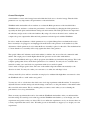
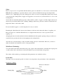
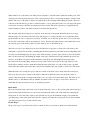
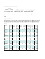
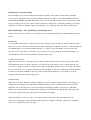
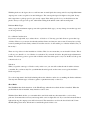
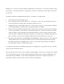
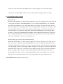
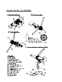
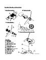
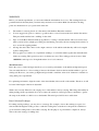
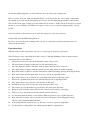
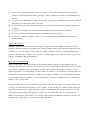
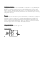
WindPitch
Wind Power Experiment Kit
USER MANUAL
Indhold
General Description ......................................................................................................................... 2
Safety ............................................................................................................................................... 3
Wind Power Technology .................................................................................................................. 3
Assembly.......................................................................................................................................... 9
Experiment Basics.......................................................................................................................... 13
Experiment Ideas............................................................................................................................ 15
General Description
A wind turbine converts wind energy harvested within the blade area to electrical energy. Thus the blade
parameters are very important to the performance of the wind turbine.
WindPitch mini wind turbine allows students to evaluate the Blade parameters of the installed blades.
WindPitch allows students to evaluate the performance of wind turbine by changing the blade parameters,
especially the blade pitch, under different wind speed environments. The blade parameters are important to
the efficiency and protection of the wind turbines. By using a floor fan as the wind source, students can
compare the power output under different blade parameters and wind speeds with the WindPitch.
In order to make the adjustment of blade parameters easy, a Quick Change Rotor mechanism allows the
Rotor Assembly to be plugged to and unplugged from the shaft of the generator of the turbine body. The
adjustment of blade parameter is easier when the Rotor Assembly is placed on the table. The mechanism has
to ensure that the rotor assembly will not slip against the shaft of the generator.
The special 3 Phase AC Alternator used in the turbine is similar to the one used in real commercial wind
turbine. The output power is much higher than the DC generator used in other wind turbines.
3 types of Profiled Blade and 1 types of Poly-propylene sheet Blades are included in the package. This is the
complete package that allows all the blade parameters to be evaluated. You may also use available sheet
materials to make your own blades for experiments with scissors and hole punch.
Vane is made of Polypropylene sheet. The vane on the turbine aligns the turbine automatically to the
direction of wind. You may also make your own vane to see what size and shape is best.
A heavy metal alloy base and base extenders are employed to withstand the high thrust encountered so that
the WindPitch will not “walk” under strong wind.
You may use a floor or desk fan as the wind source for doing experiments with this turbine. You may then
adjust the distance and the wind speed switch settings on the fan to see the performance of the turbine under
this controlled environment. This is something that you cannot control when you are evaluating the
performance of a roof-top wind turbine.
There are many experiments that can be done with the WindPitch wind turbine. After you understand the
basic knowledge about wind power technology and the WindPitch wind turbine, you can design your own
experiments and get the results you desired. We do not outline the experiments one by one because there are
so many experiments that can be done. We rather give more information to support you to design your own
experiments.
Safety
Before you proceed to do experiment with the turbine, please note that the rotor can rotate at a few thousands
RPM (Rotation per Minute), especially when no load is connected. When the wind speed is high and the
turbine is set to output high power, the rotating speed of the rotor can be very high. Body injury may result if
you are hit by the rotating blades. Goggles are suggested to be worn in case your head will be too close to the
rotating blades.
You should also install the turbine properly so that it will not “walk” or topple over. The weight of the base is
increased to prevent the turbine from “walking”. Putting a rubber mat, polyfoam or thin book under the base
helps if the surface of the table is hard.
In case the turbine topples, to avoid being hurt, do not try to catch it.
Extending the “Base Extender” increases the diameter of the base and reduces the chance of toppling over.
Please note that one of the Base Extender has to be aligned in the direction of vane to prevent it from
toppling over.
Arranging the wires from the turbine inside the aluminium tube through the opening on the post and base to
external devices prevents the wires from tangling by the rotating blades.
All of the above measures help to reduce accidents during operation of the turbine. However, you have to
make sure that the environment is safe for doing experiments.
Wind Power Technology
You can learn how the blade pitch affects the power output of the wind turbine to maximize the output power
or stalls (reduces the rotation speed of) the wind turbine to protect itself under strong winds.
The outline of this technology concerning the blade parameters are outlined as follow:
Profile Blade
The shape of the aerodynamic profile of a blade is very important to the performance of the wind turbine.
Designation of Blade:
Direction of Rotation
Rear Side
Trailing Edge
Chord
Front Side (Facing wind)
Leading Edge
When wind blows to the blades, the wind pressure attempts to bend the blades while the smaller parts of the
wind pressure blowing in the direction of the rotation plane produces a torque that attempts to turn the wind
turbine. The force on the blade is almost at a right angle to the resulting wind striking the profile. This force
is known as the lift and also produces a small resistance, or drag. Since the blade is set at an angle (the pitch)
to the plane of rotation, this lift force pushes the blade forward. The blade experiences a significant head
wind resulting from the rotational movement of the blade through the air.
The strength of the lift and drag forces depends on the wind speed and pitch. When the lift force is larger
than the drag force, the blade will rotate faster. The drag force overrides the lift force at a particular blade
pitch when the air can no longer flow smoothly, or lamina, across the blade profile. Air looses contact with
the rear side of the blade, and strong turbulence occurs. We name this phenomena as stall. When this occurs,
the rotation speed of the blades reduces and the output power of the turbine drops.
The basic concept of a profiled blade involves the difference in pressure on both sides of the blade as the
wind path is separated by the blade. Assuming that the wind separated by the blade at the Leading Edge will
be merged at the Trailing Edge, the speed of the wind traveling over the longer side has to travel faster than
that over the shorter side, By making the length of the path on the Rear side longer-than the Front side, the
pressure on the Rear side will be smaller than that on the Front side. The highest wind speed will be
encountered at the Leading Edge, thus the lowest pressure will be developed at this edge. Therefore, the
blade will be sucked forward to make the blade turn faster in the plane of rotation. This is why a profiled
blade makes the turbine turns faster than a sheet blade which has the same length on both sides of the blade.
When the blades are rotating, the speed of the movement of the blade can be many times the wind speed.
Obviously, the speed of movement of the blade is different at different points away from the centre of
rotation. The blade pitch is set larger at the blade root to meet the slower head wind speed. The blade is also
thicker at the root and thinner at the tip. Thicker and wider blade is stronger to resist forces and stresses
while thin and narrow blade has better aerodynamic properties.
Blade Pitch
Please note that the pitch of the blade varies from the blade tip to the root. We use the pitch at the blade tip to
represent the blade pitch because we can read it easier than any other point on the blade. By adjusting the
blade pitch, we can control the output power such that we can get the maximum output power within the
operating range of the wind speed and reduce the output power when the wind speed exceeds the maximum
operating wind speed to protect the turbine itself.
Profile shapes
We provide 3 types of profile blades for the evaluation. They are Custom-28, NACA-44 and NACA-63.
Their Crosss section views are as follow:
Custom-28 Profile, BP-28
28
NACA 44 Profile, BP-44
BP
NACA 63 Profile, BP-63
63
The difference between these 3 profiles is the amount of material on the side facing the wind. All of them
have a much more curved profile
ofile on the Rear side (down wind side) to increase the distance for the wind to
travel.
Output Power Reference
The following table provides a reference for the output power with different types of blades. Please note that
the output power varies with different
ferent load resistance. The maximum output power occurs when the load
resistance is the same as the internal resistance of the generator. This resistance is somewhat between 50 to
75 Ohm.
Turbine
Blade
No. of
Wind
Load
Output
Output
Output
Rotor
Type
Blade
Speed
(Ohm)
Voltage
Current
Power
Speed
(V)
(mA)
(W)
(RPM)
(mph)
WindLab
BS-11
3
12
75
4.0
50
0.2
720
WindLab
BP-38
3
12
75
8.0
100
0.8
1440
WindCharge
BS-11
3
12
75
4.0
50
0.2
720
WindCharge
BP-38
3
12
75
8.0
100
0.8
1440
WindPitch
BS-31
3
12
75
6.0
75
0.45
1035
WindPitch
BP-28
3
12
75
8.0
100
0.8
1440
WindPitch
BP-44
3
12
75
9.0
120
1.08
1730
WindPitch
BP-63
3
12
75
8.5
110
0.935
1550
Plus
Plus
Maximum Power Point Tracking
For real turbine, the converter will track the internal resistance of the turbine, which changes with the
rotation speed, and adjust itself to get the maximum output power. This is done with the Maximum Power
Point Tracking (MPPT) algorithm. This effect can be seen by adjusting a variable wire wound resistor (with
the power rating of the resistor in mind so that it will not be damaged by overheating) with the power being
displayed. You will note that the output power changes as you adjust the resistance of the potentiometer.
Blade Pitch Setting – Start up Wind Speed and Output Power
After selecting the load resistance, you can then do the experiments with the blade pitch and different wind
speeds.
Pitch Setting
To set the pitch of the blade, loosen the top most layer (Safety Locker) and the second layer (Blade Locker).
There is no need to unlock all of them. Twist the Pitch adjusting layer (Pitch Controller) to adjust the pitch. If
the adjusting line does not match with the indicators, you have to move the Pitch Controller layer to the
adjacent slot. You may have to unlock the top two layers more for this. After the desired pitch angle is set,
lock the Blade Locker layer first and then the Safety Locker layer.
Locking and Unlocking
Apply reasonable force to secure the layers so that the adjusted pitch can stay at the desired position. DO
NOT tighten the layers too much, otherwise, you may have problem when you try to unlock them. In case
you screw too tight, you may use a rubber mat to help you unlocking. If this is not good enough, try locking
the second layer in so as to separate the Safety Locker and Blade Locker layer. Afterwards, unlock the Safety
Locker layer and then the Blade Locker layer. This double nut mechanism is to prevent the rotor from
coming apart when it is rotating at high speed.
The Pitch Angle
The blades itself have different set angle at different sections to enhance the performance. This setting is to
compensate the rotating speed of the blade at different radius (section) so that the blade will not stall at a
particular section. You may have to learn a parameter called Tip Speed Ratio to know more. This Ratio
defines how fast the turbine is rotating under a wind speed environment. By changing the blade pitch, this
ratio will be changed. Thus the output power of the turbine is changed.
The pitch indicator on the rotor refers to the pitch at the tip of the blade. The line mark nearest the
semi-circle is the 0 degree mark. Each line mark represents a change of 10 degrees. Therefore, the pitch is
allowed to be adjusted from 0 to 55 degree.
With the pitch set to 0 degree, the rotor will not turn. At small pitch, the start up wind is very high. Maximum
output power occurs at a pitch of around 10 degrees. The start up wind speed is higher at low pitch. It may
take longer time to pick up speed to give steady output. If the wind speed is low, you should increase the
pitch so that you can get some power, rather than nothing if the turbine cannot turn at small pitch.
Different Blade Types
After you get the maximum output power with a particular blade type, you may change for another type and
see how it performs.
No. of Blade Consideration
If you have enough wind, try to reduce the no. of blades to 2. You may get a little bit more power than 3 pc
of blades. However, you may notice that the turbine vibrates and may not start to turn. You may have to help
it start by turning the blade with you hand. You will not need to do this with 3 pcs of blades installed. Do you
know why?
There are 12 positions for the installation of blades. This does not mean that you can install 12 blades. This is
to allow you to install 2, 3, 4 or 6 blades for evaluation. If you install 12 blades, the pitch angle adjustment is
limited. You will not get more power with 12 blades unless the wind speed is very low. In this case the power
content is also low.
Vibration
When you put the same type of blades evenly on the rotor, you can still see that the whole turbine vibrates
somewhat. Do you know why? Do you think that the wind speeds are the same at every point inside the
blade swept area?
To see how important is the blade balancing affects the vibration, and noise, try making the blades unbalance.
You may mix different types of blades together or put them unevenly on the rotor.
Sheet Blade
The WindPitch has all the functions of the WindCharge when the sheet blade holder is installed. When the
profile blade holder is installed, many functions can be done.
With the Sheet Blade holder, you can make their own blades with any sheet materials to see how they
perform. Some materials are heavy and strong while some are light and soft. If you can find a material that is
light and strong, the output power will be increased. The material we used for the sheet blade is 0.75 mm
thick PolyPropylene sheet, which can be found in the plastic folder cover.
Furthermore, you can also modify the length, width and shape of the blades to see how they affect the output
power. The no. of blades installed is also a parameter. You may also modify the size and shape of the vane to
see the effect.
Try all these parameters with different wind speeds, you will have a conclusion that:
1.
Some materials are better than the others
2.
At low wind speed, longer, wider and more no. of blades give out more power. The turbine can start to
rotate easier with these settings, that is, the Start-up wind speed is low..
3.
At high wind speed, shorter, thinner and less no. of blades give out more power. The turbine is difficult
to start rotating with these settings, that is, the Start-up wind speed is higher.
4.
The vane can yaw the turbine against the wind to harvest more power. If you reduce the size and shape
of the vane, the ability to yaw is affected. You may find that the area of the vane is related to the blade
swept area. There is always turbulence that makes the turbine yaw. If you are using a fan as the wind
source and want to disable the yawing due to turbulence, secure this screw to the plastic stud instead of
the grove. That is, secure the screw when the turbine head is in line with the screw on the post.
5.
The setting of the pitch angle of the WindPitch and WindCharge is different. You may observe that their
outputs with the same size of blade are different. You can see how the pitch angle affects the output.
The smaller pitch angle on WindPitch gives out more power but the start up wind speed is higher. It
also takes longer to achieve a stable rotation speed.
To compare the performance with different parameters, try changing only one parameter at a time, otherwise,
you may not know what the effect is.
Since the wind is never steady, in order to take the varying readings, you may choose a strategy. For example,
observe the reading for a period of time and take the highest reading as data, or take the reading that occurs
most frequently. It is difficult to get an accurate reading with a source that is varying. For the purpose of
performance comparison, always stick to the same strategy for taking data.
Assembly
Refer to the attached assembly drawing and the Part List reference numbers for assembly.
I. Main Body Assembly (in case you reassemble it)
Plug the connector of the generator (10) to the socket on the Printed Circuit Board Assembly (11).
Install the Generator (10), Printed Circuit Board Assembly (11) and the Vane (9) in the Main Body
Housing (1 & 2).
Secure the assembly with screws (13) and nuts (16) as shown in the diagram. You may press the 3 nuts
(16) to the Left Housing (1) first with the help of the long screw (14).
II. Blade Unit Assembly
Profiled Blade:
Place the Rotor Base (3) on the table. Install 3 pcs of the same type of profiled blades evenly on the
Rotor Base. Put the Blade Holder (4) on top of the installed blades. Place the Pitch Controller (5) on top
of the Blade Holder. Make sure all the levers of the blades are inserted into the slots on the Pitch
Controller. Check the thin Pitch Indicator lines on the Pitch Controller to see if they points to the Pitch
Markings on the Profile Blade Holder. If it is not the case, move up the Pitch Controller and aligns the
levers of the blades to the adjacent slots. Try rotating the Pitch Controller to see if all the blades are
twisted at the same time. Screw the Blade Locker (8) on top of Pitch Controller. Before you tighten
the Blade Locker, adjust the pitch of the blades to the desired angle. Screw the Safety Locker (9) on top
of the Blade Locker. Do not over tighten it otherwise you may have hard time in unlocking.
Sheet Blade:
Place the Rotor Base (3) on the table. Put the Sheet Blade Lower Holder (6) on the Rotor Base. Install 3
pcs of the Polypropylene Sheet Blade (11) evenly on the Sheet Blade Lower Holder. Place the Sheet
Blade Upper Holder (7) on the Sheet Blade Lower Holder. Screw the Blade Locker (8) on top of the
Sheet Blade Upper Holder. Adjust the Sheet Blades by sliding them to the right side all the way before
you fully lock the Blade Locker layer. This is to ensure that all the Sheet Blades are kept inside the
Blade slots. Screw the Safety Locker (9) on top of the Blade Locker. Do not over tighten it otherwise
you may have hard time in unlocking.
III. Blade Unit Installation
Plug the Blade Unit assembly to the shaft on the Main Body Assembly by aligning the flat side of the
D-Cut shaft against the line mark on the bottom of the Rotor Base. Make sure you press the Blade Unit
all the way to the shaft. Check that the Blade Unit is securely clipped to the shaft of the turbine.
(You may also install the Blade Unit after you assemble the Post and Support Base Assembly.)
IV. Post and Support Base Assembly
Enable Yawing:
Extend the Base Extender (21) fully. Route the output wires from the upper larger hole on the same side
of the screw to the inside of the Aluminium Tube (7) if you want the wind turbine to yaw against the
wind. The wires will have to come out from the other side of the tube. The wires that come out from
this end are further route through the centre hole on the Support Base Assembly for connecting to other
devices. Align the screw hole on the tube to the direction in line with one of the Base Extender if you
want the turbine to yaw against the wind when you install the Aluminium Tube to the Support Base
Assembly (5). Secure the Aluminium Tube with the Post Secure Pin (6). Install the Body Assembly on
the top of the Aluminium Tube and secure it with the screw (15). The screw is secured from the back
side of the wind turbine to the groove of the plastic stud.
Disable Yawing (Not shown in the Assembly Drawing):
Extend the Base Extender (21) fully. Route the output wires from the upper larger hole on the opposite
side of the screw to the inside of the Aluminium Tube (7) if you do not want the wind turbine to yaw
against the wind. The wires will have to come out from the other side of the tube. The wires are further
route through the centre hole on the Support Base Assembly for connecting to other devices. Rotate the
Aluminium Tube another 180˚ as with the position of Enable Yawing when you install the Aluminium
Tube to the Support Base Assembly (5). Secure the Aluminium Tube with the Post Secure Pin (6).
Install the Body Assembly on the top of the Aluminium Tube and secure it with the screw (15). This
time the screw is secured from the front side of the wind turbine to the grid of the plastic stud.
Your WindPitch is now ready to work for you.
Experiment
Experiment Basics
As a user of wind turbine, you always want to get more output power from it. With a particular wind turbine,
meaning that the parameters of it are fixed, can you get more output power when the wind speed is increased?
You can get the answer by doing experiments with a turbine, fan, loading and measuring devices.
Firstly, what are the major parameters of a wind turbine:
1.
Blade Swept Area:- This is the power input area of the wind turbine, refer to the Blade Radius.
2.
Blade Profile:- This provide the Lift and Drag force when the blade turns.
3.
Blade Pitch:- The is the angle at which the Blade intercepts the wind.
4.
No. of Blades:- How many Blades are installed on the Nacelle.
5.
The Generator:- The Nacelle turns the shaft generator. Electricity is generated when the generator
rotates. 3 Phase generator provides more power than a DC generator.
6.
Vane:- This device aligns the wind turbine towards the wind to harvest the maximum wind power.
7.
Stand:- The structure that enable the wind turbine to harvest the wind power.
Secondly, what are the devices that you will connect to the turbine
1.
Resistive type load:- This is the basic element in electrical circuits. There are fix resistors and variable
resistors that you can use to evaluate the power output. Use a resistor of suitable wattage so that it will
not be damaged during operation.
2.
Rechargeable Battery:- For storage of electrical power from the turbine.
Thirdly, what measuring devices do you use for measuring the performance
1.
Anemometer:- For measuring the wind speed
2.
Voltage meter:- For measuring Voltage
3.
Ammeter:- For measuring electrical current
4.
Wattmeter:- For measuring the power generated or consumed
5.
Energy meter:- For measuring the energy generated or consumed during the time interval
In order to learn the wind power technology, you should connect the the wind turbine to a resistive load with
a fan. By measuring the electrical performance under different wind speeds while modifying the parameters
of the wind turbine, you can learn the effects of each parameter while keeping the other constant.
You can multiply the reading of the Voltmeter and Ammeter to get the power output.
From the experiments, you may be inspired to think more on the effects and phenomens of each parameters.
There are so many subjects that can be addressed to with the WindPitch wind turbine. Please see for yourself
as you continue to read this manual.
WARNINGS
Before you start the experiments, you are warned that the wind turbine is not a toy. The rotating blades are
potential hardzous that may hurt you when saftey measures are not taken. Make sure that the following
points are checked before you operate turn on the fan:
1.
The turbine is securely placed on a flat surface with the Base Extender extended.
2.
You are suggested to place a soft mat (e.g. rubber sheet or towel) between the base and the flat surface.
This prevent the turbine from “walking” in the wind.
3.
Tape or tie the Base Extender with strong adhesive or string so that the turbine will not be blown away
when your fan blows at high speed. This prevents hurting yourself by the fast rotating blades when you
try to rescue the toppling turbine.
4.
Arrange the wires that connect to the output connector of the turbine such that they will not be tangled
by the rotating blades.
5.
Wear goggles if you want to do experiments relating to re-orient the turbine against the wind when the
blades are rotating. Take special care not to be hurt in any case. The rotating speed can be more than
3000RPM at wind speed of 12 mph when there is no load connected.
The Wind source:
Fan is the source of wind. A larger fan allows you to test the performance of the turbine at high wind speed.
You can switch the fan to a lower setting or increase the distance between the fan and the turbine to get low
wind speed. However, you cannot get high wind speed with a small fan. A fan of 16” diameter is suitable for
doing wind power experiments.
For optimum performance, align the centre of the fan with that of the nacelle of the turbine. Therefore, it will
be better if the height of the fan is adjustable.
Wind is never steady. Therefore, the output power of the turbine is always varying. This brings uncertainty in
taking readings in the experiments. In order to reduce the variation of wind speed due to turbulence, operate
the setup at the middle of a hall or use a wind tunnel. The wind speed will be more stable then.
Data Collection Technique
For taking varying readings, you may choose a strategy. For example, observe the reading for a period of
time and take the highest reading as data, or take the reading that occurs the most frequent. It is difficult to
get an accurate reading with a source that is varying. For the purpose of performance comparison, always
stick to the same strategy for taking data.
Secure the turbine properly, you will be hurt if your body is hit by the rotating blade.
Before you turn on the fan, make sure that the turbine is secured properly. For some settings of the turbine,
the rotating speed of the nacelle will pick up speed slowly. You may think that the turbine is stable at that
time. As the nacelle gains rotating speed, the turbine may be blown to “walk” away from the fan. If you hold
the base to stop it “walking”, the turbine may topple over. If you try to catch the toppling turbine, you may
be hurt.
Secure the turbine so that it will not move under the wind speed of the fan at any time.
Connect the Load and Measuring Devices
In order to stay away from the rotating blades, it is wise to connect the load and measuring devices at a
distance from the turbine.
Experiment Ideas
When the blades on the wind turbine rotate above a certain speed, electricity is generated.
The following are some experiment ideas that you may do with the WindPitch. There are many advance
experiments that you may think of:
1.
The wind is never steady (See the wind turbine output voltage varies)
2.
The wind direction changes all the time (See the wind turbine yaws)
3.
The vane aligns the turbine towards the wind (Compare when the vane is removed)
4.
The output voltage is highest when the turbine faces the wind (Orient the turbine manually)
5.
How much wind is required to start the wind turbine at different settings (Start up Wind Speed check)
6.
How many blades and what pitch angle are best for start up (Comparing results)
7.
How many blades are more efficient at low and high wind speeds (Comparing results)
8.
What is the optimum blade pitch at low and high wind speeds (Comparing results)
9.
The output voltage is proportional to the wind speed (Plot data)
10. Wind Power is proportional to the cube of the wind speed (Plot data)
11. The rotation speed of the turbine is proportional to the wind speed (Plot data)
12. Rotation speed of turbine reduces when load is connected (See result by connecting)
13. There are noises and vibrations when the turbine operates (Observe)
14. See the effect when the blades are not balance (different positions, types together) (Observe)
15. How generated electricity can be stored and used (in Gold Capacitor and rechargeable battery)
(Observe with a Light and Music Module)
16. Connecting different electrical loads, e.g. DC motor, resistors, capacitors, light bulbs
17. Use the turbine to charge Fuel Cells or Rechargeable Batteries (Applications)
18. You may also integrate the turbine with solar panel to see how they complement each other in real
situations (with Solar Panel and Energy Station) to charge rechargeable batteries (Complement Energy
System)
19. You may test the Wind Farm concept to see how the output power of different wind turbines is affected
when they are connected in parallel or in series
20. You may change the blade and vane parameters to see the output changes under different wind speed
conditions
21. You may custom make your own blade and vane with sheet materials for testing and fun
22. Is the vane effective and what is the shape and minimum size to be effective
23. You may use computer learning systems to record and analyze the performance of the turbine for
further learning
3-Phase AC Alternator
WindLab can generate electricity at low wind speed. It operates on a small 3-Phase AC Alternator (motor
generator). The AC electricity is rectified to DC electricity which can be stored in the Gold Capacitor inside
the turbine or sent to the output connector directly. 3-Phase Alternators are more powerful than DC motor
generators. The life time of 3-Phase motor generators is much longer because they do not have copper brush
contacts (commutator) that wear with time.
Blade and Vane Modification
Blades are important components that need to be matched with the wind speed environment in order to
maximize the efficiency of a turbine. At low wind speed, more blades will be better and the blades should be
long and wide. At high wind speed, the blades should be short and thin. The number of blades is also an
important parameter of a wind turbine. You may install 1 to 6 blades to see the effects, even if the blades are
not balanced symmetrically. However, it is difficult to test these parameters on a real wind turbine. Even if
you can change the blade parameters on a real wind turbine, you cannot command the speed of the natural
wind for you to test the result.
Our wind turbines allow you to evaluate these parameters easily. It comes with a set of 3 sheet blades 3 sets
of 3 types of profiled blade and 1 vane for you to evaluate. You may make your own sheet blades and vanes
with easily available plastic or paper card sheets. Scissors and Punch are the standard stationery needed to
work with your knowledge and imagination to create your own blades and vanes. You can modify the
number, size and shape of the blades to see how the output is affected at different wind speed. You may also
modify the size, shape and color of the vanes to make fun with it.
Quick Plug Rotor Application
The pluggable rotor allows you to install and uninstall the rotor to the turbine body easily. With this Quick
Plug Rotor, you can also pre-assemble several rotor assemblies with different sizes of blades for quick
changes to the turbine. The changes in the output can then be observed immediately under the same wind
condition. The students will understand what parameters of blades are critical in harvesting the wind energy
at that particular wind speed.
Wind Farm
You may connect several wind turbines together to form a Wind Farm. You will learn how to configure the
wind turbines to increase the output voltage or current by connecting them in Series or Parallel. In real
situation, the wind speeds encountered by different turbines in the wind farm are different. The energy
reception of each wind turbine is different and its output voltage and current are different. You will notice
how the final output is affected when the outputs of these turbines are different.
Output Voltage Indication
The higher the voltage, the higher is the output power.
Schematic Diagram: