1
MikroTik RouterOS™ v2.8
Reference Manual
Table Of Contents
Terminal Console.................................................................................. 1
General Information ................................................................................................................ 1
Common Console Functions.................................................................................................... 1
Lists and Item Names............................................................................................................... 3
Quick Typing............................................................................................................................4
Additional Information.............................................................................................................5
General Commands.................................................................................................................. 5
Package Management...........................................................................7
General Information ................................................................................................................ 7
Software Package Installation (Upgrade).................................................................................8
Software Package Uninstalling................................................................................................ 9
Software Package List.............................................................................................................. 9
Specifications Sheet........................................................................... 12
General Information .............................................................................................................. 12
Device Driver List................................................................................ 13
General Information .............................................................................................................. 13
Ethernet.................................................................................................................................. 14
Wireless.................................................................................................................................. 19
Aironet Arlan..........................................................................................................................20
RadioLAN.............................................................................................................................. 21
Synchronous........................................................................................................................... 21
Asynchronous.........................................................................................................................21
ISDN.......................................................................................................................................22
VoIP........................................................................................................................................22
xDSL...................................................................................................................................... 22
HomePNA.............................................................................................................................. 23
LCD........................................................................................................................................ 23
PCMCIA Adapters................................................................................................................. 23
Device Driver Management................................................................ 24
General Information .............................................................................................................. 24
Loading Device Drivers......................................................................................................... 24
Removing Device Drivers...................................................................................................... 26
Notes on PCMCIA Adapters..................................................................................................27
General Interface Settings..................................................................28
General Information .............................................................................................................. 28
Interface Status....................................................................................................................... 29
Traffic Monitoring..................................................................................................................29
FarSync X.21 Interface........................................................................31
General Information............................................................................................................... 31
Synchronous Interface Configuration.................................................................................... 32
Troubleshooting......................................................................................................................33
Synchronous Link Applications............................................................................................. 33
Layer 2 Tunnel Protocol (L2TP)......................................................... 39
General Information............................................................................................................... 39
i
L2TP Client Setup.................................................................................................................. 40
Monitoring L2TP Client.........................................................................................................41
L2TP Server Setup................................................................................................................. 42
L2TP Server Users................................................................................................................. 42
L2TP Application Examples.................................................................................................. 43
Troubleshooting......................................................................................................................48
CISCO/Aironet 2.4GHz 11Mbps Wireless Interface.......................... 50
General Information .............................................................................................................. 50
Wireless Interface Configuration........................................................................................... 51
Troubleshooting......................................................................................................................53
Application Examples............................................................................................................ 54
IP over IP (IPIP) Tunnel Interface....................................................... 58
General Information............................................................................................................... 58
IPIP Setup...............................................................................................................................59
IPIP Configuration................................................................................................................. 59
Ethernet Interfaces..............................................................................61
General Information............................................................................................................... 61
Ethernet Interface Configuration............................................................................................62
Monitoring the Interface Status..............................................................................................63
Moxa C502 Synchronous Interface................................................... 64
General Information............................................................................................................... 64
Synchronous Interface Configuration.................................................................................... 65
Troubleshooting......................................................................................................................66
Synchronous Link Application Examples..............................................................................66
Virtual LAN (VLAN) Interface............................................................. 71
General Information............................................................................................................... 71
VLAN Setup...........................................................................................................................72
Application Example..............................................................................................................73
RadioLAN 5.8GHz Wireless Interface................................................ 75
General Information............................................................................................................... 75
Wireless Interface Configuration........................................................................................... 76
Troubleshooting......................................................................................................................78
Wireless Network Applications..............................................................................................78
Frame Relay (PVC) Interfaces............................................................ 80
General Information............................................................................................................... 80
Configuring Frame Relay Interface........................................................................................81
Frame Relay Configuration.................................................................................................... 81
Troubleshooting......................................................................................................................84
ISDN Interface......................................................................................85
General Information............................................................................................................... 85
ISDN Hardware and Software Installation.............................................................................86
ISDN Client Interface Configuration..................................................................................... 87
ISDN Server Interface Configuration.....................................................................................88
ISDN Examples......................................................................................................................89
Point to Point Tunnel Protocol (PPTP)..............................................93
General Information............................................................................................................... 93
ii
PPTP Client Setup.................................................................................................................. 94
Monitoring PPTP Client.........................................................................................................95
PPTP Server Setup................................................................................................................. 96
PPTP Server Users................................................................................................................. 96
PPTP Application Examples.................................................................................................. 97
Troubleshooting....................................................................................................................102
Wireless Client and Wireless Access Point Manual...................... 104
General Information............................................................................................................. 105
Wireless Interface Configuration......................................................................................... 106
Registration Table................................................................................................................ 109
Access List........................................................................................................................... 110
Info....................................................................................................................................... 111
Virtual Access Point Interface..............................................................................................113
WDS Interface Configuration.............................................................................................. 114
Align.....................................................................................................................................115
Align Monitor.......................................................................................................................116
Network Scan....................................................................................................................... 117
Wireless Security..................................................................................................................117
Wireless Aplication Examples............................................................................................. 119
Ethernet over IP (EoIP) Tunnel Interface........................................ 124
General Information............................................................................................................. 124
EoIP Setup............................................................................................................................125
EoIP Application Example...................................................................................................126
Xpeed SDSL (Single-line Digital Subscriber Line) Interface......... 129
General Information............................................................................................................. 129
Xpeed Interface Configuration.............................................................................................130
Frame Relay Configuration Examples................................................................................. 131
Troubleshooting....................................................................................................................132
Arlan 655 2.4GHz 2Mbps Wireless Interface...................................134
General Information............................................................................................................. 134
Installation............................................................................................................................ 134
Wireless Interface Configuration......................................................................................... 135
Troubleshooting....................................................................................................................136
Bridge Interface................................................................................. 138
General Information............................................................................................................. 138
Bridge Interface Setup..........................................................................................................139
Port Settings......................................................................................................................... 140
Bridge Monitoring................................................................................................................141
Bridge Firewall.....................................................................................................................141
Application Example............................................................................................................143
Troubleshooting....................................................................................................................145
Moxa C101 Synchronous Interface................................................. 146
General Information............................................................................................................. 146
Synchronous Interface Configuration.................................................................................. 147
Troubleshooting....................................................................................................................149
Synchronous Link Application Examples............................................................................149
Cyclades PC300 PCI Adapters......................................................... 154
iii
General Information............................................................................................................. 154
Synchronous Interface Configuration.................................................................................. 155
Troubleshooting....................................................................................................................156
RSV/V.35 Synchronous Link Applications......................................................................... 156
Point to Point Protocol over Ethernet (PPPoE).............................. 159
General Information............................................................................................................. 159
PPPoE Client Setup.............................................................................................................. 160
Monitoring PPPoE Client.....................................................................................................161
PPPoE Server Setup (Access Concentrator)........................................................................ 162
PPPoE Server Users............................................................................................................. 163
Troubleshooting....................................................................................................................164
Application Examples.......................................................................................................... 165
Point to Point Protocol (PPP) and Asynchronous Interfaces....... 168
General Information............................................................................................................. 168
Serial Port Configuration......................................................................................................169
PPP Server Setup..................................................................................................................170
PPP Client Setup.................................................................................................................. 171
PPP Application Example.................................................................................................... 172
IP Addresses and ARP..................................................................... 174
General Information ............................................................................................................ 174
IP Addressing....................................................................................................................... 175
Address Resolution Protocol................................................................................................ 176
Proxy-ARP feature............................................................................................................... 177
Unnumbered Interfaces........................................................................................................ 177
IP Security..........................................................................................179
General Information ............................................................................................................ 179
Policy Settings......................................................................................................................181
Peers..................................................................................................................................... 184
Remote Peer Statistics.......................................................................................................... 185
Installed SAs.........................................................................................................................186
Flushing Installed SA Table................................................................................................. 187
Counters................................................................................................................................187
General Information ............................................................................................................ 188
Routes, Equal Cost Multipath Routing, Policy Routing.................192
General Information ............................................................................................................ 192
Static Routes.........................................................................................................................193
Routing Tables..................................................................................................................... 194
Policy Rules..........................................................................................................................196
Application Examples.......................................................................................................... 197
Connection Tracking and Service Ports......................................... 199
General Information ............................................................................................................ 199
Connection Tracking............................................................................................................ 199
Service Ports.........................................................................................................................200
Packet Marking (Mangle).................................................................. 202
General Information............................................................................................................. 202
Mangle..................................................................................................................................202
iv
Firewall Filters................................................................................... 205
General Information............................................................................................................. 205
Packet Flow.......................................................................................................................... 206
Firewall Rules.......................................................................................................................206
Firewall Chains.....................................................................................................................209
Peer-to-Peer Traffic Control............................................................. 211
General Information ............................................................................................................ 211
Traffic Marking.................................................................................................................... 212
Traffic Filtering.................................................................................................................... 212
Traffic Limiting....................................................................................................................213
Point-to-Point Traffic Control Examples............................................................................. 213
VRRP (Virtual Router Redundancy Protocol)................................. 215
General Information............................................................................................................. 215
VRRP Routers...................................................................................................................... 216
Virtual IP addresses..............................................................................................................217
A simple example of VRRP fail over...................................................................................218
Network Address Translation.......................................................... 220
General Information............................................................................................................. 220
Common NAT Parameters................................................................................................... 221
Source NAT..........................................................................................................................222
Destination NAT.................................................................................................................. 224
Universal Plug and Play (UPnP)...................................................... 225
General Information ............................................................................................................ 225
Enabling Universal Plug-n-Play...........................................................................................226
UPnP Interfaces....................................................................................................................226
DNS Client and Cache...................................................................... 228
General Information ............................................................................................................ 228
DNS Client Configuration....................................................................................................228
Services, Protocols and Ports......................................................... 230
General Information ............................................................................................................ 230
Modifying Service Settings.................................................................................................. 230
List of Services.....................................................................................................................231
HotSpot Gateway.............................................................................. 233
General Information ............................................................................................................ 234
HotSpot Gateway Setup....................................................................................................... 237
HotSpot User Profiles...........................................................................................................239
HotSpot Users.......................................................................................................................241
HotSpot Active Users...........................................................................................................242
HotSpot Remote AAA..........................................................................................................243
HotSpot Server Settings....................................................................................................... 243
HotSpot Cookies.................................................................................................................. 244
Walled Garden......................................................................................................................245
Customizing HotSpot Servlet...............................................................................................246
Possible Error Messages.......................................................................................................248
Question&Answer-Based Setup...........................................................................................249
HotSpot Step-by-Step User Guide for dhcp-pool Method................................................... 250
v
HotSpot Step-by-Step User Guide for enabled-address Method..........................................252
DHCP (Dynamic Host Configuration Protocol)...............................257
General Information ............................................................................................................ 257
DHCP Client Setup.............................................................................................................. 258
DHCP Client Lease.............................................................................................................. 259
DHCP Server Setup..............................................................................................................260
DHCP Networks...................................................................................................................262
DHCP Leases....................................................................................................................... 262
DHCP relay.......................................................................................................................... 264
Question&Answer-Based Setup...........................................................................................265
Universal Client Interface................................................................. 267
General Information ............................................................................................................ 267
Universal Client Interface Setup.......................................................................................... 268
Universal Host List...............................................................................................................269
Universal Access List...........................................................................................................269
Service Port.......................................................................................................................... 270
OSPF.................................................................................................. 271
General Information ............................................................................................................ 271
General Setup....................................................................................................................... 272
Areas.....................................................................................................................................274
Networks.............................................................................................................................. 274
Interfaces.............................................................................................................................. 275
Virtual Links.........................................................................................................................276
Neighbours........................................................................................................................... 277
General Information ............................................................................................................ 278
Certificate Management....................................................................279
General Information ............................................................................................................ 279
Certificates............................................................................................................................280
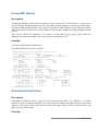
FTP Server......................................................................................... 283
General Information ............................................................................................................ 283
File Transfer Protocol Server............................................................................................... 283
Ping.................................................................................................... 285
General Information............................................................................................................. 285
The Ping Command..............................................................................................................285
MAC Ping Server................................................................................................................. 286
Quality of Service.............................................................................. 288
General Information ............................................................................................................ 288
Queue Types.........................................................................................................................291
Interface Default Queues......................................................................................................292
Configuring Simple Queues................................................................................................. 293
Configuring Queue Trees..................................................................................................... 294
Troubleshooting....................................................................................................................295
Queue Applications.............................................................................................................. 295
Export and Import............................................................................. 300
General Information ............................................................................................................ 300
The Export Command.......................................................................................................... 301
vi
The Import Command.......................................................................................................... 301
Simple Network Management Protocol (SNMP)............................. 303
General Information............................................................................................................. 303
SNMP Setup......................................................................................................................... 304
SNMP Communities............................................................................................................ 304
Available OIDs.....................................................................................................................305
Available MIBs.................................................................................................................... 306
Tools for SNMP Data Collection and Analysis................................................................... 309
MAC Telnet Server and Client.......................................................... 311
General Information ............................................................................................................ 311
MAC Telnet Server.............................................................................................................. 311
Monitoring Active Session List............................................................................................312
MAC Telnet Client...............................................................................................................312
Ping.................................................................................................... 313
General Information............................................................................................................. 313
The Ping Command..............................................................................................................314
MAC Ping Server................................................................................................................. 314
Dynamic DNS (DDNS) Update Tool................................................. 316
General Information ............................................................................................................ 316
Dynamic DNS Update..........................................................................................................317
Realtime Traffic Monitor (torch).......................................................318
General Information............................................................................................................. 318
The Torch Command............................................................................................................318
Bandwidth Test................................................................................. 321
General Information............................................................................................................. 321
Server Configuration............................................................................................................ 322
Client Configuration.............................................................................................................323
Packet Sniffer.................................................................................... 325
General Information............................................................................................................. 325
Packet Sniffer Configuration................................................................................................326
Running Packet Sniffer........................................................................................................ 327
Sniffed Packets..................................................................................................................... 328
Packet Sniffer Protocols....................................................................................................... 329
Packet Sniffer Host...............................................................................................................331
Packet Sniffer Connections.................................................................................................. 331
Traceroute..........................................................................................333
General Information............................................................................................................. 333
The Traceroute Command....................................................................................................334
ICMP Bandwidth Test....................................................................... 335
General Information ............................................................................................................ 335
ICMP Bandwidth Test..........................................................................................................335
System Resource Management....................................................... 337
General Information ............................................................................................................ 337
System Resource.................................................................................................................. 338
IRQ Usage Monitor.............................................................................................................. 338
IO Port Usage Monitor......................................................................................................... 339
vii
Reboot.................................................................................................................................. 339
Shutdown..............................................................................................................................340
Configuration Reset..............................................................................................................340
Router Identity......................................................................................................................341
Date and Time...................................................................................................................... 341
Configuration Change History............................................................................................. 342
Liquid Crystal Display (LCD) Manual.............................................. 344
General Information ............................................................................................................ 344
Configuring the LCD's Settings........................................................................................... 346
LCD Information Display Configuration............................................................................. 346
LCD Troubleshooting...........................................................................................................347
Support Output File.......................................................................... 349
General Information ............................................................................................................ 349
Generating Support Output File........................................................................................... 349
Secure Shell (SSH) Server and Client............................................. 350
General Information ............................................................................................................ 350
SSH Server........................................................................................................................... 351
SSH Client............................................................................................................................351
Backup and Restore......................................................................... 353
General Information ............................................................................................................ 353
General Information ............................................................................................................ 353
Configuration Load Command.............................................................................................354
Serial Console and Terminal............................................................ 355
General Information ............................................................................................................ 355
Serial Console Configuration............................................................................................... 356
Setting Serial Console.......................................................................................................... 356
Using Serial Terminal.......................................................................................................... 357
Global Positioning System (GPS)....................................................358
General Information ............................................................................................................ 358
Synchronizing with a GPS Receiver.................................................................................... 359
GPS Monitoring................................................................................................................... 359
Scripting Host and Complementary Tools......................................361
General Information ............................................................................................................ 362
Console Command Syntax................................................................................................... 362
Expression Grouping............................................................................................................363
Variables...............................................................................................................................364
Command Substitution and Return Values.......................................................................... 365
Operators.............................................................................................................................. 365
Data types............................................................................................................................. 367
Internal Console Expressions (ICE)..................................................................................... 367
Special Actions.....................................................................................................................369
Scripts...................................................................................................................................370
Task Management................................................................................................................ 371
Script Editor......................................................................................................................... 372
Network Watching Tool.......................................................................................................373
UPS Monitor.......................................................................................374
viii
General Information ............................................................................................................ 374
UPS Monitor Setup.............................................................................................................. 375
Runtime Calibration............................................................................................................. 376
UPS Monitoring................................................................................................................... 377
Network Time Protocol (NTP).......................................................... 379
General Information ............................................................................................................ 379
Client.................................................................................................................................... 380
Server....................................................................................................................................381
Time Zone............................................................................................................................ 381
RouterBOARD-specific Functions...................................................383
General Information ............................................................................................................ 383
BIOS upgrading....................................................................................................................384
BIOS Configuration............................................................................................................. 385
System Health Monitoring................................................................................................... 385
Hardware Watchdog Management.......................................................................................386
LED Managment.................................................................................................................. 387
Console Reset Jumper.......................................................................................................... 388
License Management........................................................................ 389
General Information............................................................................................................. 389
License Management............................................................................................................390
Telnet Server and Client................................................................... 393
General Information ............................................................................................................ 393
Telnet Server........................................................................................................................ 393
Telnet Client......................................................................................................................... 394
Log Management...............................................................................395
General Information ............................................................................................................ 395
General Settings................................................................................................................... 396
Log Classification.................................................................................................................396
Log Messages....................................................................................................................... 397
ix
Terminal Console
Document revision 2.0.0 (19-Jan-2004)
This document applies to MikroTik RouterOS V2.8
Table of Contents
Table of Contents
Summary
Specifications
Related Documents
Common Console Functions
Description
Example
Lists and Item Names
Description
Notes
Example
Quick Typing
Description
Notes
Additional Information
Description
General Commands
Description
Command Description
General Information
Summary
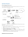
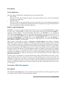
The Terminal Console is used for accessing the MikroTik Router's configuration and management
features using text terminals, id est remote terminal clients or locally attached monitor and
keyboard. The Terminal Console is also used for writing scripts. This manual describes the general
console operation principles. Please consult the Scripting Manual on some advanced console
commands and on how to write scripts.
Specifications
Packages required: system
License required: Any
Hardware usage: Not significant
Related Documents
•
Scripting Host and Complementary Tools
Common Console Functions
Page 1 of 398
Description
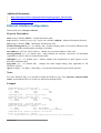
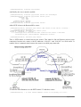
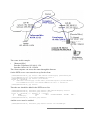
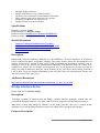
The console allows configuration of the router's settings using text commands. Although the
command structure is similar to the Unix shell, you can get additional information about the
command structure in the Scripting Host and Complementary Tools manual. Since there is a lot
of available commands, they are split into groups organized in a way of hierarchical menu levels.
The name of a menu level reflects the configuration information accessible in the relevant section,
exempli gratia /ip hotspot.
In general, all menu levels hold the same commands. The difference is expressed mainly in
command parameters.
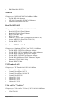
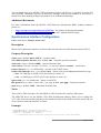
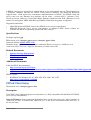
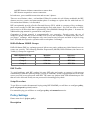
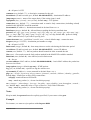
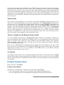
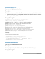
Example
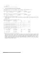
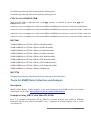
For example, you can issue the /ip route print command:
[admin@MikroTik] > /ip route print
Flags: X - disabled, I - invalid, D - dynamic, J - rejected,
C - connect, S - static, r - rip, o - ospf, b - bgp
#
DST-ADDRESS
G GATEWAY
DISTANCE INTERFACE
0 S 0.0.0.0/0
r 192.168.2.1
1
WAN
1 DC 192.168.124.0/24
r 0.0.0.0
0
LAN
2 DC 192.168.2.0/24
r 0.0.0.0
0
WAN
3 DC 192.168.0.0/24
r 0.0.0.0
0
LAN
[admin@MikroTik] >
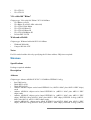
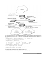
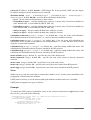
Instead of typing ip route path before each command, the path can be typed only once to move into
this particular branch of menu hierarchy. Thus, the example above could also be executed like this:
[admin@MikroTik] > ip route
[admin@MikroTik] ip route> print
Flags: X - disabled, I - invalid, D - dynamic, J - rejected,
C - connect, S - static, r - rip, o - ospf, b - bgp
#
DST-ADDRESS
G GATEWAY
DISTANCE INTERFACE
0 S 0.0.0.0/0
r 192.168.2.1
1
WAN
1 DC 192.168.124.0/24
r 0.0.0.0
0
LAN
2 DC 192.168.2.0/24
r 0.0.0.0
0
WAN
3 DC 192.168.0.0/24
r 0.0.0.0
0
LAN
[admin@MikroTik] ip route>
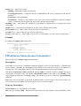
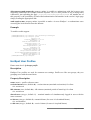
Notice that the prompt changes in order to reflect where you are located in the menu hierarchy at
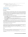
the moment . To move to the top level again, type /:
[admin@MikroTik] > /ip route
[admin@MikroTik] ip route> /
[admin@MikroTik] >
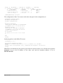
To move up one command level, type ..:
[admin@MikroTik] ip route> ..
[admin@MikroTik] ip>
You can also use / and .. to execute commands from other menu levels without changing the current
level:
[admin@MikroTik] ip route> /ping 10.0.0.1
10.0.0.1 ping timeout
2 packets transmitted, 0 packets received, 100% packet loss
[admin@MikroTik] ip route> .. firewall print
# NAME
Page 2 of 398
POLICY
0
1
2
3
input
forward
output
;;; Limit unauthorized HS clients
hs-temp
4 ;;; account auth HS clients
hotspot
accept
accept
accept
none
none
[admin@MikroTik] ip route>
Lists and Item Names
Description
Lists
Many of the command levels operate with arrays of items: interfaces, routes, users etc. Such arrays
are displayed in similarly looking lists. All items in the list have an item number followed by its
parameter values.
To change parameters of an item, you have to specify it's number to the set command.
Item Names
Some lists have items that have specific names assigned to each. Examples are interface or user
levels. There you can use item names instead of item numbers.
You do not have to use the print command before accessing items by name. As opposed to
numbers, names are not assigned by the console internally, but are one of the items' properties.
Thus, they would not change on their own. However, there are all kinds of obscure situations
possible when several users are changing router's configuration at the same time. Generally, item
names are more "stable" than the numbers, and also more informative, so you should prefer them to
numbers when writing console scripts.
Notes
Item numbers are assigned by print command and are not constant - it is possible that two
successive print commands will order items differently. But the results of last print commands are
memorized and thus, once assigned, item numbers can be used even after add, remove and move
operations (after move operation item numbers are moved with the items). Item numbers are
assigned on per session basis, they will remain the same until you quit the console or until the next
print command is executed. Also, numbers are assigned separately for every item list, so ip
address print would not change numbers for interface list.
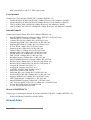
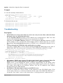
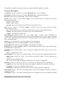
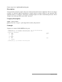
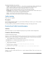
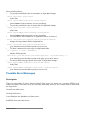
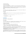
Example
[admin@MikroTik] interface> set 0 mtu=1200
ERROR: item numbers not assigned
[admin@MikroTik] interface> print
Flags: X - disabled, D - dynamic, R - running
#
NAME
0 R WAN
TYPE
ether
MTU
1500
Page 3 of 398
1
R LAN
[admin@MikroTik] interface> set 0
disabled mtu name
[admin@MikroTik] interface> set 0 mtu=1200
[admin@MikroTik] interface> set LAN mtu=1300
[admin@MikroTik] interface> print
Flags: X - disabled, D - dynamic, R - running
#
NAME
0 R WAN
1 R LAN
ether
1500
TYPE
ether
ether
MTU
1200
1300
[admin@MikroTik] interface>
Quick Typing
Description
There are two features in the console that help entering commands much quicker and easier - the
[Tab] key completions, and abbreviations of command names. Completions work similarly to the
bash shell in UNIX. If you press the [Tab] key after a part of a word, console tries to find the
command within the current context that begins with this word. If there is only one match, it is
automatically appended, followed by a space:
/inte[Tab]_
becomes /interface
_
If there is more than one match, but they all have a common beginning, which is longer than that
what you have typed, then the word is completed to this common part, and no space is appended:
/interface set e[Tab]_
becomes /interface
set ether_
If you've typed just the common part, pressing the tab key once has no effect. However, pressing it
for the second time shows all possible completions in compact form:
[admin@MikroTik]
[admin@MikroTik]
[admin@MikroTik]
ether1 ether5
[admin@MikroTik]
> interface set e[Tab]_
> interface set ether[Tab]_
> interface set ether[Tab]_
> interface set ether_
The [Tab] key can be used almost in any context where the console might have a clue about
possible values - command names, argument names, arguments that have only several possible
values (like names of items in some lists or name of protocol in firewall and NAT rules).You
cannot complete numbers, IP addresses and similar values.
Another way to press fewer keys while typing is to abbreviate command and argument names. You
can type only beginning of command name, and, if it is not ambiguous, console will accept it as a
full name. So typing:
[admin@MikroTik] > pi 10.1 c 3 s 100
equals to:
[admin@MikroTik] > ping 10.0.0.1 count 3 size 100
Notes
Pressing [Tab] key while entering IP address will do a DNS lookup, instead of completion. If what
Page 4 of 398
is typed before cursor is a valid IP address, it will be resolved to a DNS name (reverse resolve),
otherwise it will be resolved directly (i.e. to an IP address). To use this feature, DNS server must be
configured and working. To avoid input lockups any such lookup will timeout after half a second,
so you might have to press [Tab] several times, before the name is actually resolved.
It is possible to complete not only beginning, but also any distinctive substring of a name: if there is
no exact match, console starts looking for words that have string being completed as first letters of a
multiple word name, or that simply contain letters of this string in the same order. If single such
word is found, it is completed at cursor position. For example:
[admin@MikroTik] > interface x[TAB]_
[admin@MikroTik] > interface export _
[admin@MikroTik] > interface mt[TAB]_
[admin@MikroTik] > interface monitor-traffic _
Additional Information
Description
Built-in Help
The console has a built-in help, which can be accessed by typing ?. General rule is that help shows
what you can type in position where the ? was pressed (similarly to pressing [Tab] key twice, but in
verbose form and with explanations).
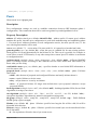
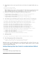
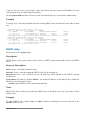
Internal Item Numbers
You can specify multiple items as targets to some commands. Almost everywhere, where you can
write the number of item, you can also write a list of numbers:
[admin@MikroTik] > interface print
Flags: X - disabled, D - dynamic, R - running
#
NAME
TYPE
MTU
0 R ether1
ether
1500
1 R ether2
ether
1500
2 R ether3
ether
1500
3 R ether4
ether
1500
[admin@MikroTik] > interface set 0,1,2 mtu=1460
[admin@MikroTik] > interface print
Flags: X - disabled, D - dynamic, R - running
#
NAME
TYPE
MTU
0 R ether1
ether
1460
1 R ether2
ether
1460
2 R ether3
ether
1460
3 R ether4
ether
1500
[admin@MikroTik] >
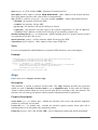
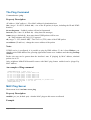
General Commands
Description
There are some commands that are common to nearly all menu levels, namely: print, set, remove,
add, find, get, export, enable, disable, comment, move. These commands have similar behavior
Page 5 of 398
throughout different menu levels.
Command Description
print - shows all information that's accessible from particular command level. Thus, /system clock
print shows system date and time, /ip route print shows all routes etc. If there's a list of items in
current level and they are not read-only, i.e. you can change/remove them (example of read-only
item list is /system history, which shows history of executed actions), then print command also
assigns numbers that are used by all commands that operate with items in this list. - applicable only
to lists of items. The action is performed with all items in this list in the same order in which they
are given. - forces the print command to use tabular output form - specifies what parameters to
include in printout - forces the print command to use property=value output form
set - allows you to change values of general parameters or item parameters. The set command has
arguments with names corresponding to values you can change. Use ? or double [Tab] to see list of
all arguments. If there is a list of items in this command level, then set has one action argument that
accepts the number of item (or list of numbers) you wish to set up. This command does not return
anything.
add - this command usually has all the same arguments as set, except the action number argument.
It adds a new item with values you have specified, usually to the end of list (in places where order is
relevant). There are some values that you have to supply (like the interface for a new route), other
values are set to defaults unless you explicity specify them. - Copies an existing item. It takes
default values of new item's properties from another item. If you do not want to make exact copy,
you can specify new values for some properties. When copying items that have names, you will
usually have to give a new name to a copy - add command returns internal number of item it has
added - places a new item before an existing item with specified position. Thus, you do not need to
use the move command after adding an item to the list - controls disabled/enabled state of the newly
added item(-s) - holds the description of a newly created item
remove - removes item(-s) from a list - contains number(-s) or name(-s) of item(-s) to remove.
move - changes the order of items in list where one is relevant. Item numbers after move command
are left in a consistent, but hardly intuitive order, so it's better to resync them by using print after
each move command. - first argument. Specifies the item(-s) being moved. - second argument.
Specifies the item before which to place all items being moved (they are placed at the end of the list
if the second argument is omitted).
find - The find command has the same arguments as set, and an additional from argument which
works like the from argument with the print command. Plus, find command has flag arguments like
disabled, invalid that take values yes or no depending on the value of respective flag. To see all
flags and their names, look at the top of print command's output. The find command returns internal
numbers of all items that have the same values of arguments as specified.
Page 6 of 398
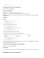
Package Management
Document revision 2.1.0 (15-Jan-2004)
This document applies to MikroTik RouterOS V2.8
Table of Contents
Table of Contents
Summary
Related Documents
Description
Software Package Installation (Upgrade)
Description
Notes
Software Package Uninstalling
Description
Notes
Example
Software Package List
Description
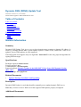
General Information
Summary
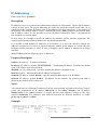
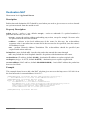
The MikroTik RouterOS is distributed in the form of software packages. The basic functionality of
the router and the operating system itself is provided by the system software package. Other
packages contain additional software features as well as support to various network interface cards.
License required: Any
Home menu level: /system package
Protocols utilized: FTP
Hardware usage: Not significant
Related Documents
•
•
•
Basic Setup Guide
Device Drivers Management
Licenses Management
Description
Features
The modular software package system of MikroTik RouterOS has the following features:
•
•
•
Ability to extend RouterOS functions by installing additional software packages
Optimal usage of the storage space by employing modular/compressed system
Unused software packages can be uninstalled
Page 7 of 398
•
•
•
•
•
•
The RouterOS functions and the system itself can be easily upgraded
Multiple packages can be installed at once
The package dependency is checked before installing a software package. The package will not
be installed, if the required software package is missing
The version of the feature package should be the same as that of the system package
The packages can be uploaded on the router using ftp and installed only when the router is
going for shutdown during the reboot process
If the software package file can be uploaded to the router, then the disk space is sufficient for
the installation of the package
Software Package Installation (Upgrade)
Description
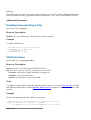
Installation or upgrade of the MikroTik RouterOS software packages can be done by uploading the
newer version of the software package to the router and rebooting it.
The software package files are compressed binary files, which can be downloaded from the
MikroTik's web page download section. The full name of the software package consists of a
descriptive name, version number and extension .npk, exempli gratia system-2.8rc3.npk,
routerboard-2.8rc3.npk.
You should check the available hard disk space prior to downloading the package file by issuing
/system resource print command. If there is not enough free disk space for storing the upgrade
packages, it can be freed up by uninstalling some software packages, which provide functionality
not required for your needs. If you have a sufficient amount of free space for storing the upgrade
packages, connect to the router using ftp. Use user name and password of a user with full access
privileges.
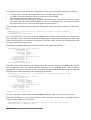
Step-by-Step
•
•
•
•
•
•
Connect to the router using ftp client
Select the BINARY mode file transfer
Upload the software package files to the router and disconnect
Check the information about the uploaded software packages using the /file print command
Reboot the router by issuing the /system reboot command or by pressing Ctrl+Alt+Del keys
at the router's console
After reboot, verify that the packages were installed correctly by issuing /system package
print command
Notes
The packages uploaded to the router should retain the original name and also be in lowercase.
The installation/upgrade process is shown on the console screen (monitor) attached to the router.
The Free Demo License do not allow software upgrades using ftp. You should do a complete
reinstall from floppies, or purchase the license.
Before upgrading the router, please check the current version of the system package and the
additional software packages. The versions of additional packages should match the version number
Page 8 of 398
of the system software package. The version of the MikroTik RouterOS system software (and the
build number) are shown before the console login prompt. Information about the version numbers
and build time of the installed MikroTik RouterOS software packages can be obtained using the
/system package print command.
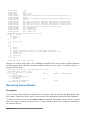
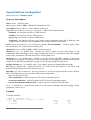
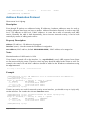
Software Package Uninstalling
Description
Usually, you do not need to uninstall software packages. However, if you have installed a wrong
package, or you need additional free space to install a new one, you have to uninstall some unused
packages.
In order to uninstall software package, you have to set uninstall property for that package to yes
and reboot the router.
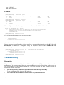
Notes
If a package is marked for uninstallation, but it is required for another (dependent) package, then the
marked package cannot be uninstalled. You should uninstall the dependent package too. For the list
of package dependencies see the 'Software Package LIsk; section below. The system package will
not be uninstalled even if marked for uninstallation.
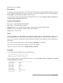
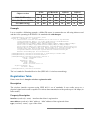
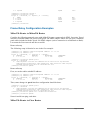
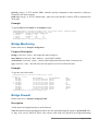
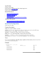
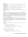
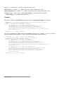
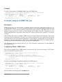
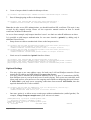
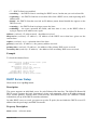
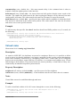
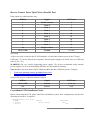
Example
Suppose we need to uninstall security package from the router:
[admin@MikroTik] system package> print
Flags: I - invalid
#
NAME
VERSION
0
system
2.8beta8
1
ppp
2.8beta8
2
advanced-tools
2.8beta8
3
dhcp
2.8beta8
4
routing
2.8beta8
5
security
2.8beta8
6
synchronous
2.8beta8
7
wireless
2.8beta8
BUILD-TIME
oct/21/2003
oct/21/2003
oct/21/2003
oct/21/2003
oct/21/2003
oct/21/2003
oct/21/2003
oct/21/2003
13:27:59
12:31:52
12:31:42
12:31:49
12:31:55
12:31:47
12:32:05
12:32:09
UNINSTALL
no
no
no
no
no
no
no
no
[admin@MikroTik] system package> set 5 uninstall=yes
[admin@MikroTik] > .. reboot
Software Package List
Description
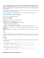
System Software Package
The system software package provides the basic functionality of the MikroTik RouterOS, namely:
•
IP address management, ARP, static IP routing, policy routing, firewall (packet filtering,
content filtering, masquerading, and static NAT), traffic shaping (queues), IP traffic
Page 9 of 398
•
•
•
•
•
•
•
•
•
•
•
•
•
•
•
•
accounting, MikroTik Neighbour Discovery, IP Packet Packing, DNS client settings, IP
service (servers)
Ethernet interface support
IP over IP tunnel interface support
Ethernet over IP tunnel interface support
driver management for Ethernet ISA cards
serial port management
local user management
export and import of router configuration scripts
backup and restore of the router's configuration
undo and redo of configuration changes
network diagnostics tools (ping, traceroute, bandwidth tester, traffic monitor)
bridge support
system resource management
package management
telnet client and server
local and remote logging facility
winbox server as well as winbox executable with some plugins
After installing the MikroTik RouterOS, a free license should be obtained from MikroTik to enable
the basic system functionality.
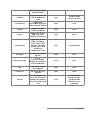
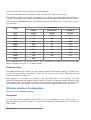
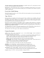
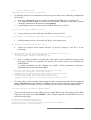
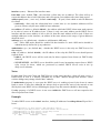
Additional Software Feature Packages
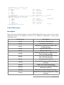
The table below shows additional software feature packages, extended functionality provided by
them, the required prerequisites and additional licenses, if any.
Name
Contents
Prerequisites
Additional License
advanced-tools
email client, pingers,
netwatch and other
utilities
none
none
arlan
support for DSSS
2.4GHz 2mbps
Aironet ISA cards
none
2.4GHz/5GHz
Wireless Client
dhcp
DHCP server and
client support
none
none
gps
support for GPS
devices
none
none
hotspot
HotSpot gateway
none
any additional license
isdn
support for ISDN
devices
ppp
none
lcd
support for
informational LCD
display
none
none
ntp
network time
protocol support
none
none
ppp
support for PPP,
none
none
Page 10 of 398
PPTP, L2TP, PPPoE
and ISDN PPP
radiolan
Provides support for
5.8GHz RadioLAN
cards
none
2.4GHz/5GHz
Wireless Client
routerboard
support for
RouterBoard-specific
functions and utilities
none
none
routing
support for RIP,
OSPF and BGP4
none
none
security
support for IPSEC,
SSH and secure
WinBox connections
none
none
synchronous
support for Frame
Relay and Moxa
C101, Moxa C502,
Farsync, Cyclades
PC300, LMC SBE
and XPeed
synchronous cards
none
Synchronous
telephony
IP telephony support
(H.323)
none
none
thinrouter-pcipc
forces
PCI-to-CardBus
Bridge to use IRQ 11
as in ThinRouters
none
none
ups
APC Smart Mode
UPS support
none
none
web-proxy
HTTP Web proxy
support
none
none
wireless
Provides support for
Cisco Aironet cards,
PrismII and Atheros
wireless stations and
APs
none
2.4GHz/5GHz
Wireless Client /
2.4GHz/5GHz
Wireless Server
(optional)
Page 11 of 398
Specifications Sheet
Document revision 2.4 (18-Feb-2004)
This document applies to MikroTik RouterOS V2.8
Table of Contents
Table of Contents
Description
General Information
Description
Major features
Hardware requirements
Hardware needed for installation time only
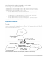
Configuration possibilities
•
•
•
•
•
•
•
Clean and consistent user interface
Runtime configuration and monitoring
Multiple connections
User policies
Action history, undo/redo actions
safe mode operation
Scripts can be scheduled for executing at certain times, periodically, or on events. All
command-line commands are supported in scripts
Page 12 of 398
Device Driver List
Document revision 2.1 (10-Feb-2004)
This document applies to MikroTik RouterOS V2.8
Table of Contents
Table of Contents
Summary
Ethernet
Specifications
Description
Notes
Wireless
Specifications
Description
Aironet Arlan
Specifications
Description
RadioLAN
Specifications
Description
Synchronous
Specifications
Description
Asynchronous
Specifications
Description
ISDN
Specifications
Description
VoIP
Specifications
Description
xDSL
Specifications
Description
HomePNA
Specifications
Description
LCD
Specifications
Description
PCMCIA Adapters
Specifications
Description
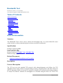
General Information
Page 13 of 398
Summary
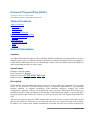
The document lists the drivers, included in MikroTik RouterOS and the devices that are tested to
work with MikroTik RouterOS. If a device is not listed here, it does not mean the device is not
supported, it still may work. It just means that the device was not tested.
Ethernet
Specifications
Packages required: system
Description
3Com 509 Series
Chipset type: 3Com 509 Series ISA 10Base
•
3Com EtherLink III
3Com FastEtherLink
Chipset type: 3Com 3c590/3c900 (3Com FastEtherLink and FastEtherLink XL) PCI 10/100Base
•
•
•
•
•
•
•
•
•
•
•
•
•
•
•
•
•
•
•
•
•
•
•
•
•
3c590 Vortex 10Mbps
3c592 chip
3c595 Vortex 100baseTX
3c595 Vortex 100baseT4
3c595 Vortex 100base-MII
3c597 chip
3Com Vortex
3c900 Boomerang 10baseT
3c900 Boomerang 10Mbps Combo
3c900 Cyclone 10Mbps Combo
3c900B-FL Cyclone 10base-FL
3c905 Boomerang 100baseTX
3c905 Boomerang 100baseT4
3c905B Cyclone 100baseTX
3c905B Cyclone 10/100/BNC
3c905B-FX Cyclone 100baseFX
3c905C Tornado
3c980 Cyclone
3cSOHO100-TX Hurricane
3c555 Laptop Hurricane
3c575 Boomerang CardBus
3CCFE575 Cyclone CardBus
3CCFE656 Cyclone CardBus
3c575 series CardBus
3Com Boomerang
Page 14 of 398
ADMtek Pegasus
Chipset type: ADMtek Pegasus/Pegasus II USB 10/100BaseT
•
•
Planet 10/100Base-TX USB Ethernet Adapter UE-9500
Linksys Instant EtherFast 10/100 USB Network Adapter USB100TX
AMD PCnet
Chipset type: AMD PCnet/PCnet II ISA/PCI 10BaseT
•
•
•
•
AMD PCnet-ISA
AMD PCnet-ISA II
AMD PCnet-PCI II
AMD 79C960 based cards
AMD PCnet32
Chipset type: AMD PCnet32 PCI 10BaseT and 10/100BaseT
•
•
•
AMD PCnet-PCI
AMD PCnet-32
AMD PCnet-Fast
Broadcom Tigon3
Chipset type: Broadcom Tigon3 PCI 10/100/1000BaseT
•
•
•
•
•
•
•
•
•
Broadcom Tigon3 570x
Broadcom Tigon3 5782
Broadcom Tigon3 5788
Broadcom Tigon3 5901
Broadcom Tigon3 5901-2
SysKonnect SK-9Dxx Gigabit Ethernet
SysKonnect SK-9Mxx Gigabit Ethernet
Altima AC100x
Altima AC9100
Davicom DM9102
Chipset type: Davicom DM9102 PCI 10/100Base
•
•
•
•
Davicom DM9102
Davicom DM9102A
Davicom DM9102A+DM9801
Davicom DM9102A+DM9802
DEC 21x4x "Tulip"
Chipset type: DEC 21x4x "Tulip" PCI 10/100Base
•
Digital DC21040 Tulip
Page 15 of 398
•
•
•
•
•
•
•
•
•
•
•
•
•
•
•
•
•
Digital DC21041 Tulip
Digital DS21140 Tulip
21140A chip
21142 chip
Digital DS21143 Tulip
D-Link DFE 570TX 4-port
Lite-On 82c168 PNIC
Macronix 98713 PMAC
Macronix 98715 PMAC
Macronix 98725 PMAC
ASIX AX88140
Lite-On LC82C115 PNIC-II
ADMtek AN981 Comet
Compex RL100-TX
Intel 21145 Tulip
IMC QuikNic FX
Conexant LANfinity
Intel EtherExpressPro
Chipset type: Intel i82557 "Speedo3" (Intel EtherExpressPro) PCI 10/100Base
•
Intel i82557/i82558/i82559ER/i82801BA-7 EtherExpressPro PCI cards
Intel PRO/1000
Chipset type: Intel i8254x (Intel PRO/1000) PCI 10/100/1000Base
•
•
•
•
•
•
•
•
•
•
•
•
•
Intel PRO/1000 Gigabit Server Adapter (i82542, Board IDs: 700262-xxx, 717037-xxx)
Intel PRO/1000 F Server Adapter (i82543, Board IDs: 738640-xxx, A38888-xxx)
Intel PRO/1000 T Server Adapter (i82543, Board IDs: A19845-xxx, A33948-xxx)
Intel PRO/1000 XT Server Adapter (i82544, Board IDs: A51580-xxx)
Intel PRO/1000 XF Server Adapter (i82544, Board IDs: A50484-xxx)
Intel PRO/1000 T Desktop Adapter (i82544, Board IDs: A62947-xxx)
Intel PRO/1000 MT Desktop Adapter (i82540, Board IDs: A78408-xxx, C91016-xxx)
Intel PRO/1000 MT Server Adapter (i82545, Board IDs: A92165-xxx, C31527-xxx)
Intel PRO/1000 MT Dual Port Server Adapter (i82546, Board IDs: A92111-xxx, C29887-xxx)
Intel PRO/1000 MT Quad Port Server Adapter (i82546, Board IDs: C32199-xxx)
Intel PRO/1000 MF Server Adapter (i82545, Board IDs: A91622-xxx, C33915-xxx)
Intel PRO/1000 MF Server Adapter (LX) (i82545, Board IDs: A91624-xxx, C33916-xxx)
Intel PRO/1000 MF Dual Port Server Adapter (i82546, Board IDs: A91620-xxx, C30848-xxx)
Marvell Yukon
Chipset type: Marvell Yukon 88E80xx PCI 10/100/1000Base
•
•
•
•
•
•
3Com 3C940 Gigabit LOM Ethernet Adapter
3Com 3C941 Gigabit LOM Ethernet Adapter
Allied Telesyn AT-2970LX Gigabit Ethernet Adapter
Allied Telesyn AT-2970LX/2SC Gigabit Ethernet Adapter
Allied Telesyn AT-2970SX Gigabit Ethernet Adapter
Allied Telesyn AT-2970SX/2SC Gigabit Ethernet Adapter
Page 16 of 398
•
•
•
•
•
•
•
•
•
•
•
•
•
•
•
•
•
Allied Telesyn AT-2970TX Gigabit Ethernet Adapter
Allied Telesyn AT-2970TX/2TX Gigabit Ethernet Adapter
Allied Telesyn AT-2971SX Gigabit Ethernet Adapter
Allied Telesyn AT-2971T Gigabit Ethernet Adapter
DGE-530T Gigabit Ethernet Adapter
EG1032 v2 Instant Gigabit Network Adapter
EG1064 v2 Instant Gigabit Network Adapter
Marvell 88E8001 Gigabit LOM Ethernet Adapter
Marvell RDK-80xx Adapter
Marvell Yukon Gigabit Ethernet 10/100/1000Base-T Adapter
N-Way PCI-Bus Giga-Card 1000/100/10Mbps(L)
SK-9521 10/100/1000Base-T Adapter
SK-98xx Gigabit Ethernet Server Adapter
SMC EZ Card 1000
Marvell Yukon 88E8010 based
Marvell Yukon 88E8003 based
Marvell Yukon 88E8001 based
National Semiconductor DP83810
Chipset type: National Semiconductor DP83810 PCI 10/100BaseT
•
•
•
RouterBoard 200 built-in Ethernet
RouterBoard 24 4-port Ethernet
NS DP8381x-based cards
National Semiconductor DP83820
Chipset type: National Semiconductor DP83820 PCI 10/100/1000BaseT
•
•
Planet ENW-9601T
NS DP8382x-based cards
NE2000 ISA
Chipset type: NE2000 ISA 10Base
•
various ISA cards
NE2000 PCI
Chipset type: NE2000 PCI 10Base
•
•
•
•
•
•
•
•
•
RealTek RTL-8029
Winbond 89C940 and 89C940F
Compex RL2000
KTI ET32P2
NetVin NV5000SC
Via 86C926
SureCom NE34
Holtek HT80232
Holtek HT80229
Page 17 of 398
•
IMC EtherNic/PCI FO
NS8390
Chipset type: NS8390 PCMCIA/CardBus 10Base
•
•
•
D-Link DE-660 Ethernet
NE-2000 Compatible PCMCIA Ethernet
NS8390-based PCMCIA cards
RealTek RTL8129
Chipset type: RealTek RTL8129 PCI 10/100Base
•
•
•
•
•
•
•
RealTek RTL8129 Fast Ethernet
RealTek RTL8139 Fast Ethernet
RTL8139A/B/C chip
RTL8130 chip
SMC1211TX EZCard 10/100 (RealTek RTL8139)
Accton MPX5030 (RealTek RTL8139)
D-Link DFE 538TX
Sundance ST201 "Alta"
Chipset type: Sundance ST201 "Alta" PCI 10/100Base
•
•
•
•
•
•
•
D-Link DFE-550TX Fast Ethernet Adapter
D-Link DFE-550FX 100Mbps Fiber-optics Adapter
D-Link DFE-580TX 4-port Server Adapter
D-Link DFE-530TXS Fast Ethernet Adapter
D-Link DL10050-based FAST Ethernet Adapter
Sundance ST201 "Alta" chip
Kendin KS8723 chip
TI ThunderLAN
Chipset type: TI ThunderLAN PCI 10/100Base
•
•
•
•
•
•
•
•
Compaq Netelligent 10 T
Compaq Netelligent 10 T/2
Compaq Netelligent 10/100 TX
Compaq NetFlex-3/P
Olicom OC-2183
Olicom OC-2185
Olicom OC-2325
Olicom OC-2326
VIA vt612x "Velocity"
Chipset type: VIA vt612x "Velocity" PCI 10/100/1000Base
•
VIA VT6120
Page 18 of 398
•
•
VIA VT6121
VIA VT6122
VIA vt86c100 "Rhine"
Chipset type: VIA vt86c100 "Rhine" PCI 10/100Base
•
•
•
•
•
•
•
VIA Rhine (vt3043)
VIA Rhine II (vt3065 AKA vt86c100)
VIA VT86C100A Rhine
VIA VT6102 Rhine-II
VIA VT6105 Rhine-III
VIA VT6105M Rhine-III
D-Link DFE 530TX
Winbond w89c840
Chipset type: Winbond w89c840 PCI 10/100Base
•
•
Winbond W89c840
Compex RL100-ATX
Notes
For ISA cards load the driver by specifying the I/O base address. IRQ is not required.
Wireless
Specifications
Packages required: wireless
Description
Atheros
Chipset type: Atheros AR5001X PC/PCI 11/54Mbit/s IEEE802.11a/b/g
•
•
•
•
•
•
•
Intel 5000 series
Dlink DWL-A520
Dlink DWL-G650
Atheros AR5000 chipset series based IEEE802.11a (AR5210 MAC plus AR5110 PHY chips)
cards
Atheros AR5001A chipset series based IEEE802.11a (AR5211 MAC plus AR5111 PHY
chips) cards
Atheros AR5001X chipset series based IEEE802.11a (AR5211 MAC plus AR5111 PHY
chips), IEEE802.11b/g (AR5211 MAC plus AR2111 PHY chips), IEEE802.11a/b/g (AR5211
MAC plus AR5111 and 2111 PHY chips) cards
Atheros AR5001X+ chipset series based IEEE802.11a (AR5212 MAC plus AR5111 PHY
chips), IEEE802.11b/g (AR5212 MAC plus AR2111 PHY chips), IEEE802.11a/b/g (AR5212
Page 19 of 398
MAC plus AR5111 and 2111 PHY chips) cards
Cisco/Aironet
Chipset type: Cisco/Aironet ISA/PCI/PC 11Mbit/s IEEE802.11b
•
•
•
•
Aironet ISA/PCI/PC4800 2.4GHz DS 11Mbps Wireless LAN Adapters (100mW)
Aironet ISA/PCI/PC4500 2.4GHz DS 2Mbps Wireless LAN Adapters (100mW)
CISCO AIR-PCI340 2.4GHz DS 11Mbps Wireless LAN Adapters (30mW)
CISCO AIR-PCI/PC350/352 2.4GHz DS 11Mbps Wireless LAN Adapters (100mW)
Intersil Prism II
Chipset type: Intersil Prism II PC/PCI 11Mbit/s IEEE802.11b
•
•
•
•
•
•
•
•
•
•
•
•
•
•
•
•
•
•
•
•
•
•
•
•
•
•
•
Intersil PRISM2 Reference Design 11Mb/s IEEE802.11b WLAN Card
GemTek WL-211 Wireless LAN PC Card
Compaq WL100/200 11Mb/s 802.11b WLAN Card
Compaq iPaq HNW-100 11Mb/s 802.11b WLAN Card
Samsung SWL2000-N 11Mb/s 802.11b WLAN Card
Z-Com XI300 11Mb/s 802.11b WLAN Card
ZoomAir 4100 11Mb/s 802.11b WLAN Card
Linksys WPC11 11Mbps 802.11b WLAN Card
Addtron AWP-100 11Mbps 802.11b WLAN Card
D-Link DWL-650 11Mbps 802.11b WLAN Card
SMC 2632W 11Mbps 802.11b WLAN Card
BroMax Freeport 11Mbps 802.11b WLAN Card
Intersil PRISM2 Reference Design 11Mb/s WLAN Card
Bromax OEM 11Mbps 802.11b WLAN Card (Prism 2.5)
Bromax OEM 11Mbps 802.11b WLAN Card (Prism 3)
corega K.K. Wireless LAN PCC-11
corega K.K. Wireless LAN PCCA-11
CONTEC FLEXSCAN/FX-DDS110-PCC
PLANEX GeoWave/GW-NS110
Ambicom WL1100 11Mbps 802.11b WLAN Card
LeArtery SYNCBYAIR 11Mbps 802.11b WLAN Card
Intermec MobileLAN 11Mbps 802.11b WLAN Card
NETGEAR MA401 11Mbps 802.11 WLAN Card
Intersil PRISM Freedom 11mbps 802.11 WLAN Card
OTC Wireless AirEZY 2411-PCC 11Mbps 802.11 WLAN Card
Z-Com XI-325HP PCMCIA 200mW Card
Z-Com XI-626 Wireless PCI Card
WaveLAN/ORiNOCO
Chipset type: Lucent/Agere/Proxim WaveLAN/ORiNOCO ISA/PC 11Mbit/s IEEE802.11b
•
WaveLAN Bronze/Gold/Silver ISA/PCMCIA
Aironet Arlan
Page 20 of 398
Specifications
Packages required: arlan
Description
This is driver for legacy Aironet Arlan cards, not for newer Cisco/Aironet cards.
Chipset type: Aironet Arlan IC2200 ISA 2Mbit/s IEEE802.11b
•
Aironet Arlan 655
RadioLAN
Specifications
Packages required: radiolan
Description
This is driver for legacy RadioLAN cards.
Chipset type: RadioLAN ISA/PC 10Mbit/s 5.8GHz
•
•
RadioLAN ISA card (Model 101)
RadioLAN PCMCIA card
Synchronous
Specifications
Packages required: synchronous
Description
•
•
•
•
•
Moxa C101 V.35 (4 Mbit/s)
Moxa C502 PCI 2-port V.35 (8 Mbit/s)
Cyclades PC-300 V.35 (5 Mbit/s)
Cyclades PC-300 E1/T1
FarSync V.35/X.21 (8.448 Mbit/s)
Asynchronous
Specifications
Packages required: system
Description
•
Standard Communication Ports Com1 and Com2
Page 21 of 398
•
•
•
Moxa Smartio C104H, C168H, CP-114, CP-132, CP-168U, CP-104U, CP-134U, CP-132U
PCI 2/4/8 port up to 4 cards (up to 32 ports)
Cyclades Cyclom-Y and Cyclades-Z Series up to 32 ports per card, up to 4 cards (up to 128
ports)
TCL DataBooster 4 or 8 PCI cards
ISDN
Specifications
Packages required: isdn
Description
•
•
•
•
•
•
•
•
•
•
Eicon.Diehl Diva PCI
Sedlbauer Speed Card PCI
ELSA Quickstep 1000PCI
Traverse Technologie NETjet PCI S0 card
Teles PCI
Dr. Neuhaus Niccy PCI
AVM Fritz PCI
Gazel PCI ISDN cards
HFC-2BS0 based PCI cards (TeleInt SA1)
Winbond W6692 based PCI cards
VoIP
Specifications
Packages required: telepony
Description
•
•
•
•
QuickNet LineJack ISA
QuickNet PhoneJack ISA
Voicetronix V4PCI - 4 analog telephone lines cards
Zaptel X.100P IP telephony card (1 analog line)
xDSL
Specifications
Packages required: synchronous
Description
Xpeed 300 SDSL cards (up to 6.7km twisted pair wire connection, max 2.3Mbit/s)
Page 22 of 398
HomePNA
Specifications
Packages required: system
Description
Linksys HomeLink PhoneLine Network Card (up to 10Mbit/s home network over telephone line)
LCD
Specifications
Packages required: lcd
Description
•
•
Crystalfontz Intelligent Serial LCD Module 632 (16x2 characters) and 634 (20x4 characters)
Powertip Character LCD Module PC2404 (24x4 characters)
PCMCIA Adapters
Specifications
Packages required: system
Description
•
•
•
Vadem VG-469 PCMCIA-ISA adapter (one or two PCMCIA ports)
RICOH PCMCIA-PCI Bridge with R5C475 II or RC476 II chip (one or two PCMCIA ports)
CISCO/Aironet PCMCIA adapter (ISA and PCI versions) for CISCO/Aironet PCMCIA cards
only
Page 23 of 398
Device Driver Management
Document revision 2.1.0 (15-Jan-2003)
This document applies to MikroTik RouterOS V2.8
Table of Contents
Table of Contents
Summary
Related Documents
Loading Device Drivers
Description
Property Description
Notes
Example
Removing Device Drivers
Description
Notes on PCMCIA Adapters
Description
Notes
General Information
Summary
Device drivers represent the software interface part of installed network devices. Some drivers are
included in the system software package and some in additional feature packages.
For complete list of supported devices and respective device driver names please consult the
'Related Documents' section.
The device drivers for PCI, miniPCI, PC (PCMCIA) and CardBus cards are loaded automatically.
Other network interface cards (most ISA and PCI ISDN cards) require the device drivers to be
loaded manually using the /driver add command.
Users cannot add their own device drivers, only drivers included in the Mikrotik RouterOS software
packages can be used. If you need a support for a device, which hasn't a driver yet, you are
welcome to suggest it at suggestion page on our web site.
Home menu level: /driver
Protocols utilized: PCI, ISA, PCMCIA, miniPCI, CardBus
Hardware usage: Not significant
Related Documents
•
•
•
Software Package Managemet
License Managemet
Device Driver List
Loading Device Drivers
Page 24 of 398
Home menu level: /driver
Description
In order to use network interface card which has a driver that is not loaded automatically, exempli
gratia NE2000 compatible ISA card, you need to add driver manually. This is accomplished by
issuing add command under the driver submenu level.
To see system resources occupied by the installed devices, use the /system resource io print and
/system resource irq print commands.
Property Description
io (integer) - input-output port base address
irq (integer) - interrupt request number
isdn-protocol (euro | german; default: euro) - line protocol setting for ISDN cards
memory (integer; default: 0) - shared memory base address
name (name) - driver name
Notes
Not all combinatios of irq and io base addresses might work on your particular system. It is
recommended, that you first find an acceptable irq setting and then try different i/o base addresses.
If you need to specify hexadecimal values instead of decimal for the argument values, put 0x before
the number.
To see the list of available drivers, issue the /driver add name ? command.
The resource list shows only those interfaces, which are enabled.
Typical io values for ISA cards are 0x280, 0x300 and 0x320
Example
To view the list of available drivers, do the following:
[admin@MikroTik] driver> add name ?
3c509 c101 lance ne2k-isa pc-isa
[admin@MikroTik] driver> add name
To see system resources occupied by the devices, use the /system resource io print and /system
resource irq print commands:
[admin@MikroTik] system resource> io print
PORT-RANGE
OWNER
0x20-0x3F
APIC
0x40-0x5F
timer
0x60-0x6F
keyboard
0x80-0x8F
DMA
0xA0-0xBF
APIC
0xC0-0xDF
DMA
0xF0-0xFF
FPU
0x100-0x13F
[prism2_cs]
0x180-0x1BF
[orinoco_cs]
0x1F0-0x1F7
IDE 1
Page 25 of 398
0x3D4-0x3D5
0x3F6-0x3F6
0x3F8-0x3FF
0xCF8-0xCFF
0x1000-0x10FF
0x1000-0x10FF
0x1400-0x14FF
0x1400-0x14FF
0x1800-0x18FF
0x1C00-0x1C3F
0x1C40-0x1C7F
0x1C80-0x1CBF
0x1CC0-0x1CCF
0x4000-0x40FF
0x4400-0x44FF
0x4800-0x48FF
0x4C00-0x4CFF
[cga]
IDE 1
serial port
[PCI conf1]
[National Semiconductor Corporation DP83815 (MacPhyter) Et...
ether1
[National Semiconductor Corporation DP83815 (MacPhyter) Et...
ether2
[PCI device 100b:0511 (National Semiconductor Corporation)]
[PCI device 100b:0510 (National Semiconductor Corporation)]
[PCI device 100b:0510 (National Semiconductor Corporation)]
[PCI device 100b:0515 (National Semiconductor Corporation)]
[National Semiconductor Corporation SCx200 IDE]
[PCI CardBus #01]
[PCI CardBus #01]
[PCI CardBus #05]
[PCI CardBus #05]
[admin@MikroTik] system resource> irq print
Flags: U - unused
IRQ OWNER
1
keyboard
2
APIC
U 3
4
serial port
U 5
U 6
U 7
U 8
9
ether1
10 ether2
11 [Texas Instruments PCI1250 PC card Cardbus Controller]
11 [Texas Instruments PCI1250 PC card Cardbus Controller (#2)]
11 [prism2_cs]
11 [orinoco_cs]
12 [usb-ohci]
U 13
14 IDE 1
[admin@MikroTik] system resource>
Suppose we need to load a driver for a NE2000 compatible ISA card. Assume we had considered
the information above and have checked avalable resources in our system. To add the driver, we
must do the following:
[admin@MikroTik] driver> add name=ne2k-isa io=0x280
[admin@MikroTik] driver> print
Flags: I - invalid, D - dynamic
#
DRIVER
IRQ IO
0 D RealTek 8139
1 D Intel EtherExpressPro
2 D PCI NE2000
3
ISA NE2000
280
4
Moxa C101 Synchronous
[admin@MikroTik] driver>
MEMORY
ISDN-PROTOCOL
C8000
Removing Device Drivers
Description
You can remove only statically loaded drivers, id est those which do not have the D flag before the
driver name. The device drivers can be removed only if the appropriate interface has been disabled.
To remove a device driver use the /driver remove command. Unloading a device driver is useful
when you swap or remove a network device - it saves system resources by avoiding to load drivers
for removed devices.
Page 26 of 398
The device driver needs to be removed and loaded again, if some parameters (memory range, i/o
base address) have been changed for the network interface card.
Notes on PCMCIA Adapters
Description
Currently only the following PCMCIA-ISA and PCMCIA-PCI adapters are tested to comply with
MikroTik RouterOS:
•
•
RICOH PCMCIA-PCI Bridge with R5C475 II or RC476 II chip (one or two PCMCIA ports)
CISCO/Aironet PCMCIA adapter (ISA and PCI versions) for CISCO/Aironet PCMCIA cards
only
Other PCMCIA-ISA and PCMCIA-PCI adapters might not function properly.
Notes
The Ricoh adapter might not work properly with some older motherboards. When recognized
properly by the BIOS during the boot up of the router, it should be reported under the PCI device
listing as "PCI/CardBus bridge". Try using another motherboard, if the adapter or the PCMCIA card
are not recognized properly.
The maximum number of PCMCIA ports for a single system is equal to 8. If you will try to install 9
or more ports (no matter one-port or two-port adapters), no one will be recognized.
Page 27 of 398
General Interface Settings
Document revision 1.1 (06-01-2004)
This document applies to MikroTik RouterOS V2.8
Table of Contents
Table of Contents
Summary
Related Documents
Description
Interface Status
Property Description
Example
Traffic Monitoring
Description
Notes
Example
General Information
Summary
MikroTik RouterOS supports a variety of Network Interface Cards as well as some virtual
interfaces (like VLAN, Bridge, etc.). Each of them has its own submenu, but there is also a list of
all interfaces where some common properties can be configured.
Related Documents
•
•
•
•
•
•
•
•
•
•
•
•
•
•
•
•
•
•
•
Wireless Client and Wireless Access Point Manual
Bridge Interfaces
ARLAN 655 Wireless Client Card
CISCO/Aironet 2.4GHz 11Mbps Wireless Interface
Cyclades PC300 PCI Adapters
Ethernet Interfaces
EoIP (Ethernet over IP) Tunnel Interface
FarSync X.21 Interface
FrameRelay (PVC, Private Virtual Circuit) Interface
IPIP (IP over IP) Tunnel Interfaces
ISDN (Integrated Services Digital Network) Interface
L2TP (Layer 2 Tunnel Protocol) Interface
MOXA C101 Synchronous Interface
MOXA C502 Dual-port Synchronous Interface
PPP (Point to Point Protocol) and Asynchronous Interfaces
PPPoE (Point to Point Protocol over Ethernet) Interface
PPTP (Point to Point Tunnel Protocol) Interface
RadioLAN 5.8GHz Wireless Interface
VLAN (Virtual LAN) Interface
Page 28 of 398
•
Xpeed SDSL (Single-line Digital Subscriber Line) Interface
Description
The Manual describes general settings of MikroTik RouterOS interfaces.
Interface Status
Home menu level: /interface
Property Description
name (text) - the name of the interface
status - shows the interface status
type (read-only: arlan | bridge | cyclades | eoip | ethernet | farsync | ipip | isdn-client | isdn-server |
l2tp-client | l2tp-server | moxa-c101 | moxa-c502 | mtsync | pc | ppp-client | ppp-server |
pppoe-client | pppoe-server | pptp-client | pptp-server | pvc | radiolan | sbe | vlan | wavelan |
wireless | xpeed) - interface type
mtu (integer) - maximum transmission unit for the interface (in bytes)
rx-rate (integer; default: 0) - maximum data rate for receiving data
• 0 - no limits
tx-rate (integer; default: 0) - maximum data rate for transmitting data
• 0 - no limits
Example
To see the list of all available interfaces:
[admin@MikroTik] interface> print
Flags: X - disabled, D - dynamic, R - running
#
NAME
TYPE
0 R ether1
ether
1 R bridge1
bridge
2 R ether2
ether
3 R wlan1
wlan
[admin@MikroTik] interface>
RX-RATE
0
0
0
0
TX-RATE
0
0
0
0
MTU
1500
1500
1500
1500
Traffic Monitoring
Command name: /interface monitor-traffic
Description
The traffic passing through any interface can be monitored.
Notes
One or more interfaces can be monitored at the same time.
Example
Page 29 of 398
Multiple interface monitoring:
[admin@MikroTik] interface> monitor-traffic ether1,wlan1
received-packets-per-second: 1
0
received-bits-per-second: 475bps
0bps
sent-packets-per-second: 1
1
sent-bits-per-second: 2.43kbps 198bps
-- [Q quit|D dump|C-z pause]
Page 30 of 398
FarSync X.21 Interface
Document revision 1.1 (09-09-2003)
This document applies to MikroTik RouterOS V2.8
Table of Contents
Table of Contents
General Information
Summary
Specifications
Related Documents
Additional Documents
Synchronous Interface Configuration
Description
Property Description
Example
Troubleshooting
Description
Synchronous Link Applications
MikroTik router to MikroTik router
MikroTik router to MikroTik router P2P using X.21 line
MikroTik router to Cisco router using X.21 line
MikroTik router to MikroTik router using Frame Relay
General Information
Summary
The MikroTik RouterOS supports FarSync T-Series X.21 synchronous adapter hardware. These
cards provide versatile high performance connectivity to the Internet or to corporate networks over
leased lines.
Specifications
Packages required: synchronous
Home menu level: /interface farsync
Protocols utilized: X.21, Frame Relay, PPP
Hardware usage: Not significant
Related Documents
•
•
•
•
Software Package Management
Device Driver Management
IP Addresses and ARP
Log Management
Additional Documents
Page 31 of 398
•
http://www.farsite.co.uk/
Synchronous Interface Configuration
Home menu level: /interface farsync
Description
You can change the interface name to a more descriptive one using the set command. To enable the
interface, use the enable command.
Property Description
hdlc-keepalive (time; default: 10s) - Cisco HDLC keepalive period in seconds
clock-rate (integer; default: 64000) - the speed of internal clock
clock-source (external | internal; default: external) - clock source
disabled (yes | no; default: yes) - shows whether the interface is disabled
frame-relay-dce (yes | no; default: no) - operate in Data Communications Equipment mode
frame-relay-lmi-type (ansi | ccitt; default: ansi) - Frame Relay Local Management Interface type
line-protocol (cisco-hdlc | frame-relay | sync-ppp; default: sync-ppp) - line protocol
media-type (V24 | V35 | X21; default: V35) - type of the media
mtu (integer; default: 1500) - Maximum Transmit Unit
name (name; default: farsyncN) - assigned interface name
Example
[admin@MikroTik] > interface print
Flags: X - disabled, D - dynamic, R - running
#
NAME
TYPE
MTU
0 R ether1
ether
1500
1 X farsync1
farsync
1500
2 X farsync2
farsync
1500
[admin@MikroTik] interface>
[admin@MikroTik] interface> enable 1
[admin@MikroTik] interface> enable farsync2
[admin@MikroTik] > interface print
Flags: X - disabled, D - dynamic, R - running
#
NAME
TYPE
MTU
0 R ether1
ether
1500
1
farsync1
farsync
1500
2
farsync2
farsync
1500
[admin@MikroTik] interface>farsync
[admin@MikroTik] interface farsync> print
Flags: X - disabled, R - running
0
name="farsync1" mtu=1500 line-protocol=sync-ppp media-type=V35
clock-rate=64000 clock-source=external chdlc-keepalive=10s
frame-relay-lmi-type=ansi frame-relay-dce=no
1
name="farsync2" mtu=1500 line-protocol=sync-ppp media-type=V35
clock-rate=64000 clock-source=external chdlc-keepalive=10s
frame-relay-lmi-type=ansi frame-relay-dce=no
[admin@MikroTik] interface farsync>
You can monitor the status of the synchronous interface:
[admin@MikroTik] interface farsync> monitor 0
Page 32 of 398
card-type:
state:
firmware-id:
firmware-version:
physical-media:
cable:
clock:
input-signals:
output-signals:
T2P FarSync T-Series
running
2
0.7.0
V35
detected
not-detected
CTS
RTS DTR
[admin@MikroTik] interface farsync>
Troubleshooting
Description
•
•
The farsync interface does not show up under the interface list
Obtain the required license for synchronous feature
The synchronous link does not work
Check the cabling and the line between the modems. Read the modem manual
Synchronous Link Applications
MikroTik router to MikroTik router
Let us consider the following network setup with two MikroTik routers connected to a leased line
with baseband modems:
Page 33 of 398
The interface should be enabled according to the instructions given above. The IP addresses
assigned to the synchronous interface should be as follows:
[admin@MikroTik] ip address> add address 1.1.1.1/32 interface farsync1 \
\... network 1.1.1.2 broadcast 255.255.255.255
[admin@MikroTik] ip address> print
Flags: X - disabled, I - invalid, D - dynamic
#
ADDRESS
NETWORK
BROADCAST
INTERFACE
0
10.0.0.254/24
10.0.0.254
10.0.0.255
ether2
1
192.168.0.254/24
192.168.0.254
192.168.0.255
ether1
2
1.1.1.1/32
1.1.1.2
255.255.255.255 farsync1
[admin@MikroTik] ip address> /ping 1.1.1.2
1.1.1.2 64 byte pong: ttl=255 time=31 ms
1.1.1.2 64 byte pong: ttl=255 time=26 ms
1.1.1.2 64 byte pong: ttl=255 time=26 ms
3 packets transmitted, 3 packets received, 0% packet loss
round-trip min/avg/max = 26/27.6/31 ms
[admin@MikroTik] ip address>
Note that for the point-to-point link the network mask is set to 32 bits, the argument network is set
to the IP address of the other end, and the broadcast address is set to 255.255.255.255. The default
route should be set to the gateway router 1.1.1.2:
[admin@MikroTik] ip route> add gateway 1.1.1.2
[admin@MikroTik] ip route> print
Flags: X - disabled, I - invalid, D - dynamic, J - rejected,
C - connect, S - static, R - rip, O - ospf, B - bgp
#
DST-ADDRESS
G GATEWAY
DISTANCE INTERFACE
0 S 0.0.0.0/0
r 1.1.1.2
1
farsync1
Page 34 of 398
1 DC 10.0.0.0/24
2 DC 192.168.0.0/24
3 DC 1.1.1.2/32
r 10.0.0.254
r 192.168.0.254
r 0.0.0.0
1
0
0
ether2
ether1
farsync1
[admin@MikroTik] ip route>
The configuration of the MikroTik router at the other end is similar:
[admin@MikroTik] ip address> add address 1.1.1.2/32 interface fsync \
\... network 1.1.1.1 broadcast 255.255.255.255
[admin@MikroTik] ip address> print
Flags: X - disabled, I - invalid, D - dynamic
#
ADDRESS
NETWORK
BROADCAST
INTERFACE
0
10.1.1.12/24
10.1.1.12
10.1.1.255
Public
1
1.1.1.2/32
1.1.1.1
255.255.255.255 fsync
[admin@MikroTik] ip address> /ping 1.1.1.1
1.1.1.1 64 byte pong: ttl=255 time=31 ms
1.1.1.1 64 byte pong: ttl=255 time=26 ms
1.1.1.1 64 byte pong: ttl=255 time=26 ms
3 packets transmitted, 3 packets received, 0% packet loss
round-trip min/avg/max = 26/27.6/31 ms
[admin@MikroTik] ip address>
MikroTik router to MikroTik router P2P using X.21 line
Consider the following example:
The default value of the property clock-source must be changed to internal for one of the cards.
Both cards must have media-type property set to X21.
IP address configuration on both routers is as follows (by convention, the routers are named hq
and office respectively):
[admin@hq] ip address> pri
Flags: X - disabled, I - invalid, D - dynamic
#
ADDRESS
NETWORK
BROADCAST
0
192.168.0.1/24
192.168.0.0
192.168.0.255
1
1.1.1.1/32
1.1.1.2
1.1.1.2
INTERFACE
ether1
farsync1
[admin@hq] ip address>
[admin@office] ip address>
Flags: X - disabled, I - invalid, D - dynamic
#
ADDRESS
NETWORK
BROADCAST
0
10.0.0.112/24
10.0.0.0
10.0.0.255
INTERFACE
ether1
Page 35 of 398
1
1.1.1.2/32
1.1.1.1
1.1.1.1
farsync1
[admin@office] ip address>
MikroTik router to Cisco router using X.21 line
Assume we have the following configuration:
The configuration of MT router is as follows:
[admin@MikroTik] interface farsync> set farsync1 line-protocol=cisco-hdlc \
\... media-type=X21 clock-source=internal
[admin@MikroTik] interface farsync> enable farsync1
[admin@MikroTik] interface farsync> print
Flags: X - disabled, R - running
0 R name="farsync1" mtu=1500 line-protocol=cisco-hdlc media-type=X21
clock-rate=64000 clock-source=internal chdlc-keepalive=10s
frame-relay-lmi-type=ansi frame-relay-dce=no
1 X
name="farsync2" mtu=1500 line-protocol=sync-ppp media-type=V35
clock-rate=64000 clock-source=external chdlc-keepalive=10s
frame-relay-lmi-type=ansi frame-relay-dce=no
[admin@MikroTik] interface farsync>
Page 36 of 398
[admin@MikroTik] interface farsync> /ip address add address=1.1.1.1/24 \
\... interface=farsync1
The essential part of the configuration of Cisco router is provided below:
interface Serial0
ip address 1.1.1.2 255.255.255.0
no ip route-cache
no ip mroute-cache
no fair-queue
!
ip classless
ip route 0.0.0.0 0.0.0.0 1.1.1.1
MikroTik router to MikroTik router using Frame Relay
Consider the following example:
The default value of the property clock-source must be changed to internal for one of the cards.
This card also requires the property frame-relay-dce set to yes. Both cards must have media-type
property set to X21 and the line-protocol set to frame-relay.
Now we need to add pvc interfaces:
[admin@hq] interface pvc> add dlci=42 interface=farsync1
[admin@hq] interface pvc> print
Flags: X - disabled, R - running
#
NAME
0 X pvc1
MTU DLCI INTERFACE
1500 42
farsync1
[admin@hq] interface pvc>
Similar routine has to be done also on office router:
[admin@office] interface pvc> add dlci=42 interface=farsync1
[admin@office] interface pvc> print
Flags: X - disabled, R - running
#
NAME
MTU DLCI INTERFACE
0 X pvc1
1500 42
farsync1
[admin@office] interface pvc>
Page 37 of 398
Finally we need to add IP addresses to pvc interfaces and enable them.
On the hq router:
[admin@hq] interface pvc> /ip addr add address 2.2.2.1/24 interface pvc1
[admin@hq] interface pvc> /ip addr print
Flags: X - disabled, I - invalid, D - dynamic
#
ADDRESS
NETWORK
BROADCAST
INTERFACE
0
10.0.0.112/24
10.0.0.0
10.0.0.255
ether1
1
192.168.0.1/24
192.168.0.0
192.168.0.255
ether2
2
2.2.2.1/24
2.2.2.0
2.2.2.255
pvc1
[admin@hq] interface pvc> enable 0
[admin@hq] interface pvc>
and on the office router:
[admin@office] interface
[admin@office] interface
Flags: X - disabled, I #
ADDRESS
0
10.0.0.112/24
1
2.2.2.2/24
pvc> /ip addr add address 2.2.2.2/24 interface pvc1
pvc> /ip addr print
invalid, D - dynamic
NETWORK
BROADCAST
INTERFACE
10.0.0.0
10.0.0.255
ether1
2.2.2.0
2.2.2.255
pvc1
[admin@office] interface pvc> enable 0
[admin@office] interface pvc>
Now we can monitor the synchronous link status:
[admin@hq] interface pvc> /ping 2.2.2.2
2.2.2.2 64 byte ping: ttl=64 time=20 ms
2.2.2.2 64 byte ping: ttl=64 time=20 ms
2.2.2.2 64 byte ping: ttl=64 time=21 ms
2.2.2.2 64 byte ping: ttl=64 time=21 ms
4 packets transmitted, 4 packets received, 0% packet loss
round-trip min/avg/max = 20/20.5/21 ms
[admin@hq] interface pvc> /interface farsync monitor 0
card-type: T2P FarSync T-Series
state: running-normally
firmware-id: 2
firmware-version: 1.0.1
physical: X.21
cable: detected
clock: detected
input-signals: CTS
output-signals: RTS,DTR
[admin@hq] interface pvc>
Page 38 of 398
Layer 2 Tunnel Protocol (L2TP)
Document revision 1.1 (22-09-2003)
This document applies to MikroTik RouterOS V2.8
Table of Contents
Table of Contents
General Information
Summary
Specifications
Related Documents
Description
L2TP Client Setup
Property Description
Example
Monitoring L2TP Client
Property Description
Example
L2TP Server Setup
Description
Property Description
Example
L2TP Server Users
Description
Property Description
Example
L2TP Application Examples
Router-to-Router Secure Tunnel Example
Connecting a Remote Client via L2TP Tunnel
L2TP Setup for Windows
Troubleshooting
Description
General Information
Summary
L2TP (Layer 2 Tunnel Protocol) supports encrypted tunnels over IP. The MikroTik RouterOS
implementation includes support for L2TP client and server.
General applications of L2TP tunnels:
•
•
•
•
For secure router-to-router tunnels over the Internet
To link (bridge) local Intranets or LANs (when EoIP is also used)
To extend PPP user connections to a remote location (for example, for ISP to authenticate and
to provide Internet access separately)
For mobile or remote clients to remotely access an Intranet/LAN of a company
Each L2TP connection is composed of a server and a client. The MikroTik RouterOS may function
Page 39 of 398
as a server or client or, for various configurations, it may be the server for some connections and
client for other connections. For example, the client created below could connect to a Cisco L2TP
server, another MikroTik Router, or another router which supports a L2TP server.
Specifications
Packages required: ppp
,,
Home menu level: /interface l2tp-server, /interface l2tp-client
Protocols utilized: L2TP (RFC 2661)
Hardware usage: Not significant
Related Documents
•
•
•
•
•
Software Package Management
IP Addresses and ARP
AAA (Authentication, Authorization and Accounting)
EoIP (Ethernet over IP) Tunnel Interface
IP Security (IPsec)
Description
L2TP is a secure tunnel for transporting IP traffic using PPP. L2TP encapsulates PPP in virtual lines
that run over IP, Frame Relay and other protocols (that are not currently supported by MikroTik
RouterOS). L2TP incorporates PPP and MPPE (Microsoft Point to Point Encryption) to make
encrypted links. The purpose of this protocol is to allow the Layer 2 and PPP endpoints to reside on
different devices interconnected by a packet-switched network. With L2TP, a user has an Layer 2
connection to an access concentrator (e.g., modem bank, ADSL DSLAM, etc.), and the concentrator
then tunnels individual PPP frames to the Network Access Server . This allows the actual
processing of PPP packets to be divorced from the termination of the Layer 2 circuit. From the
user's perspective, there is no functional difference between having the L2 circuit terminate in a
NAS directly or using L2TP.
It may also be useful to use L2TP just as any other tunneling protocol with or without encryption.
The L2TP standard says that the most secure way to encrypt data is using L2TP over IPsec (Note
that it is default mode for Microsoft L2TP client) as all L2TP control and data packets for a
particular tunnel appear as homogeneous UDP/IP data packets to the IPsec system.
L2TP includes PPP authentication and accounting for each L2TP connection. Full authentication
and accounting of each connection may be done through a RADIUS client or locally.
MPPE 40bit RC4 and MPPE 128bit RC4 encryption are supported.
L2TP traffic uses UDP protocol for both control and data packets. UDP port 1701 is used only for
link establishment, further traffic is using any available UDP port (which may or may not be 1701).
This means that L2TP can be used with most firewalls and routers (even with NAT) by enabling
UDP traffic to be routed through the firewall or router.
L2TP Client Setup
Home menu level: /interface l2tp-client
Page 40 of 398
Property Description
name (name; default: l2tp-outN) - interface name for reference
mtu (integer; default: 1460) - Maximum Transmission Unit. The optimal value is the MTU of the
interface the tunnel is working over decreased by 40 (so, for 1500-byte Ethernet link, set the MTU
to 1460 to avoid fragmentation of packets)
mru (integer; default: 1460) - Maximum Receive Unit. The optimal value is the MRU of the
interface the tunnel is working over decreased by 40 (so, for 1500-byte Ethernet link, set the MRU
to 1460 to avoid fragmentation of packets)
connect-to (IP address) - The IP address of the L2TP server to connect to
user (text) - user name to use when logging on to the remote server
password (text; default: "") - user password to use when logging to the remote server
profile (name; default: default) - profile to use when connecting to the remote server
allow (multiple choice: mschap2 | mschap1 | chap | pap; default: mschap2, mschap1, chap, pap) the protocol to allow the client to use for authentication
add-default-route (yes | no; default: no) - whether to use the server which this client is connected
to as its default router (gateway)
Example
To set up L2TP client named test2 using username john with password john to connect to the
10.1.1.12 L2TP server and use it as the default gateway:
[admin@MikroTik] interface l2tp-client> add name=test2 connect-to=10.1.1.12 \
\... user=john add-default-route=yes password=john
[admin@MikroTik] interface l2tp-client> print
Flags: X - disabled, R - running
0 X name="test2" mtu=1460 mru=1460 connect-to=10.1.1.12 user="john"
password="john" profile=default add-default-route=yes
[admin@MikroTik] interface l2tp-client> enable 0
Monitoring L2TP Client
Command name: /interface l2tp-client monitor
Property Description
status (text) - status of the client
• Dialing - attempting to make a connection
• Verifying password... - connection has been established to the server, password verification in
progress
• Connected - self-explanatory
• Terminated - interface is not enabled or the other side will not establish a connection uptime
(time) - connection time displayed in days, hours, minutes and seconds
encoding (text) - encryption and encoding (if asymmetric, separated with '/') being used in this
connection
Page 41 of 398
Example
Example of an established connection
[admin@MikroTik] interface l2tp-client> monitor test2
status: "connected"
uptime: 4m27s
encoding: "MPPE128 stateless"
[admin@MikroTik] interface l2tp-client>
L2TP Server Setup
Home menu level: /interface l2tp-server server
Description
The L2TP server supports unlimited connections from clients. For each current connection, a
dynamic interface is created
Property Description
enabled (yes | no; default: no) - defines whether L2TP server is enabled or not
mtu (integer; default: 1460) - Maximum Transmission Unit. The optimal value is the MTU of the
interface the tunnel is working over decreased by 40 (so, for 1500-byte Ethernet link, set the MTU
to 1460 to avoid fragmentation of packets)
mru (integer; default: 1460) - Maximum Receive Unit. The optimal value is the MRU of the
interface the tunnel is working over decreased by 40 (so, for 1500-byte Ethernet link, set the MRU
to 1460 to avoid fragmentation of packets)
authentication (multiple choice: pap | chap | mschap1 | mschap2; default: mschap2) authentication algorithm
default-profile - default profile to use
Example
To enable L2TP server:
[admin@MikroTik] interface l2tp-server server> set enabled=yes
[admin@MikroTik] interface l2tp-server server> print
enabled: yes
mtu: 1460
mru: 1460
authentication: mschap2
default-profile: default
[admin@MikroTik] interface l2tp-server server>
L2TP Server Users
Home menu level: /interface l2tp-server
Description
There are two types of items in L2TP server configuration - static users and dynamic connections.
Page 42 of 398
A dynamic connection can be established if the user database or the default-profile has its
local-address and remote-address set correctly. When static users are added, the default profile
may be left with its default values and only P2P user (in /ppp secret) should be configured. Note
that in both cases P2P users must be configured properly.
Property Description
name (name) - interface name
user (text) - the name of the user that is configured statically or added dynamically
mtu - shows client's MTU
client-address - shows the IP of the connected client
uptime - shows how long the client is connected
encoding (text) - encryption and encoding (if asymmetric, separated with '/') being used in this
connection
Example
To add a static entry for ex1 user:
[admin@MikroTik] interface l2tp-server> add user=ex1
[admin@MikroTik] interface l2tp-server> print
Flags: X - disabled, D - dynamic, R - running
#
NAME
USER
MTU
CLIENT-ADDRESS
0 DR <l2tp-ex>
ex
1460 10.0.0.202
1
l2tp-in1
ex1
[admin@MikroTik] interface l2tp-server>
UPTIME
6m32s
ENC...
none
In this example an already connected user ex is shown besides the one we just added.
L2TP Application Examples
Router-to-Router Secure Tunnel Example
Page 43 of 398
There are two routers in this example:
•
•
[HomeOffice]
Interface LocalHomeOffice 10.150.2.254/24
Interface ToInternet 192.168.80.1/24
[RemoteOffice]
Interface ToInternet 192.168.81.1/24
Interface LocalRemoteOffice 10.150.1.254/24
Each router is connected to a different ISP. One router can access another router through the
Internet.
On the L2TP server a user must be set up for the client:
[admin@HomeOffice] ppp secret> add name=ex service=l2tp password=lkjrht
local-address=10.0.103.1 remote-address=10.0.103.2
[admin@HomeOffice] ppp secret> print detail
Flags: X - disabled
0
name="ex" service=l2tp caller-id="" password="lkjrht" profile=default
local-address=10.0.103.1 remote-address=10.0.103.2 routes==""
[admin@HomeOffice] ppp secret>
Then the user should be added in the L2TP server list:
[admin@HomeOffice] interface l2tp-server> add user=ex
[admin@HomeOffice] interface l2tp-server> print
Flags: X - disabled, D - dynamic, R - running
#
NAME
USER
MTU
CLIENT-ADDRESS
0
l2tp-in1
ex
[admin@HomeOffice] interface l2tp-server>
Page 44 of 398
UPTIME
ENC...
And finally, the server must be enabled:
[admin@HomeOffice] interface l2tp-server server> set enabled=yes
[admin@HomeOffice] interface l2tp-server server> print
enabled: yes
mtu: 1460
mru: 1460
authentication: mschap2
default-profile: default
[admin@HomeOffice] interface l2tp-server server>
Add a L2TP client to the RemoteOffice router:
[admin@RemoteOffice] interface l2tp-client> add connect-to=192.168.80.1 user=ex \
\... password=lkjrht disabled=no
[admin@RemoteOffice] interface l2tp-client> print
Flags: X - disabled, R - running
0 R name="l2tp-out1" mtu=1460 mru=1460 connect-to=192.168.80.1 user="ex"
password="lkjrht" profile=default add-default-route=no
[admin@RemoteOffice] interface l2tp-client>
Thus, a L2TP tunnel is created between the routers. This tunnel is like an Ethernet point-to-point
connection between the routers with IP addresses 10.0.103.1 and 10.0.103.2 at each router. It
enables 'direct' communication between the routers over third party networks.
To route the local Intranets over the L2TP tunnel ??? add these routes:
[admin@HomeOffice] > ip route add dst-address 10.150.1.0/24 gateway 10.0.103.2
[admin@RemoteOffice] > ip route add dst-address 10.150.2.0/24 gateway 10.0.103.1
Page 45 of 398
On the L2TP server it can alternatively be done using routes parameter of the user configuration:
[admin@HomeOffice] ppp secret> print detail
Flags: X - disabled
0
name="ex" service=l2tp caller-id="" password="lkjrht" profile=default
local-address=10.0.103.1 remote-address=10.0.103.2 routes==""
[admin@HomeOffice] ppp secret> set 0 routes="10.150.1.0/24 10.0.103.2 1"
[admin@HomeOffice] ppp secret> print detail
Flags: X - disabled
0
name="ex" service=l2tp caller-id="" password="lkjrht" profile=default
local-address=10.0.103.1 remote-address=10.0.103.2
routes="10.150.1.0/24 10.0.103.2 1"
[admin@HomeOffice] ppp secret>
Test the L2TP tunnel connection:
[admin@RemoteOffice]> /ping 10.0.103.1
10.0.103.1 pong: ttl=255 time=3 ms
10.0.103.1 pong: ttl=255 time=3 ms
10.0.103.1 pong: ttl=255 time=3 ms
ping interrupted
3 packets transmitted, 3 packets received, 0% packet loss
round-trip min/avg/max = 3/3.0/3 ms
Test the connection through the L2TP tunnel to the LocalHomeOffice interface:
[admin@RemoteOffice]> /ping 10.150.2.254
10.150.2.254 pong: ttl=255 time=3 ms
10.150.2.254 pong: ttl=255 time=3 ms
10.150.2.254 pong: ttl=255 time=3 ms
ping interrupted
3 packets transmitted, 3 packets received, 0% packet loss
round-trip min/avg/max = 3/3.0/3 ms
To bridge a LAN over this secure tunnel, please see the example in the 'EoIP' section of the manual.
To set the maximum speed for traffic over this tunnel, please consult the 'Queues' section.
Connecting a Remote Client via L2TP Tunnel
The following example shows how to connect a computer to a remote office network over L2TP
encrypted tunnel giving that computer an IP address from the same network as the remote office has
(without need of bridging over EoIP tunnels).
Please, consult the respective manual on how to set up a L2TP client with the software you are
using.
Page 46 of 398
The router in this example:
•
[RemoteOffice]
Interface ToInternet 192.168.81.1/24
Interface Office 10.150.1.254/24
The client computer can access the router through the Internet.
On the L2TP server a user must be set up for the client:
[admin@RemoteOffice] ppp secret> add name=ex service=l2tp password=lkjrht
local-address=10.150.1.254 remote-address=10.150.1.2
[admin@RemoteOffice] ppp secret> print detail
Flags: X - disabled
0
name="ex" service=l2tp caller-id="" password="lkjrht" profile=default
local-address=10.150.1.254 remote-address=10.150.1.2 routes==""
[admin@RemoteOffice] ppp secret>
Then the user should be added in the L2TP server list:
[admin@RemoteOffice]
[admin@RemoteOffice]
Flags: X - disabled,
#
NAME
0
FromLaptop
[admin@RemoteOffice]
interface l2tp-server> add name=FromLaptop user=ex
interface l2tp-server> print
D - dynamic, R - running
USER
MTU
CLIENT-ADDRESS UPTIME
ex
interface l2tp-server>
ENC...
And the server must be enabled:
[admin@RemoteOffice] interface l2tp-server server> set enabled=yes
Page 47 of 398
[admin@RemoteOffice]
enabled:
mtu:
mru:
authentication:
default-profile:
[admin@RemoteOffice]
interface l2tp-server server> print
yes
1460
1460
mschap2
default
interface l2tp-server server>
Finally, the proxy APR must be enabled on the 'Office' interface:
[admin@RemoteOffice]
[admin@RemoteOffice]
Flags: X - disabled,
#
NAME
0 R ToInternet
1 R Office
[admin@RemoteOffice]
interface ethernet> set Office
interface ethernet> print
R - running
MTU
MAC-ADDRESS
1500 00:30:4F:0B:7B:C1
1500 00:30:4F:06:62:12
interface ethernet>
arp=proxy-arp
ARP
enabled
proxy-arp
L2TP Setup for Windows
Microsoft provides L2TP client support for Windows XP, 2000, NT4, ME and 98. Windows 2000
and XP include support in the Windows setup or automatically install L2TP. For 98, NT and ME,
installation requires a download from Microsoft (L2TP/IPsec VPN Client).
For more information, see:
Microsoft L2TP/IPsec VPN Client Microsoft L2TP/IPsec VPN Client
On Windows 2000, L2TP setup without IPsec requires editing registry:
Disabling IPsec for the Windows 2000 Client
Disabling IPSEC Policy Used with L2TP
Troubleshooting
Description
•
•
I use firewall and I cannot establish L2TP connection
Make sure UDP connections can pass through both directions between your sites.
My Windows L2TP/IPsec VPN Client fails to connect to L2TP server with "Error 789"
or "Error 781"
The error messages 789 and 781 occur when IPsec is not configured properly on both ends.
See the respective documentation on how to configure IPsec in the Microsoft L2TP/IPsec VPN
Client and in the MikroTik RouterOS. If you do not want to use IPsec, it can be easily
switched off on the client side. Note: if you are using Windows 2000, you need to edit system
registry using regedt32.exe or regedit.exe. Add the following registry value to
HKEY_LOCAL_MACHINE\System\CurrentControlSet\Services\Rasman\Parameters:
Value Name: ProhibitIpSec
Data Type: REG_DWORD
Value: 1
You must restart the Windows 2000 for the changes to take effect
For more information on configuring Windows 2000, see:
•
Configuring Cisco IOS and Windows 2000 Clients for L2TP Using Microsoft IAS
Page 48 of 398
•
•
Disabling IPSEC Policy Used with L2TP
How to Configure a L2TP/IPsec Connection Using Pre-shared Key Authentication
Page 49 of 398
CISCO/Aironet 2.4GHz 11Mbps Wireless Interface
Document revision 1.1 (22-09-2003)
This document applies to MikroTik RouterOS V2.8
Table of Contents
Table of Contents
Summary
Specifications
Related Documents
Additional Documents
Wireless Interface Configuration
Description
Property Description
Example
Example
Troubleshooting
Description
Application Examples
Point-to-Multipoint Wireless LAN
Point-to-Point Wireless LAN
General Information
Summary
The MikroTik RouterOS supports the following CISCO/Aironet 2.4GHz Wireless ISA/PCI/PC
Adapter hardware:
•
•
•
•
Aironet ISA/PCI/PC4800 2.4GHz DS 11Mbps Wireless LAN Adapters (100mW)
Aironet ISA/PCI/PC4500 2.4GHz DS 2Mbps Wireless LAN Adapters (100mW)
CISCO AIR-PCI340 2.4GHz DS 11Mbps Wireless LAN Adapters (30mW)
CISCO AIR-PCI/PC350/352 2.4GHz DS 11Mbps Wireless LAN Adapters (100mW)
Specifications
Packages required: wireless
Home menu level: /interface pc
Protocols utilized: IEEE802.11b
Hardware usage: Not significant
Related Documents
•
•
•
•
•
Software Package Management
Device Driver Management
IP Addresses and ARP
Log Management
Notes on PCMCIA Adapters
Page 50 of 398
Additional Documents
•
•
•
Cisco Aironet
www.cisco.com/warp/public/44/jump/wireless.shtml
http://mt.lv/Documentation/manual_2.7/Interface/www.cisco.com/warp/public/cc/pd/witc/ao350ap
For more information about the CISCO/Aironet PCI/ISA adapter hardware please see the relevant
User's Guides and Technical Reference Manuals in PDF format:
•
•
710-003638a0.pdffor PCI/ISA 4800 and 4500 series adapters
710-004239B0.pdffor PC 4800 and 4500 series adapters
Documentation about CISCO/Aironet Wireless Bridges and Access Points can be found in archives:
•
•
AP48MAN.exe for AP4800 Wireless Access Point
BR50MAN.exe for BR500 Wireless Bridge
Wireless Interface Configuration
Home menu level: /interface pc
Description
CISCO/Aironet 2.4GHz card is an interface for wireless networks operating in IEEE 802.11b
standard. If the wireless interface card is not registered to an AP, the green status led is blinking
fast. If the wireless interface card is registered to an AP, the green status led is blinking slow. To set
the wireless interface for working with an access point (register to the AP), typically you should set
the following parameters:
•
•
The service set identifier. It should match the ssid of the AP. Can be blank, if you want the
wireless interface card to register to an AP with any ssid. The ssid will be received from the
AP, if the AP is broadcasting its ssid.
The data-rate of the card should match one of the supported data rates of the AP. Data rate
'auto' should work in most cases.
Property Description
name (name) - assigned interface name
mtu (integer: 0..65536; default: 1500) - Maximum Transmission Unit
mode (infrastructure | ad-hoc; default: infrastructure) - operation mode of the card
rts-threshold (integer: 0..2312; default: 2312) - determines the packet size at which the interface
issues a request to send (RTS) before sending the packet. A low value can be useful in areas where
many clients are associating with the access point or bridge, or in areas where the clients are far
apart and can detect only the access point or bridge and not each other
fragmentation-threshold (integer: 256..2312; default: 2312) - this threshold controls the packet
size at which outgoing packets will be split into multiple fragments. If a single fragment transmit
error occurs, only that fragment will have to be retransmitted instead of the whole packet. Use a low
setting in areas with poor communication or with a great deal of radio interference
tx-power (1 | 5 | 20 | 50 | 100; default: 100) - transmit power in mW
rx-antenna (both | default | left | right; default: both) - receive antennas
Page 51 of 398
tx-antenna (both | default | left | right; default: both) - transmit antennas
long-retry-limit (integer: 0..128; default: 16) - specifies the number of times an unfragmented
packet is retried before it is dropped
short-retry-limit (integer: 0..128; default: 16) - specifies the number of times a fragmented packet
is retried before it is dropped
frequency - Channel Frequency in MHz (applicable to ad-hoc mode only)
data-rate - data rate in Mbit/s
ap1 (MAC address) - forces association to the specified access point
ap2 (MAC address) - forces association to the specified access point
ap3 (MAC address) - forces association to the specified access point
ap4 (MAC address) - forces association to the specified access point
ssid1 (text; default: tsunami) - establishes the adapter's service set identifier This value must match
the SSID of the system in order to operate in infrastructure mode
ssid2 (text; default: "") - service set identifier 2
ssid3 (text; default: "") - service set identifier 3
modulation (cck | default | mbok; default: cck) - modulation mode
• cck - Complementary Code Keying
• mbok - M-ary Bi-Orthogonal Keying
client-name (text; default: "") - client name
join-net (time; default: 10) - an amount of time,during which the interface operating in ad-hoc
mode will try to connect to an existing network rather than create a new one
• 0 - do not create own network
beacon-period (integer: 20..976; default: 100) - Specifies beaconing period (applicable to ad-hoc
mode only)
arp (disabled | enabled | proxy-arp | reply-only; default: enabled) - Address Resolution Protocol
card-type (read-only: text) - your CISCO/Aironet adapter model and type
Example
Interface informational printouts
[admin@MikroTik] > interface print
Flags: X - disabled, D - dynamic, R - running
#
NAME
TYPE
MTU
0 R ether1
ether
1500
1 X ether2
ether
1500
2 X pc1
pc
1500
[admin@MikroTik] interface> set 1 name aironet
[admin@MikroTik] interface> enable aironet
[admin@MikroTik] > interface print
Flags: X - disabled, D - dynamic, R - running
#
NAME
TYPE
MTU
0 R ether1
ether
1500
1 X ether2
ether
1500
2 R aironet
pc
1500
[admin@MikroTik] > interface pc
[admin@MikroTik] interface pc> print
Flags: X - disabled, R - running
0 R name="aironet" mtu=1500 mac-address=00:40:96:29:2F:80 arp=enabled
client-name="" ssid1="tsunami" ssid2="" ssid3="" mode=infrastructure
Page 52 of 398
data-rate=1Mbit/s frequency=2437MHz modulation=cck tx-power=100
ap1=00:00:00:00:00:00 ap2=00:00:00:00:00:00 ap3=00:00:00:00:00:00
ap4=00:00:00:00:00:00 rx-antenna=right tx-antenna=right beacon-period=100
long-retry-limit=16 short-retry-limit=16 rts-threshold=2312
fragmentation-threshold=2312 join-net=10s card-type=PC4800A 3.65
[admin@MikroTik] interface pc>
Interface status monitoring
[admin@MikroTik] interface pc> monitor 0
synchronized: no
associated: no
error-number: 0
[admin@MikroTik] interface pc>
Example
Suppose we want to configure the wireless interface to accomplish registration on the AP with a
ssid 'mt'.
We need to change the value of ssid property to the corresponding value.
To view the results, we can use monitor feature.
[admin@MikroTik] interface pc> set 0 ssid1 mt
[admin@MikroTik] interface pc> monitor 0
synchronized: yes
associated: yes
frequency: 2412MHz
data-rate: 11Mbit/s
ssid: "mt"
access-point: 00:02:6F:01:5D:FE
access-point-name: ""
signal-quality: 132
signal-strength: -82
error-number: 0
[admin@MikroTik] interface pc>
Troubleshooting
Description
Keep in mind, that not all combinations of I/O base addresses and IRQs may work on particular
motherboard. It is recommended that you choose an IRQ not used in your system, and then try to
find an acceptable I/O base address setting. As it has been observed, the IRQ 5 and I/O 0x300 or
0x180 will work in most cases.
•
•
•
•
The driver cannot be loaded because other device uses the requested IRQ.
Try to set different IRQ using the DIP switches.
The requested I/O base address cannot be used on your motherboard.
Try to change the I/O base address using the DIP switches.
The pc interface does not show up under the interfaces list
Obtain the required license for 2.4/5GHz Wireless Client feature.
The wireless card does not register to the Access Point
Check the cabling and antenna alignment.
Page 53 of 398
Application Examples
Point-to-Multipoint Wireless LAN
Let us consider the following network setup with CISCO/Aironet Wireless Access Point as a base
station and MikroTik Wireless Router as a client:
The access point is connected to the wired network's HUB and has IP address from the network
10.1.1.0/24.
The minimum configuration required for the AP is:
1.
2.
3.
4.
5.
Setting the Service Set Identifier (up to 32 alphanumeric characters). In our case we use ssid
"mt".
Setting the allowed data rates at 1-11Mbps, and the basic rate at 1Mbps.
Choosing the frequency, in our case we use 2442MHz.
(For
CISCO/Aironet
Bridges
only)
Set
Configuration/Radio/Extended/Bridge/mode=access_point. If you leave it to 'bridge_only', it
wont register clients.
Setting the identity parameters Configuration/Ident: Inaddr, Inmask, and Gateway. These are
required if you want to access the AP remotely using telnet or http.
Page 54 of 398
The IP addresses assigned to the wireless interface should be from the network 10.1.1.0/24:
[admin@MikroTik] ip address> add address 10.1.1.12/24 interface aironet
[admin@MikroTik] ip address> print
Flags: X - disabled, I - invalid, D - dynamic
#
ADDRESS
NETWORK
BROADCAST
INTERFACE
0
10.1.1.12/24
10.1.1.0
10.1.1.255
aironet
1
192.168.0.254/24
192.168.0.0
192.168.0.255
Local
[admin@MikroTik] ip address>
The default route should be set to the gateway router 10.1.1.254 (! not the AP 10.1.1.250 !):
[admin@MikroTik] ip route> add gateway=10.1.1.254
[admin@MikroTik] ip route> print
Flags: X - disabled, I - invalid, D - dynamic, J - rejected,
C - connect, S - static, R - rip, O - ospf, B - bgp
#
DST-ADDRESS
G GATEWAY
DISTANCE INTERFACE
0 S 0.0.0.0/0
r 10.1.1.254
1
aironet
1 DC 192.168.0.0/24
r 0.0.0.0
0
Local
2 DC 10.1.1.0/24
r 0.0.0.0
0
aironet
[admin@MikroTik] ip route>
Point-to-Point Wireless LAN
Point-to-Point links provide a convenient way to connect a pair of clients on a short distance.
Let us consider the following point-to-point wireless network setup with two MikroTik wireless
routers:
Page 55 of 398
To establish a point-to-point link, the configuration of the wireless interface should be as follows:
•
•
•
•
A unique Service Set Identifier should be chosen for both ends, say "mt"
A channel frequency should be selected for the link, say 2412MHz
The operation mode should be set to ad-hoc
One of the units (slave) should have wireless interface property join-net set to 0s (never create
a network), the other unit (master) should be set to 1s or whatever, say 10s. This will enable
the master unit to create a network and register the slave unit to it.
The following command should be issued to change the settings for the pc interface of the master
unit:
[admin@MikroTik] interface pc> set 0 mode=ad-hoc ssid1=mt frequency=2442MHz \
\... bitrate=auto
[admin@MikroTik] interface pc>
For 10 seconds (this is set by the property join-net) the wireless card will look for a network to
join. The status of the card is not synchronized, and the green status light is blinking fast. If the card
cannot find a network, it creates its own network. The status of the card becomes synchronized, and
the green status led becomes solid.
The monitor command shows the new status and the MAC address generated:
[admin@MikroTik] interface pc> monitor 0
synchronized: yes
associated: yes
frequency: 2442MHz
data-rate: 11Mbit/s
ssid: "mt"
access-point: 2E:00:B8:01:98:01
access-point-name: ""
signal-quality: 35
signal-strength: -62
error-number: 0
[admin@MikroTik] interface pc>
The other router of the point-to-point link requires the operation mode set to ad-hoc, the System
Service Identifier set to 'mt', and the channel frequency set to 2412MHz. If the cards are able to
establish RF connection, the status of the card should become synchronized, and the green status led
should become solid immediately after entering the command:
[admin@wnet_gw] interface pc> set 0 mode=ad-hoc ssid1=b_link frequency=2412MHz \
\... bitrate=auto
[admin@wnet_gw] interface pc> monitor 0
synchronized: yes
associated: no
frequency: 2442MHz
data-rate: 11Mbit/s
ssid: "b_link"
access-point: 2E:00:B8:01:98:01
access-point-name: ""
signal-quality: 131
signal-strength: -83
error-number: 0
[admin@wnet_gw] interface pc>
As we see, the MAC address under the access-point property is the same as on the first router.
If desired, IP addresses can be assigned to the wireless interfaces of the pint-to-point linked routers
using a smaller subnet, say 30-bit one:
[admin@MikroTik] ip address> add address 192.168.11.1/30 interface aironet
[admin@MikroTik] ip address> print
Page 56 of 398
Flags: X - disabled, I - invalid, D - dynamic
#
ADDRESS
NETWORK
BROADCAST
0
192.168.11.1/30
192.168.11.0
192.168.11.3
1
192.168.0.254/24
192.168.0.0
192.168.0.255
[admin@MikroTik] ip address>
INTERFACE
aironet
Local
The second router will have address 192.168.11.2. The network connectivity can be tested by using
ping or bandwidth test:
[admin@wnet_gw] ip address> add address 192.168.11.2/30 interface aironet
[admin@wnet_gw] ip address> print
Flags: X - disabled, I - invalid, D - dynamic
#
ADDRESS
NETWORK
BROADCAST
INTERFACE
0
192.168.11.2/30
192.168.11.0
192.168.11.3
aironet
1
10.1.1.12/24
10.1.1.0
10.1.1.255
Public
[admin@wnet_gw] ip address> /ping 192.168.11.1
192.168.11.1 pong: ttl=255 time=3 ms
192.168.11.1 pong: ttl=255 time=1 ms
192.168.11.1 pong: ttl=255 time=1 ms
192.168.11.1 pong: ttl=255 ping interrupted
4 packets transmitted, 4 packets received, 0% packet loss
round-trip min/avg/max = 1/1.5/3 ms
[admin@wnet_gw] interface pc> /tool bandwidth-test 192.168.11.1 protocol tcp
status: running
rx-current: 4.61Mbps
rx-10-second-average: 4.25Mbps
rx-total-average: 4.27Mbps
[admin@wnet_gw] interface
status:
rx-current:
rx-10-second-average:
rx-total-average:
pc> /tool bandwidth-test 192.168.11.1 protocol udp size 1500
running
5.64Mbps
5.32Mbps
4.87Mbps
[admin@wnet_gw] interface pc>
Page 57 of 398
IP over IP (IPIP) Tunnel Interface
Document revision 1.1 (22-09-2003)
This document applies to MikroTik RouterOS V2.8
Table of Contents
Table of Contents
General Information
Summary
Specifications
Related Documents
Additional Documents
IPIP Setup
Description
Property Description
Notes
IPIP Configuration
Application Example
General Information
Summary
The IPIP tunneling implementation on the MikroTik RouterOS is RFC 2003 compliant. IPIP tunnel
is a simple protocol that encapsulates IP packets in IP to make a tunnel between two routers. The
IPIP tunnel interface appears as an interface under the interface list. Many routers, including Cisco
and Linux based, support this protocol. This protocol makes multiple network schemes possible.
IP tunneling protocol adds the following possibilities to a network setups:
•
•
to tunnel Intranets over the Internet
to use it instead of source routing
Specifications
Packages required: system
,,
Home menu level: /interface ipip
Protocols utilized: IPIP (RFC 2003)
Hardware usage: Not significant
Related Documents
•
•
•
•
Software Package Management
Device Driver Management
IP Addresses and ARP
Log Management
Additional Documents
Page 58 of 398
•
•
•
http://www.ietf.org/rfc/rfc1853.txt?number=1853
http://www.ietf.org/rfc/rfc2003.txt?number=2003
http://www.ietf.org/rfc/rfc1241.txt?number=1241
IPIP Setup
Home menu level: /interface ipip
Description
An IPIP interface should be configured on two routers that have the possibility for an IP level
connection and are RFC 2003 compliant. The IPIP tunnel may run over any connection that
transports IP. Each IPIP tunnel interface can connect with one remote router that has a
corresponding interface configured. An unlimited number of IPIP tunnels may be added to the
router. For more details on IPIP tunnels, see RFC 2003.
Property Description
name (name; default: ipipN) - interface name for reference
mtu (integer; default: 1480) - Maximum Transmission Unit. Should be set to 1480 bytes to avoid
fragmentation of packets. May be set to 1500 bytes if mtu path discovery is not working properly
on links
local-address (IP address) - local address on router which sends IPIP traffic to the remote host
remote-address (IP address) - the IP address of the remote host of the IPIP tunnel - may be any
RFC 2003 compliant router
Notes
Use /ip address add command to assign an IP address to the IPIP interface.
There is no authentication or 'state' for this interface. The bandwidth usage of the interface may be
monitored with the monitor feature from the interface menu.
MikroTik RouterOS IPIP implementation has been tested with Cisco 1005. The sample of the Cisco
1005 configuration is given below:
interface Tunnel0
ip address 10.3.0.1 255.255.255.0
tunnel source 10.0.0.171
tunnel destination 10.0.0.204
tunnel mode ipip
IPIP Configuration
Application Example
Suppose we want to add an IPIP tunnel between routers R1 and R2:
Page 59 of 398
At first, we need to configure IPIP interfaces and then add IP addresses to them.
The configuration for router R1 is as follows:
[admin@MikroTik] interface ipip> add
local-address: 10.0.0.1
remote-address: 22.63.11.6
[admin@MikroTik] interface ipip> print
Flags: X - disabled, R - running
#
NAME
0 X ipip1
MTU
1480
LOCAL-ADDRESS
10.0.0.1
REMOTE-ADDRESS
22.63.11.6
[admin@MikroTik] interface ipip> en 0
[admin@MikroTik] interface ipip> /ip address add address 1.1.1.1/24 interface=ipip1
The configuration of the R2 is shown below:
[admin@MikroTik] interface ipip> add local-address=22.63.11.6 remote-address=10.
0.0.1
[admin@MikroTik] interface ipip> print
Flags: X - disabled, R - running
#
NAME
MTU
LOCAL-ADDRESS
REMOTE-ADDRESS
0 X ipip1
1480 22.63.11.6
10.0.0.1
[admin@MikroTik] interface ipip> enable 0
[admin@MikroTik] interface ipip> /ip address add address 1.1.1.2/24 interface=ipip1
Now both routers can ping each other:
[admin@MikroTik] interface ipip> /ping 1.1.1.2
1.1.1.2 64 byte ping: ttl=64 time=24 ms
1.1.1.2 64 byte ping: ttl=64 time=19 ms
1.1.1.2 64 byte ping: ttl=64 time=20 ms
3 packets transmitted, 3 packets received, 0% packet loss
round-trip min/avg/max = 19/21.0/24 ms
[admin@MikroTik] interface ipip>
Page 60 of 398
Ethernet Interfaces
Document revision 1.1 (08-09-2003)
This document applies to MikroTik RouterOS V2.8
Table of Contents
Table of Contents
General Information
Summary
Specifications
Related Documents
Additional Documents
Ethernet Interface Configuration
Property Description
Notes
Example
Monitoring the Interface Status
Property Description
Notes
Example
General Information
Summary
MikroTik RouterOS supports the following types of Ethernet Network Interface Cards
•
•
•
•
most NE2000 compatible ISA and PCI cards
3com 3c509 ISA cards
DEC/Intel Tulip chip based cards
Intel Pro Gigabit PCI cards
The complete list of supported Ethernet NICs can be found in the Device Driver Management
Manual
Specifications
Packages required: system
Home menu level: /interface ethernet
Protocols utilized: IEEE 802.3
Hardware usage: Not significant
Related Documents
•
•
•
•
Software Package Management
Device Driver Management
IP Addresses and ARP
DHCP (Dynamic Host Configuration Protocol) Client and Server
Page 61 of 398
Additional Documents
•
•
•
http://infocomp.csuchico.edu/metis/internet/topology/topo3_ethernet.htm
http://www.dcs.gla.ac.uk/~liddellj/nct/ethernet_protocol.html
Ethernet Information Site
Ethernet Interface Configuration
Home menu level: /interface ethernet
Property Description
name (name; default: etherN) - assigned interface name
arp (disabled | enabled | proxy-arp | replay-only; default: enabled) - Address Resolution Protocol
mtu (integer; default: 1500) - Maximum Transmission Unit
disable-running-check (yes | no; default: yes) - disable running check. For 'broken' Ethernet cards
it is good to disable running status checking (as default)
mac-address (read-only: MAC address) - Media Access Control address of the card
auto-negotiation (yes | no; default: yes) - when enabled, the interface "advertises" its maximum
capabilities to achieve the best connection possible
full-duplex (yes | no; default: yes) - defines whether the transmission of data appears in two
directions simultaneously
long-cable (yes | no; default: no) - changes the cable length setting (only applicable to NS
DP83815/6 cards)
speed (10 Mbps | 100 Mbps | 1000 Mbps) - sets the data transmission speed of the interface
Notes
For some Ethernet NICs it is possible to blink the LEDs for 10s. Type /interface ethernet blink
ether1 and watch the NICs to see the one which has blinking LEDs.
Example
[admin@MikroTik] > interface print
Flags: X - disabled, D - dynamic, R - running
#
NAME
TYPE
MTU
0 X ether1
ether
1500
[admin@MikroTik] > interface enable ether1
[admin@MikroTik] > interface print
Flags: X - disabled, D - dynamic, R - running
#
NAME
TYPE
MTU
0 R ether1
ether
1500
[admin@MikroTik] > interface ethernet
[admin@MikroTik] interface ethernet> print
Flags: X - disabled, R - running
#
NAME
MTU
MAC-ADDRESS
ARP
0 R ether1
1500 00:50:08:00:00:F5 enabled
[admin@MikroTik] interface ethernet> print detail
Flags: X - disabled, R - running
0 R name="ether1" mtu=1500 mac-address=00:50:08:00:00:F5 arp=enabled
Page 62 of 398
disable-running-check=yes
[admin@MikroTik] interface ethernet>
Monitoring the Interface Status
Command name: /interface ethernet monitor
Property Description
status (link-ok | no-link | unknown) - status of the interface, one of the:
• link-ok - the card has connected to the network
• no-link - the card has not connected to the network
• unknown - the connection is not recognized
data-rate (10 Mbps | 100 Mbps | 1000 Mbps) - the actual data rate of the connection
auto-negotiation (done | incomplete) - fast link pulses (FLP) to the adjacent link station to
negotiate the SPEED and MODE of the link
• done - negotiation done
• incomplete - negotiation failed
full-duplex (yes | no) - whether transmission of data occurs in two directions simultaneously
Notes
See the IP Addresses and Address Resolution Protocol (ARP) section of the manual for
information how to add IP addresses to the interfaces.
Example
[admin@MikroTik] interface ethernet> monitor ether2
status: link-ok
auto-negotiation: done
rate: 100Mbps
full-duplex: yes
Page 63 of 398
Moxa C502 Synchronous Interface
Document revision 1.1 (22-09-2003)
This document applies to MikroTik RouterOS V2.8
Table of Contents
Table of Contents
General Information
Summary
Specifications
Related Documents
Description
Additional Documents
Synchronous Interface Configuration
Description
Property Description
Notes
Example
Troubleshooting
Description
Synchronous Link Application Examples
MikroTik Router to MikroTik Router
MikroTik Router to Cisco Router
General Information
Summary
The MikroTik RouterOS supports the MOXA C502 PCI Dual-port Synchronous 8Mb/s Adapter
hardware. The V.35 synchronous interface is the standard for VSAT and other satellite modems.
However, you must check with the satellite system supplier for the modem interface type.
Specifications
Packages required: synchronous
Home menu level: /interface moxa-c502
Protocols utilized: Cisco/HDLC-X.25 (RFC 1356), Frame Relay (RFC1490), PPP (RFC-1661),
PPP (RFC-1662)
Hardware usage: Not significant
Related Documents
•
•
•
•
Software Package Management
Device Driver Management
IP Addresses and ARP
Log Management
Description
Page 64 of 398
You can install up to four MOXA C502 synchronous cards in one PC box, if you have so many PCI
slots available. Assuming you have all necessary packages and licences installed, in most cases it
should to be done nothing at that point (all drivers are loaded automatically).
Additional Documents
For more information about the MOXA C502 Dual-port Synchronous 8Mb/s Adapter hardware
please see:
•
•
http://www.moxa.com/product/sync/C502.htm - the product on-line documentation
C502 Dual Port Sync Board User's Manuall the user's manual in PDF format
Synchronous Interface Configuration
Home menu level: /interface moxa-c502
Description
Moxa c502 synchronous interface is shown under the interfaces list with the name moxa-c502-N
Property Description
name (name; default: moxa-c502-N) - interface name
cisco-hdlc-keepalive-interval (time; default: 10s) - keepalive period in seconds
clock-rate (integer; default: 64000) - speed of internal clock
clock-source (external | internal | tx-from-rx | tx-internal; default: external) - clock source
frame-relay-dce (yes | no; default: no) - operate or not in DCE mode
frame-relay-lmi-type (ansi | ccitt; default: ansi) - Frame-relay Local Management Interface type:
• ansi - set LMI type to ANSI-617d (also known as Annex A)
• ccitt - set LMI type to CCITT Q933a (also known as Annex A)
ignore-dcd (yes | no; default: no) - ignore or not DCD
line-protocol (cisco-hdlc | frame-relay | sync-ppp; default: sync-ppp) - line protocol name
mtu (integer; default: 1500) - Maximum Transmit Unit
Notes
There will be TWO interfaces for each MOXA C502 card since the card has TWO ports.
The MikroTik driver for the MOXA C502 Dual Synchronous adapter allows you to unplug the
V.35 cable from one modem and plug it into another modem with a different clock speed, and you
do not need to restart the interface or router.
Example
[admin@MikroTik] interface> moxa-c502
[admin@MikroTik] interface moxa-c502> print
Flags: X - disabled, R - running
0 R name="moxa-c502-1" mtu=1500 line-protocol=sync-ppp clock-rate=64000
Page 65 of 398
1
clock-source=external frame-relay-lmi-type=ansi frame-relay-dce=no
cisco-hdlc-keepalive-interval=10s
R name="moxa-c502-2" mtu=1500 line-protocol=sync-ppp clock-rate=64000
clock-source=external frame-relay-lmi-type=ansi frame-relay-dce=no
cisco-hdlc-keepalive-interval=10s
[admin@MikroTik] interface moxa-c502>
You can monitor the status of the synchronous interface:
[admin@MikroTik] interface moxa-c502> monitor 0
dtr: yes
rts: yes
cts: no
dsr: no
dcd: no
[admin@MikroTik] interface moxa-c502>
Connect a communication device, e.g., a baseband modem, to the V.35 port and turn it on. If the
link is working properly the status of the interface is:
[admin@MikroTik] interface moxa-c502> monitor 0
dtr: yes
rts: yes
cts: yes
dsr: yes
dcd: yes
[admin@MikroTik] interface moxa-c502>
Troubleshooting
Description
•
•
The synchronous interface does not show up under the interfaces list
Obtain the required license for synchronous feature
The synchronous link does not work
Check the V.35 cabling and the line between the modems. Read the modem manual
Synchronous Link Application Examples
MikroTik Router to MikroTik Router
Let us consider the following network setup with two MikroTik Routers connected to a leased line
with baseband modems:
Page 66 of 398
The driver for MOXA C502 card should be loaded and the interface should be enabled according to
the instructions given above. The IP addresses assigned to the synchronous interface should be as
follows:
[admin@MikroTik] ip address> add address 1.1.1.1/32 interface wan \
\... network 1.1.1.2 broadcast 255.255.255.255
[admin@MikroTik] ip address> print
Flags: X - disabled, I - invalid, D - dynamic
#
ADDRESS
NETWORK
BROADCAST
INTERFACE
0
10.0.0.254/24
10.0.0.254
10.0.0.255
ether2
1
192.168.0.254/24
192.168.0.254
192.168.0.255
ether1
2
1.1.1.1/32
1.1.1.2
255.255.255.255 wan
[admin@MikroTik] ip address> /ping 1.1.1.2
1.1.1.2 64 byte pong: ttl=255 time=31 ms
1.1.1.2 64 byte pong: ttl=255 time=26 ms
1.1.1.2 64 byte pong: ttl=255 time=26 ms
3 packets transmitted, 3 packets received, 0% packet loss
round-trip min/avg/max = 26/27.6/31 ms
[admin@MikroTik] ip address>
The default route should be set to the gateway router 1.1.1.2:
[admin@MikroTik] ip route> add gateway 1.1.1.2 interface wan
Page 67 of 398
[admin@MikroTik] ip route> print
Flags: X - disabled, I - invalid, D - dynamic, J - rejected,
C - connect, S - static, R - rip, O - ospf, B - bgp
#
DST-ADDRESS
G GATEWAY
DISTANCE INTERFACE
0 S 0.0.0.0/0
r 1.1.1.2
1
wan
1 DC 10.0.0.0/24
r 10.0.0.254
1
ether2
2 DC 192.168.0.0/24
r 192.168.0.254
0
ether1
3 DC 1.1.1.2/32
r 0.0.0.0
0
wan
[admin@MikroTik] ip route>
The configuration of the MikroTik router at the other end is similar:
[admin@MikroTik] ip address> add address 1.1.1.2/32 interface moxa \
\... network 1.1.1.1 broadcast 255.255.255.255
[admin@MikroTik] ip address> print
Flags: X - disabled, I - invalid, D - dynamic
#
ADDRESS
NETWORK
BROADCAST
INTERFACE
0
10.1.1.12/24
10.1.1.12
10.1.1.255
Public
1
1.1.1.2/32
1.1.1.1
255.255.255.255 moxa
[admin@MikroTik] ip address> /ping 1.1.1.1
1.1.1.1 64 byte pong: ttl=255 time=31 ms
1.1.1.1 64 byte pong: ttl=255 time=26 ms
1.1.1.1 64 byte pong: ttl=255 time=26 ms
3 packets transmitted, 3 packets received, 0% packet loss
round-trip min/avg/max = 26/27.6/31 ms
[admin@MikroTik] ip address>
MikroTik Router to Cisco Router
Let us consider the following network setup with MikroTik Router connected to a leased line with
baseband modems and a CISCO router at the other end:
Page 68 of 398
The driver for MOXA C502 card should be loaded and the interface should be enabled according to
the instructions given above. The IP addresses assigned to the synchronous interface should be as
follows:
[admin@MikroTik] ip address> add address 1.1.1.1/32 interface wan \
\... network 1.1.1.2 broadcast 255.255.255.255
[admin@MikroTik] ip address> print
Flags: X - disabled, I - invalid, D - dynamic
#
ADDRESS
NETWORK
BROADCAST
INTERFACE
0
10.0.0.254/24
10.0.0.254
10.0.0.255
ether2
1
192.168.0.254/24
192.168.0.254
192.168.0.255
ether1
2
1.1.1.1/32
1.1.1.2
255.255.255.255 wan
[admin@MikroTik] ip address> /ping 1.1.1.2
1.1.1.2 64 byte pong: ttl=255 time=31 ms
1.1.1.2 64 byte pong: ttl=255 time=26 ms
1.1.1.2 64 byte pong: ttl=255 time=26 ms
3 packets transmitted, 3 packets received, 0% packet loss
round-trip min/avg/max = 26/27.6/31 ms
[admin@MikroTik] ip address>
The default route should be set to the gateway router 1.1.1.2:
[admin@MikroTik] ip route> add gateway 1.1.1.2
[admin@MikroTik] ip route> print
Page 69 of 398
Flags: X - disabled, I - invalid, D - dynamic, J - rejected,
C - connect, S - static, R - rip, O - ospf, B - bgp
#
DST-ADDRESS
G GATEWAY
DISTANCE INTERFACE
0 S 0.0.0.0/0
r 1.1.1.2
1
wan
1 DC 10.0.0.0/24
r 10.0.0.254
0
ether2
2 DC 192.168.0.0/24
r 192.168.0.254
0
ether1
3 DC 1.1.1.2/32
r 1.1.1.1
0
wan
[admin@MikroTik] ip route>
The configuration of the Cisco router at the other end (part of the configuration) is:
CISCO#show running-config
Building configuration...
Current configuration:
...
!
interface Ethernet0
description connected to EthernetLAN
ip address 10.1.1.12 255.255.255.0
!
interface Serial0
description connected to MikroTik
ip address 1.1.1.2 255.255.255.252
serial restart-delay 1
!
ip classless
ip route 0.0.0.0 0.0.0.0 10.1.1.254
!
...
end
CISCO#
Send ping packets to the MikroTik router:
CISCO#ping 1.1.1.1
Type escape sequence to abort.
Sending 5, 100-byte ICMP Echos to 1.1.1.1, timeout is 2 seconds:
!!!!!
Success rate is 100 percent (5/5), round-trip min/avg/max = 28/32/40 ms
CISCO#
Note! Keep in mind that for the point-to-point link the network mask is set to 32 bits, the argument
network is set to the IP address of the other end, and the broadcast address is set to
255.255.255.255.
Page 70 of 398
Virtual LAN (VLAN) Interface
Document revision 1.1 (22-09-2003)
This document applies to MikroTik RouterOS V2.8
Table of Contents
Table of Contents
General Information
Summary
Specifications
Related Documents
Description
Additional Documents
VLAN Setup
Property Description
Notes
Example
Application Example
VLAN example on MikroTik Routers
General Information
Summary
VLAN is an implementation of the 802.1Q VLAN protocol for MikroTik RouterOS 2.7. It allows
you to have multiple Virtual LANs on a single ethernet cable, giving the ability to segregate LANs
efficiently. It supports up to 250 vlan interfaces per ethernet device. Many routers, including Cisco
and Linux based, and many Layer 2 switches also support it.
A VLAN is a logical grouping that allows end users to communicate as if they were physically
connected to a single isolated LAN, independent of the physical configuration of the network.
VLAN support adds a new dimension of security and cost savings permitting the sharing of a
physical network while logically maintaining separation among unrelated users.
Specifications
Packages required: system
,
Home menu level: /interface vlan
Protocols utilized: VLAN (IEEE 802.1Q)
Hardware usage: Not significant
Related Documents
•
•
Software Package Management
IP Addresses and ARP
Description
Page 71 of 398
VLANs are simply a way of grouping a set of switch ports together so that they form a logical
network, separate from any other such group. Within a single switch this is straightforward local
configuration. When the VLAN extends over more than one switch, the inter-switch links have to
become trunks, on which packets are tagged to indicate which VLAN they belong to.
You can use MikroTik RouterOS (as well as Cisco IOS and Linux) to mark these packets as well as
to accept and route marked ones.
As VLAN works on OSI Layer 2, it can be used just as any other network interface without any
restrictions. And VLAN successfully passes through Ethernet bridges (for MikroTik RouterOS
bridges you should set forward-protocols to ip, arp and other; for other bridges there should be
analogical settings).
Currently Supported Interfaces
This is a list of network interfaces on which VLAN was tested and worked:
•
•
•
Realtek 8139
Intel PRO/100
Intel PRO1000 server adapter
This is a list of network interfaces on which VLAN was tested and worked, but WITHOUT
LARGE PACKET (>1496 bytes) SUPPORT:
•
•
3Com 3c59x PCI
DEC 21140 (tulip)
Additional Documents
•
•
•
•
•
•
http://www.csd.uwo.ca/courses/CS457a/reports/handin/jpbojtos/A2/trunking.htm
http://www.cisco.com/univercd/cc/td/doc/product/software/ios121/121newft/121t/121t3/dtbridge.htm#xtocid1
http://www.cisco.com/warp/public/473/27.html#tagging
http://www.cisco.com/warp/public/538/7.html
http://www.nwfusion.com/news/tech/2001/0305tech.html
http://www.intel.com/network/connectivity/resources/doc_library/tech_brief/virtual_lans.htm
VLAN Setup
Home menu level: /interface vlan
Property Description
name (name) - interface name for reference
mtu (integer; default: 1500) - Maximum Transmission Unit
interface (name) - physical interface to the network where are VLANs
arp (disabled | enabled | proxy-arp | reply-only; default: enabled) - Address Resolution Protocol
setting
• disabled - the interface will not use ARP protocol
• enabled - the interface will use ARP protocol
• proxy-arp - the interface will be an ARP proxy
Page 72 of 398
• reply-only - the interface will only reply to the requests originated to its own IP addresses, but
neighbor MAC addresses will be gathered from /ip arp statically set table only
vlan-id (integer; default: 1) - Virtual LAN identifier or tag that is used to distinguish VLANs. Must
be equal for all computers in one VLAN.
Notes
MTU should be set to 1500 bytes as on Ethernet interfaces. But this may not work with some
Ethernet cards that do not support receiving/transmitting of full size Ethernet packets with VLAN
header added (1500 bytes data + 4 bytes VLAN header + 14 bytes Ethernet header). In this situation
MTU 1496 can be used, but note that this will cause packet fragmentation if larger packets have to
be sent over interface. At the same time remember that MTU 1496 may cause problems if path
MTU discovery is not working properly between source and destination.
Example
To add and enable a VLAN interface named test with vlan-id=1 on interface ether1:
[admin@MikroTik] interface vlan>
[admin@MikroTik] interface vlan>
Flags: X - disabled, R - running
#
NAME
MTU
0 X test
1500
[admin@MikroTik] interface vlan>
[admin@MikroTik] interface vlan>
Flags: X - disabled, R - running
#
NAME
MTU
0 R test
1500
[admin@MikroTik] interface vlan>
add name=test vlan-id=1 interface=ether1
print
ARP
enabled
enable 0
print
VLAN-ID INTERFACE
1
ether1
ARP
enabled
VLAN-ID INTERFACE
1
ether1
Application Example
VLAN example on MikroTik Routers
Let us assume that we have two or more MikroTik RouterOS routers connected with a hub.
Interfaces to the physical network, where VLAN is to be created is ether1 for all of them (it is
needed only for example simplification, it is NOT a must).
To connect computers through VLAN they must be connected physically and unique IP addresses
should be assigned them so that they could ping each other. Then on each of them the VLAN
interface should be created:
[admin@MikroTik] interface vlan>
[admin@MikroTik] interface vlan>
Flags: X - disabled, R - running
#
NAME
MTU
0 R test
1500
[admin@MikroTik] interface vlan>
add name=test vlan-id=32 interface=ether1
print
ARP
enabled
VLAN-ID INTERFACE
32
ether1
If the interfaces were successfully created, both of them will be running. If computers are
connected incorrectly (through network device that does not retransmit or forward VLAN packets),
either both or one of the interfaces will not be running.
When the interface is running, IP addresses can be assigned to the VLAN interfaces.
Page 73 of 398
On the Router 1:
[admin@MikroTik] ip address> add address=10.10.10.1/24 interface=test
[admin@MikroTik] ip address> print
Flags: X - disabled, I - invalid, D - dynamic
#
ADDRESS
NETWORK
BROADCAST
INTERFACE
0
10.0.0.204/24
10.0.0.0
10.0.0.255
ether1
1
10.20.0.1/24
10.20.0.0
10.20.0.255
pc1
2
10.10.10.1/24
10.10.10.0
10.10.10.255
test
[admin@MikroTik] ip address>
On the Router 2:
[admin@MikroTik] ip address> add address=10.10.10.2/24 interface=test
[admin@MikroTik] ip address> print
Flags: X - disabled, I - invalid, D - dynamic
#
ADDRESS
NETWORK
BROADCAST
INTERFACE
0
10.0.0.201/24
10.0.0.0
10.0.0.255
ether1
1
10.10.10.2/24
10.10.10.0
10.10.10.255
test
[admin@MikroTik] ip address>
If it set up correctly, then it is possible to ping Router 2 from Router 1 and vice versa:
[admin@MikroTik] ip address> /ping 10.10.10.1
10.10.10.1 64 byte pong: ttl=255 time=3 ms
10.10.10.1 64 byte pong: ttl=255 time=4 ms
10.10.10.1 64 byte pong: ttl=255 time=10 ms
10.10.10.1 64 byte pong: ttl=255 time=5 ms
4 packets transmitted, 4 packets received, 0% packet loss
round-trip min/avg/max = 3/10.5/10 ms
[admin@MikroTik] ip address> /ping 10.10.10.2
10.10.10.2 64 byte pong: ttl=255 time=10 ms
10.10.10.2 64 byte pong: ttl=255 time=11 ms
10.10.10.2 64 byte pong: ttl=255 time=10 ms
10.10.10.2 64 byte pong: ttl=255 time=13 ms
4 packets transmitted, 4 packets received, 0% packet loss
round-trip min/avg/max = 10/11/13 ms
[admin@MikroTik] ip address>
Page 74 of 398
RadioLAN 5.8GHz Wireless Interface
Document revision 1.1 (22-09-2003)
This document applies to MikroTik RouterOS V2.8
Table of Contents
Table of Contents
General Information
Summary
Specifications
Related Documents
Description
Wireless Interface Configuration
Description
Property Description
Example
Troubleshooting
Description
Wireless Network Applications
Point-to-Point Setup with Routing
General Information
Summary
The MikroTik RouterOS supports the following RadioLAN 5.8GHz Wireless Adapter hardware:
•
•
RadioLAN ISA card (Model 101)
RadioLAN PCMCIA card
For more information about the RadioLAN adapter hardware please see the relevant User???s
Guides and Technical Reference Manuals.
Specifications
Packages required: radiolan
Home menu level: /interface radiolan
Hardware usage: Not significant
Related Documents
•
•
•
•
Software Package Management
Device Driver Management
IP Addresses and ARP
Log Management
Description
Page 75 of 398
Installing the Wireless Adapter
These installation instructions apply to non-Plug-and-Play ISA cards. If You have a Plug-and-Play
compliant system AND PnP OS Installed option in system BIOS is set to Yes AND you have a
Plug-and-Play compliant ISA or PCI card (using PCMCIA or CardBus card with Plug-and-Play
compliant adapter), the driver should be loaded automatically. If it is not, these instructions may
also apply to your system.
The basic installation steps of the wireless adapter should be as follows:
1.
2.
Check the system BIOS settings for peripheral devices, like, Parallel or Serial communication
ports. Disable them, if you plan to use IRQ's assigned to them by the BIOS.
Use the RLProg.exe to set the IRQ and Base Port address of the RadioLAN ISA card (Model
101). RLProg must not be run from a DOS window. Use a separate computer or a bootable
floppy to run the RLProg utility and set the hardware parameters. The factory default values of
I/O 0x300 and IRQ 10 might conflict with other devices.
Please note, that not all combinations of I/O base addresses and IRQs may work on your
motherboard. As it has been observed, the IRQ 5 and I/O 0x300 work in most cases.
Wireless Interface Configuration
Home menu level: /interface ratiolan
Description
To set the wireless interface for working with another wireless card in a point-to-point link, you
should set the following parameters:
•
•
The Service Set Identifier. It should match the sid of the other card.
The Distance should be set to that of the link. For example, if you have 6 km link, use distance
4.7 km - 6.6 km.
All other parameters can be left as default. You can monitor the list of neighbors having the same
sid and being within the radio range.
Property Description
name (name; default: radiolanN) - assigned interface name
mtu (integer; default: 1500) - Maximum Transmission Unit
mac-address (read-only: MAC address) - MAC address
distance (0-150m | 10.2km-13.0km | 2.0km-2.9km | 4.7km-6.6km | 1.1km-2.0km | 150m-1.1km |
2.9km-4.7km | 6.6km-10.2km; default: 0-150m) - distance setting for the link
rx-diversity (enabled | disabled; default: disabled) - receive diversity
tx-diversity (enabled | disabled; default: disabled) - transmit diversity
default-destination (ap | as-specified | first-ap | first-client | no-destination; default: first-client) default destination. It sets the destination where to send the packet if it is not for a client in the radio
network
default-address (MAC address; default: 00:00:00:00:00:00) - MAC address of a host in the radio
Page 76 of 398
network where to send the packet, if it is for none of the radio clients
max-retries (integer; default: 1500) - maximum retries before dropping the packet
sid (text) - Service Identifier
card-name (text) - card name
arp (disabled | enabled | proxy-arp | reply-only; default: enabled) - Address Resolution Protocol,
one of the:
• disabled - the interface will not use ARP protocol
• enabled - the interface will use ARP protocol
• proxy-arp - the interface will be an ARP proxy (see corresponding manual)
• reply-only - the interface will only reply to the requests originated to its own IP addresses, but
neighbor MAC addresses will be gathered from /ip arp statically set table only.
Example
[admin@MikroTik] interface radiolan> print
Flags: X - disabled, R - running
0 R name="radiolan1" mtu=1500 mac-address=00:A0:D4:20:4B:E7 arp=enabled
card-name="00A0D4204BE7" sid="bbbb" default-destination=first-client
default-address=00:00:00:00:00:00 distance=0-150m max-retries=15
tx-diversity=disabled rx-diversity=disabled
[admin@MikroTik] interface radiolan>
You can monitor the status of the wireless interface:
[admin@MikroTik] interface radiolan> monitor radiolan1
default: 00:00:00:00:00:00
valid: no
[admin@MikroTik] interface radiolan>
Here, the wireless interface card has not found any neighbor.
[admin@MikroTik] interface radiolan> set 0 sid ba72 distance 4.7km-6.6km
[admin@MikroTik] interface radiolan> print
Flags: X - disabled, R - running
0 R name="radiolan1" mtu=1500 mac-address=00:A0:D4:20:4B:E7 arp=enabled
card-name="00A0D4204BE7" sid="ba72" default-destination=first-client
default-address=00:00:00:00:00:00 distance=4.7km-6.6km max-retries=15
tx-diversity=disabled rx-diversity=disabled
[admin@MikroTik] interface radiolan> monitor 0
default: 00:A0:D4:20:3B:7F
valid: yes
[admin@MikroTik] interface radiolan>
Now we'll monitor other cards with the same sid within range:
[admin@MikroTik] interface radiolan> neighbor radiolan1 print
Flags: A - access-point, R - registered, U - registered-to-us,
D - our-default-destination
NAME
ADDRESS
ACCESS-POINT
D 00A0D4203B7F
00:A0:D4:20:3B:7F
[admin@MikroTik] interface radiolan>
You can test the link by pinging the neighbor by its MAC address:
[admin@MikroTik] interface radiolan> ping 00:a0:d4:20:3b:7f radiolan1 \
\... size=1500 count=50
Page 77 of 398
sent:
successfully-sent:
max-retries:
average-retries:
min-retries:
1
1
0
0
0
sent:
successfully-sent:
max-retries:
average-retries:
min-retries:
11
11
0
0
0
sent:
successfully-sent:
max-retries:
average-retries:
min-retries:
21
21
0
0
0
sent:
successfully-sent:
max-retries:
average-retries:
min-retries:
31
31
0
0
0
sent:
successfully-sent:
max-retries:
average-retries:
min-retries:
41
41
0
0
0
sent:
successfully-sent:
max-retries:
average-retries:
min-retries:
50
50
0
0
0
[admin@MikroTik] interface radiolan>
Troubleshooting
Description
•
•
The radiolan interface does not show up under the interfaces list
Obtain the required license for RadioLAN 5.8GHz wireless feature
The wireless card does not obtain the MAC address of the default destination
Check the cabling and antenna alignment
Wireless Network Applications
Point-to-Point Setup with Routing
Let us consider the following network setup:
Page 78 of 398
The minimum configuration required for the RadioLAN interfaces of both routers is:
1.
2.
Setting the Service Set Identifier (up to alphanumeric characters). In our case we use SSID
"ba72"
Setting the distance parameter, in our case we have 6km link.
The IP addresses assigned to the wireless interface of Router#1 should be from the network
10.1.0.0/30, e.g.:
[admin@MikroTik] ip address> add address=10.1.0.1/30 interface=radiolan1
[admin@MikroTik] ip address> print
Flags: X - disabled, I - invalid, D - dynamic
#
ADDRESS
NETWORK
BROADCAST
INTERFACE
0
10.1.1.12/24
10.1.1.0
10.1.1.255
ether1
1
10.1.0.1/30
10.1.0.0
10.1.0.3
radiolan1
[admin@MikroTik] ip address>
The default route should be set to the gateway router 10.1.1.254. A static route should be added for
the network 192.168.0.0/24:
[admin@MikroTik] ip route> add gateway=10.1.1.254
comment copy-from disabled distance dst-address netmask preferred-source
[admin@MikroTik] ip route> add gateway=10.1.1.254 preferred-source=10.1.0.1
[admin@MikroTik] ip route> add dst-address=192.168.0.0/24 gateway=10.1.0.2 \
\... preferred-source=10.1.0.1
[admin@MikroTik] ip route> print
Flags: X - disabled, I - invalid, D - dynamic, J - rejected,
C - connect, S - static, R - rip, O - ospf, B - bgp
#
DST-ADDRESS
G GATEWAY
DISTANCE INTERFACE
0 S 0.0.0.0/0
u 10.1.1.254
1
radiolan1
1 S 192.168.0.0/24
r 10.1.0.2
1
radiolan1
2 DC 10.1.0.0/30
r 0.0.0.0
0
radiolan1
3 DC 10.1.1.0/24
r 0.0.0.0
0
ether1
[admin@MikroTik] ip route>
The Router#2 should have addresses 10.1.0.2/30 and 192.168.0.254/24 assigned to the radiolan and
Ethernet interfaces respectively. The default route should be set to 10.1.0.1
Page 79 of 398
Frame Relay (PVC) Interfaces
Document revision 1.1 (09-09-2003)
This document applies to MikroTik RouterOS V2.8
Table of Contents
Table of Contents
General Information
Summary
Specifications
Description
Additional Documents
Configuring Frame Relay Interface
Description
Property Description
Notes
Frame Relay Configuration
Example with Cyclades Interface
Example with MOXA Interface
Example with MikroTik Router to MikroTik Router
Troubleshooting
Description
General Information
Summary
Frame Relay is a multiplexed interface to packet switched network and is a simplified form of
Packet Switching similar in principle to X.25 in which synchronous frames of data are routed to
different destinations depending on header information. Frame Relay uses the synchronous HDLC
frame format.
Specifications
Packages required: synchronous
Home menu level: /interface pvc
Protocols utilized: Frame Relay (RFC1490)
Hardware usage: Not significant
Description
To use Frame Relay interface you must have already working synchronous interface. You can read
how to set up synchronous boards supported by MikroTik RouterOS:
•
•
•
Cyclades PC300 PCI Adapters
Moxa C101 Synchronous interface
Moxa C502 Dual Port Synchronous interface
Page 80 of 398
Additional Documents
•
•
Frame Relay Forum
http://www2.rad.com/networks/1994/fram_rel/frame.htm
Configuring Frame Relay Interface
Home menu level: /interface pvc
Description
To configure frame relay, at first you should set up the synchronous interface, and then the PVC
interface.
Property Description
name (name; default: pvcN) - assigned name of the interface
mtu (integer; default: 1500) - Maximum Transmission Unit of an interface
dlci (integer; default: 16) - Data Link Connection Identifier assigned to the PVC interface
interface (name) - Frame Relay interface
Notes
A DLCI is a channel number (Data Link Connection Identifier) which is attached to data frames to
tell the network how to route the data. Frame Relay is "statistically multiplexed", which means that
only one frame can be transmitted at a time but many logical connections can co-exist on a single
physical line. The DLCI allows the data to be logically tied to one of the connections so that once it
gets to the network, it knows where to send it.
Frame Relay Configuration
Example with Cyclades Interface
Let us consider the following network setup with MikroTik router with Cyclades PC300 interface
connected to a leased line with baseband modems and a Cisco router at the other end.
[admin@MikroTik] ip address> add interface=pvc1 address=1.1.1.1 netmask=255.255.255.0
[admin@MikroTik] ip address> print
Flags: X - disabled, I - invalid, D - dynamic
#
ADDRESS
NETWORK
BROADCAST
INTERFACE
0
1.1.1.1/24
1.1.1.0
1.1.1.255
pvc1
[admin@MikroTik] ip address>
PVC and Cyclades interface configuration
•
Cyclades
[admin@MikroTik] interface cyclades> print
Flags: X - disabled, R - running
0 R name="cyclades1" mtu=1500 line-protocol=frame-relay media-type=V35
clock-rate=64000 clock-source=external line-code=B8ZS framing-mode=ESF
line-build-out=0dB rx-sensitivity=short-haul frame-relay-lmi-type=ansi
frame-relay-dce=no chdlc-keepalive=10s
Page 81 of 398
[admin@MikroTik] interface cyclades>
•
PVC
[admin@MikroTik] interface pvc> print
Flags: X - disabled, R - running
#
NAME
MTU DLCI INTERFACE
0 R pvc1
1500 42
cyclades1
[admin@MikroTik] interface pvc>
•
Cisco router setup
CISCO# show running-config
Building configuration...
Current configuration...
...
!
ip subnet-zero
no ip domain-lookup
frame-relay switching
!
interface Ethernet0
description connected to EthernetLAN
ip address 10.0.0.254 255.255.255.0
!
interface Serial0
description connected to Internet
no ip address
encapsulation frame-relay IETF
serial restart-delay 1
frame-relay lmi-type ansi
frame-relay intf-type dce
!
interface Serial0.1 point-to-point
ip address 1.1.1.2 255.255.255.0
no arp frame-relay
frame-relay interface-dlci 42
!
...
end.
Send ping to MikroTik router
CISCO#ping 1.1.1.1
Type escape sequence to abort.
Sending 5, 100-byte ICMP Echos to 1.1.1.1, timeout is 2 seconds:
!!!!!
Success rate is 100 percent (5/5), round-trip min/avg/max = 28/31/32 ms
CISCO#
Example with MOXA Interface
Let us consider the following network setup with MikroTik router with MOXA C502 synchronous
interface connected to a leased line with baseband modems and a Cisco router at the other end.
[admin@MikroTik] ip address> add interface=pvc1 address=1.1.1.1 netmask=255.255.255.0
[admin@MikroTik] ip address> print
Flags: X - disabled, I - invalid, D - dynamic
#
ADDRESS
NETWORK
BROADCAST
INTERFACE
0
1.1.1.1/24
1.1.1.0
1.1.1.255
pvc1
[admin@MikroTik] ip address>
PVC and Moxa interface configuration
•
Moxa
Page 82 of 398
[admin@MikroTik] interface moxa-c502> print
Flags: X - disabled, R - running
0 R name="moxa1" mtu=1500 line-protocol=frame-relay clock-rate=64000
clock-source=external frame-relay-lmi-type=ansi frame-relay-dce=no
cisco-hdlc-keepalive-interval=10s
1 X
name="moxa-c502-2" mtu=1500 line-protocol=sync-ppp clock-rate=64000
clock-source=external frame-relay-lmi-type=ansi frame-relay-dce=no
cisco-hdlc-keepalive-interval=10s
[admin@MikroTik] interface moxa-c502>
•
PVC
[admin@MikroTik] interface pvc> print
Flags: X - disabled, R - running
#
NAME
MTU DLCI INTERFACE
0 R pvc1
1500 42
moxa1
[admin@MikroTik] interface pvc>
CISCO router setup
CISCO# show running-config
Building configuration...
Current configuration...
...
!
ip subnet-zero
no ip domain-lookup
frame-relay switching
!
interface Ethernet0
description connected to EthernetLAN
ip address 10.0.0.254 255.255.255.0
!
interface Serial0
description connected to Internet
no ip address
encapsulation frame-relay IETF
serial restart-delay 1
frame-relay lmi-type ansi
frame-relay intf-type dce
!
interface Serial0.1 point-to-point
ip address 1.1.1.2 255.255.255.0
no arp frame-relay
frame-relay interface-dlci 42
!
...
end.
Send ping to MikroTik router
CISCO#ping 1.1.1.1
Type escape sequence to abort.
Sending 5, 100-byte ICMP Echos to 1.1.1.1, timeout is 2 seconds:
!!!!!
Success rate is 100 percent (5/5), round-trip min/avg/max = 28/31/32 ms
CISCO#
Example with MikroTik Router to MikroTik Router
Let us consider the following example:
In this example we will use two Moxa C101 synchronous cards.
Do not forget to set line-protocol for synchronous interfaces to frame-relay. To achieve proper
Page 83 of 398
result, one of the synchronous interfaces must operate in DCE mode:
[admin@r1] interface moxa-c101> set 0 frame-relay-dce=yes
[admin@r1] interface moxa-c101> print
Flags: X - disabled, R - running
0 R name="moxa-c101-1" mtu=1500 line-protocol=frame-relay clock-rate=64000
clock-source=external frame-relay-lmi-type=ansi frame-relay-dce=yes
cisco-hdlc-keepalive-interval=10s ignore-dcd=no
[admin@r1] interface moxa-c101>
Then we need to add PVC interfaces and IP addresses.
On the R1:
[admin@r1] interface pvc> add dlci=42 interface=moxa-c101-1
[admin@r1] interface pvc> print
Flags: X - disabled, R - running
#
NAME
MTU DLCI INTERFACE
0 X pvc1
1500 42
moxa-c101-1
[admin@r1] interface pvc> /ip address add address 4.4.4.1/24 interface pvc1
on the R2:
[admin@r2] interface pvc> add dlci=42 interface=moxa-c101-1
[admin@r2] interface pvc> print
Flags: X - disabled, R - running
#
NAME
MTU DLCI INTERFACE
0 X pvc1
1500 42
moxa-c101-1
[admin@r2] interface pvc> /ip address add address 4.4.4.2/24 interface pvc1
Finally, we must enable PVC interfaces:
[admin@r1] interface pvc> enable pvc1
[admin@r1] interface pvc>
[admin@r2] interface pvc> enable pvc1
[admin@r2] interface pvc>
Troubleshooting
Description
•
I cannot ping through the synchronous frame relay interface between MikroTik router
and a Cisco router
Frame Relay does not support address resolving and IETF encapsulation should be used.
Please check the configuration on the Cisco router
Page 84 of 398
ISDN Interface
Document revision 1.1 (22-09-2003)
This document applies to MikroTik RouterOS V2.8
Table of Contents
Table of Contents
General Information
Summary
Specifications
Related Documents
Additional Documents
ISDN Hardware and Software Installation
Description
Property Description
ISDN Channels
MSN and EAZ numbers
ISDN Client Interface Configuration
Description
Property Description
Example
ISDN Server Interface Configuration
Description
Property Description
Example
ISDN Examples
ISDN Dial-out
ISDN Dial-in
ISDN Backup
General Information
Summary
The MikroTik router can act as an ISDN client for dialing out, or as an ISDN server for accepting
incoming calls. The dial-out connections may be set as dial-on-demand or as permanent
connections (simulating a leased line). The remote IP address (provided by the ISP) can be used as
the default gateway for the router.
Specifications
Packages required: isdn, ppp
Home menu level: /interface isdn-server, /interface isdn-client
Protocols utilized: PPP (RFC 1661)
Hardware usage: Not significant
Related Documents
Page 85 of 398
•
•
•
Software Package Management
Device Driver Management
Log Management
Additional Documents
•
•
PPP over ISDN
RFC3057 - ISDN Q.921-User Adaptation Layer
ISDN Hardware and Software Installation
Command name: /driver add
Description
Please install the ISDN adapter into the PC accordingly the instructions provided by the adapter
manufacturer.
Appropriate packages have to be downloaded from MikroTik??????s web page
http://www.mikrotik.com. After all, the ISDN driver should be loaded using the /driver add
command.
MikroTik RouterOS supports passive PCI adapters with Siemens chipset:
•
•
•
•
•
•
•
•
•
•
Eicon. Diehl Diva - diva
Sedlbauer Speed - sedlbauer
ELSA Quickstep 1000 - quickstep
NETjet - netjet
Teles - teles
Dr. Neuhaus Niccy - niccy
AVM - avm
Gazel - gazel
HFC 2BDS0 based adapters - hfc
W6692 based adapters - w6692
For example, for the HFC based PCI card, it is enough to use /driver add name=hfc command to
get the driver loaded.
Note! ISDN ISA adapters are not supported!
Property Description
name (name) - name of the driver
isdn-protocol (euro | german; default: euro) - data channel protocol
ISDN Channels
ISDN channels are added to the system automatically when the ISDN card driver is loaded. Each
channel corresponds to one physical 64K ISDN data channel.
The list of available ISDN channels can be viewed using the /isdn-channels print command. The
channels are named channel1, channel2, and so on. E.g., if you have two ISDN channels, and one
Page 86 of 398
of them currently used by an ISDN interface, but the other available, the output should look like
this:
[admin@MikroTik] isdn-channels> print
Flags: X - disabled, E - exclusive
#
NAME
CHANNEL
0
channel1
0
1
channel2
1
[admin@MikroTik] isdn-channels>
DIR.. TYPE
PHONE
ISDN channels are very similar to PPP serial ports. Any number of ISDN interfaces can be
configured on a single channel, but only one interface can be enabled for that channel at a time. It
means that every ISDN channel is either available or used by an ISDN interface.
MSN and EAZ numbers
In Euro-ISDN a subscriber can assign more than one ISDN number to an ISDN line. For example,
an ISDN line could have the numbers 1234067 and 1234068. Each of these numbers can be used to
dial the ISDN line. These numbers are referred to as Multiple Subscriber Numbers (MSN).
A similar, but separate concept is EAZ numbering, which is used in German ISDN networking.
EAZ number can be used in addition to dialed phone number to specify the required service.
For dial-out ISDN interfaces, MSN/EAZ number specifies the outgoing phone number (the calling
end). For dial-in ISDN interfaces, MSN/EAZ number specifies the phone number that will be
answered. If you are unsure about your MSN/EAZ numbers, leave them blank (it is the default).
For example, if your ISDN line has numbers 1234067 and 1234068, you could configure your
dial-in server to answer only calls to 1234068 by specifying 1234068 as your MSN number. In a
sense, MSN is just your phone number.
ISDN Client Interface Configuration
Home menu level: /interface isdn-client
Description
The ISDN client is used to connect to remote dial-in server (probably ISP) via ISDN. To set up an
ISDN dial-out connection, use the ISDN dial-out configuration menu under the submenu.
ISDN client interfaces can be added using the add command:
Property Description
name (name; default: isdn-outN) - interface name
mtu (integer; default: 1500) - Maximum Transmission Unit
mru (integer; default: 1500) - Maximum Receive Unit
phone (integer; default: "") - phone number to dial
msn (integer; default: "") - MSN/EAZ of ISDN line provided by the line operator
dial-on-demand (yes | no; default: no) - use dialing on demand
l2-protocol (hdlc | x75i | x75ui | x75bui; default: hdlc) - level 2 protocol to be used
user (text) - user name that will be provided to the remote server
Page 87 of 398
password (text) - password that will be provided to the remote server
allow (multiple choice: mschap2 | mschap1 | chap | pap; default: mschap2, mschap1, chap, pap) the protocol to allow the client to use for authentication
add-default-route (yes | no; default: no) - add default route to remote host on connect
profile (name; default: default) - profile to use when connecting to the remote server
use-peer-dns (yes | no; default: no) - use or not peer DNS
bundle-128K (yes | no; default: yes) - use both channels instead of just one
Example
[admin@MikroTik] interface isdn-client> add msn="142" user="test" \
\... password="test" phone="144" bundle-128K=no
[admin@MikroTik] interface isdn-client> print
Flags: X - disabled, R - running
0 X name="isdn-out1" mtu=1500 mru=1500 msn="142" user="test"
password="test" profile=default phone="144" l2-protocol=hdlc
bundle-128K=no dial-on-demand=no add-default-route=no use-peer-dns=no
[admin@MikroTik] interface isdn-client>
ISDN Server Interface Configuration
Home menu level: /interface isdn-client
Description
ISDN server is used to accept remote dial-in connections form ISDN clients. ISDN server interfaces
can be added using the add command:
Property Description
name (name; default: isdn-inN) - interface name
mtu (integer; default: 1500) - Maximum Transmission Unit
mru (integer; default: 1500) - Maximum Receive Unit
phone (integer; default: "") - phone number to dial
msn (integer; default: "") - MSN/EAZ of ISDN line provided by the line operator
l2-protocol (hdlc | x75i | x75ui | x75bui; default: hdlc) - level 2 protocol to be used
profile (name; default: default) - profile to use when connecting to the remote server
bundle-128K (yes | no; default: yes) - use both channels instead of just one
authentication (pap | chap | mschap1 | mschap2; default: mschap2, mschap1, chap, pap) - used
authentication
Example
A sample printout of ISDN server interface is as follows:
[admin@MikroTik] interface isdn-server> add msn="142" bundle-128K=no
[admin@MikroTik] interface isdn-server> print
Flags: X - disabled, R - running
Page 88 of 398
0 X
name="isdn-in1" mtu=1500 mru=1500 msn="142"
authentication=mschap2,chap,pap profile=default l2-protocol=x75bui
bundle-128K=no
[admin@MikroTik] interface isdn-server>
ISDN Examples
ISDN Dial-out
Dial-out ISDN connections allow a local router to connect to a remote dial-in server (ISP's) via
ISDN.
Let's assume you would like to set up a router that connects your local LAN with your ISP via
ISDN line. First you should load the corresponding ISDN card driver. Supposing you have an ISDN
card with a W6692-based chip:
[admin@MikroTik]> /driver add name=w6692
Now additional channels should appear. Assuming you have only one ISDN card driver loaded, you
should get following:
[admin@MikroTik] isdn-channels> print
Flags: X - disabled, E - exclusive
#
NAME
CHANNEL
0
channel1
0
1
channel2
1
[admin@MikroTik] isdn-channels>
DIR.. TYPE
PHONE
Suppose you would like to use dial-on-demand to dial your ISP and automatically add a default
route to it. Also, you would like to disconnect when there is more than 30s of network inactivity.
Your ISP's phone number is 12345678 and the user name for authentication is 'john'. Your ISP
assigns IP addresses automatically. Add an outgoing ISDN interface and configure it in the
following way:
[admin@mikrotik]> /interface isdn-client add name="isdn-isp" phone="12345678"
user="john" password="31337!)" add-default-route=yes dial-on-demand=yes
[admin@MikroTik] > /interface isdn-client print
Flags: X - disabled, R - running
0 X name="isdn-isp" mtu=1500 mru=1500 msn="" user="john" password="31337!)"
profile=default phone="12345678" l2-protocol=hdlc bundle-128K=no
dial-on-demand=yes add-default-route=yes use-peer-dns=no
Configure PPP profile.
[admin@MikroTik] ppp profile> print
Flags: * - default
0 * name="default" local-address=0.0.0.0 remote-address=0.0.0.0
session-timeout=0s idle-timeout=0s use-compression=no
use-vj-compression=yes use-encryption=no require-encryption=no only-one=no
tx-bit-rate=0 rx-bit-rate=0 incoming-filter="" outgoing-filter=""
[admin@Mikrotik] ppp profile> set default idle-timeout=30s
If you would like to remain connected all the time, i.e., as a leased line, then set the idle-timeout to
0s.
All that remains is to enable the interface:
[admin@MikroTik] /interface set isdn-isp disabled=no
Page 89 of 398
You can monitor the connection status with the following command:
[admin@MikroTik] /interface isdn-client monitor isdn-isp
ISDN Dial-in
Dial-in ISDN connections allow remote clients to connect to your router via ISDN.
Let us assume you would like to configure a router for accepting incoming ISDN calls from remote
clients. You have an Ethernet card connected to the LAN, and an ISDN card connected to the ISDN
line. First you should load the corresponding ISDN card driver. Supposing you have an ISDN card
with an HFC chip:
[admin@MikroTik] /driver add name=hfc
Now additional channels should appear. Assuming you have only one ISDN card driver loaded, you
should get the following:
[admin@MikroTik] isdn-channels> print
Flags: X - disabled, E - exclusive
#
NAME
CHANNEL
0
channel1
0
1
channel2
1
[admin@MikroTik] isdn-channels>
DIR.. TYPE
PHONE
Add an incoming ISDN interface and configure it in the following way:
[admin@MikroTik] interface isdn-server> add msn="7542159" \
\... authentication=chap,pap bundle-128K=no
[admin@MikroTik] interface isdn-server> print
Flags: X - disabled
0 X name="isdn-in1" mtu=1500 mru=1500 msn="7542159" authentication=chap,pap
profile=default l2-protocol=hldc bundle-128K=no
Configure PPP settings and add users to router's database.
[admin@MikroTik] ppp profile> print
Flags: * - default
0 * name="default" local-address=0.0.0.0 remote-address=0.0.0.0
session-timeout=0s idle-timeout=0s use-compression=no
use-vj-compression=yes use-encryption=no require-encryption=no only-one=no
tx-bit-rate=0 rx-bit-rate=0 incoming-filter="" outgoing-filter=""
[admin@Mikrotik] ppp profile> set default idle-timeout=5s local-address=10.99.8.1 \
\... remote-address=10.9.88.1
Add user 'john' to the router's user database. Assuming that the password is '31337!)':
[admin@MikroTik] ppp secret> add name=john password="31337!)" service=isdn
[admin@MikroTik] ppp secret> print
[admin@ISDN] ppp secret> print
Flags: X - disabled
#
NAME
SERVICE CALLER-ID
PASSWORD
PROFILE
0
john
isdn
31337!)
default
[admin@MikroTik] ppp secret>
Check the status of the ISDN server interface and wait for the call:
[admin@MikroTik] interface isdn-server> monitor isdn-in1
status: Waiting for call...
ISDN Backup
Page 90 of 398
Backup systems are used in specific cases, when you need to maintain a connection, even if a fault
occurs. For example, if someone cuts the wires, the router can automatically connect to a different
interface to continue its work. Such a backup is based on an utility that monitors the status of the
connection - netwatch, and a script, which runs the netwatch.
This is an example of how to make simple router backup system. In this example we'll use an ISDN
connection for purpose to backup a standard Ethernet connection. You can, however, use instead of
the ISDN connection anything you need - PPP, for example. When the Ethernet fail (the router nr.1
cannot ping the router nr.2 to 2.2.2.2 (see picture) the router nr.1 will establish an ISDN connection,
so-called backup link, to continue communicating with the nr. 2.
You must keep in mind, that in our case there are just two routers, but this system can be extended
to support more different networks.
The backup system example is shown in the following picture:
In this case the backup interface is an ISDN connection, but in real applications it can be
substituted by a particular connection. Follow the instructions below on how to set up the backup
link:
•
At first, you need to set up ISDN connection. To use ISDN, the ISDN card driver must be
loaded:
[admin@MikroTik] driver> add name=hfc
Page 91 of 398
The PPP connection must have a new user added to the routers one and two:
[admin@Mikrotik] ppp secret> add name=backup password=backup service=isdn
An ISDN server and PPP profile must be set up on the second router:
[admin@MikroTik] ppp profile> set default local-address=3.3.3.254
remote-address=3.3.3.1
[admin@MikroTik] interface isdn-server> add name=backup msn=7801032
An ISDN client must be added to the first router:
[admin@MikroTik] interface isdn-client>
add name=backup user="backup" password="backup" phone=7801032 msn=7542159
•
Then, you have to set up static routes
Use the /ip route add command to add the required static routes and comments to them.
Comments are required for references in scripts.
The first router:
[admin@Mikrotik] ip route> add gateway 2.2.2.2 comment "route1"
The second router:
[admin@Mikrotik] ip route> add gateway 2.2.2.1 comment "route1" dst-address 1.1.1.0/24
•
And finally, you have to add scripts.
Add scripts in the submenu /system script using the following commands:
The first router:
[admin@Mikrotik] system
\... source={/interface
[admin@Mikrotik] system
\... source={/interface
script> add name=connection_down \
enable backup; /ip route set route1 gateway 3.3.3.254}
script> add name=connection_up \
disable backup; /ip route set route1 gateway 2.2.2.2}
The second router:
[admin@Mikrotik]
\... source={/ip
[admin@Mikrotik]
\... source={/ip
•
system script> add name=connection_down \
route set route1 gateway 3.3.3.1}
system script> add name=connection_up \
route set route1 gateway 2.2.2.1}
To get all above listed to work, set up Netwatch utility. To use netwatch, you need the
advanced tools feature package installed. Please upload it to the router and reboot. When
installed, the advanced-tools package should be listed under the /system package print list.
Add the following settings to the first router:
[admin@Mikrotik] tool netwatch> add host=2.2.2.1 interval=5s \
\... up-script=connection_up down-script=connection_down
Add the following settings to the second router:
[admin@Mikrotik] tool netwatch> add host=2.2.2.2 interval=5s \
\... up-script=connection_up down-script=connection_down
Page 92 of 398
Point to Point Tunnel Protocol (PPTP)
Document revision 1.1 (22-09-2003)
This document applies to MikroTik RouterOS V2.8
Table of Contents
Table of Contents
General Information
Summary
Specifications
Related Documents
Description
Additional Documents
PPTP Client Setup
Property Description
Example
Monitoring PPTP Client
Property Description
Example
PPTP Server Setup
Description
Property Description
Example
PPTP Server Users
Description
Property Description
Example
PPTP Application Examples
Router-to-Router Secure Tunnel Example
Connecting a Remote Client via PPTP Tunnel
PPTP Setup for Windows
Sample instructions for PPTP (VPN) installation and client setup - Windows 98SE
Troubleshooting
Description
General Information
Summary
PPTP (Point to Point Tunnel Protocol) supports encrypted tunnels over IP. The MikroTik RouterOS
implementation includes support for PPTP client and server.
General applications of PPTP tunnels:
•
•
•
For secure router-to-router tunnels over the Internet
To link (bridge) local Intranets or LANs (when EoIP is also used)
For mobile or remote clients to remotely access an Intranet/LAN of a company (see PPTP
setup for Windows for more information)
Page 93 of 398
Each PPTP connection is composed of a server and a client. The MikroTik RouterOS may function
as a server or client - or, for various configurations, it may be the server for some connections and
client for other connections. For example, the client created below could connect to a Windows
2000 server, another MikroTik Router, or another router which supports a PPTP server.
Specifications
Packages required: ppp
,,
Home menu level: /interface pptp-server, /interface pptp-client
Protocols utilized: PPTP (RFC 2637)
Hardware usage: Not significant
Related Documents
•
•
•
•
Software Package Management
IP Addresses and ARP
AAA (Authentication, Authorization and Accounting)
EoIP (Ethernet over IP) Tunnel Interface
Description
PPTP is a secure tunnel for transporting IP traffic using PPP. PPTP encapsulates PPP in virtual lines
that run over IP. PPTP incorporates PPP and MPPE (Microsoft Point to Point Encryption) to make
encrypted links. The purpose of this protocol is to make well-managed secure connections between
routers as well as between routers and PPTP clients (clients are available for and/or included in
almost all OSs including Windows).
PPTP includes PPP authentication and accounting for each PPTP connection. Full authentication
and accounting of each connection may be done through a RADIUS client or locally.
MPPE 40bit RC4 and MPPE 128bit RC4 encryption are supported.
PPTP traffic uses TCP port 1723 and IP protocol GRE (Generic Routing Encapsulation, IP protocol
ID 47), as assigned by the Internet Assigned Numbers Authority (IANA). PPTP can be used with
most firewalls and routers by enabling traffic destined for TCP port 1723 and protocol 47 traffic to
be routed through the firewall or router.
PPTP connections may be limited or impossible to setup though a masqueraded/NAT IP
connection. Please see the Microsoft and RFC links at the end of this section for more information.
Additional Documents
•
•
•
•
•
http://msdn.microsoft.com/library/backgrnd/html/understanding_pptp.htm
http://support.microsoft.com/support/kb/articles/q162/8/47.asp
http://www.ietf.org/rfc/rfc2637.txt?number=2637
http://www.ietf.org/rfc/rfc3078.txt?number=3078
http://www.ietf.org/rfc/rfc3079.txt?number=3079
PPTP Client Setup
Page 94 of 398
Home menu level: /interface pptp-client
Property Description
name (name; default: pptp-outN) - interface name for reference
mtu (integer; default: 1460) - Maximum Transmission Unit. The optimal value is the MTU of the
interface the tunnel is working over decreased by 40 (so, for 1500-byte ethernet link, set the MTU
to 1460 to avoid fragmentation of packets)
mru (integer; default: 1460) - Maximum Receive Unit. The optimal value is the MRU of the
interface the tunnel is working over decreased by 40 (so, for 1500-byte ethernet link, set the MRU
to 1460 to avoid fragmentation of packets)
connect-to (IP address) - The IP address of the PPTP server to connect to
user (text) - user name to use when logging on to the remote server
password (text; default: "") - user password to use when logging to the remote server
profile (name; default: default) - profile to use when connecting to the remote server
allow (multiple choice: mschap2 | mschap1 | chap | pap; default: mschap2, mschap1, chap, pap) the protocol to allow the client to use for authentication
add-default-route (yes | no; default: no) - whether to use the server which this client is connected
to as its default router (gateway)
Example
To set up PPTP client named test2 using unsername john with password john to connect to the
10.1.1.12 PPTP server and use it as the default gateway:
[admin@MikroTik] interface pptp-client> add name=test2 connect-to=10.1.1.12 \
\... user=john add-default-route=yes password=john
[admin@MikroTik] interface pptp-client> print
Flags: X - disabled, R - running
0 X name="test2" mtu=1460 mru=1460 connect-to=10.1.1.12 user="john"
password="john" profile=default add-default-route=yes
[admin@MikroTik] interface pptp-client> enable 0
Monitoring PPTP Client
Command name: /interface pptp-client monitor
Property Description
uptime (time) - connection time displayed in days, hours, minutes and seconds
encoding (text) - encryption and encoding (if asymmetric, seperated with '/') being used in this
connection
status (text) - status of the client
• Dialing - attempting to make a connection
• Verifying password... - connection has been established to the server, password verification in
progress
• Connected - self-explanatory
Page 95 of 398
• Terminated - interface is not enabled or the other side will not establish a connection uptime
(time) - connection time displayed in days, hours, minutes and seconds
Example
Example of an established connection:
[admin@MikroTik] interface pptp-client> monitor test2
uptime: 4h35s
encoding: MPPE 128 bit, stateless
status: Connected
[admin@MikroTik] interface pptp-client>
PPTP Server Setup
Home menu level: /interface pptp-server server
Description
The PPTP server supports unlimited connections fom clients. For each current connection, a
dynamic interface is created.
Property Description
enabled (yes | no; default: no) - defines whether PPTP server is enabled or not
mtu (integer; default: 1460) - Maximum Transmission Unit. The optimal value is the MTU of the
interface the tunnel is working over decreased by 40 (so, for 1500-byte ethernet link, set the MTU
to 1460 to avoid fragmentation of packets)
mru (integer; default: 1460) - Maximum Receive Unit. The optimal value is the MRU of the
interface the tunnel is working over decreased by 40 (so, for 1500-byte ethernet link, set the MRU
to 1460 to avoid fragmentation of packets)
authentication (multiple choice: pap | chap | mschap1 | mschap2; default: mschap2) authentication algorithm
default-profile - default profile to use
Example
To enable PPTP server:
[admin@MikroTik] interface pptp-server server> set enabled=yes
[admin@MikroTik] interface pptp-server server> print
enabled: yes
mtu: 1460
mru: 1460
authentication: mschap2
default-profile: default
[admin@MikroTik] interface pptp-server server>
PPTP Server Users
Home menu level: /interface pptp-server
Page 96 of 398
Description
There are two types of items in PPTP server configuration - static users and dynamic connections.
A dynamic connection can be established if the user database or the default-profile has its
local-address and remote-address set correctly. When static users are added, the default profile
may be left with its default values and only P2P user (in /ppp secret) should be configured. Note
that in both cases P2P users must be configured properly.
Property Description
name (name) - interface name
user (name) - the name of the user that is configured statically or added dynamically
mtu (integer) - (cannot be set here) client's MTU
client-address (IP address) - shows (cannot be set here) the IP address of the connected client
uptime (time) - shows how long the client is connected
encoding (text) - encryption and encoding (if asymmetric, separated with '/') being used in this
connection
Example
To add a static entry for ex1 user:
[admin@MikroTik] interface pptp-server> add user=ex1
[admin@MikroTik] interface pptp-server> print
Flags: X - disabled, D - dynamic, R - running
#
NAME
USER
MTU
CLIENT-ADDRESS
0 DR <pptp-ex>
ex
1460 10.0.0.202
1
pptp-in1
ex1
[admin@MikroTik] interface pptp-server>
UPTIME
6m32s
ENC...
none
In this example an already connected user ex is shown besides the one we just added.
PPTP Application Examples
Router-to-Router Secure Tunnel Example
The following is an example of connecting two Intranets using an encrypted PPTP tunnel over the
Internet.
Page 97 of 398
There are two routers in this example:
•
•
[HomeOffice]
Interface LocalHomeOffice 10.150.2.254/24
Interface ToInternet 192.168.80.1/24
[RemoteOffice]
Interface ToInternet 192.168.81.1/24
Interface LocalRemoteOffice 10.150.1.254/24
Each router is connected to a different ISP. One router can access another router through the
Internet.
On the Preforma PPTP server a user must be set up for the client:
[admin@HomeOffice] ppp secret> add name=ex service=pptp password=lkjrht
local-address=10.0.103.1 remote-address=10.0.103.2
[admin@HomeOffice] ppp secret> print detail
Flags: X - disabled
0
name="ex" service=pptp caller-id="" password="lkjrht" profile=default
local-address=10.0.103.1 remote-address=10.0.103.2 routes==""
[admin@HomeOffice] ppp secret>
Then the user should be added in the PPTP server list:
[admin@HomeOffice] interface pptp-server> add user=ex
[admin@HomeOffice] interface pptp-server> print
Flags: X - disabled, D - dynamic, R - running
#
NAME
USER
MTU
CLIENT-ADDRESS
0
pptp-in1
ex
Page 98 of 398
UPTIME
ENC...
[admin@HomeOffice] interface pptp-server>
And finally, the server must be enabled:
[admin@HomeOffice] interface pptp-server server> set enabled=yes
[admin@HomeOffice] interface pptp-server server> print
enabled: yes
mtu: 1460
mru: 1460
authentication: mschap2
default-profile: default
[admin@HomeOffice] interface pptp-server server>
Add a PPTP client to the RemoteOffice router:
[admin@RemoteOffice] interface pptp-client> add connect-to=192.168.80.1 user=ex \
\... password=lkjrht disabled=no
[admin@RemoteOffice] interface pptp-client> print
Flags: X - disabled, R - running
0 R name="pptp-out1" mtu=1460 mru=1460 connect-to=192.168.80.1 user="ex"
password="lkjrht" profile=default add-default-route=no
[admin@RemoteOffice] interface pptp-client>
Thus, a PPTP tunnel is created between the routers. This tunnel is like an Ethernet point-to-point
connection between the routers with IP addresses 10.0.103.1 and 10.0.103.2 at each router. It
enables 'direct' communication between the routers over third party networks.
To route the local Intranets over the PPTP tunnel ??? add these routes:
[admin@HomeOffice] > ip route add dst-address 10.150.1.0/24 gateway 10.0.103.2
Page 99 of 398
[admin@RemoteOffice] > ip route add dst-address 10.150.2.0/24 gateway 10.0.103.1
On the PPTP server it can alternatively be done using routes parameter of the user configuration:
[admin@HomeOffice] ppp secret> print detail
Flags: X - disabled
0
name="ex" service=pptp caller-id="" password="lkjrht" profile=default
local-address=10.0.103.1 remote-address=10.0.103.2 routes==""
[admin@HomeOffice] ppp secret> set 0 routes="10.150.1.0/24 10.0.103.2 1"
[admin@HomeOffice] ppp secret> print detail
Flags: X - disabled
0
name="ex" service=pptp caller-id="" password="lkjrht" profile=default
local-address=10.0.103.1 remote-address=10.0.103.2
routes="10.150.1.0/24 10.0.103.2 1"
[admin@HomeOffice] ppp secret>
Test the PPTP tunnel connection:
[admin@RemoteOffice]> /ping 10.0.103.1
10.0.103.1 pong: ttl=255 time=3 ms
10.0.103.1 pong: ttl=255 time=3 ms
10.0.103.1 pong: ttl=255 time=3 ms
ping interrupted
3 packets transmitted, 3 packets received, 0% packet loss
round-trip min/avg/max = 3/3.0/3 ms
Test the connection through the PPTP tunnel to the LocalHomeOffice interface:
[admin@RemoteOffice]> /ping 10.150.2.254
10.150.2.254 pong: ttl=255 time=3 ms
10.150.2.254 pong: ttl=255 time=3 ms
10.150.2.254 pong: ttl=255 time=3 ms
ping interrupted
3 packets transmitted, 3 packets received, 0% packet loss
round-trip min/avg/max = 3/3.0/3 ms
To bridge a LAN over this secure tunnel, please see the example in the 'EoIP' section of the manual.
To set the maximum speed for traffic over this tunnel, please consult the 'Queues' section.
Connecting a Remote Client via PPTP Tunnel
The following example shows how to connect a computer to a remote office network over PPTP
encrypted tunnel giving that computer an IP address from the same network as the remote office has
(without need of bridging over EoIP tunnels)
Please, consult the respective manual on how to set up a PPTP client with the software You are
using.
Page 100 of 398
The router in this example:
•
[RemoteOffice]
Interface ToInternet 192.168.81.1/24
Interface Office 10.150.1.254/24
The client computer can access the router through the Internet.
On the PPTP server a user must be set up for the client:
[admin@RemoteOffice] ppp secret> add name=ex service=pptp password=lkjrht
local-address=10.150.1.254 remote-address=10.150.1.2
[admin@RemoteOffice] ppp secret> print detail
Flags: X - disabled
0
name="ex" service=pptp caller-id="" password="lkjrht" profile=default
local-address=10.150.1.254 remote-address=10.150.1.2 routes==""
[admin@RemoteOffice] ppp secret>
Then the user should be added in the PPTP server list:
[admin@RemoteOffice]
[admin@RemoteOffice]
Flags: X - disabled,
#
NAME
0
FromLaptop
[admin@RemoteOffice]
interface pptp-server> add name=FromLaptop user=ex
interface pptp-server> print
D - dynamic, R - running
USER
MTU
CLIENT-ADDRESS UPTIME
ex
interface pptp-server>
ENC...
And the server must be enabled:
[admin@RemoteOffice] interface pptp-server server> set enabled=yes
Page 101 of 398
[admin@RemoteOffice]
enabled:
mtu:
mru:
authentication:
default-profile:
[admin@RemoteOffice]
interface pptp-server server> print
yes
1460
1460
mschap2
default
interface pptp-server server>
Finally, the proxy APR must be enabled on the 'Office' interface:
[admin@RemoteOffice]
[admin@RemoteOffice]
Flags: X - disabled,
#
NAME
0 R ToInternet
1 R Office
[admin@RemoteOffice]
interface ethernet> set Office
interface ethernet> print
R - running
MTU
MAC-ADDRESS
1500 00:30:4F:0B:7B:C1
1500 00:30:4F:06:62:12
interface ethernet>
arp=proxy-arp
ARP
enabled
proxy-arp
PPTP Setup for Windows
Microsoft provides PPTP client support for Windows NT, 2000, ME, 98SE, and 98. Windows
98SE, 2000, and ME include support in the Windows setup or automatically install PPTP. For 95,
NT, and 98, installation requires a download from Microsoft. Many ISPs have made help pages to
assist clients with Windows PPTP installation.
•
•
http://www.real-time.com/Customer_Support/PPTP_Config/pptp_config.html
http://www.microsoft.com/windows95/downloads/contents/WUAdminTools/S_WUNetworkingTools/W95Wi
Sample instructions for PPTP (VPN) installation and client setup - Windows
98SE
If the VPN (PPTP) support is installed, select 'Dial-up Networking' and 'Create a new connection'.
The option to create a 'VPN' should be selected. If there is no 'VPN' options, then follow the
installation instructions below. When asked for the 'Host name or IP address of the VPN server',
type the IP address of the router. Double-click on the 'new' icon and type the correct user name and
password (must also be in the user database on the router or RADIUS server used for
authentication).
The setup of the connections takes nine seconds after selection the 'connect' button. It is suggested
that the connection properties be edited so that 'NetBEUI', 'IPX/SPX compatible', and 'Log on to
network' are unselected. The setup time for the connection will then be two seconds after the
'connect' button is selected.
To install the 'Virtual Private Networking' support for Windows 98SE, go to the 'Setting' menu from
the main 'Start' menu. Select 'Control Panel', select 'Add/Remove Program', select the 'Windows
setup' tab, select the 'Communications' software for installation and 'Details'. Go to the bottom of
the list of software and select 'Virtual Private Networking' to be installed.
Troubleshooting
Description
•
I use firewall and I cannot establish PPTP connection
Make sure the TCP connections to port 1723 can pass through both directions between your
sites. Also, IP protocol 47 should be passed through
Page 102 of 398
Page 103 of 398
Wireless Client and Wireless Access Point Manual
Document revision 1.1 (05-09-2003)
This document applies to MikroTik RouterOS V2.8
Table of Contents
Table of Contents
General Information
Summary
Specifications
Related Documents
Description
Wireless Interface Configuration
Description
Property Description
Notes
Example
Registration Table
Description
Property Description
Example
Access List
Description
Property Description
Notes
Example
Info
Description
Property Description
Notes
Example
Virtual Access Point Interface
Description
Property Description
WDS Interface Configuration
Description
Property Description
Notes
Example
Align
Description
Property Description
Notes
Example
Align Monitor
Description
Property Description
Example
Page 104 of 398
Network Scan
Description
Property Description
Example
Wireless Security
Description
Property Description
Notes
Wireless Aplication Examples
AP to Client Configuration Example
WDS Configuration Example
Wireless Security Example
General Information
Summary
MikroTik RouterOS supports the Intersil Prism II PC/PCI, Atheros AR5000, AR5001X, and
AR5001X+ chipset based wireless adapter cards for working as wireless clients (station mode),
wireless bridges (bridge) mode, wireless access points (ap-bridge mode), and in alignment-only
mode (for antenna positioning). For furher information about supported wireless adapters, see
Device Driver List
On account of that MikroTik RouterOS provides a complete support for IEEE 802.11a, 802.11b and
802.11g wireless networking standards.
Specifications
Packages required: wireless
,
Home menu level: /interface wireless
Protocols utilized: IEEE802.11a, IEEE802.11b, IEEE802.11g
Hardware usage: Not significant
Related Documents
•
•
•
•
•
Software Package Management
Device Driver Management
IP Addresses and ARP
Log Management
Notes on PCMCIA Adapters
Description
Atheros 5G/ABM Wireless adapter is a new generation solution for wireless applications. This
universal Multi-Band (2.4 GHz, 5.2 GHz, 5.8 GHz) PCI operates in any existing IEEE wireless
standard. It minimizes any potential confusion or incompatibilities caused by having three separate
wireless devices.
MikroTik RouterOS supports Virtual Access Point function that allows you to make multiple
Page 105 of 398
Virtual Access Points from a single physical Access Point.
The Multi-Band Wireless PCI operates in both 2.4 GHz and 5 GHz wireless bands.
The Atheros card has been tested for distances up to 20 km providing connection speed up to
17Mbit/s. With appropriate antennas and cabling the maximum distance should be as far as 40 km.
These values of ack-timeout were approximated from the tests done by us, as well as by some of
our customers:
range
ack-timeout
5GHz
5GHz-turbo
2.4GHz-G
0km
default
default
default
5km
52
30
62
10km
85
48
96
15km
121
67
133
20km
160
89
174
25km
203
111
219
30km
249
137
368
35km
298
168
320
40km
350
190
375
45km
405
-
-
Please note that these are not the precise values. Depending on hardware used and many other
factors they may vary up to +/- 15 microseconds.
Hardware Notes
The MikroTik RouterOS supports as many Atheros chipset based cards as many free adapter slots
are there on your system. One license is valid for all cards on your system. Note that maximal
number of PCMCIA sockets is 8.
Some chipsets are not stable with Atheros cards and cause radio to stop working. Via Epia,
MikroTik RouterBoard and systems based on Intel i815 and i845 chipsets are tested and work stable
with Atheros cards. There might be many other chipsets that are working stable, but it has been
reported that some older chipsets, and some systems based on AMD Duron CPU are not stable.
Wireless Interface Configuration
Home menu level: /interface wireless
Description
The wireless interface operates using IEEE 802.11 set of standards. It uses radio waves as a
physical signal carrier and is capable of wireless data transmission with speeds up to 108 Mbps (in
turbo-mode ).
Page 106 of 398
Property Description
name (name; default: wlanN) - assigned interface name
mtu (integer: 68..1600; default: 1500) - Maximum Transmission Unit
mac-address (MAC address) - MAC address
arp - Address Resolution Protocol setting
max-station-count (integer: 1..2007; default: 2007) - maximal number of clients allowed
interface-type (read-only: text) - adapter type and model
antenna-mode (ant-a | ant-b | rxa-txb | txa-rxb; default: ant-a) - which antenna to use for
transmit/receive data:
• ant-a - use only antenna a
• ant-b - use only antenna b
• rxa-txb - use antenna a for receiving packets, use antenna b for transmitting packets
• txa-rxb - use antenna a for transmitting packets, antenna b for receiving packets
mode (ap-bridge | bridge | station | alignment-only; default: station) - operating mode:
• ap-bridge - the interface is operating as an Access Point
• bridge - the interface is operating as a bridge
• station - the interface is operating as a client
• alignment-only - this mode is used for positioning antennas (to get the best direction)
ssid (text; default: MikroTik) - Service Set Identifier. Used to separate wireless networks
hide-ssid (yes | no; default: no) - whether to hide ssid or not in the beacon frames:
• yes - ssid is not included in the beacon frames. AP replies only to probe-requests with the given
ssid
• no - ssid is included in beacon frames. AP replies to probe-requests with the given ssid ant to
'broadcast ssid' (empty ssid)
disable-running-check (yes | no; default: no) - disable running check. For 'broken' cards it is a
good idea to set this value to 'yes'
frequency (integer; default: 5120) - operating frequency of the card
band - operating band
• 2.4GHz-B - IEEE 802.11b
• 2.4GHz-G - IEEE 802.11g
• 5GHz - IEEE 802.11a up to 54 Mbit
• 5GHz-turbo - IEEE 802.11a up to 108Mbit
scan-list (multiple choice: integer | default-ism; default: default-ism) - the list of channels to scan
• default-ism - - for 2.4GHz mode: 2412, 2417, 2422, 2427, 2432, 2437, 2442, 2447, 2452,
2457, 2462, 2467, 2472; for 5GHz mode: 5180, 5200, 5220, 5240, 5260, 5280, 5300, 5320,
5745, 5765, 5785, 5805; for 5GHz-turbo: 5210, 5250, 5290, 5760, 5800
burst-time (time; default: disabled) - time in microseconds which will be used to send data without
stopping. Note that other wireless cards in that network will not be able to transmit data for
burst-time microseconds. This setting is available only for AR5000, AR5001X, and AR5001X+
Page 107 of 398
chipset based cards
fast-frames (yes | no; default: no) - whether to pack smaller packets into a larger one, which makes
larger data rates possible
supported-rates-a/g (multiple choice: 6Mbps, 9Mbps, 12Mbps, 18Mbps, 24Mbps, 36Mbps,
48Mbps, 54Mbps; default: 6Mbps, 9Mbps, 12Mbps, 18Mbps, 24Mbps, 36Mbps, 48Mbps,
54Mbps) - rates to be supported when operating in IEEE 802.11a and 802.11g standards
basic-rates-a/g (multiple choice: 6Mbps, 9Mbps, 12Mbps, 18Mbps, 24Mbps, 36Mbps, 48Mbps,
54Mbps; default: 6Mbps) - basic rates in IEEE 802.11a and 802.11g modes
supported-rates-b (multiple choice: 1Mbps, 2Mbps, 5.5Mbps, 11Mbps; default: 1Mbps, 2Mbps,
5.5Mbps, 11Mbps) - rates to be supported when operating in IEEE 802.11b standard
basic-rates-b (multiple choice: 1Mbps, 2Mbps, 5.5Mbps, 11Mbps; default: 11Mbps) - basic rates
in IEEE 802.11b mode
ack-timeout (integer | dynamic | indoor) - acknowledgment code timeout (transmission acceptance
timeout) in microseconds or one of these:
• dynamic - ack-timeout is chosen automatically
• indoor - standard constant
tx-power (integer | default; default: default) - transmit power in dB
• default - default value of the card
default-authentication (yes | no; default: yes) - to enable authentication by default or not
default-forwarding (yes | no; default: yes) - to use forwarding by default or not
master-device (name) - physical wireless interface that will be used by Virtual Access Point (VAP)
interface
noise-floor-threshold (integer | default: -128..127; default: default) - value in dBm below whcih
we say that it is rather noise than a normal signal
server-certificate - not implemented, yet
wds-default-bridge (name; default: none) - you can set the default bridge for WDS interface here.
You can also do it under '/interface bridge port' submenu.
wds-mode (disabled | dynamic | static) - WDS mode:
• disabled - WDS interfaces are disabled
• dynamic - WDS interfaces are created 'on the fly'
• static - WDS interfaces are created manually
802.1x-enable (PEAP-MSCHAPV2 | none; default: no) - to use Protected Extensible
Authentication Protocol Microsoft Challenge Handshake Authentication Protocol version 2 for
authentication
Notes
You should set tx-power property to an appropriate value as many cards do not have their default
setting set to the maximal power it can work on. For the cards MikroTik is selling (5G/ABM), 20dB
(100mW) is the maximal power in 5GHz bands and 18dB (65mW) is the maximal power in 2.4GHz
bands.
For different versions of Atheros chipset there are different value range of ack-timeout property:
Page 108 of 398
Chipset version
5GHz
5GHz-turbo
2GHz-B
2GHz-G
default max default max default max default max
5000 (5.2GHz only)
30
204
22
102
N/A
N/A
N/A
N/A
5211 (5.2GHz and 5.8GHz)
30
409
22
204
N/A
N/A
N/A
N/A
5212 (802.11a/b/g)
25
409
22
204
30
409
52
409
Example
Let us consider a following example: a MikroTik router is connected to an AP using Atheros card
and the AP is operating in IEEE 802.11b standard with ssid=hotspot.
[admin@MikroTik] interface wireless> print
Flags: X - disabled, R - running
0 X name="wlan1" mtu=1500 mac-address=00:01:24:70:03:75 arp=enabled
card-type=Atheros AR5211 2.4/5 GHz mode=station ssid="MikroTik"
frequency=5180 band=5GHz scan-list=default-ism
supported-rates-a=6Mbps,9Mbps,12Mbps,18Mbps,24Mbps,36Mbps,48Mbps,54Mbps
basic-rates-a=6Mbps supported-rates-b=1Mbps,2Mbps,5.5Mbps,11Mbps
basic-rates-b=1Mbps ack-timeout=default tx-power=default default-key-0=""
default-key-1="" default-key-2="" default-key-3="" station-private-key=""
transmit-key-id=0 encryption=none used-authentication=open-system
accepted-authentication=open-system default-authentication=yes
default-forwarding=yes 802.1x-enable=no
[admin@MikroTik] interface wireless>set 0 ssid=hotspot band=2.4GHz
[admin@MikroTik] interface wireless>enable 0
[admin@MikroTik] interface wireless> monitor 0
status: connected-to-ess
band: 2.4GHz
frequency: 2437
tx-rate: 11Mbps
ssid: "hotspot"
bssid: 00:03:2F:04:27:73
signal-strength: 16
rx-rate: 11Mbps
[admin@MikroTik] interface wireless>
The 'ess' stands for Extended Service Set (IEEE 802.11 wireless networking).
Registration Table
Home menu level: /interface wireless registration-table
Description
The wireless interface operates using IEEE 802.11 set of standards. It uses radio waves as a
physical signal carrier and is capable of wireless data transmission with speeds up to 108 Mbps (in
turbo-mode).
Property Description
interface (read-only: name) - interface that client is registered to
mac-address (read-only: MAC address) - MAC address of the registered client
type (read-only: name) - type of the client
Page 109 of 398
parent (read-only: MAC address) - parent access point's MAC address, if forwarded from another
access point
ap (read-only: no | yes) - whether the connected node is an Access Point or not
packets (read-only: integer, integer) - number of received and sent packets
packing-size (integer) - maximum packet size in bytes
tx-packed (integer) - number of sent packets in form of sent-packets/number of packets, which
were packed into a larger ones, using fast-frames
rx-packed (integer) - number of received packets in form of received-packets/number of packets,
which were packed into a larger ones, using fast-frames
bytes (read-only: integer, integer) - number of received and sent bytes
signal-strength (read-only: integer) - average signal level
last-activity (time) rx-rate (read-only: integer) - min/average/max receive data rate
tx-rate (read-only: integer) - transmit data rate
uptime (read-only: time) - time the client is associated with the access point
Example
To see registration table showing all clients currently associated with the access point:
[admin@MikroTik] interface wireless registration-table> print
# INTERFACE MAC-ADDRESS
AP SIGNAL-STRENGTH TX-RATE UPTIME
0 wlan1
00:02:6F:01:D0:A5 no -70
1Mbps
00:13:48
[admin@MikroTik] interface wireless registration-table>
To get additional statistics:
[admin@MikroTik] interface wireless registration-table> print stats
0 interface=wlan1 mac-address=00:02:6F:01:D0:A5 ap=no rx-rate=1Mbps
tx-rate=1Mbps packets=3,107 bytes=75,5251 uptime=00:15:42
last-activity=00:00:04.120 signal-strength=-70
[admin@MikroTik] interface wireless registration-table>
Access List
Home menu level: /interface wireless access-list
Description
The access list is used by the access point to restrict / allow authentications (associations) of clients.
This list contains MAC address of client and associated action to take when client attempts to
connect. Also, the forwarding of frames sent by the client is controlled.
The association procedure is as follows: when a new client wants to associate to the AP that is
configured on interface wlanN, an entry with client's MAC address and interface wlanN is looked
up in the access-list. If such entry is found then action specified in it is taken else
default-authentication and default-forwarding arguments of interface wlanN are taken.
Property Description
Page 110 of 398
mac-address (MAC address) - MAC address of the client
interface (name) - AP interface name
authentication (yes | no; default: yes) - whether to accept or to reject this client when it tries to
connect
forwarding (yes | no; default: yes) - whether to forward the client's frames to other wireless clients
private-key (text; default: "") - private key of the client to use for private-algo
private-algo (104bit-wep | 40bit-wep | none) - which encryption algorithm to use
Notes
If you have default authentication action for the interface set to yes, you can disallow this node to
register at the AP's interface wlanN by setting authentication=no for it. Thus, all nodes except this
one will be able to register to the interface wlanN.
If you have default authentication action for the interface set to no, you can allow this node to
register at the AP's interface wlanN by setting authentication=yes for it. Thus, only the specified
nodes will be able to register to the interface wlanN.
Example
To allow authentication and forwarding for the client 00:01:24:70:3A:BB from the wlan1 interface
using WEP 40bit algorithm with the key 1234567890:
[admin@MikroTik] interface wireless access-list> add mac-address=/...
.../00:01:24:70:3A:BB interface=wlan1 private-algo=40bit-wep private-key=1234567890
[admin@MikroTik] interface wireless access-list> print
Flags: X - disabled
0
mac-address=00:01:24:70:3A:BB interface=wlan1 authentication=yes
forwarding=yes skip-802.1x=yes private-algo=40bit-wep
private-key="1234567890"
[admin@MikroTik] interface wireless access-list>
Info
Home menu level: /interface wireless info
Description
This facility provides you with general wireless interface information.
Property Description
interface-type (read-only: text) - shows the hardware interface type
alignment-mode (read-only: yes | no) - is the alignment-only mode supported or not
virtual-aps (read-only: yes | no) - does this interface support Virtual Access Points or not
noise-floor-control (read-only: yes | no) - does this interface support noise-floor-thershold
detection
firmware (read-only: text) - current firmware of the interface (used only for Prism chipset based
cards)
Page 111 of 398
tx-power-control (read-only: yes | no) - provides information whether this device supports
transmission power control
ack-timeout-control (read-only: yes | no) - provides information whether this device supports
transmission acceptance timeout control
supported-bands (multiple choice, read-only: 2GHz-B, 5GHz, 5GHz-turbo, 2GHz-G) - the list of
supported bands
2GHz-B-channels (multiple choice, read-only: 2312, 2317, 2322, 2327, 2332, 2337, 2342, 2347,
2352, 2357, 2362, 2367, 2372, 2412, 2417, 2422, 2427, 2432, 2437, 2442, 2447, 2452, 2457, 2462,
2467, 2472, 2512, 2532, 2552, 2572, 2592, 2612, 2632, 2652, 2672, 2692, 2712, 2732, 2484) - the
list of 2GHz IEEE 802.11b channels (frequencies are given in MHz)
2GHz-G-channels (multiple choice, read-only: 2312, 2317, 2322, 2327, 2332, 2337, 2342, 2347,
2352, 2357, 2362, 2367, 2372, 2412, 2417, 2422, 2427, 2432, 2437, 2442, 2447, 2452, 2457, 2462,
2467, 2472, 2512, 2532, 2552, 2572, 2592, 2612, 2632, 2652, 2672, 2692, 2712, 2732, 2484) - the
list of 2GHz IEEE 802.11g channels (frequencies are given in MHz)
5GHz-channels (multiple choice, read-only: 5120, 5125, 5130, 5135, 5140, 5145, 5150, 5155,
5160, 5165, 5170, 5175, 5180, 5185, 5190, 5195, 5200, 5205, 5210, 5215, 5220, 5225, 5230, 5235,
5240, 5245, 5250, 5255, 5260, 5265, 5270, 5275, 5280, 5285, 5290, 5295, 5300, 5305, 5310, 5315,
5320, 5325, 5330, 5335, 5340, 5345, 5350, 5355, 5360, 5365, 5370, 5375, 5380, 5385, 5390, 5395,
5400, 5405, 5410, 5415, 5420, 5425, 5430, 5435, 5440, 5445, 5450, 5455, 5460, 5465, 5470, 5475,
5480, 5485, 5490, 5495, 5500, 5505, 5510, 5515, 5520, 5525, 5530, 5535, 5540, 5545, 5550, 5555,
5560, 5565, 5570, 5575, 5580, 5585, 5590, 5595, 5600, 5605, 5610, 5615, 5620, 5625, 5630, 5635,
5640, 5645, 5650, 5655, 5660, 5665, 5670, 5675, 5680, 5685, 5690, 5695, 5700, 5705, 5710, 5715,
5720, 5725, 5730, 5735, 5740, 5745, 5750, 5755, 5760, 5765, 5770, 5775, 5780, 5785, 5790, 5795,
5800, 5805, 5810, 5815, 5820, 5825, 5830, 5835, 5840, 5845, 5850, 5855, 5860, 5865, 5870, 5875,
5880, 5885, 5890, 5895, 5900, 5905, 5910, 5915, 5920, 5925, 5930, 5935, 5940, 5945, 5950, 5955,
5960, 5965, 5970, 5975, 5980, 5985, 5990, 5995, 6000, 6005, 6010, 6015, 6020, 6025, 6030, 6035,
6040, 6045, 6050, 6055, 6060, 6065, 6070, 6075, 6080, 6085, 6090, 6095, 6100) - the list of 5GHz
channels (frequencies are given in MHz)
5GHz-turbo-channels (multiple choice, read-only: 5120, 5125, 5130, 5135, 5140, 5145, 5150,
5155, 5160, 5165, 5170, 5175, 5180, 5185, 5190, 5195, 5200, 5205, 5210, 5215, 5220, 5225, 5230,
5235, 5240, 5245, 5250, 5255, 5260, 5265, 5270, 5275, 5280, 5285, 5290, 5295, 5300, 5305, 5310,
5315, 5320, 5325, 5330, 5335, 5340, 5345, 5350, 5355, 5360, 5365, 5370, 5375, 5380, 5385, 5390,
5395, 5400, 5405, 5410, 5415, 5420, 5425, 5430, 5435, 5440, 5445, 5450, 5455, 5460, 5465, 5470,
5475, 5480, 5485, 5490, 5495, 5500, 5505, 5510, 5515, 5520, 5525, 5530, 5535, 5540, 5545, 5550,
5555, 5560, 5565, 5570, 5575, 5580, 5585, 5590, 5595, 5600, 5605, 5610, 5615, 5620, 5625, 5630,
5635, 5640, 5645, 5650, 5655, 5660, 5665, 5670, 5675, 5680, 5685, 5690, 5695, 5700, 5705, 5710,
5715, 5720, 5725, 5730, 5735, 5740, 5745, 5750, 5755, 5760, 5765, 5770, 5775, 5780, 5785, 5790,
5795, 5800, 5805, 5810, 5815, 5820, 5825, 5830, 5835, 5840, 5845, 5850, 5855, 5860, 5865, 5870,
5875, 5880, 5885, 5890, 5895, 5900, 5905, 5910, 5915, 5920, 5925, 5930, 5935, 5940, 5945, 5950,
5955, 5960, 5965, 5970, 5975, 5980, 5985, 5990, 5995, 6000, 6005, 6010, 6015, 6020, 6025, 6030,
6035, 6040, 6045, 6050, 6055, 6060, 6065, 6070, 6075, 6080, 6085, 6090, 6095, 6100) - the list of
5GHz-turbo channels (frequencies are given in MHz)
Notes
There is a special argument for the print command - print count-only. It forces the print command
to print only the count of information topics.
Page 112 of 398
Example
[admin@MikroTik] interface wireless info> print
0 interface-type=Atheros AR5212 tx-power-control=yes
ack-timeout-control=yes alignment-mode=yes virtual-aps=yes
noise-floor-control=yes supported-bands=2GHz-B,5GHz,5GHz-turbo,2GHz-G
2GHz-B-channels=2312,2317,2322,2327,2332,2337,2342,2347,2352,2357,2362,
2367,2372,2412,2417,2422,2427,2432,2437,2442,2447,2452,
2457,2462,2467,2472,2512,2532,2552,2572,2592,2612,2632,
2652,2672,2692,2712,2732,2484
5GHz-channels=5120,5125,5130,5135,5140,5145,5150,5155,5160,5165,5170,5175,
5180,5185,5190,5195,5200,5205,5210,5215,5220,5225,5230,5235,
5240,5245,5250,5255,5260,5265,5270,5275,5280,5285,5290,5295,
5300,5305,5310,5315,5320,5325,5330,5335,5340,5345,5350,5355,
5360,5365,5370,5375,5380,5385,5390,5395,5400,5405,5410,5415,
5420,5425,5430,5435,5440,5445,5450,5455,5460,5465,5470,5475,
5480,5485,5490,5495,5500,5505,5510,5515,5520,5525,5530,5535,
5540,5545,5550,5555,5560,5565,5570,5575,5580,5585,5590,5595,
5600,5605,5610,5615,5620,5625,5630,5635,5640,5645,5650,5655,
5660,5665,5670,5675,5680,5685,5690,5695,5700,5705,5710,5715,
5720,5725,5730,5735,5740,5745,5750,5755,5760,5765,5770,5775,
5780,5785,5790,5795,5800,5805,5810,5815,5820,5825,5830,5835,
5840,5845,5850,5855,5860,5865,5870,5875,5880,5885,5890,5895,
5900,5905,5910,5915,5920,5925,5930,5935,5940,5945,5950,5955,
5960,5965,5970,5975,5980,5985,5990,5995,6000,6005,6010,6015,
6020,6025,6030,6035,6040,6045,6050,6055,6060,6065,6070,6075,
6080,6085,6090,6095,6100
5GHz-turbo-channels=5120,5125,5130,5135,5140,5145,5150,5155,5160,5165,5170,
5175,5180,5185,5190,5195,5200,5205,5210,5215,5220,5225,
5230,5235,5240,5245,5250,5255,5260,5265,5270,5275,5280,
5285,5290,5295,5300,5305,5310,5315,5320,5325,5330,5335,
5340,5345,5350,5355,5360,5365,5370,5375,5380,5385,5390,
5395,5400,5405,5410,5415,5420,5425,5430,5435,5440,5445,
5450,5455,5460,5465,5470,5475,5480,5485,5490,5495,5500,
5505,5510,5515,5520,5525,5530,5535,5540,5545,5550,5555,
5560,5565,5570,5575,5580,5585,5590,5595,5600,5605,5610,
5615,5620,5625,5630,5635,5640,5645,5650,5655,5660,5665,
5670,5675,5680,5685,5690,5695,5700,5705,5710,5715,5720,
5725,5730,5735,5740,5745,5750,5755,5760,5765,5770,5775,
5780,5785,5790,5795,5800,5805,5810,5815,5820,5825,5830,
5835,5840,5845,5850,5855,5860,5865,5870,5875,5880,5885,
5890,5895,5900,5905,5910,5915,5920,5925,5930,5935,5940,
5945,5950,5955,5960,5965,5970,5975,5980,5985,5990,5995,
6000,6005,6010,6015,6020,6025,6030,6035,6040,6045,6050,
6055,6060,6065,6070,6075,6080,6085,6090,6095,6100
2GHz-G-channels=2312,2317,2322,2327,2332,2337,2342,2347,2352,2357,2362,
2367,2372,2412,2417,2422,2427,2432,2437,2442,2447,2452,
2457,2462,2467,2472,2512,2532,2552,2572,2592,2612,2632,
2652,2672,2692,2712,2732,2484
hw-resets=20 bad-format-packets=0 bad-sequence-packets=0
bad-source-packets=0 unauthenticated-sender-packets=0
unassociated-sender-packets=0 last-hw-reset=00:02:28.190
last-bad-format-packet=00:00:00 last-bad-sequence-packet=00:00:00
last-bad-source-packet=00:00:00
last-unauthenticated-sender-packet=00:00:00
last-unassociated-sender-packet=00:00:00
[admin@MikroTik] interface wireless info>
Virtual Access Point Interface
Home menu level: /interface wireless
Description
Virtual Access Point (VAP) interface is used to have an additional AP. You can create a new AP
with different ssid. It can be compared with a VLAN where the ssid from VAP is the VLAN tag
Page 113 of 398
and the hardware interface is the VLAN switch.
Note that you cannot use the Virtual Access Point on Prism based cards!
Property Description
802.1x-mode (PEAP-MSCHAPV2 | none) - to use Protected Extensible Authentication Protocol
Microsoft Challenge Handshake Authentication Protocol version 2 for authentication
arp (disabled | enabled | proxy-arp | reply-only) - ARP mode
mac-address (read-only: MAC address; default: 00:00:00:00:00:00) - MAC address of VAP. Is
assigned automatically when the field master interface is set
default-authentication (yes | no; default: yes) - whether to accept or reject a client that wants to
associate, but is not in the access-list
default-forwarding (yes | no; default: yes) - whether to forward frames to other AP clients or not
disable-running-check (yes | no; default: no) - disable running check. For 'broken' cards it is a
good idea to set this value to 'yes'
disabled (yes | no; default: yes) - whether to disable the interface or not
hide-ssid (yes | no; default: no) - whether to hide ssid or not in the beacon frames:
• yes - ssid is not included in the beacon frames. AP replies only to probe-requests with the given
ssid
• no - ssid is included in beacon frames. AP replies to probe-requests with the given ssid ant to
'broadcast ssid' (empty ssid)
master-interface (name) - hardware interface to use for VAP
max-station-count (integer; default: 2007) - number of clients that can connect to this AP
simultaneously
mtu (integer: 68..1600; default: 1500) - Maximum Transmission Unit
name (name; default: wlanN) - interface name
ssid (text; default: MikroTik) - the service set identifier
WDS Interface Configuration
Home menu level: /interface wireless wds
Description
WDS (Wireless Distribution System) allows packets to pass from one wireless AP (Access Point) to
another, just as if the APs were ports on a wired Ethernet switch. APs must have equal System Set
Identifiers (ssid) in order to connect to each other.
There are two possibilities to create a WDS interface:
•
•
dynamic - is created 'on the fly' and appers under wds menu as a dynamic interface
static - is created manually
Property Description
name (name; default: wdsN) - WDS interface name
Page 114 of 398
mtu (integer: 0..65336; default: 1500) - Maximum Transmission Unit
mac-address (MAC address; default: 00:00:00:00:00:00) - MAC address of the master-interface.
Specifying master-interface, this value will be set automatically
arp (disabled | enabled | proxy-arp | reply-only; default: enabled) - Address Resolution Protocol
• disabled - the interface will not use ARP
• enabled - the interface will use ARP
• proxy-arp - the interface will use the ARP proxy feature
• reply-only - the interface will only reply to the requests originated to its own IP addresses.
Neighbour MAC addresses will be resolved using /ip arp statically set table only
disable-running-check (yes | no; default: no) - disable running check. For 'broken' wireless cards it
is a good idea to set this value to 'yes'
master-interface (name) - wireless interface which will be used by WDS
wds-address (MAC address) - MAC address of the remote WDS host
Notes
It is not recommended to add IP addresses to dynamic WDS interfaces, they can disappear.
Example
[admin@MikroTik] interface wireless wds> add master-interface=wlan1 ../
../ wds-address=00:0B:6B:30:2B:27 disabled=no
[admin@MikroTik] interface wireless wds> print
Flags: X - disabled, R - running, D - dynamic
0 R name="wds1" mtu=1500 mac-address=00:0B:6B:30:2B:23 arp=enabled
disable-running-check=no master-inteface=wlan1
wds-address=00:0B:6B:30:2B:27
[admin@MikroTik] interface wireless wds>
Align
Home menu level: /interface wireless align
Description
This submenu is created to position wireless links. The align submenu describes the properties
which are used if /interface wireless mode is set to alignment-only. In this mode the interface
'listens' to those packets which are sent to it from other devices working on the same channel. The
interface also can send special packets which contains information about its parameters.
Property Description
active-mode (yes | no; default: yes) - whether the interface will receive and transmit 'alignment'
packets or it will only receive them
receive-all (yes | no; default: no) - whether the interface gathers packets about other 802.11
standard packets or it will gather only 'alignment' packets
frame-size (integer: 200..1500; default: 300) - size of 'alignment' packets that will be transmitted
Page 115 of 398
audio-monitor (MAC address; default: 00:00:00:00:00:00) - MAC address of the remote host
which will be 'listened'
filter-mac (MAC address; default: 00:00:00:00:00:00) - in case if you want to receive packets from
only one remote host, you should specify here its MAC address
ssid-all (yes | no; default: no) - whether you want to accept packets from hosts with other ssid than
yours
frames-per-second (integer: 1..100; default: 25) - number of frames that will be sent per second (in
active-mode)
audio-min (integer; default: 0) - signal-strength at which audio (beeper) frequency will be the
lowest
audio-max (integer; default: 64) - signal-strength at which audio (beeper) frequency will be the
highest
test-audio (integer) - test the beeper for 10 seconds
Notes
If you are using the command /interface wireless align monitor then it will automatically change
the wireless interface's mode from station, bridge or ap-bridge to alignment-only.
Example
[admin@MikroTik] interface wireless align> print
frame-size: 300
active-mode: yes
receive-all: yes
audio-monitor: 00:00:00:00:00:00
filter-mac: 00:00:00:00:00:00
ssid-all: no
frames-per-second: 25
audio-min: 0
audio-max: 64
[admin@MikroTik] interface wireless align>
Align Monitor
Command name: /interface wireless align monitor
Description
This command is used to monitor current signal parameters to/from a remote host.
Property Description
address (read-only: MAC address) - MAC address of the remote host
ssid (read-only: text) - service set identifier
rxq (read-only: integer) - signal strength of last received packet
avg-rxq (read-only: integer) - average signal strength of received packets since last display update
on screen
last-rx (read-only: time) - time in seconds before the last packet was received
Page 116 of 398
txq (read-only: integer) - the last received signal strength from our host to the remote one
last-tx (read-only: time) - time in seconds when the last TXQ info was received
correct (read-only: percentage) - how many undamaged packets were received
Example
[admin@MikroTik] interface wireless align> monitor wlan1
ADDRESS
SSID
RXQ AVG-RXQ LAST-RX TXQ LAST-TX CORRECT
00:01:24:70:3C:70 align-test
13 12
0.02
15 0.02
100 %
[admin@MikroTik] interface wireless align>
Network Scan
Description
This is a feature that allows you to scan all avaliable wireless networks. While scanning, the card
unregisters itself from the access poing (in station mode), or unregisters all clients (in bridge or
ap-bridge mode). Thus, network connections are lost while scanning.
Property Description
(name) - interface name to use for scanning
refresh-interval (time; default: 1s) - time in seconds to refresh the displayed data
address (read-only: MAC address) - MAC address of the AP
ssid (read-only: text) - service set identifier of the AP
band (read-only: text) - in which standard does the AP operate
freq (read-only: integer) - the frequency of AP
bss (read-only: yes | no) - basic service set
privacy (read-only: yes | no) - whether all data is encrypted or not
signal-strength (read-only: integer) - signal strength in dBm
Example
[admin@MikroTik] interface wireless> scan wlan1 refresh-interval=1s
# ADDRESS
SSID
BAND
FREQ BSS PRIVACY SIGNAL-STRENGTH
0 00:02:6F:01:69:FA wep2
2.4GHz-B
2412 yes no
-59
0 00:02:6F:20:28:E6 r
2.4GHz-B
2422 yes no
-79
0 00:02:6F:05:68:D3 hotspot
2.4GHz-B
2442 yes no
-95
0 00:40:96:44:2E:16
2.4GHz-B
2457 yes no
-84
0 00:02:6F:08:53:1F rbinstall
2.4GHz-B
2457 yes no
-93
[admin@MikroTik] interface wireless>
Wireless Security
Description
Page 117 of 398
This section provides the WEP (Wireless Encryption Protocol) functions to wireless interfaces.
Property Description
algo-0 (none | 40bit-wep | 104bit-wep; default: none) - which encryption algorithm to use:
• none - do not use encryption and do not accept encrypted packets
• 40bit-wep - use the 40bit encryption (also known as 64bit-wep) and accept only these packets
• 104bit-wep - use the 104bit encryption (also known as 128bit-wep) and accept only these
packets
key-0 (text) - hexadecimal key which will be used to encrypt packets with the 40bit-wep or
104bit-wep algorithm (algo-0)
algo-1 (none | 40bit-wep | 104bit-wep; default: none) - which encryption algorithm to use:
• none - do not use encryption and do not accept encrypted packets
• 40bit-wep - use the 40bit encryption (also known as 64bit-wep) and accept only these packets
• 104bit-wep - use the 104bit encryption (also known as 128bit-wep) and accept only these
packets
key-1 (text) - hexadecimal key which will be used to encrypt packets with the 40bit-wep or
104bit-wep algorithm (algo-1)
algo-2 (none | 40bit-wep | 104bit-wep; default: none) - which encryption algorithm to use:
• none - do not use encryption and do not accept encrypted packets
• 40bit-wep - use the 40bit encryption (also known as 64bit-wep) and accept only these packets
• 104bit-wep - use the 104bit encryption (also known as 128bit-wep) and accept only these
packets
key-2 (text) - hexadecimal key which will be used to encrypt packets with the 40bit-wep or
104bit-wep algorithm (algo-2)
algo-3 (none | 40bit-wep | 104bit-wep; default: none) - which encryption algorithm to use:
• none - do not use encryption and do not accept encrypted packets
• 40bit-wep - use the 40bit encryption (also known as 64bit-wep) and accept only these packets
• 104bit-wep - use the 104bit encryption (also known as 128bit-wep) and accept only these
packets
key-3 (text) - hexadecimal key which will be used to encrypt packets with the 40bit-wep or
104bit-wep algorithm (algo-3)
transmit-key (key-0 | key-1 | key-2 | key-3; default: key-0) - which key to use for broadcast
packets. Used in AP mode
sta-private-algo (none | 40bit-wep | 104bit-wep) - algorithm to use if the sta-private-key is set.
Used to commumicate between 2 devices
sta-private-key (text) - if this key is set in station mode, use this key for encryption. In ap-bridge
mode you have to specify private keys in the access-list or use the Radius server using
radius-mac-authentication. Used to commumicate between 2 devices
radius-mac-authentication (no | yes; default: no) - whether to use Radius server MAC
authentication or not
security (none | optional | required; default: none) - security level:
Page 118 of 398
• none - do not encrypt packets and do not accept encrypted packets
• optional - if there is a sta-private-key set, use it. Otherwise, if the ap-bridge mode is set - do not
use encryption, if the mode is station, use encryption if the transmit-key is set
• required - encrypt all packets and accept only encrypted packets
Notes
The keys used for encryption are in hexadecimal form. If you use 40bit-wep, the key has to be 10
characters long, if you use 104bit-wep, the key has to be 26 characters long.
Wireless Aplication Examples
AP to Client Configuration Example
You need both the 2.4GHz/5GHz Wireless Client and the Wireless AP Licenses to enable the AP
mode. To make the MikroTik router work as an access point, the configuration of the wireless
interface should be as follows:
•
•
•
A unique Service Set Identifier should be chosen, say "test1"
A frequency should be selected for the link, say 5180MHz
The operation mode should be set to ap-bridge
The following command should be issued to change the settings for the wireless AP interface:
[admin@AP] interface wireless> set 0 mode=ap-bridge ssid=test1; enable 0
[admin@AP] interface wireless> print
Page 119 of 398
Flags: X - disabled, R - running
0 R name="wlan1" mtu=1500 mac-address=00:01:24:70:03:75 arp=enabled
card-type=Atheros AR5211 2.4/5 GHz mode=ap-bridge ssid="test1"
frequency=5180 band=5GHz scan-list=default-ism
supported-rates-a=6Mbps,9Mbps,12Mbps,18Mbps,24Mbps,36Mbps,48Mbps,54Mbps
basic-rates-a=6Mbps supported-rates-b=1Mbps,2Mbps,5.5Mbps,11Mbps
basic-rates-b=1Mbps ack-timeout=default tx-power=default
default-key-0="" default-key-1="" default-key-2="" default-key-3=""
station-private-key="" transmit-key-id=0 encryption=none
used-authentication=open-system accepted-authentication=open-system
default-authentication=yes default-forwarding=yes 802.1x-enable=no
[admin@AP] interface wireless>
Then we need to configure the wireless client interface:
[admin@client] interface wireless> set 0 ssid=test1
[admin@client] interface wireless> enable 0
[admin@client] interface wireless> print
0 R name="wlan1" mtu=1500 mac-address=00:01:24:70:03:33 arp=enabled
card-type=Atheros AR5211 2.4/5 GHz mode=station ssid="test1"
frequency=5180 band=5GHz scan-list=default-ism
supported-rates-a=6Mbps,9Mbps,12Mbps,18Mbps,24Mbps,36Mbps,48Mbps,54Mbps
basic-rates-a=6Mbps supported-rates-b=1Mbps,2Mbps,5.5Mbps,11Mbps
basic-rates-b=1Mbps ack-timeout=default tx-power=default
default-key-0="" default-key-1="" default-key-2="" default-key-3=""
station-private-key="" transmit-key-id=0 encryption=none
used-authentication=open-system accepted-authentication=open-system
default-authentication=yes default-forwarding=yes 802.1x-enable=no
[admin@client] interface wireless>
Now we can monitor our connection both from the AP:
[admin@AP] interface wireless> registration-table
[admin@AP] interface wireless registration-table> print
# INTERFACE
MAC-ADDRESS
TYPE
PARENT
0 wlan1
00:01:24:70:03:33 radio
SIGNAL
20
TX-RATE
6Mbps
[admin@AP] interface wireless registration-table>
... and the client:
[admin@client] interface wireless>monitor 0
status: connected-to-ess
band: 5GHz
frequency: 5180
tx-rate: 18Mbps
ssid: "test1"
bssid: 00:01:24:70:03:75
signal-strength: 20
rx-rate: 6Mbps
[admin@client] interface wireless>
WDS Configuration Example
WDS (Wireless Distribution System) makes it able to connect APs to each other with the same ssid
and share the same network. On one physical wireless interface you can create multiple WDS
interfaces which will connect to other APs.
This is just a simple example how to get a connection between APs using WDS. Afterwards you
can bridge it with the wireless and/or ethernet interface.
Let us consider the following example:
Page 120 of 398
Router Home
•
•
•
ssid = wds-test
IP Address = 192.168.0.2
Network Mask = 255.255.255.0
Router Neighbour
•
•
•
ssid = wds-test
IP Address = 192.168.0.1
Network Mask = 255.255.255.0
Router Home configuration.
At first we should configure the wireless interface for router Home:
[admin@Home] interface wireless> set wlan1 mode=ap-bridge ssid=wds-test ../
../ wds-mode=static disabled=no
[admin@Home] interface wireless> print
Flags: X - disabled, R - running
0
name="wlan1" mtu=1500 mac-address=00:01:24:70:3A:83 arp=enabled
disable-running-check=no interface-type=Atheros AR5211 mode=ap-bridge
ssid="wds-test" frequency=5120 band=5GHz scan-list=default-ism
supported-rates-a/g=6Mbps,9Mbps,12Mbps,18Mbps,24Mbps,36Mbps,48Mbps,
54Mbps
basic-rates-a/g=6Mbps supported-rates-b=1Mbps,2Mbps,5.5Mbps,11Mbps
basic-rates-b=1Mbps max-station-count=2007 ack-timeout=default
tx-power=default noise-floor-threshold=default wds-mode=static
wds-default-bridge=none default-authentication=yes
default-forwarding=yes hide-ssid=no 802.1x-mode=none
[admin@Home] interface wireless>
We should add and configure a WDS interface. Note that the value of wds-address is the remote
wds host's wireless interface MAC address (to which we will connect to):
[admin@Home] interface wireless wds> add wds-address=00:01:24:70:3B:AE /..
../ master-inteface=wlan1 disabled=no
[admin@Home] interface wireless wds> print
Flags: X - disabled, R - running, D - dynamic
0
name="wds1" mtu=1500 mac-address=00:01:24:70:3A:83 arp=enabled
disable-running-check=no master-inteface=wlan1
wds-address=00:01:24:70:3B:AE
Page 121 of 398
[admin@Home] interface wireless wds>
Add the IP address to the WDS interface:
[admin@Home] ip address>
[admin@Home] ip address>
Flags: X - disabled, I #
ADDRESS
0
192.168.25.2/24
add address=192.168.25.2/24 interface=wds1
print
invalid, D - dynamic
NETWORK
BROADCAST
INTERFACE
192.168.25.0
192.168.25.255 wds1
[admin@Home] ip address>
Router Neighbour configuration.
At first we should configure the wireless interface for router Neighbour:
[admin@Neighbour] interface wireless> set wlan1 mode=ap-bridge ssid=wds-test ../
../ wds-mode=static disabled=no
[admin@Neighbour] interface wireless> print
Flags: X - disabled, R - running
0 R name="wlan1" mtu=1500 mac-address=00:01:24:70:3B:AE arp=enabled
disable-running-check=no interface-type=Atheros AR5211 mode=ap-bridge
ssid="wds-test" frequency=5120 band=5GHz scan-list=default-ism
supported-rates-a/g=6Mbps,9Mbps,12Mbps,18Mbps,24Mbps,36Mbps,48Mbps,
54Mbps
basic-rates-a/g=6Mbps supported-rates-b=1Mbps,2Mbps,5.5Mbps,11Mbps
basic-rates-b=1Mbps max-station-count=2007 ack-timeout=default
tx-power=default noise-floor-threshold=default wds-mode=static
wds-default-bridge=none default-authentication=yes
default-forwarding=yes hide-ssid=no 802.1x-mode=none
[admin@Neighbour] interface wireless>
Now the WDS interface configuration:
[admin@Neighbour] interface wireless wds> add wds-address=00:01:24:70:3A:83 /..
../ master-inteface=wlan1 disabled=no
[admin@Neighbour] interface wireless wds> print
Flags: X - disabled, R - running, D - dynamic
0 R name="wds1" mtu=1500 mac-address=00:01:24:70:3B:AE arp=enabled
disable-running-check=no master-inteface=wlan1
wds-address=00:01:24:70:3A:83
[admin@Neighbour] interface wireless wds>
Add the IP address:
[admin@Neighbour] ip address> add address=192.168.25.1/24 interface=wds1
[admin@Neighbour] ip address> print
Flags: X - disabled, I - invalid, D - dynamic
#
ADDRESS
NETWORK
BROADCAST
INTERFACE
0
192.168.25.1/24
192.168.25.0
192.168.25.255 wds1
[admin@Neighbour] ip address>
And now you can check whether the WDS link works:
[admin@Neighbour] ip address> /ping 192.168.25.2
192.168.25.2 64 byte ping: ttl=64 time=6 ms
192.168.25.2 64 byte ping: ttl=64 time=4 ms
192.168.25.2 64 byte ping: ttl=64 time=4 ms
5 packets transmitted, 5 packets received, 0% packet loss
round-trip min/avg/max = 4/4.4/6 ms
[admin@Neighbour] ip address>
Wireless Security Example
Page 122 of 398
Let us consider that we want to secure all data for all wireless clients that are connecting to our AP.
At first, add addresses to the wireless interfaces.
On the AP:
[admin@AP] ip address> add address=192.168.1.1/24 interface=wlan1
[admin@AP] ip address> print
Flags: X - disabled, I - invalid, D - dynamic
#
ADDRESS
NETWORK
BROADCAST
INTERFACE
0
192.168.1.1/24
192.168.1.0
192.168.1.255
wlan1
[admin@AP] ip address>
And on the client:
[admin@Client] ip address> add address=192.168.1.2/24 interface=wlan1
[admin@AP] ip address> print
Flags: X - disabled, I - invalid, D - dynamic
#
ADDRESS
NETWORK
BROADCAST
INTERFACE
0
192.168.1.2/24
192.168.1.0
192.168.1.255
wlan1
[admin@Client] ip address>
On the AP set the security to required and choose which encryption algorithm to use:
[admin@AP] interface wireless security> set 0 security=required ../
../ algo-0=40bit-wep key-0=0123456789 transmit-key=key-1
[admin@AP] interface wireless security> print
0 name="prism1" security=required algo-0=none key-0=""
algo-1=40bit-wep key-1="0123456789" algo-2=none key-2="" algo-3=none key-3=""
transmit-key=key-1 sta-private-algo=none sta-private-key=""
radius-mac-authentication=no
[admin@AP] interface wireless security>
On the client side do the same:
[admin@Client] interface wireless security> set 0 security=required ../
../ algo-1=40bit-wep key-1=0123456789 transmit-key=key-1
[admin@AP] interface wireless security> print
0 name="prism1" security=required algo-0=none key-0=""
algo-1=40bit-wep key-1="0123456789" algo-2=none key-2="" algo-3=none key-3=""
transmit-key=key-1 sta-private-algo=none sta-private-key=""
radius-mac-authentication=no
[admin@Client] interface wireless security>
Finally, test the link:
[admin@Client] interface wireless security> /ping 192.168.1.1
192.168.1.1 64 byte ping: ttl=64 time=22 ms
192.168.1.1 64 byte ping: ttl=64 time=16 ms
192.168.1.1 64 byte ping: ttl=64 time=15 ms
3 packets transmitted, 3 packets received, 0% packet loss
round-trip min/avg/max = 15/17.6/22 ms
[admin@Client] interface wireless security>
Page 123 of 398
Ethernet over IP (EoIP) Tunnel Interface
Document revision 1.2 (23-01-2004)
This document applies to MikroTik RouterOS V2.8
Table of Contents
Table of Contents
General Information
Summary
Specifications
Related Documents
Description
EoIP Setup
Property Description
Notes
Example
EoIP Application Example
Description
Example
General Information
Summary
Ethernet over IP (EoIP) Tunneling is a MikroTik RouterOS protocol that creates an Ethernet tunnel
between two routers on top of an IP connection. The EoIP interface appears as an Ethernet
interface. When the bridging function of the router is enabled, all Ethernet traffic (all Ethernet
protocols) will be bridged just as if there where a physical Ethernet interface and cable between the
two routers (with bridging enabled). This protocol makes multiple network schemes possible.
Network setups with EoIP interfaces:
•
•
•
Possibility to bridge LANs over the Internet
Possibility to bridge LANs over encrypted tunnels
Possibility to bridge LANs over 802.11b 'ad-hoc' wireless networks
Specifications
Packages required: system
,
Home menu level: /interface eoip
Protocols utilized: GRE (RFC1701)
Hardware usage: Not significant
Related Documents
•
•
•
Software Package Management
IP Addresses and ARP
Bridge Interfaces
Page 124 of 398
•
PPTP (Point to Point Tunnel Protocol) Interface
Description
An EoIP interface should be configured on two routers that have the possibility for an IP level
connection. The EoIP tunnel may run over an IPIP tunnel, a PPTP 128bit encrypted tunnel, a
PPPoE connection, or any connection that transports IP.
Specific Properties:
•
•
•
•
•
Each EoIP tunnel interface can connect with one remote router which has a corresponding
interface configured with the same 'Tunnel ID'.
The EoIP interface appears as an Ethernet interface under the interface list.
This interface supports all features of an Ethernet interface. IP addresses and other tunnels may
be run over the interface.
The EoIP protocol encapsulates Ethernet frames in GRE (IP protocol number 47) packets (just
like PPTP) and sends them to the remote side of the EoIP tunnel.
Maximal count of EoIP tunnels is 65536.
EoIP Setup
Home menu level: /interface eoip
Property Description
name (name; default: eoip-tunnelN) - interface name for reference
mtu (integer; default: 1500) - Maximum Transmission Unit. The default value provides maximal
compatibility
arp (disabled | enabled | proxy-arp | reply-only; default: enabled) - Address Resolution Protocol
tunnel-id (integer) - a unique tunnel identifier
remote-address - the IP address of the other side of the EoIP tunnel - must be a MikroTik router
mac-address (MAC address) - MAC address of the EoIP interface. You can freely use MAC
addresses that are in the range from 00-00-5E-80-00-00 to 00-00-5E-FF-FF-FF
Notes
tunnel-id is method of identifying tunnel. There should not be tunnels with the same tunnel-id on
the same router. tunnel-id on both participant routers must be equal.
mtu should be set to 1500 to eliminate packet refragmentation inside the tunnel (that allows
transparent bridging of Ethernet-like networks, so that it would be possible to transport full-sized
Ethernet frame over the tunnel).
For EoIP interfaces you can use MAC addresses that are in the range from 00-00-5E-80-00-00 to
00-00-5E-FF-FF-FF.
Example
To add and enable an EoIP tunnel named to_mt2 to the 10.5.8.1 router, specifying tunnel-id of 1:
[admin@MikroTik] interface eoip> add name=to_mt2 remote-address=10.5.8.1 \
Page 125 of 398
\... tunnel-id 1
[admin@MikroTik] interface eoip> print
Flags: X - disabled, R - running
0 X name="to_mt2" mtu=1500 arp=enabled remote-address=10.5.8.1 tunnel-id=1
[admin@MikroTik] interface eoip> enable 0
[admin@MikroTik] interface eoip> print
Flags: X - disabled, R - running
0 R name="to_mt2" mtu=1500 arp=enabled remote-address=10.5.8.1 tunnel-id=1
[admin@MikroTik] interface eoip>
EoIP Application Example
Description
Let us assume we want to bridge two networks: 'Office LAN' and 'Remote LAN'. The networks are
connected to an IP network through the routers [Our_GW] and [Remote]. The IP network can be a
private intranet or the Internet. Both routers can communicate with each other through the IP
network.
Example
Our goal is to create a secure channel between the routers and bridge both networks through it. The
network setup diagram is as follows:
To make a secure Ethernet bridge between two routers you should:
Page 126 of 398
1.
Create a PPTP tunnel between them. Our_GW will be the pptp server:
[admin@Our_GW] interface pptp-server> /ppp secret add name=joe service=pptp \
\... password=top_s3 local-address=10.0.0.1 remote-address=10.0.0.2
[admin@Our_GW] interface pptp-server> add name=from_remote user=joe
[admin@Our_GW] interface pptp-server> server set enable=yes
[admin@Our_GW] interface pptp-server> print
Flags: X - disabled, D - dynamic, R - running
#
NAME
USER
MTU
CLIENT-ADDRESS UPTIME
ENC...
0
from_remote
joe
[admin@Our_GW] interface pptp-server>
The Remote router will be the pptp client:
[admin@Remote] interface pptp-client> add name=pptp user=joe \
\... connect-to=192.168.1.1 password=top_s3 mtu=1500 mru=1500
[admin@Remote] interface pptp-client> enable pptp
[admin@Remote] interface pptp-client> print
Flags: X - disabled, R - running
0 R name="pptp" mtu=1500 mru=1500 connect-to=192.168.1.1 user="joe"
password="top_s2" profile=default add-default-route=no
[admin@Remote] interface pptp-client> monitor pptp
status: "connected"
uptime: 39m46s
encoding: "none"
[admin@Remote] interface pptp-client>
2.
See the PPTP Interface Manual for more details on setting up encrypted channels.
Configure the EoIP tunnel by adding the eoip tunnel interfaces at both routers. Use the ip
addresses of the pptp tunnel interfaces when specifying the argument values for the EoIP
tunnel:
[admin@Our_GW] interface eoip> add name="eoip-remote" tunnel-id=0 \
\... remote-address=10.0.0.2
[admin@Our_GW] interface eoip> enable eoip-remote
[admin@Our_GW] interface eoip> print
Flags: X - disabled, R - running
0
name=eoip-remote mtu=1500 arp=enabled remote-address=10.0.0.2 tunnel-id=0
[admin@Our_GW] interface eoip>
[admin@Remote] interface eoip> add name="eoip" tunnel-id=0 \
\... remote-address=10.0.0.1
[admin@Remote] interface eoip> enable eoip-main
[admin@Remote] interface eoip> print
Flags: X - disabled, R - running
0
name=eoip mtu=1500 arp=enabled remote-address=10.0.0.1 tunnel-id=0
[Remote] interface eoip>
3.
Enable bridging between the EoIP and Ethernet interfaces on both routers.
On the Our_GW:
[admin@Our_GW] interface bridge> add forward-protocols=ip,arp,other \
\... disabled=no
[admin@Our_GW] interface bridge> print
Flags: X - disabled, R - running
0 R name="bridge1" mtu=1500 arp=enabled mac-address=00:00:00:00:00:00
forward-protocols=ip,arp,other priority=1
[admin@Our_GW] interface bridge> port print
Flags: X - disabled
#
INTERFACE
BRIDGE
0
eoip-remote
none
1
office-eth
none
2
isp
none
[admin@Our_GW] interface bridge> port set "0,1" bridge=bridge1
And the same for the Remote:
Page 127 of 398
[admin@Remote] interface bridge> add forward-protocols=ip,arp,other \
\... disabled=no
[admin@Remote] interface bridge> print
Flags: X - disabled, R - running
0 R name="bridge1" mtu=1500 arp=enabled mac-address=00:00:00:00:00:00
forward-protocols=ip,arp,other priority=1
[admin@Remote] interface bridge> port print
Flags: X - disabled
#
INTERFACE
BRIDGE
0
ether
none
1
adsl
none
2
eoip-main
none
[admin@Remote] interface bridge> port set "0,2" bridge=bridge1
4.
Addresses from the same network can be used both in the Office LAN and in the Remote
LAN.
Page 128 of 398
Xpeed SDSL (Single-line Digital Subscriber Line) Interface
Document revision 1.1 (22-09-2003)
This document applies to MikroTik RouterOS V2.8
Table of Contents
Table of Contents
General Information
Summary
Specifications
Related Documents
Additional Documents
Xpeed Interface Configuration
Property Description
Example
Frame Relay Configuration Examples
MikroTik Router to MikroTik Router
MikroTik Router to Cisco Router
Troubleshooting
Description
General Information
Summary
The MikroTik RouterOS supports the Xpeed 300 SDSL PCI Adapter hardware with speeds up to
2.32Mbps. This device can operate either using Frame Relay or PPP type of connection. SDSL
(Single-line Digital Subscriber Line or Symmetric Digital Subscriber Line) stands for the type of
DSL that uses only one of the two cable pairs for transmission. SDSL allows residential or small
office users to share the same telephone for data transmission and voice or fax telephony.
Specifications
Packages required: synchronous
Home menu level: /interface xpeed
Protocols utilized: PPP (RFC 1661), Frame Relay (RFC 1490)
Hardware usage: Not significant
Related Documents
•
•
•
•
Software Package Management
Device Driver Management
IP Addresses and ARP
Xpeed SDSL (Single-line Digital Subscriber Line) Interface
Additional Documents
•
Xpeed homepage
Page 129 of 398
Xpeed Interface Configuration
Home menu level: /interface xpeed
Property Description
name (name) - interface name
mtu (integer; default: 1500) - Maximum Transmission Unit
mac-address (MAC address) - MAC address of the card
arp (disabled | enabled | proxy-arp | reply-only) - Address Resolution Protocol
• disabled - the interface will not use ARP protocol
• enabled - the interface will use ARP protocol
• proxy-arp - the interface will be an ARP proxy
• reply-only - the interface will only reply to the requests originated to its own IP addresses, but
neighbor MAC addresses will be gathered from /ip arp statically set table only
mode (network-termination | line-termination; default: line-termination) - interface mode, either
line termination (LT) or network termination (NT)
sdsl-speed (integer; default: 2320) - SDSL connection speed
sdsl-invert (yes | no; default: no) - whether the clock is phase inverted with respect to the
Transmitted Data interchange circuit. This configuration option is useful when long cable lengths
between the Termination Unit and the DTE are causing data errors
sdsl-swap (yes | no; default: no) - whether or not the Xpeed 300 SDSL Adapter performs bit
swapping. Bit swapping can maximize error performance by attempting to maintain an acceptable
margin for each bin by equalizing the margin across all bins through bit reallocation
bridged-ethernet (yes | no; default: yes) - if the adapter operates in bridged Ethernet mode
dlci (integer; default: 16) - defines the DLCI to be used for the local interface. The DLCI field
identifies which logical circuit the data travels over
lmi-mode (off | line-termination | network-termination | network-termination-bidirectional; default:
off) - defines how the card will perform LMI protocol negotiation
• off - no LMI will be used
• line-termination - LMI will operate in LT (Line Termination) mode
• network-termination - LMI will operate in NT (Network Termination) mode
• network-termination-bidirectional - LMI will operate in bidirectional NT mode
cr (0 | 2; default: 0) - a special mask value to be used when speaking with certain buggy vendor
equipment. Can be 0 or 2
Example
To enable interface:
[admin@r1] interface> print
Flags: X - disabled, D - dynamic, R - running
#
NAME
0 R outer
1 R inner
Page 130 of 398
TYPE
ether
ether
MTU
1500
1500
2 X
xpeed1
[admin@r1] interface> enable 2
[admin@r1] interface> print
Flags: X - disabled, D - dynamic, R - running
#
NAME
0 R outer
1 R inner
2 R xpeed1
xpeed
1500
TYPE
ether
ether
xpeed
MTU
1500
1500
1500
[admin@r1] interface>
Frame Relay Configuration Examples
MikroTik Router to MikroTik Router
Consider the following network setup with MikroTik router connected via SDSL line using Xpeed
interface to another MikroTik router with Xpeed 300 SDSL adapter. SDSL line can refer a common
patch cable included with the Xpeed 300 SDSL adapter (such a connection is called Back-to-Back).
Lets name the first router r1 and the second r2.
Router r1 setup
The following setup is identical to one in the first example:
[admin@r1] ip address> add inter=xpeed1 address 1.1.1.1/24
[admin@r1] ip address> pri
Flags: X - disabled, I - invalid, D - dynamic
#
ADDRESS
NETWORK
BROADCAST
INTERFACE
0
1.1.1.1/24
1.1.1.0
1.1.1.255
xpeed1
[admin@r1] interface xpeed> print
Flags: X - disabled
0
name="xpeed1" mtu=1500 mac-address=00:05:7A:00:00:08 arp=enabled
mode=network-termination sdsl-speed=2320 sdsl-invert=no sdsl-swap=no
bridged-ethernet=yes dlci=16 lmi-mode=off cr=0
[admin@r1] interface xpeed>
Router r2 setup
First, we need to add a suitable IP address:
[admin@r2] ip address> add inter=xpeed1 address 1.1.1.2/24
[admin@r2] ip address> pri
Flags: X - disabled, I - invalid, D - dynamic
#
ADDRESS
NETWORK
BROADCAST
INTERFACE
0
1.1.1.2/24
1.1.1.0
1.1.1.255
xpeed1
Then, some changes in xpeed interface configuration should be done:
[admin@r2] interface xpeed> print
Flags: X - disabled
0
name="xpeed1" mtu=1500 mac-address=00:05:7A:00:00:08 arp=enabled
mode=network-termination sdsl-speed=2320 sdsl-invert=no sdsl-swap=no
bridged-ethernet=yes dlci=16 lmi-mode=off cr=0
[admin@r2] interface xpeed> set 0 mode=line-termination
[admin@r2] interface xpeed>
Now r1 and r2 can ping each other.
MikroTik Router to Cisco Router
Page 131 of 398
Let us consider the following network setup with MikroTik Router with Xpeed interface connected
to a leased line with a CISCO router at the other end.
MikroTik router setup:
[admin@r1] ip address> add inter=xpeed1 address 1.1.1.1/24
[admin@r1] ip address> pri
Flags: X - disabled, I - invalid, D - dynamic
#
ADDRESS
NETWORK
BROADCAST
INTERFACE
0
1.1.1.1/24
1.1.1.0
1.1.1.255
xpeed1
[admin@r1] interface xpeed> print
Flags: X - disabled
0
name="xpeed1" mtu=1500 mac-address=00:05:7A:00:00:08 arp=enabled
mode=network-termination sdsl-speed=2320 sdsl-invert=no sdsl-swap=no
bridged-ethernet=yes dlci=42 lmi-mode=off cr=0
[admin@r1] interface xpeed>
Cisco router setup
CISCO# show running-config
Building configuration...
Current configuration...
...
!
ip subnet-zero
no ip domain-lookup
frame-relay switching
!
interface Ethernet0
description connected to EthernetLAN
ip address 10.0.0.254 255.255.255.0
!
interface Serial0
description connected to Internet
no ip address
encapsulation frame-relay IETF
serial restart-delay 1
frame-relay lmi-type ansi
frame-relay intf-type dce
!
interface Serial0.1 point-to-point
ip address 1.1.1.2 255.255.255.0
no arp frame-relay
frame-relay interface-dlci 42
!
...
end.
Send ping to MikroTik router
CISCO#ping 1.1.1.1
Type escape sequence to abort.
Sending 5, 100-byte ICMP Echos to 1.1.1.1, timeout is 2 seconds:
!!!!!
Success rate is 100 percent (5/5), round-trip min/avg/max = 28/31/32 ms
CISCO#
Troubleshooting
Description
•
I tried to connect two routers as shown in MT-to-MT, but nothing happens
The link indicators on both cards must be on. If it's not, check the cable or interface
configuration. One adapter should use LT mode and the other NT mode. You can also change
Page 132 of 398
sdsl-swap and sdsl-invert parameters on the router running LT mode if you have a very long
line
Page 133 of 398
Arlan 655 2.4GHz 2Mbps Wireless Interface
Document revision 1.1 (08-09-2003)
This document applies to MikroTik RouterOS V2.8
Table of Contents
Table of Contents
General Information
Summary
Specifications
Related Documents
Additional Documents
Installation
Example
Wireless Interface Configuration
Description
Property Description
Example
Troubleshooting
Description
General Information
Summary
The MikroTik RouterOS supports Arlan 655 Wireless Interface client cards. This card fits in the
ISA expansion slot and provides transparent wireless communications to other network nodes.
Specifications
Packages required: arlan
Home menu level: /interface arlan
Hardware usage: Not significant
Related Documents
•
•
•
•
Software Package Installation and Upgrading
Device Driver Management
IP Addresses and Address Resolution Protocol (ARP)
Log Management
Additional Documents
•
•
http://www.aironet.com
http://www.comptek.ru:8100/wireless/files/filearlan.html
Installation
Page 134 of 398
Example
To add the driver for Arlan 655 adapter, do the following:
[admin@MikroTik]> driver add name=arlan io=0xD000
[admin@MikroTik]> driver print
Flags: I - invalid, D - dynamic
#
DRIVER
IRQ IO
0 D RealTek 8139
1
Arlan 655
0xD000
MEMORY
ISDN-PROTOCOL
[admin@MikroTik] driver>
Wireless Interface Configuration
Home menu level: /interface arlan
Description
The wireless card status can be obtained from the two LEDs: the Status LED and the Activity
LED.
Status
Activity
Description
Amber
Amber
ARLAN 655 is functional but
nonvolatile memory is not
configured
Blinking Green
Don't Care
ARLAN 655 not registered to
an AP (ARLAN mode only)
Green
Off
Normal idle state
Green
Green Flash
Normal active state
Red
Amber
Hardware failure
Red
Red
Radio failure
Property Description
name (name; default: arlanN) - assigned interface name
mtu (integer; default: 1500) - Maximum Transmission Unit
mac-address (MAC address) - Media Access Control address
frequency (2412 | 2427 | 2442 | 2457 | 2465; default: 2412) - channel frequency in MHz
bitrate (1000 | 2000 | 354 | 500; default: 2000) - data rate in Kbit/s
sid (integer; default: 0x13816788) - System Identifier. Should be the same for all nodes on the
radio network. Must be an even number with maximum length 31 character
add-name (text; default: test) - card name (optional). Must contain less than 16 characters.
arp (disabled | enabled | proxy-arp | reply-only; default: enabled) - Address Resolution Protocol
setting
tma-mode (yes | no; default: no) - Networking Registration Mode:
Page 135 of 398
• yes - ARLAN
• no - NON ARLAN
Example
[admin@MikroTik] > interface print
Flags: X - disabled, D - dynamic, R - running
#
NAME
0 R outer
1 X arlan1
[admin@MikroTik] interface> enable 1
[admin@MikroTik] > interface print
Flags: X - disabled, D - dynamic, R - running
#
NAME
0 R outer
1 R arlan1
TYPE
ether
arlan
MTU
1500
1500
TYPE
ether
arlan
MTU
1500
1500
More configuration and statistics parameters can be found under the /interface arlan menu:
[admin@MikroTik] interface arlan> print
Flags: X - disabled, R - running
0 R name="arlan1" mtu=1500 mac-address=00:40:96:22:90:C8 arp=enabled
frequency=2412 bitrate=2000 tma-mode=no card-name="test"
sid=0x13816788
[admin@MikroTik] interface arlan>
You can monitor the status of the wireless interface:
[admin@MikroTik] interface arlan> monitor 0
registered: no
access-point: 00:00:00:00:00:00
backbone: 00:00:00:00:00:00
[admin@MikroTik] interface arlan>
Suppose we want to configure the wireless interface to accomplish registration on the AP with a sid
0x03816788. To do this, it is enough to change the argument value of sid to 0x03816788 and
tma-mode to yes:
[admin@MikroTik] interface arlan> set 0 sid=0x03816788 tma-mode=yes
[admin@MikroTik] interface arlan> monitor 0
registered: yes
access-point: 00:40:88:23:91:F8
backbone: 00:40:88:23:91:F9
[admin@MikroTik] interface arlan>
Troubleshooting
Description
Keep in mind, that not all combinations of I/O base addresses and IRQs may work on particular
motherboard. It is recommended that you choose an IRQ not used in your system, and then try to
find an acceptable I/O base address setting. As it has been observed, the IRQ 5 and I/O 0x300 or
0x180 will work in most cases.
•
•
The driver cannot be loaded because other device uses the requested IRQ.
Try to set different IRQ using the DIP switches.
The requested I/O base address cannot be used on your motherboard.
Page 136 of 398
•
•
Try to change the I/O base address using the DIP switches.
The pc interface does not show up under the interfaces list
Obtain the required license for 2.4/5GHz Wireless Client feature.
The wireless card does not register to the Access Point
Check the cabling and antenna alignment.
Page 137 of 398
Bridge Interface
Document revision 1.1 (05-09-2003)
This document applies to MikroTik RouterOS V2.8
Table of Contents
Table of Contents
General Information
Summary
Specifications
Related Documents
Description
Additional Documents
Bridge Interface Setup
Description
Property Description
Notes
Example
Port Settings
Description
Property Description
Example
Bridge Monitoring
Property Description
Example
Bridge Firewall
Description
Property Description
Example
Application Example
Example
Troubleshooting
Description
General Information
Summary
MAC level bridging of Ethernet, Ethernet over IP (EoIP), Prism, Atheros and RadioLAN interfaces
are supported. All 802.11b and 802.11a client wireless interfaces (both ad-hoc and infrastructure
or station modes) do not support this because of the limitations of 802.11 - it is possible to bridge
over them using the Ethernet over IP protocol (please see documentation on EoIP).
For preventing loops in a network, you can use the Spanning Tree Protocol (STP). This protocol
also makes redundant paths possible.
Features include:
•
Spanning Tree Protocol (STP)
Page 138 of 398
•
•
•
•
•
•
Multiple bridge interfaces
Bridge associations on a per interface basis
Protocol can be selected to be forwarded or discarded
MAC address table can be monitored in real time
IP address assignment for router access
Bridge interfaces can be firewalled
Specifications
Packages required: system
Home menu level: /interface bridge
Protocols utilized: Media Access Control, IEEE801.1D
Hardware usage: Not significant
Related Documents
•
•
•
•
Software Package Installation and Upgrading
IP Addresses and Address Resolution Protocol (ARP)
EoIP (Ethernet over IP) Tunnel Interface
Firewall Filters
Description
Ethernet-like networks (Ethernet, Ethernet over IP, IEEE802.11 Wireless interfaces in AP mode)
can be connected together using MAC Bridges. The bridge feature allows the interconnection of
stations connected to separate LANs (using EoIP, geographically distributed networks can be
bridged as well if any kind of IP network interconnection exists between them) as if they were
attached to a single LAN. As bridges are transparent, they do not appear in traceroute list, and no
utility can make a distinction between a host working in one LAN and a host working in another
LAN if these LANs are bridged (depending on the way the LANs are interconnected, latency and
data rate between hosts may vary).
Additional Documents
http://users.pandora.be/bart.de.schuymer/ebtables/br_fw_ia/br_fw_ia.html
Bridge Interface Setup
Home menu level: /interface bridge
Description
To bridge a number of networks into one bridge, a bridge interface should be created, that will
group all the bridged interfaces. One MAC address will be assigned to all the bridged interfaces.
Note that you may only assign IP addresses to the bridge interface (the one is created in this
submenu level), not the bridged interfaces (the ones which will be grouped in the bridge).
Property Description
Page 139 of 398
name (name; default: bridgeN) - a descriptive name of the interface
mtu (integer; default: 1500) - Maximum Transmission Unit
arp (disabled | enabled | proxy-arp | reply-only; default: enabled) - Address Resolution Protocol
setting
mac-address (read-only: MAC address) - Media Access Control address for the interface
forward-protocols (multiple choice: ip, arp, appletalk, ipx, ipv6, other; default: ip, arp, appletalk,
ipx, ipv6, other) - list of forwarded protocols
• other - all other protocols than AppleTalk, ARP, IP, IPv6, or IPX, e.g., NetBEUI, VLAN, etc.
priority (integer: 0..65535; default: 32768) - bridge interface priority. The priority argument is
used by Spanning Tree Protocol to determine, which port remains enabled if two (or even more)
ports form a loop
stp (no | yes; default: no) - whether to enable or disable the Spanning Tree Protocol
ageing-time (time; default: 5m) - how long the host information will be kept in the bridge database
forward-delay (time; default: 15s) - time which is spent in listening/learning state
garbage-collection-interval (time; default: 4s) - how often to drop old host entries in the bridge
database
Notes
forwarded-protocols is a simple filter that also affects the locally-destined and locally-originated
packets. So disabling ip protocol you will not be able to communicate with the router from the
bridged interfaces.
Example
To add and enable a bridge interface that will forward all the protocols:
[admin@MikroTik] interface bridge> add; print
Flags: X - disabled, R - running
0 X name="bridge1" mtu=1500 arp=enabled mac-address=00:00:00:00:00:00
forward-protocols=ip,arp,appletalk,ipx,ipv6,other stp=no priority=32768
ageing-time=5m forward-delay=15s garbage-collection-interval=4s
hello-time=2s max-message-age=20s
[admin@MikroTik] interface bridge> enable 0
Port Settings
Home menu level: /interface bridge port
Description
The submenu is used to group interfaces in a particular bridge interface.
Property Description
interface (read-only: name) - interface name
bridge (name; default: none) - the bridge interface the respective interface is grouped in
• none - the interface is not grouped in a bridge
Page 140 of 398
priority (integer: 0..255; default: 128) - interface priority compared to other interfaces, which are
destined to the same network
path-cost (integer: 0..65535; default: 10) - path cost to the interface, used by STP to determine the
'best' path
Example
To group ether1 and ether2 in the bridge1 bridge:
[admin@MikroTik] interface bridge port> set ether1,ether2 bridge=bridge1
[admin@MikroTik] interface bridge port> print
# INTERFACE
BRIDGE PRIORITY PATH-COST
0 ether1
bridge1
128
10
1 ether2
bridge1
128
10
2 wlan1
none
128
10
[admin@MikroTik] interface bridge port>
Bridge Monitoring
Home menu level: /interface bridge host
Property Description
bridge (read-only: name) - the bridge the entry belongs to
mac-address (read-only: MAC address) - host's MAC address
on-interface (read-only: name) - which of the bridged interfaces the host is connected to
age (read-only: time) - the time since the last packet was received from the host
Example
To get the active host table:
[admin@MikroTik] interface bridge host> print
Flags: L - local
BRIDGE
MAC-ADDRESS
ON-INTERFACE
bridge1
00:00:B4:5B:A6:58 ether1
bridge1
00:30:4F:18:58:17 ether1
L bridge1
00:50:08:00:00:F5 ether1
L bridge1
00:50:08:00:00:F6 ether2
bridge1
00:60:52:0B:B4:81 ether1
bridge1
00:C0:DF:07:5E:E6 ether1
bridge1
00:E0:C5:6E:23:25 prism1
bridge1
00:E0:F7:7F:0A:B8 ether1
[admin@MikroTik] interface bridge host>
AGE
4m48s
4m50s
0s
0s
4m50s
4m46s
4m48s
1s
Bridge Firewall
Home menu level: /interface bridge firewall
Description
Traffic between bridged interfaces can be filtered.
Note that packets between bridged interfaces are also passed through the 'generic' /ip firewall rules,
so they even can be NATted. These rules can be used with real, physical receiving/transmitting
Page 141 of 398
interfaces, as well as with bridge interface that simply groups bridged interfaces.
Property Description
mac-src-address (MAC address; default: 00:00:00:00:00:00) - MAC address of the source host
(name; default: all) - interface the packet has entered the bridge through
• all - any interface
mac-dst-address (MAC address; default: 00:00:00:00:00:00) - MAC address of the destination
host
out-interface (name; default: all) - interface the packet is leaving the bridge through
• all - any interface
in-interface (name; default: all) - interface the packet is coming into the bridge
• all - any interface
mac-protocol (all | integer; default: all) - the MAC protocol of the packet. Most widely used MAC
protocols are (many other exist):
• all - all MAC protocols
• 2048 - IP
• 2054 - ARP
• 32821 - RARP
• 32823 - IPX
• 32923 - AppleTalk (EtherTalk)
• 33011 - AppleTalk Address Resolution Protocol (AARP)
• 33169 - NetBEUI
• 34525 - IPv6
src-address (IP address/mask; default: 0.0.0.0/0) - source IP address of the packet
dst-address (IP address/mask; default: 0.0.0.0/0) - destination IP address of the packet
protocol (all | egp | ggp | icmp | igmp | ip-encap | ip-sec | tcp | udp | integer; default: all) - IP
protocol name/number
• all - match all the IP protocols
action (accept | drop | passthrough; default: accept) - action to undertake if the packet matches the
rule:
• accept - accept the packet. No action, i.e., the packet is passed through without undertaking any
action, and no more rules are processed
• drop - silently drop the packet (without sending the ICMP reject message)
• passthrough - ignore this rule. Acts the same way as a disabled rule, except for ability to count
packets
Example
To make a brouter (the router that routes routable (IP in our case) protocols and bridges unroutable
protocols), make a rule that drops IP, ARP, and RARP traffic (these protocols should be disabled in
bridge firewall, not in forwarded protocols as in the other case the router will not be able to
Page 142 of 398
receive IP packets itself, and thus will not be able to provide routing).
To make bridge, drop IP, ARP and RARP packets:
[admin@MikroTik] interface bridge firewall> add mac-protocol=2048 action=drop
[admin@MikroTik] interface bridge firewall> add mac-protocol=2054 action=drop
[admin@MikroTik] interface bridge firewall> add mac-protocol=32821 action=drop
[admin@MikroTik] interface bridge firewall> print
Flags: X - disabled, I - invalid
0
mac-src-address=00:00:00:00:00:00 in-interface=all
mac-dst-address=00:00:00:00:00:00 out-interface=all mac-protocol=2048
src-address=0.0.0.0/0 dst-address=0.0.0.0/0 protocol=all action=drop
1
mac-src-address=00:00:00:00:00:00 in-interface=all
mac-dst-address=00:00:00:00:00:00 out-interface=all mac-protocol=2054
src-address=0.0.0.0/0 dst-address=0.0.0.0/0 protocol=all action=drop
2
mac-src-address=00:00:00:00:00:00 in-interface=all
mac-dst-address=00:00:00:00:00:00 out-interface=all mac-protocol=32821
src-address=0.0.0.0/0 dst-address=0.0.0.0/0 protocol=all action=drop
[admin@MikroTik] interface bridge firewall>
Application Example
Example
Assume we want to enable bridging between two Ethernet LAN segments and have the MikroTik
router be the default gateway for them:
When configuring the MikroTik router for bridging you should do the following:
Page 143 of 398
1.
2.
3.
4.
Add a bridge interface
Configure the bridge interface
Enable the bridge interface
Assign an IP address to the bridge interface, if needed
Note that there should be no IP addresses on the bridged interfaces. Moreover, IP address on the
bridge interface itself is not required for the bridging to work.
When configuring the bridge settings, each protocol that should be forwarded should be added to
the forward-protocols list. The other protocol includes all protocols not listed before (as VLAN).
[admin@MikroTik] interface bridge> add forward-protocols=ip,arp,other
[admin@MikroTik] interface bridge> print
Flags: X - disabled, R - running
0 X name="bridge1" mtu=1500 arp=enabled mac-address=00:00:00:00:00:00
forward-protocols=ip,arp,other priority=1
[admin@MikroTik] interface bridge>
The priority argument is used by the Spanning Tree Protocol to determine, which port remains
enabled if two ports form a loop.
Next, each interface that should be included in the bridging port table:
[admin@MikroTik] interface
Flags: X - disabled
#
INTERFACE
0
ether1
1
ether2
2
ether3
3
prism1
[admin@MikroTik] interface
[admin@MikroTik] interface
Flags: X - disabled
#
INTERFACE
0
ether1
1
ether2
2
ether3
3
prism1
[admin@MikroTik] interface
bridge port> print
BRIDGE
none
none
none
none
bridge port> set "0,1" bridge=bridge1
bridge port> print
BRIDGE
bridge1
bridge1
none
none
bridge port>
After setting some interfaces for bridging, the bridge interface should be enabled in order to start
using it:
[admin@MikroTik] interface bridge> print
Flags: X - disabled, R - running
0 X name="bridge1" mtu=1500 arp=enabled mac-address=00:50:08:00:00:F5
forward-protocols=ip,arp,other priority=1
[admin@MikroTik] interface bridge> enable 0
[admin@MikroTik] interface bridge> print
Flags: X - disabled, R - running
0 R name="bridge1" mtu=1500 arp=enabled mac-address=00:50:08:00:00:F5
forward-protocols=ip,arp,other priority=1
[admin@MikroTik] interface bridge>
If you want to access the router through unnumbered bridged interfaces, it is required to add an IP
address to the bridge interface:
[admin@MikroTik] ip address> add address=192.168.0.254/24 interface=bridge1
[admin@MikroTik] ip address> add address=10.1.1.12/24 interface=prism1
[admin@MikroTik] ip address> print
Flags: X - disabled, I - invalid, D - dynamic
#
ADDRESS
NETWORK
BROADCAST
INTERFACE
0
192.168.0.254/24
192.168.0.0
192.168.0.255
bridge1
1
10.1.1.12/24
10.1.1.0
10.1.1.255
prism1
Page 144 of 398
[admin@MikroTik] ip address>
Note! Assigning an IP address to bridged interfaces ether1 or ether2 has no sense. Thus, when
you assign an interface to a bridge, you should move its IP address to the bridge interface at the
same time!
Hosts on LAN segments #1 and #2 should use IP addresses from the same network. 192.168.0.0/24
and have the default gateway set to 192.168.0.254 (MikroTik router).
Troubleshooting
Description
•
•
•
After I configure the bridge, there is no ping response from hosts on bridged networks.
It may take up to 20...30s for bridge to learn addresses and start responding.
When I do a Bridge between the Ethernet and Wireless Interface I lost the network
connection to the router via Ethernet.
When network interface is assigned to a bridge, its ip address should be set on the bridge
interface as well. Leaving IP address on a bridged interface has no sense.
I have added a bridge interface, but no IP traffic is passed.
You should include 'arp' in forwarded protocols list, e.g., 'forward-protocols=ip,arp,other'.
Page 145 of 398
Moxa C101 Synchronous Interface
Document revision 1.1 (22-09-2003)
This document applies to MikroTik RouterOS V2.8
Table of Contents
Table of Contents
General Information
Summary
Specifications
Related Documents
Description
Additional Documents
Synchronous Interface Configuration
Description
Property Description
Notes
Example
Troubleshooting
Description
Synchronous Link Application Examples
MikroTik Router to MikroTik Router
MikroTik Router to Cisco Router
General Information
Summary
The MikroTik RouterOS supports MOXA C101 Synchronous 4Mb/s Adapter hardware. The V.35
synchronous interface is the standard for VSAT and other satellite modems. However, you must
check with the satellite system supplier for the modem interface type.
Specifications
Packages required: synchronous
Home menu level: /interface moxa-c101
Protocols utilized: Cisco/HDLC-X.25 (RFC 1356), Frame Relay (RFC1490), PPP (RFC-1661),
PPP (RFC-1662)
Hardware usage: Not significant
Related Documents
•
•
•
•
Software Package Management
Device Driver Management
IP Addresses and ARP
Log Management
Description
Page 146 of 398
You can install up to four MOXA C101 synchronous cards in one PC box, if you have so many
slots and IRQs available. Assuming you have all necessary packages and licenses installed, in most
cases it should to be done nothing at that point (all drivers are loaded automatically). However, if
you have a non Plug-and-Play ISA card, the corresponding driver requires to be loaded.
MOXA C101 PCI variant cabling
The MOXA C101 PCI requires different from MOXA C101 ISA cable. It can be made using the
following table:
DB25f
Signal
Direction
V.35m
4
RTS
OUT
C
5
CTS
IN
D
6
DSR
IN
E
7
GND
-
B
8
DCD
IN
F
10
TxDB
OUT
S
11
TxDA
OUT
P
12
RxDB
IN
T
13
RxDA
IN
R
14
TxCB
IN
AA
16
TxCA
IN
Y
20
DTR
OUT
H
22
RxCB
IN
X
23
RxCA
IN
V
short 9 and 25 pin
Additional Documents
For more information about the MOXA C101 synchronous 4Mb/s adapter hardware please see:
•
•
http://www.moxa.com/product/sync/C101.htm - the product on-line documentation
C101 SuperSync Board User's Manual the user's manual in PDF format
Synchronous Interface Configuration
Home menu level: /interface moxa-c101
Description
Moxa c101 synchronous interface is shown under the interfaces list with the name moxa-c101-N
Page 147 of 398
Property Description
name (name; default: moxa-c101-N) - interface name
cisco-hdlc-keepalive-interval (time; default: 10s) - keepalive period in seconds
clock-rate (integer; default: 64000) - speed of internal clock
clock-source (external | internal | tx-from-rx | tx-internal; default: external) - clock source
frame-relay-dce (yes | no; default: no) - operate or not in DCE mode
frame-relay-lmi-type (ansi | ccitt; default: ansi) - Frame-relay Local Management Interface type:
• ansi - set LMI type to ANSI-617d (also known as Annex A)
• ccitt - set LMI type to CCITT Q933a (also known as Annex A)
ignore-dcd (yes | no; default: no) - ignore or not DCD
line-protocol (cisco-hdlc | frame-relay | sync-ppp; default: sync-ppp) - line protocol name
mtu (integer; default: 1500) - Maximum Transmit Unit
Notes
If you purchased the MOXA C101 Synchronous card from MikroTik, you have received a V.35
cable with it. This cable should work for all standard modems, which have V.35 connections. For
synchronous modems, which have a DB-25 connection, you should use a standard DB-25 cable.
The MikroTik driver for the MOXA C101 Synchronous adapter allows you to unplug the V.35
cable from one modem and plug it into another modem with a different clock speed, and you do not
need to restart the interface or router.
Example
[admin@MikroTik] interface> moxa-c101
[admin@MikroTik] interface moxa-c101> print
Flags: X - disabled, R - running
0 R name="moxa-c101-1" mtu=1500 line-protocol=sync-ppp clock-rate=64000
clock-source=external frame-relay-lmi-type=ansi frame-relay-dce=no
cisco-hdlc-keepalive-interval=10s ignore-dcd=no
[admin@MikroTik] interface moxa-c101>
You can monitor the status of the synchronous interface:
[admin@MikroTik] interface moxa-c101> monitor 0
dtr: yes
rts: yes
cts: no
dsr: no
dcd: no
[admin@MikroTik] interface moxa-c101>
Connect a communication device, e.g., a baseband modem, to the V.35 port and turn it on. If the
link is working properly the status of the interface is:
[admin@MikroTik] interface moxa-c101> monitor 0
dtr: yes
rts: yes
cts: yes
dsr: yes
Page 148 of 398
dcd: yes
[admin@MikroTik] interface moxa-c101>
Troubleshooting
Description
•
•
The synchronous interface does not show up under the interfaces list
Obtain the required license for synchronous feature
The synchronous link does not work
Check the V.35 cabling and the line between the modems. Read the modem manual
Synchronous Link Application Examples
MikroTik Router to MikroTik Router
Let us consider the following network setup with two MikroTik Routers connected to a leased line
with baseband modems:
Page 149 of 398
The driver for MOXA C101 card should be loaded and the interface should be enabled according to
the instructions given above. The IP addresses assigned to the synchronous interface should be as
follows:
[admin@MikroTik] ip address> add address 1.1.1.1/32 interface wan \
\... network 1.1.1.2 broadcast 255.255.255.255
[admin@MikroTik] ip address> print
Flags: X - disabled, I - invalid, D - dynamic
#
ADDRESS
NETWORK
BROADCAST
INTERFACE
0
10.0.0.254/24
10.0.0.254
10.0.0.255
ether2
1
192.168.0.254/24
192.168.0.254
192.168.0.255
ether1
2
1.1.1.1/32
1.1.1.2
255.255.255.255 wan
[admin@MikroTik] ip address> /ping 1.1.1.2
1.1.1.2 64 byte pong: ttl=255 time=31 ms
1.1.1.2 64 byte pong: ttl=255 time=26 ms
1.1.1.2 64 byte pong: ttl=255 time=26 ms
3 packets transmitted, 3 packets received, 0% packet loss
round-trip min/avg/max = 26/27.6/31 ms
[admin@MikroTik] ip address>
The default route should be set to the gateway router 1.1.1.2:
[admin@MikroTik] ip route> add gateway 1.1.1.2
Page 150 of 398
[admin@MikroTik] ip route> print
Flags: X - disabled, I - invalid, D - dynamic, J - rejected,
C - connect, S - static, R - rip, O - ospf, B - bgp
#
DST-ADDRESS
G GATEWAY
DISTANCE INTERFACE
0 S 0.0.0.0/0
r 1.1.1.2
1
wan
1 DC 10.0.0.0/24
r 10.0.0.254
1
ether2
2 DC 192.168.0.0/24
r 192.168.0.254
0
ether1
3 DC 1.1.1.2/32
r 0.0.0.0
0
wan
[admin@MikroTik] ip route>
The configuration of the MikroTik router at the other end is similar:
[admin@MikroTik] ip address> add address 1.1.1.2/32 interface moxa \
\... network 1.1.1.1 broadcast 255.255.255.255
[admin@MikroTik] ip address> print
Flags: X - disabled, I - invalid, D - dynamic
#
ADDRESS
NETWORK
BROADCAST
INTERFACE
0
10.1.1.12/24
10.1.1.12
10.1.1.255
Public
1
1.1.1.2/32
1.1.1.1
255.255.255.255 moxa
[admin@MikroTik] ip address> /ping 1.1.1.1
1.1.1.1 64 byte pong: ttl=255 time=31 ms
1.1.1.1 64 byte pong: ttl=255 time=26 ms
1.1.1.1 64 byte pong: ttl=255 time=26 ms
3 packets transmitted, 3 packets received, 0% packet loss
round-trip min/avg/max = 26/27.6/31 ms
[admin@MikroTik] ip address>
MikroTik Router to Cisco Router
Let us consider the following network setup with MikroTik Router connected to a leased line with
baseband modems and a CISCO router at the other end:
Page 151 of 398
The driver for MOXA C101 card should be loaded and the interface should be enabled according to
the instructions given above. The IP addresses assigned to the synchronous interface should be as
follows:
[admin@MikroTik] ip address> add address 1.1.1.1/32 interface wan \
\... network 1.1.1.2 broadcast 255.255.255.255
[admin@MikroTik] ip address> print
Flags: X - disabled, I - invalid, D - dynamic
#
ADDRESS
NETWORK
BROADCAST
INTERFACE
0
10.0.0.254/24
10.0.0.254
10.0.0.255
ether2
1
192.168.0.254/24
192.168.0.254
192.168.0.255
ether1
2
1.1.1.1/32
1.1.1.2
255.255.255.255 wan
[admin@MikroTik] ip address> /ping 1.1.1.2
1.1.1.2 64 byte pong: ttl=255 time=31 ms
1.1.1.2 64 byte pong: ttl=255 time=26 ms
1.1.1.2 64 byte pong: ttl=255 time=26 ms
3 packets transmitted, 3 packets received, 0% packet loss
round-trip min/avg/max = 26/27.6/31 ms
[admin@MikroTik] ip address>
The default route should be set to the gateway router 1.1.1.2:
[admin@MikroTik] ip route> add gateway 1.1.1.2
[admin@MikroTik] ip route> print
Page 152 of 398
Flags: X - disabled, I - invalid, D - dynamic, J - rejected,
C - connect, S - static, R - rip, O - ospf, B - bgp
#
DST-ADDRESS
G GATEWAY
DISTANCE INTERFACE
0 S 0.0.0.0/0
r 1.1.1.2
1
wan
1 DC 10.0.0.0/24
r 10.0.0.254
0
ether2
2 DC 192.168.0.0/24
r 192.168.0.254
0
ether1
3 DC 1.1.1.2/32
r 1.1.1.1
0
wan
[admin@MikroTik] ip route>
The configuration of the Cisco router at the other end (part of the configuration) is:
CISCO#show running-config
Building configuration...
Current configuration:
...
!
interface Ethernet0
description connected to EthernetLAN
ip address 10.1.1.12 255.255.255.0
!
interface Serial0
description connected to MikroTik
ip address 1.1.1.2 255.255.255.252
serial restart-delay 1
!
ip classless
ip route 0.0.0.0 0.0.0.0 10.1.1.254
!
...
end
CISCO#
Send ping packets to the MikroTik router:
CISCO#ping 1.1.1.1
Type escape sequence to abort.
Sending 5, 100-byte ICMP Echos to 1.1.1.1, timeout is 2 seconds:
!!!!!
Success rate is 100 percent (5/5), round-trip min/avg/max = 28/32/40 ms
CISCO#
Note! Keep in mind that for the point-to-point link the network mask is set to 32 bits, the argument
network is set to the IP address of the other end, and the broadcast address is set to
255.255.255.255.
Page 153 of 398
Cyclades PC300 PCI Adapters
Document revision 1.1 (08-09-2003)
This document applies to MikroTik RouterOS V2.8
Table of Contents
Table of Contents
General Information
Summary
Specifications
Related Documents
Additional Documents
Synchronous Interface Configuration
Description
Property Description
Troubleshooting
Description
RSV/V.35 Synchronous Link Applications
Example
General Information
Summary
The MikroTik RouterOS supports the following Cyclades PC300 Adapter hardware:
•
•
•
RSV/V.35 (RSV models) with 1 or 2 RS-232/V.35 interfaces on standard DB25/M.34
connector, 5Mbps, internal or external clock
T1/E1 (TE models) with 1 or 2 T1/E1/G.703 interfaces on standard RJ48C connector,
Full/Fractional, internal or external clock
X.21 (X21 models) with 1 or 2 X.21 on standard DB-15 connector, 8Mbps, internal or external
clock
Specifications
Packages required: synchronous
Home menu level: /interface cyclades
Protocols utilized: X.21, X.35, T1/E1/G.703, Frame Relay, PPP, Cisco-HDLC
Hardware usage: Not significant
Related Documents
•
•
•
•
Software Package Management
Device Driver Management
IP Addresses and ARP
Log Management
Additional Documents
Page 154 of 398
•
•
http://www.cyclades.com/products/svrbas/pc300.php - the product on-line documentation
http://mt.lv/Documentation/pc300_21_el.pdf - the Installation Manual in .pdf format
Synchronous Interface Configuration
Home menu level: /interface cyclades
Description
You can install up to four Cyclades PC300 PCI Adapters in one PC box, if you have so many
adapter slots and IRQs available.
The Cyclades PC300/RSV Synchronous PCI Adapter comes with a V.35 cable. This cable should
work for all standard modems, which have V.35 connections. For synchronous modems, which
have a DB-25 connection, you should use a standard DB-25 cable.
Connect a communication device, e.g., a baseband modem, to the V.35 port and turn it on. The
MikroTik driver for the Cyclades Synchronous PCI Adapter allows you to unplug the V.35 cable
from one modem and plug it into another modem with a different clock speed, and you do not need
to restart the interface or router.
Property Description
name (name; default: cycladesN) - Maximum Transmission Unit
mtu (integer; default: 1500) - Maximum Transmission Unit
line-protocol (cisco-hdlc | frame-relay | sync-ppp; default: sync-ppp) - line protocol
media type (E1 | T1 | V24 | V35 | X21; default: V35) - the hardware media used for this interface
clock-rate (integer; default: 64000) - internal clock rate in bps
clock-source (internal | external | tx-internal; default: external) - source clock
line-code (AMI | B8ZS | HDB3 | NRZ; default: B8ZS) - for T1/E1 channels only. Line modulation
method:
• AMI - Alternate Mark Inversion
• B8ZS - Binary 8-Zero Substitution
• HDB3 - High Density Bipolar 3 Code (ITU-T)
• NRZ - Non-Return-To-Zero
framing mode (CRC4 | D4 | ESF | Non-CRC4 | Unframed; default: ESF) - for T1/E1 channels
only. The frame mode:
• CRC4 - Cyclic Redundancy Check 4-bit (E1 Signaling, Europe)
• D4 - Fourth Generation Channel Bank (48 Voice Channels on 2 T-1s or 1 T-1c)
• ESF - Extended Superframe Format
• Non-CRC4 - plain Cyclic Redundancy Check
• Unframed - do not check frame integrity
line-build-out (0dB | 7.5dB | 15dB | 22.5dB; default: 0) - for T1 channels only. Line Build Out
Signal Level.
rx-sensitivity (long-haul | short-haul; default: short-haul) - for T1/E1 channels only. Numbers of
Page 155 of 398
active channels (up to 32 for E1 and up to 24 for T1)
chdlc-keepalive (time; default: 10s) - Cisco-HDLC keepalive interval in seconds
frame-relay-dce (yes | no; default: no) - specifies whether the device operates in Data
Communication Equipment mode. The value yes is suitable only for T1 models
frame-relay-lmi-type (ansi | ccitt; default: ansi) - Frame Relay Line Management Interface
Protocol type
Troubleshooting
Description
•
•
The cyclades interface does not show up under the interfaces list
Obtain the required license for synchronous feature
The synchronous link does not work
Check the V.35 cabling and the line between the modems. Read the modem manual
RSV/V.35 Synchronous Link Applications
Example
Let us consider the following network setup with MikroTik Router connected to a leased line with
baseband modems and a CISCO router at the other end:
Page 156 of 398
The driver for the Cyclades PC300/RSV Synchronous PCI Adapter should load automatically. The
interface should be enabled according to the instructions given above. The IP addresses assigned to
the cyclades interface should be as follows:
[admin@MikroTik] ip address> add address=1.1.1.1/32 interface=cyclades1
[admin@MikroTik] ip address> print
Flags: X - disabled, I - invalid, D - dynamic
#
ADDRESS
NETWORK
BROADCAST
INTERFACE
0
10.0.0.219/24
10.0.0.0
10.0.0.255
ether1
1
1.1.1.1/32
1.1.1.1
1.1.1.1
cyclades1
2
192.168.0.254/24
192.168.0.0
192.168.0.255
ether2
[admin@MikroTik] ip address> /ping 1.1.1.2
1.1.1.2 64 byte pong: ttl=255 time=12 ms
1.1.1.2 64 byte pong: ttl=255 time=8 ms
1.1.1.2 64 byte pong: ttl=255 time=7 ms
3 packets transmitted, 3 packets received, 0% packet loss
round-trip min/avg/max = 7/9.0/12 ms
[admin@MikroTik] ip address> /tool flood-ping 1.1.1.2 size=1500 count=50
sent: 50
received: 50
min-rtt: 1
avg-rtt: 1
max-rtt: 9
[admin@MikroTik] ip address>
Note that for the point-to-point link the network mask is set to 32 bits, the argument network is set
to the IP address of the other end, and the broadcast address is set to 255.255.255.255. The default
route should be set to gateway router 1.1.1.2:
Page 157 of 398
[admin@MikroTik] ip route> add gateway 1.1.1.2 interface cyclades1
[admin@MikroTik] ip route> print
Flags: X - disabled, I - invalid, D - dynamic, J - rejected,
C - connect, S - static, R - rip, O - ospf, B - bgp
#
DST-ADDRESS
G GATEWAY
DISTANCE INTERFACE
0 S 0.0.0.0/0
r 1.1.1.2
1
cyclades1
1 DC 10.0.0.0/24
r 0.0.0.0
0
ether1
2 DC 192.168.0.0/24
r 0.0.0.0
0
ether2
3 DC 1.1.1.2/32
r 0.0.0.0
0
cyclades1
[admin@MikroTik] ip route>
The configuration of the CISCO router at the other end (part of the configuration) is:
CISCO#show running-config
Building configuration...
Current configuration:
...
!
interface Ethernet0
description connected to EthernetLAN
ip address 10.1.1.12 255.255.255.0
!
interface Serial0
description connected to MikroTik
ip address 1.1.1.2 255.255.255.252
serial restart-delay 1
!
ip classless
ip route 0.0.0.0 0.0.0.0 10.1.1.254
!
...
end
CISCO#
Send ping packets to the MikroTik router:
CISCO#ping 1.1.1.1
Type escape sequence to abort.
Sending 5, 100-byte ICMP Echos to 1.1.1.1, timeout is 2 seconds:
!!!!!
Success rate is 100 percent (5/5), round-trip min/avg/max = 28/32/40 ms
CISCO#
Page 158 of 398
Point to Point Protocol over Ethernet (PPPoE)
Document revision 1.1 (22-09-2003)
This document applies to MikroTik RouterOS V2.8
Table of Contents
Table of Contents
General Information
Summary
Specifications
Related Documents
Additional Documents
PPPoE Client Setup
Description
Property Description
Notes
Example
Monitoring PPPoE Client
Property Description
Example
PPPoE Server Setup (Access Concentrator)
Description
Property Description
Notes
Example
PPPoE Server Users
Property Description
Example
Troubleshooting
Description
Application Examples
PPPoE in a multipoint wireless 802.11 network
General Information
Summary
The PPPoE (Point to Point Protocol over Ethernet) protocol provides extensive user management,
network management and accounting benefits to ISPs and network administrators. Currently PPPoE
is used mainly by ISPs to control client connections for xDSL and cable modems. PPPoE is an
extension of the standard dial-up and synchronous protocol PPP. The transport is over Ethernet - as
opposed to modem transport.
Generally speaking, the PPPoE is used to hand out IP addresses to clients based on the user (and
workstation, if desired) authentication as opposed to workstation only authentication, when static IP
addresses or DHCP is used. Do not use static IP addresses or DHCP on interfaces, on which the
PPPoE is used for security reasons.
Page 159 of 398
A PPPoE connection is composed of a client and an access concentrator (server). The client may be
a Windows computer that has the PPPoE client protocol installed. The MikroTik RouterOS
supports both - client and access concentrator implementations of PPPoE. The PPPoE client and
server work over any Ethernet level interface on the router - wireless 802.11 (Aironet, Cisco,
WaveLan, Prism, Atheros), 10/100/1000 Mbit/s Ethernet, RadioLan and EoIP (Ethernet over IP
tunnel). No encryption, MPPE 40bit RSA and MPPE 128bit RSA encryption is supported.
Supported connections
•
•
MikroTik RouterOS PPPoE client to any PPPoE server (access concentrator)
MikroTik RouterOS server (access concentrator) to multiple PPPoE clients (clients are
avaliable for almost all operating systems and some routers)
Specifications
Packages required: ppp
,,,
Home menu level: /interface pppoe-server, /interface pppoe-client
Protocols utilized: PPPoE (RFC 2516)
Hardware usage: PPPoE server may require additional RAM (uses approx. 200KB for each
connection) and CPU power. Supports maximum of 10000 connections
Related Documents
•
•
•
Software Package Management
IP Addresses and ARP
Log Management
Additional Documents
Links for PPPoE documentation:
•
•
•
http://www.ietf.org/rfc/rfc2516.txt
http://www.cisco.com/univercd/cc/td/doc/product/software/ios120/120newft/120limit/120dc/120dc3/pppoe.ht
http://www.carricksolutions.com
PPPoE Clients:
•
RASPPPoE for Windows 95, 98, 98SE, ME, NT4, 2000, XP, .NET
http://user.cs.tu-berlin.de/~normanb
PPPoE Client Setup
Home menu level: /interface pppoe-client
Description
The PPPoE client supports high-speed connections. It is fully compatible with the MikroTik PPPoE
server (access concentrator).
Note for Windows. Some connection instructions may use the form where the "phone number" us
"MikroTik_AC\mt1" to indicate that "MikroTik_AC" is the access concentrator name and "mt1" is
the service name.
Page 160 of 398
Property Description
name (name; default: pppoe-out1) - name of the PPPoE interface
interface (name) - interface the PPPoE server can be connected through
mtu (integer; default: 1480) - Maximum Transmission Unit. The optimal value is the MTU of the
interface the tunnel is working over decreased by 20 (so, for 1500-byte ethernet link, set the MTU
to 1480 to avoid fragmentation of packets)
mru (integer; default: 1480) - Maximum Receive Unit. The optimal value is the MTU of the
interface the tunnel is working over decreased by 20 (so, for 1500-byte ethernet link, set the MTU
to 1480 to avoid fragmentation of packets)
user (text; default: "") - a user name that is present on the PPPoE server
password (text; default: "") - a user password used to connect the PPPoE server
profile (name) - default profile for the connection
allow (multiple choice: mschap2 | mschap1 | chap | pap; default: mschap2, mschap1, chap, pap) the protocol to allow the client to use for authentication
service-name (text; default: "") - the service name set on the access concentrator. Many ISPs give
user-name and address in the form of "user-name@service-name"
ac-name (text; default: "") - this may be left blank and the client will connect to any access
concentrator that offers the "service" name selected
add-default-route (yes | no; default: no) - whether to add a default route automatically
dial-on-demand (yes | no; default: no) - connects to AC only when outbound traffic is generated
and disconnects when there is no traffic for the period set in the idle-timeout value
use-peer-dns (yes | no; default: no) - whether to set the router's default DNS to the PPP peer DNS
(i.e. whether to get DNS settings from the peer)
Notes
If there is a default route, add-default-route will not create a new one.
Example
To add and enable PPPoE client on the gig interface connecting to the AC that provides testSN
service using user name john with the password password:
[admin@RemoteOffice] interface pppoe-client> add interface=gig \
\... service-name=testSN user=john password=password disabled=no
[admin@RemoteOffice] interface pppoe-client> print
Flags: X - disabled, R - running
0 R name="pppoe-out1" mtu=1480 mru=1480 interface=gig user="john"
password="password" profile=default service-name="testSN" ac-name=""
add-default-route=no dial-on-demand=no use-peer-dns=no
Monitoring PPPoE Client
Command name: /interface pppoe-client monitor
Property Description
Page 161 of 398
status (text) - status of the client
• Dialing - attempting to make a connection
• Verifying password... - connection has been established to the server, password verification in
progress
• Connected - self-explanatory
• Terminated - interface is not enabled or the other side will not establish a connection uptime
(time) - connection time displayed in days, hours, minutes and seconds
encoding (text) - encryption and encoding (if asymmetric, separated with '/') being used in this
connection
uptime (time) - connection time displayed in days, hours, minutes and seconds
service-name (text) - name of the service the client is connected to
ac-name (text) - name of the AC the client is connected to
ac-mac (MAC address) - MAC address of the access concentrator (AC) the client is connected to
Example
To monitor the pppoe-out1 connection:
[admin@MikroTik] interface pppoe-client> monitor pppoe-out1
status: "connected"
uptime: 10s
encoding: "none"
service-name: "testSN"
ac-name: "10.0.0.1"
ac-mac: 00:C0:DF:07:5E:E6
[admin@MikroTik] interface pppoe-client>
PPPoE Server Setup (Access Concentrator)
Home menu level: /interface pppoe-server server
Description
The PPPoE server (access concentrator) supports multiple servers for each interface - with differing
service names. Currently the throughput of the PPPoE server has been tested to 160 Mb/s on a
Celeron 600 CPU. Using higher speed CPUs, throughput should increase proportionately.
The access concentrator name and PPPoE service name are used by clients to identity the access
concentrator to register with. The access concentrator name is the same as the identity of the
router displayed before the command prompt. The identity may be set within the /system identity
submenu.
Note that if no service name is specified in WindowsXP, it will use only service with no name. So
if you want to serve WindowsXP clients, leave your service name empty.
Property Description
service-name (text) - the PPPoE service name
mtu (integer; default: 1480) - Maximum Transmission Unit. The optimal value is the MTU of the
Page 162 of 398
interface the tunnel is working over decreased by 20 (so, for 1500-byte Ethernet link, set the MTU
to 1480 to avoid fragmentation of packets)
mru (integer; default: 1480) - Maximum Receive Unit. The optimal value is the MTU of the
interface the tunnel is working over decreased by 20 (so, for 1500-byte Ethernet link, set the MTU
to 1480 to avoid fragmentation of packets)
authentication (multiple choice: mschap2 | mschap1 | chap | pap; default: mschap2, mschap1,
chap, pap) - authentication algorithm
keepalive-timeout - defines the time period (in seconds) after which the router is starting to send
keepalive packets every second. If no traffic and no keepalive responses has came for that period of
time (i.e. 2 * keepalive-timeout), not responding client is proclaimed disconnected.
one-session-per-host (yes | no; default: no) - allow only one session per host (determined by MAC
address). If a host will try to establish a new session, the old one will be closed
default-profile (name; default: default) - default profile to use
Notes
The default keepalive-timeout value of 10 is OK in most cases. If you set it to 0, the router will not
disconnect clients until they log out or router is restarted. To resolve this problem, the
one-session-per-host property can be used.
Security issue: do not assign an IP address to the interface you will be receiving the PPPoE
requests on.
Example
To add PPPoE server on ether1 interface providing ex service and allowing only one connection
per host:
[admin@MikroTik] interface pppoe-server server> add interface=ether1 \
\... service-name=ex one-session-per-host=yes
[admin@MikroTik] interface pppoe-server server> print
Flags: X - disabled
0 X service-name="ex" interface=ether1 mtu=1480 mru=1480
authentication=mschap2,mschap,chap,pap keepalive-timeout=10
one-session-per-host=yes default-profile=default
[admin@MikroTik] interface pppoe-server server>
PPPoE Server Users
Home menu level: /interface pppoe-server
Property Description
name (name) - interface name
service-name (name) - name of the service the user is connected to
remote-address (MAC address) - MAC address of the connected client
user (name) - the name of the connected user
encoding (text) - encryption and encoding (if asymmetric, separated with '/') being used in this
connection
Page 163 of 398
uptime - shows how long the client is connected
Example
To view the currently connected users:
[admin@MikroTik] interface pppoe-server> print
Flags: R - running
#
NAME
SERVICE REMOTE-ADDRESS
USER
0 R <pppoe-ex> ex
00:C0:CA:16:16:A5 ex
ENCO... UPTIME
12s
[admin@MikroTik] interface pppoe-server>
To disconnect the user ex:
[admin@MikroTik] interface pppoe-server> remove [find user=ex]
[admin@MikroTik] interface pppoe-server> print
[admin@MikroTik] interface pppoe-server>
Troubleshooting
Description
•
•
The PPPoE server shows more than one active user entry for one client, when the clients
disconnect, they are still shown and active
Set the keepalive-timeout parameter (in the PPPoE server configuration) to 10 if You want
clients to be considered logged off if they do not respond for 10 seconds.
Note that if the keepalive-timeout parameter is set to 0 and the only-one parameter (in PPP
profile settings) is set to yes then the clients might be able to connect only once. To resolve
this problem one-session-per-host parameter in PPPoE server configuration should be set to
yes
I can get through the PPPoE link only small packets (eg. pings)
You need to change mss of all the packets passing through the PPPoE link to the value of
PPPoE link's MTU-40 at least on one of the peers. So for PPPoE link with MTU of 1480:
[admin@MikroTik] ip firewall mangle> add protocol=tcp tcp-options=syn-only \
\.. action=passthrough tcp-mss=1440
[admin@MikroTik] ip firewall mangle> print
Flags: X - disabled, I - invalid
0
src-address=0.0.0.0/0:0-65535 in-interface=all
dst-address=0.0.0.0/0:0-65535 protocol=tcp tcp-options=syn-only
icmp-options=any:any flow="" src-mac-address=00:00:00:00:00:00
limit-count=0 limit-burst=0 limit-time=0s action=passthrough
mark-flow="" tcp-mss=1440
[admin@MikroTik] ip firewall mangle>
•
•
My windows PPPoE client obtains IP address and default gateway from the MikroTik
PPPoE server, but it cannot ping beyond the PPPoE server and use the Internet
PPPoE server is not bridging the clients. Configure masquerading for the PPPoE client
addresses, or make sure you have proper routing for the address space used by the clients, or
you enable Proxy-ARP on the Ethernet interface (See the IP Addresses and Address
Resolution Protocol (ARP) Manual)
My Windows XP client cannot connect to the PPPoE server
You have to specify the "Service Name" in the properties of the XP PPPoE client. If the
service name is not set, or it does not match the service name of the MikroTik PPPoE server,
you get the "line is busy" errors, or the system shows "verifying password - unknown error"
Page 164 of 398
•
I want to have logs for PPPoE connection establishment
Configure the logging feature under the /system logging facility and enable the PPP type logs
Application Examples
PPPoE in a multipoint wireless 802.11 network
In a wireless network, the PPPoE server may be attached to an Access Point (as well as to a regular
station of wireless infrastructure). Either our RouterOS client or Windows PPPoE clients may
connect to the Access Point for PPPoE authentication. Further, for RouterOS clients, the radio
interface may be set to MTU 1600 so that the PPPoE interface may be set to MTU 1500. This
optimizes the transmission of 1500 byte packets and avoids any problems associated with MTUs
lower than 1500. It has not been determined how to change the MTU of the Windows wireless
interface at this moment.
Let us consider the following setup where the MikroTik Wireless AP offers wireless clients
transparent access to the local network with authentication:
Note that you should have Basic + Wireless + Wireless AP licenses for this setup.
Page 165 of 398
First of all, the Prism interface should be configured:
[admin@MT_Prism_AP] interface prism> set 0 mode=ap-bridge frequency=2442MHz \
\... ssid=mt disabled=no
[admin@MT_Prism_AP] interface prism> print
Flags: X - disabled, R - running
0 R name="prism1" mtu=1500 mac-address=00:90:4B:02:17:E2 arp=enabled
mode=ap-bridge root-ap=00:00:00:00:00:00 frequency=2442MHz ssid="mt"
default-authentication=yes default-forwarding=yes max-clients=2007
card-type=generic tx-power=auto supported-rates=1-11 basic-rates=1
hide-ssid=no
[admin@MT_Prism_AP] interface prism> /ip address
Now, the Ethernet interface and IP address are to be set:
[admin@MT_Prism_AP] ip address> add address=10.0.0.217/24 interface=Local
[admin@MT_Prism_AP] ip address> print
Flags: X - disabled, I - invalid, D - dynamic
#
ADDRESS
NETWORK
BROADCAST
INTERFACE
0
10.0.0.217/24
10.0.0.0
10.0.0.255
Local
[admin@MT_Prism_AP] ip address> /ip route
[admin@MT_Prism_AP] ip route> add gateway=10.0.0.1
[admin@MT_Prism_AP] ip route> print
Flags: X - disabled, I - invalid, D - dynamic, J - rejected,
C - connect, S - static, R - rip, O - ospf, B - bgp
#
DST-ADDRESS
G GATEWAY
DISTANCE INTERFACE
0 S 0.0.0.0/0
r 10.0.0.1
1
Local
1 DC 10.0.0.0/24
r 0.0.0.0
0
Local
[admin@MT_Prism_AP] ip route> /interface ethernet
[admin@MT_Prism_AP] interface ethernet> set Local arp=proxy-arp
[admin@MT_Prism_AP] interface ethernet> print
Flags: X - disabled, R - running
#
NAME
MTU
MAC-ADDRESS
ARP
0 R Local
1500 00:50:08:00:00:F5 proxy-arp
[admin@MT_Prism_AP] interface ethernet>
We should add PPPoE server to the Prism interface:
[admin@MT_Prism_AP] interface pppoe-server server> add interface=prism1 \
\... service-name=mt one-session-per-host=yes disabled=no
[admin@MT_Prism_AP] interface pppoe-server server> print
Flags: X - disabled
0
service-name="mt" interface=prism1 mtu=1480 mru=1480
authentication=mschap2,mschap,chap,pap keepalive-timeout=10
one-session-per-host=yes default-profile=default
[admin@MT_Prism_AP] interface pppoe-server server>
MSS should be changed for the packets flowing through the PPPoE link:
[admin@MT_Prism_AP] ip firewall mangle> add protocol=tcp tcp-options=syn-only \
\.. action=passthrough tcp-mss=1440
[admin@MT_Prism_AP] ip firewall mangle> print
Flags: X - disabled, I - invalid
0
src-address=0.0.0.0/0:0-65535 in-interface=all
dst-address=0.0.0.0/0:0-65535 protocol=tcp tcp-options=syn-only
icmp-options=any:any flow="" src-mac-address=00:00:00:00:00:00
limit-count=0 limit-burst=0 limit-time=0s action=passthrough
mark-flow="" tcp-mss=1440
[admin@MT_Prism_AP] ip firewall mangle>
And finally, we can set up PPPoE clients:
[admin@MT_Prism_AP] ip pool> add name=pppoe ranges=10.0.0.230-10.0.0.240
[admin@MT_Prism_AP] ip pool> print
# NAME
RANGES
Page 166 of 398
0 pppoe
10.0.0.230-10.0.0.240
[admin@MT_Prism_AP] ip pool> /ppp profile
[admin@MT_Prism_AP] ppp profile> set default use-encryption=yes \
\... local-address=10.0.0.217 remote-address=pppoe
[admin@MT_Prism_AP] ppp profile> print
Flags: * - default
0 * name="default" local-address=10.0.0.217 remote-address=pppoe
session-timeout=0s idle-timeout=0s use-compression=no
use-vj-compression=no use-encryption=yes require-encryption=no
only-one=no tx-bit-rate=0 rx-bit-rate=0 incoming-filter=""
outgoing-filter=""
[admin@MT_Prism_AP]
[admin@MT_Prism_AP]
[admin@MT_Prism_AP]
[admin@MT_Prism_AP]
Flags: X - disabled
#
NAME
0
w
1
l
[admin@MT_Prism_AP]
ppp
ppp
ppp
ppp
profile> .. secret
secret> add name=w password=wkst service=pppoe
secret> add name=l password=ltp service=pppoe
secret> print
SERVICE CALLER-ID
pppoe
pppoe
ppp secret>
PASSWORD
wkst
ltp
PROFILE
default
default
Thus we have completed the configuration and added two users: w and l who are able to connect
using PPPoE client software.
Note that Windows XP built-in client supports encryption, but RASPPPOE does not. So, if it is
planned not to support Windows clients older than Windows XP, it is recommended to switch
require-encryption to yes value in the default profile configuration. In other case, the server will
accept clients that do not encrypt data.
Page 167 of 398
Point to Point Protocol (PPP) and Asynchronous Interfaces
Document revision 1.1 (22-09-2003)
This document applies to MikroTik RouterOS V2.8
Table of Contents
Table of Contents
General Information
Summary
Specifications
Related Documents
Additional Documents
Serial Port Configuration
Property Description
Notes
Example
PPP Server Setup
Description
Property Description
Example
PPP Client Setup
Description
Property Description
Notes
Example
PPP Application Example
Client - Server Setup
General Information
Summary
PPP (Point-to-Point Protocol) provides a method for transmitting datagrams over serial
point-to-point links. Physically it relies on com1 and com2 ports from standard PC hardware
configurations. These appear as serial0 and serial1 automatically. You can add more serial ports to
use the router for a modem pool using these adapters:
•
•
•
•
•
MOXA (http://www.moxa.com) Smartio C104H 4-port PCI multiport asynchronous board
with maximum of 16 ports (4 cards)
MOXA (http://www.moxa.com) Smartio C168H 8-port PCI multiport asynchronous board
with maximum of 32 ports (4 cards)
Cyclades (http://www.cyclades.com) Cyclom-Y Series PCI multiport asynchronous (serial)
cards
Cyclades (http://www.cyclades.com) Cyclades-Z Series PCI multiport asynchronous (serial)
cards
TCL (http://www.thetcl.com) DataBooster 4 or 8 port High Speed Buffered PCI
Communication Controllers
Page 168 of 398
Specifications
Packages required: ppp
Home menu level: /interface ppp-client, /interface ppp-server
Protocols utilized: PPP (RFC 1661)
Hardware usage: Not significant
Related Documents
•
•
•
•
•
Software Package Management
Device Driver Management
IP Addresses and ARP
Log Management
AAA (Authentication, Authorization and Accounting)
Additional Documents
•
•
http://www.ietf.org/rfc/rfc2138.txt?number=2138
http://www.ietf.org/rfc/rfc2138.txt?number=2139
Serial Port Configuration
Home menu level: /port
Property Description
name (name; default: serialN) - port name
used-by (read-only: text) - shows the user of the port. Only free ports can be used in PPP setup
baud-rate (integer; default: 9600) - maximal data rate of the port
data-bits (7 | 8; default: 8) - number of bits per character transmitted
parity (none | even | odd; default: none) - character parity check method
stop-bits (1 | 2; default: 1) - number of stop bits after each character transmitted
flow-control (none | hardware | xon-xoff; default: hardware) - flow control method
Notes
Keep in mind that baud-rate, data-bits, parity, stop-bits and flow control parameters must be the
same for both communicating sides.
Example
[admin@MikroTik] > /port print
# NAME
0 serial0
1 databooster1
2 databooster2
3 databooster3
4 databooster4
5 databooster5
6 databooster6
7 databooster7
USED-BY
Serial Console
BAUD-RATE
9600
9600
9600
9600
9600
9600
9600
9600
Page 169 of 398
8 databooster8
9 cycladesA1
10 cycladesA2
11 cycladesA3
12 cycladesA4
13 cycladesA5
14 cycladesA6
15 cycladesA7
16 cycladesA8
[admin@MikroTik] > set 9 baud-rate=38400
[admin@MikroTik] >
9600
9600
9600
9600
9600
9600
9600
9600
9600
PPP Server Setup
Home menu level: /interface ppp-server
Description
PPP server provides a remode connection service for users. When dialing in, the users can be
authenticated locally using the local user database in the /user menu, or at the RADIUS server
specified in the /ip ppp settings.
Property Description
port (name; default: (unknown)) - serial port
authentication (multiple choice: mschap2, mschap1, chap, pap; default: mschap2, mschap1,
chap, pap) - authentication protocol
profile (name; default: default) - profile name used for the link
mtu (integer; default: 1500) - Maximum Transmission Unit. Maximum packet size to be
transmitted
mru (integer; default: 1500) - Maximum Receive Unit
null-modem (no | yes; default: no) - enable/disable null-modem mode (when enabled, no modem
initialization strings are sent)
modem-init (text; default: "") - modem initialization string. You may use "s11=40" to improve
dialing speed
ring-count (integer; default: 1) - number of rings to wait before answering phone
name (name; default: ppp-inN) - interface name for reference
Example
You can add a PPP server using the add command:
[admin@MikroTik] interface ppp-server> add name=test port=serial1
[admin@MikroTik] interface ppp-server> print
Flags: X - disabled, R - running
0 X name="test" mtu=1500 mru=1500 port=serial1
authentication=mschap2,chap,pap profile=default modem-init=""
ring-count=1 null-modem=no
[admin@MikroTik] interface ppp-server> enable 0
[admin@MikroTik] interface ppp-server> monitor test
status: "waiting for call..."
[admin@MikroTik] interface ppp-server>
Page 170 of 398
PPP Client Setup
Home menu level: /interface ppp-client
Description
The section describes PPP clients configuration routines.
Property Description
port (name; default: (unknown)) - serial port
user (text; default: "") - P2P user name on the remote server to use for dialout
password (text; default: "") - P2P user password on the remote server to use for dialout
profile (name; default: default) - local profile to use for dialout
allow (multiple choice: mschap2 | mschap1 | chap | pap; default: mschap2, mschap1, chap, pap) the protocol to allow the client to use for authentication
phone (integer; default: "") - phone number for dialout
tone-dial (yes | no; default: yes) - defines whether use tone dial or pulse dial
mtu (integer; default: 1500) - Maximum Transmission Unit. Maximum packet size to be
transmitted
mru (integer; default: 1500) - Maximum Receive Unit
null-modem (no | yes; default: no) - enable/disable null-modem mode (when enabled, no modem
initialization strings are sent)
modem-init (text; default: "") - modem initialization strings. You may use "s11=40" to improve
dialing speed
dial-on-demand (yes | no; default: no) - enable/disable dial on demand
add-default-route (yes | no; default: no) - add PPP remote address as a default route
use-peer-dns (yes | no; default: no) - use DNS server settings from the remote server
Notes
•
•
Additional client profiles must be configured on the server side for clients to accomplish logon
procedure. For more information see Related Documents section.
PPP client profiles must match at least partially (local-address and values related to
encryption should match) with corresponding remote server values.
Example
You can add a PPP client using the add command:
[admin@MikroTik] interface ppp-client> add name=test user=test port=serial1 \
\... add-default-route=yes
[admin@MikroTik] interface ppp-client> print
Flags: X - disabled, R - running
0 X name="test" mtu=1500 mru=1500 port=serial1 user="test" password=""
profile=default phone="" tone-dial=yes modem-init="" null-modem=no
dial-on-demand=no add-default-route=yes use-peer-dns=no
Page 171 of 398
[admin@MikroTik] interface ppp-client> enable 0
[admin@MikroTik] interface ppp-client> monitor test
[admin@MikroTik] interface ppp-client> monitor 0
status: "dialing out..."
[admin@MikroTik] interface ppp-client>
PPP Application Example
Client - Server Setup
In this example we will consider the following network setup:
For a typical server setup we need to add one user to the R1 and configure the PPP server.
[admin@MikroTik] ppp secret> add name=test password=test local-address=3.3.3.1 \
\... remote-address=3.3.3.2
[admin@MikroTik] ppp secret> print
Flags: X - disabled
0
name="test" service=any caller-id="" password="test" profile=default
local-address=3.3.3.1 remote-address=3.3.3.2 routes=""
[admin@MikroTik] ppp secret> /int ppp-server
[admin@MikroTik] interface ppp-server> add port=serial1 disabled=no
[admin@MikroTik] interface ppp-server> print
Flags: X - disabled, R - running
0
name="ppp-in1" mtu=1500 mru=1500 port=serial1
authentication=mschap2,mschap1,chap,pap profile=default modem-init=""
ring-count=1 null-modem=no
[admin@MikroTik] interface ppp-server>
Now we need to setup the client to connect to the server:
[admin@MikroTik] interface ppp-client> add port=serial1 user=test password=test \
\... phone=132
[admin@MikroTik] interface ppp-client> print
Flags: X - disabled, R - running
0 X name="ppp-out1" mtu=1500 mru=1500 port=serial1 user="test"
password="test" profile=default phone="132" tone-dial=yes
modem-init="" null-modem=no dial-on-demand=no add-default-route=no
use-peer-dns=no
[admin@MikroTik] interface ppp-client> enable 0
After a short duration of time the routers will be able to ping each other:
Page 172 of 398
[admin@MikroTik] interface ppp-client> /ping 3.3.3.1
3.3.3.1 64 byte ping: ttl=64 time=43 ms
3.3.3.1 64 byte ping: ttl=64 time=11 ms
3.3.3.1 64 byte ping: ttl=64 time=12 ms
3.3.3.1 64 byte ping: ttl=64 time=11 ms
4 packets transmitted, 4 packets received, 0% packet loss
round-trip min/avg/max = 11/19.2/43 ms
[admin@MikroTik] interface ppp-client>
Page 173 of 398
IP Addresses and ARP
Document revision 0.0.3 (30-Jan-2004)
This document applies to MikroTik RouterOS V2.8
Table of Contents
Table of Contents
Summary
Specifications
Related Documents
IP Addressing
Description
Property Description
Notes
Example
Address Resolution Protocol
Description
Property Description
Notes
Example
Proxy-ARP feature
Description
Example
Unnumbered Interfaces
Description
Example
General Information
Summary
The following Manual discusses IP address management and the Address Resolution Protocol
settings. IP addresses serve as identification when communicating with other network devices using
the TCP/IP protocol. In turn, communication between devices in one physical network proceeds
with the help of Address Resolution Protocol and ARP addresses.
Specifications
Packages required: system
Home menu level: /ip address, /ip arp
Protocols utilized: IP, ARP
Hardware usage: Not significant
Related Documents
•
Software Package Management
Page 174 of 398
IP Addressing
Home menu level: /ip address
Description
IP addresses serve for a general host identification purposes in IP networks. Tupical (IPv4) address
consists of four octets. For proper addressing the router also needs the network mask value, id est
which bits of the complete IP address refer to the address of the host, and which - to the address of
the network. The network address value is calculated by binary AND operation from network mask
and IP address values. It's also possible to specify IP address followed by slash "/" and amount of
bits assigned to a network mask.
In most cases, it is enough to specify the address, the netmask, and the interface arguments. The
network prefix and the broadcast address are calculated automatically.
It is possible to add multiple IP addresses to an interface or to leave the interface without any
addresses assigned to it. Leaving a physical interface without an IP address is a must when the
bridging between interfaces is used. In case of bridging, the IP address is assigned to a bridge
interface.
MikroTik RouterOS has following types of addresses:
Property Description
address (IP address) - IP address of the host
broadcast (IP address; default: 255.255.255.255) - broadcasting IP address, calculated by default
from an IP address and a network mask
disabled (yes | no; default: no) - specifies whether the address is disabled or not
interface (name) - interface name the IP address is assigned to
netmask (IP address; default: 0.0.0.0) - specifies network address part of an IP address
network (IP address; default: 0.0.0.0) - IP address for the network. For point-to-point links it
should be the address of the remote end
Notes
You cannot have two different IP addresses from the same network assigned to the router. Exempli
gratia, the combination of IP address 10.0.0.1/24 on the ether1 interface and IP address
10.0.0.132/24 on the ether2 interface is invalid, because both addresses belongs to the same
network 10.0.0.0/24. Use addresses from different networks on different interfaces, or enable
proxy-arp on ether1 or ether2.
Example
[admin@MikroTik] ip address> add address=10.10.10.1/24 interface=ether2
[admin@MikroTik] ip address> print
Flags: X - disabled, I - invalid, D - dynamic
#
ADDRESS
NETWORK
BROADCAST
INTERFACE
0
2.2.2.1/24
2.2.2.0
2.2.2.255
ether2
1
10.5.7.244/24
10.5.7.0
10.5.7.255
ether1
Page 175 of 398
2
10.10.10.1/24
10.10.10.0
10.10.10.255
ether2
[admin@MikroTik] ip address>
Address Resolution Protocol
Home menu level: /ip arp
Description
Even though IP packets are addressed using IP addresses, hardware addresses must be used to
actually transport data from one host to another. Address Resolution Protocol is used to map OSI
level 3 IP addreses to OSI level 2 MAC addreses. A router has a table of currently used ARP
entries. Normally the table is built dynamically, but to increase network security, it can be built
statically by means of adding static entries.
Property Description
address (IP address) - IP address to be mapped
interface (name) - interface name the IP address is assigned to
mac-address (MAC address; default: 00:00:00:00:00:00) - MAC address to be mapped to
Notes
Maximal number of ARP entries is 1024.
If arp feature is turned off on the interface, i.e., arp=disabled is used, ARP requests from clients
are not answered by the router. Therefore, static arp entry should be added to the clients as well. For
example, the router's IP and MAC addresses should be added to the Windows workstations using
the arp command:
C:\> arp -s 10.5.8.254
00-aa-00-62-c6-09
Example
[admin@MikroTik] ip arp> add address=10.10.10.10 interface=ether2 mac-address=06 \
\... :21:00:56:00:12
[admin@MikroTik] ip arp> print
Flags: X - disabled, I - invalid, H - DHCP, D - dynamic
#
ADDRESS
MAC-ADDRESS
INTERFACE
0 D 2.2.2.2
00:30:4F:1B:B3:D9 ether2
1 D 10.5.7.242
00:A0:24:9D:52:A4 ether1
2
10.10.10.10
06:21:00:56:00:12 ether2
[admin@MikroTik] ip arp>
If static arp entries are used for network security on an interface, you should set arp to 'reply-only'
on that interface. Do it under the relevant /interface menu:
[admin@MikroTik] ip arp> /interface ethernet set ether2 arp=reply-only
[admin@MikroTik] ip arp> print
Flags: X - disabled, I - invalid, H - DHCP, D - dynamic
#
ADDRESS
MAC-ADDRESS
INTERFACE
0 D 10.5.7.242
00:A0:24:9D:52:A4 ether1
1
10.10.10.10
06:21:00:56:00:12 ether2
[admin@MikroTik] ip arp>
Page 176 of 398
Proxy-ARP feature
Description
All physical interfaces, like Ethernet, Atheros, Prism, Aironet (PC), WaveLAN, etc., can be set to
use the Address Resolution Protocol or not. The other possible setting is to use Proxy-ARP feature.
The Proxy-ARP means that the router will be listening to ARP requests on the relevant interface
and respond to them with it's own MAC address, if the requests matches any other IP address of the
router.
This can be usefull, for example, if you want to assign dial-in (ppp, pppoe, pptp) clients IP
addresses from the same address space as used on the connected LAN.
Example
Consider the following configuration:
The MikroTik Router setup is as follows:
admin@MikroTik] ip arp> /interface ethernet print
Flags: X - disabled, R - running
#
NAME
MTU
MAC-ADDRESS
ARP
0 R eth-LAN
1500 00:50:08:00:00:F5 proxy-arp
[admin@MikroTik] ip arp> /interface print
Flags: X - disabled, D - dynamic, R - running
#
NAME
TYPE
MTU
0
eth-LAN
ether
1500
1
prism1
prism
1500
2 D pppoe-in25
pppoe-in
3 D pppoe-in26
pppoe-in
[admin@MikroTik] ip arp> /ip address print
Flags: X - disabled, I - invalid, D - dynamic
#
ADDRESS
NETWORK
BROADCAST
INTERFACE
0
10.0.0.217/24
10.0.0.0
10.0.0.255
eth-LAN
1 D 10.0.0.217/32
10.0.0.230
0.0.0.0
pppoe-in25
2 D 10.0.0.217/32
10.0.0.231
0.0.0.0
pppoe-in26
[admin@MikroTik] ip arp> /ip route print
Flags: X - disabled, I - invalid, D - dynamic, J - rejected,
C - connect, S - static, R - rip, O - ospf, B - bgp
#
DST-ADDRESS
G GATEWAY
DISTANCE INTERFACE
0 S 0.0.0.0/0
r 10.0.0.1
1
eth-LAN
1 DC 10.0.0.0/24
r 0.0.0.0
0
eth-LAN
2 DC 10.0.0.230/32
r 0.0.0.0
0
pppoe-in25
3 DC 10.0.0.231/32
r 0.0.0.0
0
pppoe-in26
[admin@MikroTik] ip arp>
Unnumbered Interfaces
Description
Unnumbered interfaces can be used on serial point-to-point links, e.g., MOXA or Cyclades
interfaces. A private address should be put on the interface with the network being the same as the
address on the router on the other side of the p2p link (there may be no IP on that interface, but
there is an ip for that router).
Example
Page 177 of 398
[admin@MikroTik] ip address> add address=10.0.0.214/32 network=192.168.0.1 \
\... interface=pppsync
[admin@MikroTik] ip address> print
Flags: X - disabled, I - invalid, D - dynamic
#
ADDRESS
NETWORK
BROADCAST
INTERFACE
0
10.0.0.214/32
192.168.0.1
192.168.0.1
pppsync
[admin@MikroTik] ip address>
[admin@MikroTik] ip address> .. route print detail
Flags: X - disabled, I - invalid, D - dynamic, J - rejected,
C - connect, S - static, R - rip, O - ospf, B - bgp
0 S dst-address=0.0.0.0/0 preferred-source=0.0.0.0 gateway=192.168.0.1
gateway-state=reachable distance=1 interface=pppsync
1 DC dst-address=192.168.0.1/32 preferred-source=10.0.0.214
gateway=0.0.0.0 gateway-state=reachable distance=0 interface=pppsync
[admin@MikroTik] ip address>
As you can see, a dynamic connected route has been automatically added to the routes list. If you
want the default gateway be the other router of the p2p link, just add a static route for it. It is shown
as 0 in the example above.
Page 178 of 398
IP Security
Document revision 2.7 (06-Nov-2003)
This document applies to MikroTik RouterOS V2.8
Table of Contents
Table of Contents
Specifications
Related Documents
Description
Policy Settings
Description
Property Description
Notes
Example
Peers
Description
Property Description
Notes
Example
Remote Peer Statistics
Description
Property Description
Example
Installed SAs
Description
Property Description
Example
Flushing Installed SA Table
Description
Property Description
Example
Counters
Property Description
Example
MikroTik Router to MikroTik Router
IPsec Between two Masquerading MikroTik Routers
MikroTik router to CISCO Router
General Information
Specifications
Packages required: security
License required: Any
Home menu level: /ip ipsec
Protocols utilized: IPsec
Page 179 of 398
Hardware usage: consumes a lot of CPU time (Intel Pentium MMX or AMD K6 suggested as a
minimal configuration)
Related Documents
•
•
•
Software Package Management
IP Addresses and ARP
Firewall Filters and Network Address Translation (NAT)
Description
IPsec (IP Security) supports secure (encrypted) communications over IP networks.
Encryption
After packet is src-natted, but before putting it into interface queue, IPsec policy database is
consulted to find out if packet should be encrypted. Security Policy Database (SPD) is a list of rules
that have two parts:
•
Each SPD rule can be associated with several Security Associations (SA) that determine packet
encryption parameters (key, algorithm, SPI).
Note that packet can only be encrypted if there is usable SA for policy rule. By setting SPD rule
security "level" user can control what happens when there is no valid SA for policy rule:
Decryption
When encrypted packet is received for local host (after dst-nat and input filter), the appropriate SA
is looked up to decrypt it (using packet source, destination, security protocol and SPI value). If no
SA is found, the packet is dropped. If SA is found, packet is decrypted. Then decrypted packet's
fields are compared to policy rule that SA is linked to. If the packet does not match the policy rule it
is dropped. If the packet is decrypted fine (or authenticated fine) it is "received once more" - it goes
through dst-nat and routing (which finds out what to do - either forward or deliver locally) again.
Note that before forward and input firewall chains, a packet that was not decrypted on local host is
compared with SPD reversing its matching rules. If SPD requires encryption (there is valid SA
associated with matching SPD rule), the packet is dropped. This is called incoming policy check.
Internet Key Exchange
The Internet Key Exchange (IKE) is a protocol that provides authenticated keying material for
Internet Security Association and Key Management Protocol (ISAKMP) framework. There are
other key exchange schemes that work with ISAKMP, but IKE is the most widely used one.
Together they provide means for authentication of hosts and automatic management of security
associations (SA).
Most of the time IKE daemon is doing nothing. There are two possible situations when it is
activated:
•
There is some traffic caught by a policy rule which needs to become encrypted or
authenticated, but the policy doesn't have any SAs. The policy notifies IKE daemon about that,
Page 180 of 398
•
and IKE daemon initiates connection to remote host.
IKE daemon responds to remote connection.
In both cases, peers establish connection and execute 2 phases:
There are two lifetime values - soft and hard. When SA reaches it's soft lifetime treshhold, the IKE
daemon receives a notice and starts another phase 2 exchange to replace this SA with fresh one. If
SA reaches hard lifetime, it is discarded.
IKE can optionally provide a Perfect Forward Secrecy (PFS), whish is a property of key exchanges,
that, in turn, means for IKE that compromising the long term phase 1 key will not allow to easily
gain access to all IPsec data that is protected by SAs established through this phase 1. It means an
additional keying material is generated for each phase 2.
Generation of keying material is computationally very expensive. Exempli gratia, the use of
modp8192 group can take several seconds even on very fast computer. It usually takes place once
per phase 1 exchange, which happens only once between any host pair and then is kept for long
time. PFS adds this expensive operation also to each phase 2 exchange.
Diffie-Hellman MODP Groups
Diffie-Hellman (DH) key exchange protocol allows two parties without any initial shared secret to
create one securely. The following Modular Exponential (MODP) Diffie-Hellman (also known as
"Oakley") Groups are supported:
Diffie-Hellman Group
Modulus
Reference
Group 1
768 bits
RFC2409
Group 2
1024 bits
RFC2409
Group 5
1536 bits
RFC3526
IKE Traffic
To avoid problems with IKE packets hit some SPD rule and require to encrypt it with not yet
established SA (that this packet perhaps is trying to establish), locally originated packets with UDP
source port 500 are not processed with SPD. The same way packets with UDP destination port 500
that are to be delivered locally are not processed in incoming policy check.
Setup Procedure
To get IPsec to work with automatic keying using IKE-ISAKMP you will have to configure policy,
peer and proposal (optional) entries.
For manual keying you will have to configure policy and manual-sa entries.
Policy Settings
Home menu level: /ip ipsec policy
Description
Page 181 of 398
Policy table is needed to determine whether encryption should be applied to a packet.
Property Description
src-address (IP address/mask:port; default: 0.0.0.0/32:any) - source IP address
dst-address (IP address/mask:port; default: 0.0.0.0/32:any) - destination IP address
protocol (name | integer; default: all) - protocol name or number
action (accept | drop | encrypt; default: accept) - specifies what action to undertake with a packet
that matches the policy
• accept - pass the packet
• drop - drop the packet
• encrypt - apply transformations specified in this policyand it's SA
level (acquire | require | use; default: require) - specifies what to do if some of the SAs for this
policy cannot be found:
• use - skip this transform, do not drop packet and do not acquire SA from IKE daemon
• acquire - skip this transform, but acquire SA for it from IKE daemon
• require - drop packet but acquire SA
ipsec-protocols (multiple choice: ah | esp; default: esp) - specifies what combination of
Authentication Header and Encapsulating Security Payload protocols you want to apply to matched
traffic. AH is applied after ESP, and in case of tunnel mode ESP will be applied in tunnel mode and
AH - in transport mode
tunnel (yes | no; default: no) - specifies whether to use tunnel mode
sa-src-address (IP address; default: 0.0.0.0) - SA source IP address
sa-dst-address (IP address; default: 0.0.0.0) - SA destination IP address
proposal (name; default: default) - name of proposal information that will be sent by IKE daemon
to establish SAs for this policy
manual-sa (name; default: none) - name of manual-sa template that will be used to create SAs for
this policy
• none - no manual keys are set
dont-fragment (clear | inherit | set; default: clear) - The state of the don't fragment IP header field
• clear - clear (unset) the fields, so that packets previously marked as don't fragment got
fragmented
• inherit - do not change the field
• set - set the field, so that each packet matching the rule will not be fragmented
ph2-state (read-only: expired | no-phase2 | estabilished) - the progress of key estabilishing
• expired - there are some leftovers from previous phase2. In general it is similar to no-phase2
• no-phase2 - no keys are estabilished at the moment
• estabilished - Appropriate SAs are in place and everything should be working fine
in-accepted (integer) - how many incoming packets were passed through by the policy without an
attempt to decrypt
in-dropped (integer) - how many incoming packets were dropped by the policy without an attempt
Page 182 of 398
to decrypt
out-accepted (integer) - how many outgoing packets were passed through by the policy without an
attempt to encrypt
out-dropped (integer) - how many outgoing packets were dropped by the policy without an
attempt to encrypt
encrypted (integer) - how many outgoing packets were encrypted by the policy
not-encrypted (integer) - how many outgoing packets the policy attempted to encrypt. but
discarded for any reason
decrypted (integer) - how many incoming packets were decrypted by the policy
not-decrypted (integer) - how many incoming packets the policy attempted to decrypt. but
discarded for any reason
Notes
All packets are IPIP encapsulated in tunnel mode, and their new IP header src-address and
dst-address are set to sa-src-address and sa-dst-address values of this policy. If you do not use
tunnel mode (id est you use transport mode), then only packets whose source and destination
addresses are the same as sa-src-address and sa-dst-address can be processed by this policy.
Transport mode can only work with packets that originate at and are destined for IPsec peers (hosts
that established security associations). To encrypt traffic between networks (or a network and a
host) you have to use tunnel mode.
It is good to have dont-fragment cleared because encrypted packets are always bigger than original
and thus they may need fragmentation.
If you are using IKE to establish SAs automatically, then policies on both routers must exactly
match each other, id est src-address=1.2.3.0/27 on one router and dst-address=1.2.3.0/28 on
another would not work. Source address values on one router MUST be equal to destination address
values on the other one, and vice versa.
Example
To add a policy to encrypt all the traffic between two hosts (10.0.0.147 and 10.0.0.148), we need do
the following:
[admin@WiFi] ip ipsec policy> add sa-src-address=10.0.0.147 \
\... sa-dst-address=10.0.0.148 action=encrypt
[admin@WiFi] ip ipsec policy> print
X - disabled, D - dynamic, I - invalid
0
src-address=10.0.0.147/32:any dst-address=10.0.0.148/32:any
protocol=all action=encrypt level=require ipsec-protocols=esp tunnel=no
sa-src-address=10.0.0.147 sa-dst-address=10.0.0.148 proposal=default
manual-sa=none dont-fragment=clear
Flags:
[admin@WiFi] ip ipsec policy>
to view the policy statistics, do the following:
[admin@WiFi] ip ipsec policy> print stats
Flags: X - disabled, D - dynamic, I - invalid
0
src-address=10.0.0.147/32:any dst-address=10.0.0.148/32:any
protocol=all ph2-state=no-phase2 in-accepted=0 in-dropped=0
out-accepted=0 out-dropped=0 encrypted=0 not-encrypted=0 decrypted=0
not-decrypted=0
Page 183 of 398
[admin@WiFi] ip ipsec policy>
Peers
Home menu level: /ip ipsec peer
Description
Peer configuration settings are used to establish connections between IKE daemons (phase 1
configuration). This connection then will be used to negotiate keys and algorithms for SAs.
Property Description
address (IP address/mask:port; default: 0.0.0.0/32:500) - address prefix. If remote peer's address
matches this prefix, then this peer configuration is used while authenticating and establishing phase
1. If several peer's addresses matches several configuration entries, the most specific one (i.e. the
one with largest netmask) will be used
secret (text; default: "") - secret string. If it starts with '0x', it is parsed as a hexadecimal value
generate-pollicy (yes | no; default: no) - allow this peer to establish SA for non-existing policies.
Such policies are created dynamically for the lifetime of SA. This way it is possible, for example, to
create IPsec secured L2TP tunnels, or any other setup where remote peer's IP address is not known
at configuration time
exchange-mode (multiple choice: main | aggressive | base; default: main) - different ISAKMP
phase 1 exchange modes according to RFC 2408.DO not use other modes then main unless you
know what you are doing
send-initial-contact (yes | no; default: yes) - specifies whether to send initial IKE information or
wait for remote side
proposal-check (multiple choice: claim | exact | obey | strict; default: strict) - phase 2 lifetime
check logic:
• claim - take shortest of proposed and configured lifetimes and notify initiator about it
• exact - require lifetimes to be the same
• obey - accept whatever is sent by an initiator
• strict - If proposed lifetime IS longer than default then reject proposal otherwise accept
proposed lifetime
hash-algorithm (multiple choice: md5 | sha; default: md5) - hashing algorithm. SHA (Secure Hash
Algorithm) is stronger, but slower
enc-algorithm (multiple choice: des | 3des | aes-128 | aes-192 | aes-256; default: 3des) encryption algorithm. Algorithms are named in strength increasing order
dh-group (multiple choice: modp768 | modp1024 | modp1536; default: esp) - Diffie-Hellman
MODP group (cipher strength)
lifetime (time; default: 1d) - phase 1 lifetime: specifies how long the SA will be valid; SA will be
discarded after this time
lifebytes (integer; default: 0) - phase 1 lifetime: specifies how much bytes can be transferred before
SA is discarded
• 0 - SA expiration will not be due to byte count excess
Page 184 of 398
Notes
AES (Advanced Encryption Standard) encryption algorithms are much faster than DES, so it is
recommended to use this algorithm class whenever possible. But, AES's speed is also its drawback
as it potentially can be cracked faster, so use AES-256 when you need security or AES-128 when
speed is also important.
Both peers MUST have the same encryption and authentication algorithms, DH group and
exchange mode. Some legacy hardware may support only DES and MD5.
You should set generate-policy flag to yes only for trusted peers, because there is no verification
done for the established policy. To protect yourself against possible unwanted events, add poilcies
with action=accept for all networks you don't want to be encrypted at the top of policy list. Since
dynamic policies are added at the bottom of the list, they will not be able to override your
configuration.
Example
To define new peer configuration for 10.0.0.147 peer with secret=gwejimezyfopmekun:
[admin@WiFi] ip ipsec peer>add address=10.0.0.147/32 \
\... secret=gwejimezyfopmekun
[admin@WiFi] ip ipsec peer> print
Flags: X - disabled
0
address=10.0.0.147/32:500 secret="gwejimezyfopmekun" generate-policy=no
exchange-mode=main send-initial-contact=yes proposal-check=obey
hash-algorithm=md5 enc-algorithm=3des dh-group=modp1024 lifetime=1d
lifebytes=0
[admin@WiFi] ip ipsec peer>
Remote Peer Statistics
Home menu level: /ip ipsec remote-peers
Description
This submenu provides you with various statistics about remote peers that curently have established
phase 1 connections with this router. Note that if peer doesn't show up here, it doesn't mean that no
IPsec traffic is being exchanged with it. For example, manually configured SAs will not show up
here.
Property Description
local-address (read-only: IP address) - local ISAKMP SA address
remote-address (read-only: IP address) - peer's IP address
state (read-only: text) - state of phase 1 negotiation with the peer
• estabilished - normal working state
side (multiple choice, read-only: initiator | responder) - shows which side initiated the connection
• initiator - phase 1 negotiation was started by this router
• responder - phase 1 negotiation was started by peer
Page 185 of 398
estabilished (read-only: text) - shows date and time when phase 1 was established with the peer
ph2-active (read-only: integer) - how many phase 2 negotiations with this peer are currently taking
place
ph2-total (read-only: integer) - how many phase 2 negotiations with this peer took place
Example
To see currently estabilished SAs:
[admin@WiFi] ip ipsec> remote-peers print
0 local-address=10.0.0.148 remote-address=10.0.0.147 state=established
side=initiator established=jan/25/2003 03:34:45 ph2-active=0 ph2-total=1
[admin@WiFi] ip ipsec>
Installed SAs
Home menu level: /ip ipsec installed-sa
Description
This facility provides information about installed security associations including the keys
Property Description
spi (read-only: integer) - SPI value of SA, represented in hexadecimal form
direction (multiple choice, read-only: in | out) - SA direction
src-address (read-only: IP address) - source address of SA taken from respective policy
dst-address (read-only: IP address) - destination address of SA taken from respective policy
auth-algorithm (multiple choice, read-only: none | md5 | sha1) - authentication algorithm used in
SA
enc-algorithm (multiple choice, read-only: none | des | 3des | aes) - encryption algorithm used in
SA
replay (read-only: integer) - size of replay window presented in bytes. This window protects the
receiver against replay attacks by rejecting old or duplicate packets.
state (multiple choice, read-only: larval | mature | dying | dead) - SA living phase
auth-key (read-only: text) - authentication key presented in form of hex string
enc-key (read-only: text) - encryption key presented in form of hex string (not applicable to AH
SAs)
add-lifetime (read-only: time) - soft/hard expiration time counted from installation of SA
use-lifetime (read-only: time) - soft/hard expiration time counted from the first use of SA
lifebytes (read-only: integer) - soft/hard expiration threshold for amount of processed data
current-addtime (read-only: text) - time when this SA was installed
current-usetime (read-only: text) - time when this SA was first used
current-bytes (read-only: integer) - amount of data processed by this SA's crypto algorithms
Page 186 of 398
Example
Sample printout looks as follows:
[admin@WiFi] ip ipsec> installed-sa print
Flags: A - AH, E - ESP, P - pfs, M - manual
0 E
spi=E727605 direction=in src-address=10.0.0.148
dst-address=10.0.0.147 auth-algorithm=sha1 enc-algorithm=3des
replay=4 state=mature
auth-key="ecc5f4aee1b297739ec88e324d7cfb8594aa6c35"
enc-key="d6943b8ea582582e449bde085c9471ab0b209783c9eb4bbd"
add-lifetime=24m/30m use-lifetime=0s/0s lifebytes=0/0
current-addtime=jan/28/2003 20:55:12
current-usetime=jan/28/2003 20:55:23 current-bytes=128
1 E
spi=E15CEE06 direction=out src-address=10.0.0.147
dst-address=10.0.0.148 auth-algorithm=sha1 enc-algorithm=3des
replay=4 state=mature
auth-key="8ac9dc7ecebfed9cd1030ae3b07b32e8e5cb98af"
enc-key="8a8073a7afd0f74518c10438a0023e64cc660ed69845ca3c"
add-lifetime=24m/30m use-lifetime=0s/0s lifebytes=0/0
current-addtime=jan/28/2003 20:55:12
current-usetime=jan/28/2003 20:55:12 current-bytes=512
[admin@WiFi] ip ipsec>
Flushing Installed SA Table
Command name: /ip ipsec installed-sa flush
Description
Sometimes after incorrect/incomplete negotiations took place, it is required to flush manually the
installed SA table so that SA could be renegotiated. This option is provided by the flush command.
Property Description
sa-type (multiple choice: ah | all | esp; default: all) - specifies SA types to flush
• ah - delete AH protocol SAs only
• esp - delete ESP protocol SAs only
• all - delete both ESP and AH protocols SAs
Example
To flush all the SAs installed:
[admin@MikroTik] ip ipsec installed-sa> flush
[admin@MikroTik] ip ipsec installed-sa> print
[admin@MikroTik] ip ipsec installed-sa>
Counters
Home menu level: /ip ipsec counters
Property Description
out-accept (read-only: integer) - shows how many outgoing packets were matched by accept
Page 187 of 398
policy (including the default "accept all" case)
out-accept-isakmp (read-only: integer) - shows how many locally originated UDP packets on
source port 500 (which is how ISAKMP packets look) were let through without policy matching
out-drop (read-only: integer) - shows how many outgoing packets were matched by drop policy
(or encrypt policy with level=require that does not have all necessary SAs)
out-encrypt (read-only: integer) - shows how many outgoing packets were encrypted successfully
in-accept (read-only: integer) - shows how many incoming packets were matched by accept policy
in-accept-isakmp (read-only: integer) - shows how many incoming UDP packets on port 500 were
let through without matching a policy
in-drop (read-only: integer) - shows how many incoming packets were matched by drop policy (or
encrypt policy with level=require that does not have all necessary SAs)
in-decrypted (read-only: integer) - shows how many incoming packets were successfully
decrypted
in-drop-encrypted-expected (read-only: integer) - shows how many incoming packets were
matched by encrypt policy and dropped because they were not encrypted
Example
To view current statistics:
[admin@WiFi] ip ipsec> counters
out-accept:
out-accept-isakmp:
out-drop:
out-encrypt:
in-accept:
in-accept-isakmp:
in-drop:
in-decrypted:
in-drop-encrypted-expected:
[admin@WiFi] ip ipsec>
print
6
0
0
7
12
0
0
7
0
General Information
MikroTik Router to MikroTik Router
•
transport mode example using ESP with automatic keying
•
for Router1
[admin@Router1] > ip ipsec policy add sa-src=1.0.0.1 sa-dst=1.0.0.2 \
\... action=encrypt
[admin@Router1] > ip ipsec peer add address=1.0.0.2 \
\... secret="gvejimezyfopmekun"
•
for Router2
[admin@Router2] > ip ipsec policy add sa-src=1.0.0.2 sa-dst=1.0.0.1 \
\... action=encrypt
[admin@Router2] > ip ipsec peer add address=1.0.0.1 \
\... secret="gvejimezyfopmekun"
•
transport mode example using ESP with automatic keying and automatic policy generating on
Router 1 and static policy on Router 2
•
for Router1
Page 188 of 398
[admin@Router1] > ip ipsec peer add address=1.0.0.0/24 \
\... secret="gvejimezyfopmekun" generate-policy=yes
•
for Router2
[admin@Router2] > ip ipsec policy add sa-src=1.0.0.2 sa-dst=1.0.0.1 \
\... action=encrypt
[admin@Router2] > ip ipsec peer add address=1.0.0.1 \
\... secret="gvejimezyfopmekun"
•
tunnel mode example using AH with manual keying
•
for Router1
[admin@Router1] > ip ipsec manual-sa add name=ah-sa1 \
\... ah-spi=0x101/0x100 ah-key=abcfed
[admin@Router1] > ip ipsec policy add src-address=10.1.0.0/24 \
\... dst-address=10.2.0.0/24 action=encrypt ipsec-protocols=ah \
\... tunnel=yes sa-src=1.0.0.1 sa-dst=1.0.0.2 manual-sa=ah-sa1
•
for Router2
[admin@Router2] > ip ipsec manual-sa add name=ah-sa1 \
\... ah-spi=0x100/0x101 ah-key=abcfed
[admin@Router2] > ip ipsec policy add src-address=10.2.0.0/24 \
\... dst-address=10.1.0.0/24 action=encrypt ipsec-protocols=ah \
\... tunnel=yes sa-src=1.0.0.2 sa-dst=1.0.0.1 manual-sa=ah-sa1
IPsec Between two Masquerading MikroTik Routers
1.
Add accept and masquerading rules in SRC-NAT
•
for Router1
[admin@Router1] > ip firewall src-nat \
\... add src-address=10.1.0.0/24 dst-address=10.2.0.0/24
[admin@Router1] > ip firewall src-nat add out-interface=public \
\... action=masquerade
•
for Router2
[admin@Router2] > ip firewall src-nat \
\... add src-address=10.2.0.0/24 dst-address=10.1.0.0/24
[admin@Router2] > ip firewall src-nat add out-interface=public \
\... action=masquerade
2.
configure IPsec
•
for Router1
[admin@Router1] > ip ipsec policy add src-address=10.1.0.0/24 \
\... dst-address=10.2.0.0/24 action=encrypt tunnel=yes \
\... sa-src-address=1.0.0.1 sa-dst-address=1.0.0.2
[admin@Router1] > ip ipsec peer add address=1.0.0.2 \
\... exchange-mode=aggressive secret="gvejimezyfopmekun"
•
for Router2
[admin@Router2] > ip ipsec policy add src-address=10.2.0.0/24 \
\... dst-address=10.1.0.0/24 action=encrypt tunnel=yes \
\... sa-src-address=1.0.0.2 sa-dst-address=1.0.0.1
[admin@Router2] > ip ipsec peer add address=1.0.0.1 \
\... exchange-mode=aggressive secret="gvejimezyfopmekun"
MikroTik router to CISCO Router
We will configure IPsec in tunnel mode in order to protect traffic between attached subnets.
1.
Add peer (with phase1 configuration parameters), DES and SHA1 will be used to protect IKE
traffic
Page 189 of 398
•
for MikroTik router
[admin@MikroTik] > ip ipsec peer add address=10.0.1.2 \
\... secret="gvejimezyfopmekun" enc-algorithm=des
•
for CISCO router
! Configure ISAKMP policy (phase1 config, must match configuration
! of "/ip ipsec peer" on RouterOS). Note that DES is default
! encryption algorithm on Cisco. SHA1 is default authentication
! algorithm
crypto isakmp policy 9
encryption des
group 2
hash md5
exit
! Add preshared key to be used when talking to RouterOS
crypto isakmp key mykey address 10.0.1.1 255.255.255.255
2.
Set encryption proposal (phase2 proposal - settings that will be used to encrypt actual data) to
use DES to encrypt data
•
for MikroTik router
[admin@MikroTik] > ip ipsec proposal set default enc-algorithms=des
•
for CISCO router
! Create IPsec transform set - transformations that should be applied to
! traffic - ESP encryption with DES and ESP authentication with SHA1
! This must match "/ip ipsec proposal"
crypto ipsec transform-set myset esp-des esp-sha-hmac
mode tunnel
exit
3.
Add policy rule that matches traffic between subnets and requires encryption with ESP in
tunnel mode
•
for MikroTik router
[admin@MikroTik] > ip ipsec policy add \
\... src-address=10.0.0.0/24 dst-address=10.0.2.0/24 action=encrypt \
\... tunnel=yes sa-src=10.0.1.1 sa-dst=10.0.1.2
•
for CISCO router
! Create access list that matches traffic that should be encrypted
access-list 101 permit ip 10.0.2.0 0.0.0.255 10.0.0.0 0.0.0.255
! Create crypto map that will use transform set "myset", use peer 10.0.1.1
! to establish SAs and encapsulate traffic and use access-list 101 to
! match traffic that should be encrypted
crypto map mymap 10 ipsec-isakmp
set peer 10.0.1.1
set transform-set myset
set pfs group2
match address 101
exit
! And finally apply crypto map to serial interface:
interface Serial 0
crypto map mymap
exit
4.
Testing the IPsec tunnel
•
on MikroTik router we can see installed SAs
[admin@MikroTik] ip ipsec installed-sa> print
Flags: A - AH, E - ESP, P - pfs, M - manual
0 E
spi=9437482 direction=out src-address=10.0.1.1
dst-address=10.0.1.2 auth-algorithm=sha1 enc-algorithm=des
replay=4 state=mature
Page 190 of 398
auth-key="9cf2123b8b5add950e3e67b9eac79421d406aa09"
enc-key="ffe7ec65b7a385c3" add-lifetime=24m/30m use-lifetime=0s/0s
lifebytes=0/0 current-addtime=jul/12/2002 16:13:21
current-usetime=jul/12/2002 16:13:21 current-bytes=71896
1 E
spi=319317260 direction=in src-address=10.0.1.2
dst-address=10.0.1.1 auth-algorithm=sha1 enc-algorithm=des
replay=4 state=mature
auth-key="7575f5624914dd312839694db2622a318030bc3b"
enc-key="633593f809c9d6af" add-lifetime=24m/30m use-lifetime=0s/0s
lifebytes=0/0 current-addtime=jul/12/2002 16:13:21
current-usetime=jul/12/2002 16:13:21 current-bytes=0
[admin@MikroTik] ip ipsec installed-sa>
•
on CISCO router
cisco# show interface Serial 0
interface: Serial1
Crypto map tag: mymap, local addr. 10.0.1.2
local ident (addr/mask/prot/port): (10.0.2.0/255.255.255.0/0/0)
remote ident (addr/mask/prot/port): (10.0.0.0/255.255.255.0/0/0)
current_peer: 10.0.1.1
PERMIT, flags={origin_is_acl,}
#pkts encaps: 1810, #pkts encrypt: 1810, #pkts digest 1810
#pkts decaps: 1861, #pkts decrypt: 1861, #pkts verify 1861
#pkts compressed: 0, #pkts decompressed: 0
#pkts not compressed: 0, #pkts compr. failed: 0, #pkts decompress failed: 0
#send errors 0, #recv errors 0
local crypto endpt.: 10.0.1.2, remote crypto endpt.: 10.0.1.1
path mtu 1500, media mtu 1500
current outbound spi: 1308650C
inbound esp sas:
spi: 0x90012A(9437482)
transform: esp-des esp-sha-hmac ,
in use settings ={Tunnel, }
slot: 0, conn id: 2000, flow_id: 1, crypto map: mymap
sa timing: remaining key lifetime (k/sec): (4607891/1034)
IV size: 8 bytes
replay detection support: Y
inbound ah sas:
inbound pcp sas:
outbound esp sas:
spi: 0x1308650C(319317260)
transform: esp-des esp-sha-hmac ,
in use settings ={Tunnel, }
slot: 0, conn id: 2001, flow_id: 2, crypto map: mymap
sa timing: remaining key lifetime (k/sec): (4607893/1034)
IV size: 8 bytes
replay detection support: Y
outbound ah sas:
outbound pcp sas:
Page 191 of 398
Routes, Equal Cost Multipath Routing, Policy Routing
Document revision 1.5 (14-Feb-2004)
This document applies to MikroTik RouterOS V2.8
Table of Contents
Table of Contents
Summary
Specifications
Related Documents
Description
Additional Documents
Static Routes
Property Description
Notes
Example
Routing Tables
Description
Property Description
Example
Policy Rules
Property Description
Notes
Example
Application Examples
Standard Policy-Routing Setup
General Information
Summary
The following manual surveys the IP routes management, equal-cost multi-path (ECMP) routing
technique, and policy-based routing, which gives the opportunity to select routes in order to restrict
the use of network resources to certain classes of customers.
Specifications
Packages required: system
Home menu level: /ip route, /ip policy-routing
Protocols utilized: IP (RFC 791)
Hardware usage: Not significant
Related Documents
•
•
•
•
Package Management
IP Addresses and ARP
Firewall Filters
Network Address Translation
Page 192 of 398
Description
MikroTik RouterOS has following types of routes:
•
•
Connected Routes are created automatically when adding address to an interface. These
routes specify networks, which can be accessed directly through the interface.
Static routes are user-defined routes that specify the router that can forward traffic to the
specified network. They are useful for specifying the default gateway.
You do not need to add routes to networks directly connected to the router, since they are added
automatically when adding the IP addresses. However, unless you use some routing protocol (RIP
or OSPF), you may want to specify static routes to specific networks, or the default route.
More than one gateway for one destination network may be used. This approach is called
'Equal-Cost Multi-Path Routing' and is used for load balancing (Note that this doed not provide
failover). With ECMP, a router ppotentially has several available next hops towards any given
destination. A new gateway is chosen for each new source/destination IP pair. This means that, for
example, one FTP connection will use only one link, but new connection to a different server will
use other link. This also means that routes to often-used sites will always be over the same provider.
But on big backbones this should distribute traffic fine. Also this has another good feature - single
connection packets do not get reordered and therefore do not kill TCP performance.
Equal cost multipath routes can be created by routing protocols (RIP or OSPF), or adding a static
route with multiple gateways (in the form gateway=x.x.x.x,y.y.y.y) The routing protocols may
create routes with equal cost automatically, if the cost of the interfaces is adjusted properly. For
more information on using the routing protocols, please read the corresponding section of the
Manual.
Additional Documents
•
•
•
RFC 2328
RFC 2992
RFC 1102
Static Routes
Home menu level: /ip route
Property Description
dst-address (IP address/mask; default: 0.0.0.0/0) - destination address and network mask, where
netmask is number of bits which indicate network number
netmask (IP address) - network mask
gateway (IP address) - gateway host, that can be reached directly through some of the interfaces.
You can specify multiple gateways separated by comma "," for ECMP routes. See more information
on that below
preferred-source (IP address; default: 0.0.0.0) - source address of packets, leaving the router via
this route. Must be a valid address of the router, which is assigned to the router's interface, through
which the packet leaves
• 0.0.0.0 - determined at the time of sending the packet out through the interface
Page 193 of 398
distance (integer; default: 1) - administrative distance of the route. When forwarding a packet, the
router will use the route with the lowest administrative distance and reachable gateway
gateway-state (read-only: r | u) - shows the status of the next hop. Can be r (reachable) or u
(unreachable)
• (unknown) - the gateway cannot be reached directly, or the route has been disabled
Notes
You can specify more than one or two gateways in the route. Moreover, you can repeat some routes
in the list several times to do a kind of cost setting for gateways.
Example
To add two static routes to networks 192.168.0.0/16 and 0.0.0.0/0 (the default destination address)
on a router with two interfaces and two IP addresses:
[admin@MikroTik] ip route> add dst-address=192.168.0.0/16 gateway=10.10.10.2
[admin@MikroTik] ip route> add gateway 10.10.10.1
[admin@MikroTik] ip route> print
Flags: X - disabled, I - invalid, D - dynamic, J - rejected,
C - connect, S - static, r - rip, o - ospf, b - bgp
#
DST-ADDRESS
G GATEWAY
DISTANCE INTERFACE
0 S 192.168.0.0/16
r 10.10.10.2
1
Local
1 S 0.0.0.0/0
r 10.10.10.1
1
Public
2 DC 10.10.10.0/24
r 0.0.0.0
0
Public
[admin@MikroTik] ip route> print detail
Flags: X - disabled, I - invalid, D - dynamic, J - rejected,
C - connect, S - static, r - rip, o - ospf, b - bgp
0 S dst-address=192.168.0.0/16 preferred-source=0.0.0.0
gateway=10.10.10.2 gateway-state=reachable distance=1
interface=Local
1
S dst-address=0.0.0.0/0 preferred-source=0.0.0.0 gateway=10.10.10.1
gateway-state=reachable distance=1 interface=Public
2 DC dst-address=10.10.10.0/24 preferred-source=10.10.10.1
gateway=0.0.0.0 gateway-state=reachable distance=0 interface=Public
[admin@MikroTik] ip route>
To set the 192.168.0.0/16 network is reachable via both 10.10.10.2 and 10.10.10.254 gateways:
[admin@MikroTik] ip route> set 0 gateway=10.10.10.2,10.10.10.254
[admin@MikroTik] ip route> print
Flags: X - disabled, I - invalid, D - dynamic, J - rejected,
C - connect, S - static, r - rip, o - ospf, b - bgp
#
DST-ADDRESS
G GATEWAY
DISTANCE INTERFACE
0 S 192.168.0.0/16
r 10.10.10.2
1
Local
r 10.10.10.254
Local
1 S 0.0.0.0/0
r 10.10.10.1
1
Public
2 DC 10.10.10.0/24
r 0.0.0.0
0
Public
[admin@MikroTik] ip route>
Routing Tables
Home menu level: /ip policy-routing
Description
Policy routing allows to select routes in order to variate the use of network resources to certain
Page 194 of 398
classes of users (in other words, you can set different routes to the same networks depending on
some classifiers). This is implemented using multiple routing tables and a list of rules specifying
how these tables should be used.
The Policy Routing is implemented in the MikroTik RouterOS based on source and destination
addresses of a packet, the interface the packet arrives to the router and the firewall mark that may be
associated with some packets.
When finding the route for a packet, the packet is matched against policy routing rules one after
another, until some rule matches the packet. Then action specified in that rule is executed. If no rule
matches the packet, it is assumed that there is no route to given host and appropriate action is taken
(packet dropped and ICMP error sent back to the source).
If a routing table does not have a route for the packet, next rule after the one that directed to the
current table is examined, until the route is found, end of rule list is reached or some rule with
action drop or unreachable is hit. Thus it is good to have last rule say "from everywhere to
everywhere, all interfaces, lookup main route table", because then gateways can be found
(connected routes are entered in the main table only).
Note that the only way for packet to be forwarded is to have some rule direct to some routing table
that contains route to packet destination.
Routing Tables
Routing tables is a way to organize routing rules into groups for a purpose of easy management.
These tables can be created/deleted in the /ip policy-routing menu.
The routes in the routing tables are managed the same way as the static routes described above, but
in the submenu /ip policy-routing table name submenu, where name is the name of the table.
Property Description
name (name) - table name
Example
There is always a table called main, this table cannot be deleted and its name cannot be changed.
The main table can be managed in the /ip route submenu as well:
[admin@MikroTik] ip policy-routing> table main
[admin@MikroTik] ip policy-routing table main> print
Flags: X - disabled, I - invalid, D - dynamic, R - rejected
#
TYPE
DST-ADDRESS
G GATEWAY
DISTANCE INTERFACE
0
static 192.168.1.0/24
r 192.168.0.50
1
Local
1
static 0.0.0.0/0
r 10.0.0.1
1
Public
2 D connect 192.168.0.0/24
r 0.0.0.0
0
Local
3 D connect 10.0.0.0/24
r 0.0.0.0
0
Public
[admin@MikroTik] ip policy-routing table main>
[admin@MikroTik] ip policy-routing table main> /ip route print
Flags: X - disabled, I - invalid, D - dynamic, J - rejected,
C - connect, S - static, R - rip, O - ospf, B - bgp
#
DST-ADDRESS
G GATEWAY
DISTANCE INTERFACE
0 S 192.168.1.0/24
r 192.168.0.50
1
Local
1 S 0.0.0.0/0
r 10.0.0.1
1
Public
2 DC 192.168.0.0/24
r 0.0.0.0
0
Local
3 DC 10.0.0.0/24
r 0.0.0.0
0
Public
[admin@MikroTik] ip policy-routing table main>
Page 195 of 398
To add a new table named mt:
[admin@MikroTik] ip policy-routing> add name=mt
[admin@MikroTik] ip policy-routing> print
Flags: D - dynamic
#
NAME
0
mt
1 D main
[admin@MikroTik] ip policy-routing>
To add the route to the 10.5.5.0/24 network via 10.0.0.22 gateway to the mt table:
[admin@MikroTik] ip policy-routing> table mt
[admin@MikroTik] ip policy-routing table mt> add dst-address=10.5.5.0/24 \
\... gateway=10.0.0.22
[admin@MikroTik] ip policy-routing table mt> print
Flags: X - disabled, I - invalid, D - dynamic, R - rejected
#
TYPE
DST-ADDRESS
G GATEWAY
DISTANCE INTERFACE
0
static 10.5.5.0/24
r 10.0.0.22
1
Public
[admin@MikroTik] ip policy-routing table mt>
Policy Rules
Home menu level: /ip policy-routing rule
Property Description
src-address (IP address/mask) - source IP address/mask
dst-address (IP address/mask) - destination IP address/mask
interface (name | all; default: all) - interface name through which the packet arrives. Should be 'all'
for the rule that should match locally generated or masqueraded packets, since at the moment of
processing the routing table these packets have interface name set to loopback
flow (name; default: "") - flow mask of the packet to be mached by this rule. To add a flow, use '/ip
firewall mangle' commands
action (drop | unreachable | lookup; default: unreachable) - action to be processed on packets
matched by this rule:
• drop - silently drop packet
• unreachable - reply that destination host is unreachable
• lookup - lookup route in given routing table
Notes
Policy routing will not function 'as desired' for packets originated from the router or masqueraded
packets. It is because these packets have source address 0.0.0.0 at the moment when they are
processed by the routing table. Therefore it is not possible to match masqueraded packets by source
address with policy routing rule. You should use matching by flow together with packet marking.
Example
To add the rule specifying that all the packets from the 10.0.0.144 host should lookup the mt
routing table:
[admin@MikroTik] ip policy-routing rule> add src-address=10.0.0.144/32 \
\... table=mt action=lookup
Page 196 of 398
[admin@MikroTik] ip policy-routing rule> print
Flags: X - disabled, I - invalid
#
SRC-ADDRESS
DST-ADDRESS
INTE... FLOW
0
0.0.0.0/0
0.0.0.0/0
all
1
10.0.0.144/32
0.0.0.0/0
all
[admin@MikroTik] ip policy-routing rule>
ACTION
lookup
lookup
TABLE
main
mt
Application Examples
Standard Policy-Routing Setup
Suppose we want packets coming from 1.1.1.0/24 to use gateway 10.0.0.1 and packets from
2.2.2.0/24 to use gateway 10.0.0.2. And the rest of packets will use gateway 10.0.0.254 (assuming
we already have it):
Command sequence to achieve this:
1.
Add 2 new routing tables:
[admin@MikroTik] ip policy-routing> add name=from_net1; add name=from_net2
[admin@MikroTik] ip policy-routing> print
Flags: D - dynamic
#
NAME
Page 197 of 398
0
from_net1
1
from_net2
2 D main
[admin@MikroTik] ip policy-routing>
2.
Create the default route in each of the tables:
[admin@MikroTik] ip policy-routing>
[admin@MikroTik] ip policy-routing>
[admin@MikroTik] ip policy-routing>
Flags: X - disabled, I - invalid, D
#
TYPE
DST-ADDRESS
G
0
static 0.0.0.0/0
u
table from_net1 add gateway=10.0.0.1
table from_net2 add gateway=10.0.0.2
table from_net1 print
- dynamic, R - rejected
GATEWAY
DISTANCE INTERFACE
10.0.0.1
1
Public
[admin@MikroTik] ip policy-routing>
Flags: X - disabled, I - invalid, D
#
TYPE
DST-ADDRESS
G
0
static 0.0.0.0/0
u
[admin@MikroTik] ip policy-routing>
table from_net2 print
- dynamic, R - rejected
GATEWAY
DISTANCE INTERFACE
10.0.0.2
1
Public
3.
Create rules that will direct traffic from sources to given tables, and arrange them in the
desired order:
[admin@MikroTik] ip policy-routing> rule
[admin@MikroTik] ip policy-routing rule> print
Flags: X - disabled, I - invalid
#
SRC-ADDRESS
DST-ADDRESS
INT... FLOW
0
0.0.0.0/0
0.0.0.0/0
all
[admin@MikroTik] ip policy-routing rule>
\... action=lookup table=main
[admin@MikroTik] ip policy-routing rule>
\... action=lookup table=main
[admin@MikroTik] ip policy-routing rule>
\... action=lookup table=from_net1
[admin@MikroTik] ip policy-routing rule>
\... action=lookup table=from_net2
[admin@MikroTik] ip policy-routing rule>
Flags: X - disabled, I - invalid
#
SRC-ADDRESS
DST-ADDRESS
0
1.1.1.1/32
0.0.0.0/0
1
2.2.2.1/32
0.0.0.0/0
2
1.1.1.0/24
0.0.0.0/0
3
2.2.2.0/24
0.0.0.0/0
4
0.0.0.0/0
0.0.0.0/0
[admin@MikroTik] ip policy-routing rule>
ACTION
lookup
add src-address=1.1.1.1/32 \
add src-address=2.2.2.1/32 \
add src-address=1.1.1.0/24 \
add src-address=2.2.2.0/24 \
print
INT... FLOW
all
all
all
all
all
ACTION
lookup
lookup
lookup
lookup
lookup
Here the rules #0 and #1 are needed to correctly process connections initiated from the local
addresses of the router. Namely, the 'connected' routes from the main table should be used
instead of using the default routes from tables from_net1 or from_net2. Rules #2 and #3
handles packets originated from locally connected networks and rule #4 looks after packets
originated from all other sources.
Page 198 of 398
Connection Tracking and Service Ports
Document revision 1.0 (06-Oct-2003)
This document applies to MikroTik RouterOS V2.8
Table of Contents
Table of Contents
Summary
Specifications
Related Documents
Connection Tracking
Description
Property Description
Example
Service Ports
Description
Property Description
Example
General Information
Summary
Connection tracking or conntrack provides a facility for monitoring connections made through the
router and respective state information.In turn, service port submenu allows to configure conntrack
'helpers' for various protocols. They are used to provide correct NAT traversal for these protocols.
Specifications
Packages required: system
License required: Any
Home menu level: /ip firewall connection, /ip firewall service-port
Protocols utilized: IP
Hardware usage: Increases with connections count
Related Documents
•
•
•
IP Addresses and ARP
IP Routes Management
Network Address Translation
Connection Tracking
Home menu level: /ip firewall connection
Description
Using Connection Tracking, you can observe connections passing through the router.
Page 199 of 398
Connection Timeouts
Here comes a list of connection timeouts:
Property Description
dst-address (read-only: IP address:port) - the destination address and port the connection is
established to
src-address (read-only: IP address:port) - the source address and port the connection is established
from
protocol (read-only: text) - IP protocol name or number
tcp-state (read-only: text) - the state of TCP connectioon
timeout (read-only: time) - the amount of time until the connection will be timed out
reply-src-address (read-only: IP address:port) - the source address and port the reply connection
is established from
reply-dst-address (read-only: IP address:port) - the destination address and port the reply
connection is established to
assured (read-only: true | false) - shows whether the connection is assured
icmp-id (read-only: integer) - contains the ICMP ID. Each ICMP packet gets an ID set to it when it
is sent, and when the receiver gets the ICMP message, it sets the same ID within the new ICMP
message so that the sender will recognize the reply and will be able to connect it with the
appropriate ICMP request
icmp-option (read-only: integer) - the ICMP type and code fields
reply-icmp-id (read-only: integer) - contains the ICMP ID of received packet
reply-icmp-option (read-only: integer) - the ICMP type and code fields of received packet
unreplied (read-only: true | false) - shows whether the request was unreplied
Example
[admin@test_1] ip firewall connection> print
Flags: U - unreplied, A - assured
#
SRC-ADDRESS
DST-ADDRESS
0 U 0.0.0.0:5678
255.255.255.255:5678
1 U 1.1.1.1:49679
255.255.255.255:69
2 U 1.1.1.1:56635
255.255.255.255:69
3 A 10.1.0.128:2413
10.10.1.1:23
4 U 10.1.0.157:5678
255.255.255.255:5678
5 U 10.1.0.172:5678
255.255.255.255:5678
6 U 10.1.0.175:5678
255.255.255.255:5678
7 U 10.1.0.209:5678
255.255.255.255:5678
8 U 10.1.0.212:5678
255.255.255.255:5678
9 A 10.5.7.242:32846
10.10.1.1:23
10 A 10.5.7.242:32933
10.10.1.1:23
11 U 10.10.1.11:5678
255.255.255.255:5678
12 U 10.10.10.1:5678
255.255.255.255:5678
[admin@test_1] ip firewall connection>
Service Ports
Page 200 of 398
PR..
udp
udp
udp
tcp
udp
udp
udp
udp
udp
tcp
tcp
udp
udp
TCP-STATE
TIMEOUT
1s
11s
27s
established 4d22h24m14s
0s
24s
25s
25s
22s
established 4d23h59m59s
established 4d23h59m59s
12s
24s
Home menu level: /ip firewall service-port
Description
Some network protocols require direct two-sided connection between endpoints. This is not always
possible, as network address translation is widely used to connect clients to the network. This
submenu allows to configure Connection Tracking 'helpers' for above mentioned protocols. These
'helpers' are used to provide correct NAT traversal.
Property Description
name - protocol name
ports (read-only: integer) - port range that is used by the protocol
Example
Suppose we want to disable h323service port:
[admin@test_1] ip firewall service-port> set h323 disabled=yes
[admin@test_1] ip firewall service-port> print
Flags: X - disabled
#
NAME
0
ftp
1
pptp
2
gre
3 X h323
4
mms
5
irc
6
quake3
PORTS
21
6667
[admin@test_1] ip firewall service-port>
Page 201 of 398
Packet Marking (Mangle)
Document revision 1.0 (15-Sep-2003)
This document applies to MikroTik RouterOS V2.8
Table of Contents
Table of Contents
General Information
Summary
Specifications
Related Documents
Mangle
Description
Property Description
Example
General Information
Summary
Specifications
Packages required: system
License required: Any
Home menu level: /ip firefall mangle
Protocols utilized: IP
Hardware usage: Increases with rules and connections count
Related Documents
•
•
•
•
•
Software Package Management
IP Addresses and ARP
IP Routes Management
Firewall Filters
Network Address Translation
Mangle
Description
Packets entering the router can be marked for further processing them against the rules of firewall
chains, source or destination NAT rules, as well as for applying queuing to them.
It is also possible to mark the packets associated (including related) with the same connection as the
marked packet (in other words, to mark a connection with all related connections, you need to mark
only one packet belonging to that connection).
Page 202 of 398
You may also want to change the TCP Maximum Segment Size (MSS), to a value which is your
desired MTU value less 40. The MSS can be set only for TCP SYN packets.
Property Description
action (accept | passthrough; default: accept) - action to undertake if the packet matches the rule,
one of the:
• accept - accept the packet applying the appropriate attributes (marks, MSS), and no more rules
are processed in the list
• passthrough - apply the appropriate attributes (marks, MSS), and go on to the next rule
disabled (yes | no; default: no) - specifies, whether the rule is disabled or not
in-interface (name; default: all) - interface the packet has entered the router through. If the default
value all is used, it may include the local loopback interface for packets originated from the router
src-address (IP address; default: 0.0.0.0/0:0-65535) - source IP address
src-netmask (IP address; default: accept) - source netmask in decimal form x.x.x.x
src-port (integer: 0..65535; default: 0-65535) - source port number or range
• 0 - all ports from 01 to 65535
comment (text; default: "") - a descriptive comment for the rule
dst-address (IP address; default: 0.0.0.0/0:0-65535) - destination IP address
dst-netmask (IP address; default: accept) - destination netmask in decimal form x.x.x.x
dst-port (integer: 0..65535; default: 0-65535) - destination port number or range
• 0 - all ports from 01 to 65535
icmp-options - ICMP options
tcp-options (any | syn-only | non-syn-only; default: any) - TCP options
protocol (ah | egp | ggp | icmp | ipencap | ospf | rspf | udp | xtp | all | encap | gre | idpr-cmtp | ipip |
pup | st | vmtp | ddp | esp | hmp | igmp | iso-tp4 | rdp | tcp | xns-idp; default: all) - protocol setting
• all - cannot be used, if you want to specify ports
content (text; default: "") - the text packets should contain in order to match the rule
flow (text) - flow mark to match. Only packets marked in the MANGLE would be matched
p2p (any | all-p2p | bit-torrent | direct-connect | fasttrack | soulseek | blubster | edonkey | gnutella;
default: any) - match Peer-to-Peer (P2P) connections:
• all-p2p - match all known P2P traffic
• any - match any packet (i.e., do not check this property)
connection (text; default: "") - connection mark to match. Only connections (including related)
marked in the MANGLE would be matched
limit-burst (integer; default: 0) - allowed burst regarding the limit-count/limit-time
limit-time (time; default: 0) - time interval, used in limit-count
• 0 - forever
limit-count (integer; default: 0) - how many times to use the rule during the limit-time period
src-mac-address (MAC address; default: 00:00:00:00:00:00) - host's MAC address the packet has
been received from
Page 203 of 398
log (yes | no; default: no) - specifies to log the action or not
mark-flow (text; default: "") - change flow mark of the packet to this value
mark-connection (text; default: "") - change connection mark of the packet to this value
tcp-mss (integer | dont-change; default: dont-change) - change MSS of the packet
• dont-change - leave MSS of the packet as is
Example
Specify the value for the mark-flow argument and use action=passthrough, for example:
[admin@test_1] ip firewall mangle> add action=passthrough mark-flow=myflow
[admin@test_1] ip firewall mangle> print
Flags: X - disabled, I - invalid, D - dynamic
0
src-address=0.0.0.0/0:0-65535 in-interface=all
dst-address=0.0.0.0/0:0-65535 protocol=all tcp-options=any
icmp-options=any:any flow="" connection="" content=""
src-mac-address=00:00:00:00:00:00 limit-count=0 limit-burst=0
limit-time=0s action=passthrough mark-flow=myflow tcp-mss=dont-change
mark-connection=""
[admin@test_1] ip firewall mangle>
On order to change the MSS, adjust the tcp-mss argument. For example, if your if you have
encrypted PPPoE link with MTU = 1492, you can set the mangle rule as follows:
[admin@test_1] ip firewall mangle> add protocol=tcp\
\.. tcp-options=syn-only action=passthrough tcp-mss=1448
[admin@test_1] ip firewall mangle> print
Flags: X - disabled, I - invalid, D - dynamic
0
src-address=0.0.0.0/0:0-65535 in-interface=all
dst-address=0.0.0.0/0:0-65535 protocol=all tcp-options=any
icmp-options=any:any flow="" connection="" content=""
src-mac-address=00:00:00:00:00:00 limit-count=0 limit-burst=0
limit-time=0s action=passthrough mark-flow=myflow tcp-mss=dont-change
mark-connection=""
1
src-address=0.0.0.0/0:0-65535 in-interface=all
dst-address=0.0.0.0/0:0-65535 protocol=tcp tcp-options=syn-only
icmp-options=any:any flow="" connection="" content=""
src-mac-address=00:00:00:00:00:00 limit-count=0 limit-burst=0
limit-time=0s action=passthrough mark-flow="" tcp-mss=1448
mark-connection=""
[admin@test_1] ip firewall mangle>
Page 204 of 398
Firewall Filters
Document revision 1.3 (15-09-2003)
This document applies to MikroTik RouterOS V2.8
Table of Contents
Table of Contents
General Information
Summary
Specifications
Related Documents
Description
Packet Flow
Description
Firewall Rules
Description
Property Description
Notes
Example
Firewall Chains
Description
Notes
Example
General Information
Summary
The firewall implements packet filtering and thereby provides security functions that are used to
manage data flow to, from and through the router. Along with the Network Address Translation it
serve as a tool for preventing unauthorized access to directly attached networks and the router itself
as well as a filter for outgoing traffic.
Specifications
Packages required: system
,
Home menu level: /ip firewall
Protocols utilized: IP
Hardware usage: Increases with filtering rules count
Related Documents
•
•
•
•
Software Package Management
IP Addresses and ARP
Routes Management
Network Address Translation
Page 205 of 398
Description
Network firewalls keep outside threats away from sensitive data available inside the network.
Whenever different networks are joined together, there is always a threat that someone from outside
of your network will break into your LAN. Such break-ins may result in private data being stolen
and distributed, valuable data being altered or destroyed, or entire hard drives being erased.
Firewalls are used as a means of preventing or minimizing the security risks inherent in connecting
to other networks. MikroTik RouterOS implements wide firewalling features as well as
masquerading capabilities, which allows you to hide your network infrastructure from the outside
world.
Packet Flow
Description
MikroTik RouterOS simplifies the creation and deployment of sophisticated firewall policies. In
fact, you can easily create a simple one to filter your traffic or enable source NAT without need to
know how packets are processed in the router. But in case you want to deploy more complicated
policies, it is worth to know the underlying process details. IP packet flow through the router is
depicted in the following diagram:
As we can see, a packet can enter the conveyer in two ways: whether the packet has come from an
interface or whether it has been originated by the router. Analogically, a packet has two ways to
leave the conveyer: through an outgoing interface or, in case the packet is locally destined, in the
local process.
When the packet arrives to the router's interface, firewall rules are applied in the following order:
•
•
•
The NAT rules are applied first. The firewall rules of the input chain and routing are applied
after the packet has passed the NAT rule set.
If the packet should be forwarded through the router, the firewall rules of the forward chain are
applied next.
When a packet leaves an interface, firewall rules of the output chain are applied first, then the
NAT rules and queuing.
Additional arrows from IPsec boxes shows the processing of encrypted packets (they need to be
encrypted / decrypted first and then processed as usual, id est from the point an ordinal packet
enters the router).
If the packet is bridged one, the 'Routing Decision' changes to 'Bridge Forwarding Decision'. In case
the bridge is forwarding non-IP packets, all things regarding IP protocol are not applicable
('Universal Client', 'Conntrack', 'Mangle', et cetera).
Firewall Rules
Home menu level: /ip firewall rule <chain name>
Description
A rule is an expression in a definite form that tells the router what to do with a particular packet.
Page 206 of 398
The rule consists of two logical parts: the matcher set and the action set. For each packet you need
to define a rule with appropriate match and action.
Management of the firewall rules can be accessed by selecting the desired chain. If you use the
WinBox console, select the desired chain and then press the List button on the toolbar to open the
window with the rules.
Peer-to-Peer Traffic Filtering
MikroTik RouterOS provides a way to filter traffic from most popular peer-to-peer programs that
uses different P2P protocols.
Type of Service
Internet paths vary in quality of service they provide. They can differ in cost, reliability, delay and
throughput. This situation imposes some tradeoffs, exempli gratia the path with the lowest delay
may be among the slowest. Therefore, the "optimal" path for a packet to follow through the Internet
may depend on the needs of the application and its user.
Because the network itself has no knowledge on how to optimize path choosing for a particular
application or user, the IP protocol provides a facility for upper layer protocols to convey hints to
the Internet Layer about how the tradeoffs should be made for the particular packet. This facility is
called the "Type of Service" facility.
The fundamental rule is that if a host makes appropriate use of the TOS facility, its network service
should be at least as good as it would have been if the host had not used this facility.
The TOS can be one of five types, each of them is an instruction to:
Property Description
action (accept | drop | jump | passthrough | reject | return; default: accept) - ation to undertake if
the packet matches the rule, one of the:
• accept - accept the packet. No action, i.e., the packet is passed through without undertaking any
action, except for mangle, and no more rules are processed in the relevant list/chain
• drop - silently drop the packet (without sending the ICMP reject message)
• jump - jump to the chain specified by the value of the jump-target argument
• passthrough - ignore this rule, except for mangle, go on to the next one. Acts the same way as
a disabled rule, except for ability to count and mangle packets
• reject - reject the packet and send an ICMP reject message
• return - return to the previous chain, from where the jump took place
disabled (yes | no; default: no) - specifies whether the rule is disabled or not
in-interface (name; default: all) - interface the packet has entered the router through.
• all - may include the local loopback interface for packets originated from the router
out-interface (name; default: name) - interface the packet is leaving the router from
• all - may include the local loopback interface for packets with destination to the router
src-port (integer: 0..65535) - source port number or range (0-65535)
Page 207 of 398
• 0 - all ports 1-65535
comment (text; default: "") - a descriptive comment for the rule
dst-address (IP address/mask:port; default: 0.0.0.0/0:0-65535) - destination IP address
jump-target (name) - name of the target chain, if the action=jump is used
tcp-options (any | syn-only | non-syn-only; default: any) - TCP options
connection (text; default: "") - connection mark to match. Only connections (including related)
marked in the MANGLE would be matched
dst-netmask (IP address) - destination netmask in decimal form x.x.x.x
limit-burst (integer; default: 0) - allowed burst regarding the limit-count/limit-time
protocol (ah | egp | ggp | icmp | ipencap | ospf | rspf | udp | xtp | all | encap | gre | idpr-cmtp | ipip |
pup | st | vmtp | ddp | esp | hmp | igmp | iso-tp4 | rdp | tcp | xns-idp; default: all) - protocol setting
• all - cannot be used, if you want to specify ports
connection-state (any | established | invalid | new | related; default: any) - connection state
dst-port (integer: 0..65535) - destination port number or range
• 0 - all ports 1-65535
limit-count (integer; default: 0) - how many times to use the rule during the limit-time period
src-address (IP address/mask:port; default: 0.0.0.0/0:0-65535) - source IP address
content (text; default: "") - the text packets should contain in order to match the rule
flow (text) - flow mark to match. Only packets marked in the MANGLE would be matched
limit-time (time; default: 0) - time interval, used in limit-count
• 0 - forever
src-mac-address (MAC address; default: 00:00:00:00:00:00) - host's MAC address the packet has
been received from
icmp-options (integer; default: any:any) - ICMP options
log (yes | no; default: no) - specifies to log the action or not
src-netmask (IP address) - source netmask in decimal form x.x.x.x
p2p (any | all-p2p | bit-torrent | direct-connect | fasttrack | soulseek | blubster | edonkey | gnutella;
default: any) - match Peer-to-Peer (P2P) connections:
• all-p2p - match all known P2P traffic
• any - match any packet (i.e., do not check this property)
tos (<integer> | dont-change | low-cost | low-delay | max-reliability | max-throughput | normal |
any; default: any) - match the value of Type of Service (ToS) field of IP header:
• any - match any packet (i.e., do not check this property)
Notes
Keep in mind, that protocol must be explicity specified, if you want to select port.
Example
For instance, we want to reject packets with dst-port=8080:
Page 208 of 398
[admin@MikroTik] ip firewall rule input> add dst-port=8080 protocol=tcp action=reject
[admin@MikroTik] ip firewall rule input> print
Flags: X - disabled, I - invalid
0
src-address=0.0.0.0/0:0-65535 in-interface=all
dst-address=0.0.0.0/0:8080 out-interface=all protocol=tcp
icmp-options=any:any tcp-options=any connection-state=any flow=""
sconnection="" content="" rc-mac-address=00:00:00:00:00:00 limit-count=0
limit-burst=0 limit-time=0s action=reject log=no
[admin@MikroTik] ip firewall rule input>
Firewall Chains
Home menu level: /ip firewall
Description
The firewall filtering rules are grouped together in chains. It allows a packets to be matched against
one common criterion in one chain, and then passed over for processing against some other
common criteria to another chain. Let us assume that, for example, packets must be matched against
the IP addresses and ports. Then matching against the IP addresses can be done in one chain
without specifying the protocol ports. Matching against the protocol ports can be done in a separate
chain without specifying the IP addresses.
There are three predefined chains, which cannot be deleted:
•
•
•
The chain input is used to process packets entering the router through one of the interfaces
with the destination of the router. Packets passing through the router are not processed against
the rules of the input chain.
The chain forward is used to process packets passing through the router.
The chain output is used to process packets originated from the router and leaving it through
one of the interfaces. Packets passing through the router are not processed against the rules of
the output chain.
When processing a chain, rules are taken from the chain in the order they are listed there from top to
bottom. If a packet matches the criteria of the rule, then the specified action is performed on it, and
no more rules are processed in that chain. If the packet has not matched any rule within the chain,
then the default policy action of the chain is performed.
Available default policy actions include:
Usually packets should be matched against several criteria. More general filtering rules can be
grouped together in a separate chain. To process the rules of additional chains, the jump action
should be used with destination to this chain from a rule within another chain.
The policy of user added chains is none, and it cannot be changed. Chains cannot be removed, if
they contain rules (are not empty).
Notes
Because the NAT rules are applied first, it is important to hold this in mind when setting up firewall
rules, since the original packets might be already modified by the NAT.
The packets passing through the router are not processed against the rules of neither the input, nor
output chains.
Page 209 of 398
Be careful about changing the default policy action to input and output chains! You may lose the
connection to the router, if you change the policy to drop, and there are no additional rules that
allow connection to the router.
Example
[admin@MikroTik]
# NAME
0 input
1 forward
2 output
[admin@MikroTik]
[admin@MikroTik]
# NAME
0 input
1 forward
2 output
3 router
[admin@MikroTik]
Page 210 of 398
ip firewall> print
POLICY
accept
accept
accept
ip firewall> add name=router
ip firewall> print
POLICY
accept
accept
accept
none
ip firewall>
Peer-to-Peer Traffic Control
Document revision 0.1 (09-02-2004)
This document applies to MikroTik RouterOS V2.8
Table of Contents
Table of Contents
Summary
Specifications
Description
Traffic Marking
Description
Property Description
Traffic Filtering
Description
Property Description
Traffic Limiting
Description
Point-to-Point Traffic Control Examples
Summary
Cumulative Bandwith Limiting
Per Address Queuing
General Information
Summary
This manual section describes techniques needed to control traffic from peer-to-peer (P2P)
networks. Peer-to-peer is a concept whereby one individual host directly communicates with
another, as opposed to each client referring to a common hub or server. This type of network
connection allows users to share various information, including audio and video files and
application programs. Uncontrolled P2P connections take all the available bandwith and left no
space for other activities (like mail or HTTP browsing).
Specifications
Packages required: system
,
Home menu level: /ip firewall, /ip firewall mangle, /queue
Hardware usage: Increases with rule count
Description
RouterOS is able to recognize connections of the most popular P2P protocols:
•
•
Fasttrack (Kazaa, KazaaLite, Grokster, iMesh)
Gnutella (Shareaza, XoLoX, , Gnucleus, BearShare, LimeWire, Morpheus, Phex, Swapper,
Gtk-Gnutella (linux), Mutella (linux), Qtella (linux), MLDonkey)
Page 211 of 398
•
•
•
•
•
•
Gnutella2 (Shareaza, MLDonkey)
DirectConnect (DirectConnect (AKA DC++), MLDonkey)
eDonkey (eDonkey2000, eMule, xMule (linux), Shareaza, MLDonkey)
Soulseek (Soulseek, MLDonkey)
BitTorrent (BitTorrent, Shareaza, MLDonkey)
Blubster (Blubster, Piolet)
Please note, that it is impossible to recognize peer-to-peer traffic from the first packet. Only already
establilished connections can be matched.
Traffic Marking
Home menu level: /ip firewall mangle
Description
Peer-to-peer traffic marking provided by Mangle facility labels the traffic for future processing
aginst the firewall filters or queues.
Property Description
p2p (any | all-p2p | bit-torrent | direct-connect | fasttrack | soulseek | blubster | edonkey | gnutella;
default: any) - match Peer-to-Peer (P2P) connections:
• all-p2p - match all known P2P traffic
• any - match any packet (i.e., do not check this property)
mark-flow (text; default: "") - change flow mark of the packet to this value
mark-connection (text; default: "") - change connection mark of the packet to this value
Traffic Filtering
Home menu level: /ip firewall
Description
RouterOS gives you ability to filter out traffic generated by P2P networks.
Property Description
p2p (any | all-p2p | bit-torrent | direct-connect | fasttrack | soulseek | blubster | edonkey | gnutella;
default: any) - match Peer-to-Peer (P2P) connections:
• all-p2p - match all known P2P traffic
• any - match any packet (i.e., do not check this property)
flow (text) - flow mark to match. Only packets marked in the MANGLE would be matched
connection (text; default: "") - connection mark to match. Only connections (including related)
marked in the MANGLE would be matched
jump-target (name) - name of the target chain, if the action=jump is used
action (accept | drop | jump | passthrough | reject | return; default: accept) - ation to undertake if
Page 212 of 398
the packet matches the rule, one of the:
• accept - accept the packet. No action, i.e., the packet is passed through without undertaking any
action, except for mangle, and no more rules are processed in the relevant list/chain
• drop - silently drop the packet (without sending the ICMP reject message)
• jump - jump to the chain specified by the value of the jump-target argument
• passthrough - ignore this rule, except for mangle, go on to the next one. Acts the same way as
a disabled rule, except for ability to count and mangle packets
• reject - reject the packet and send an ICMP reject message
• return - return to the previous chain, from where the jump took place
Traffic Limiting
Home menu level: /queue
Description
You can limit peer-to-peer traffic to a given amount of Kbits per second or give it lower priority
than, for example HTTP traffic.
It is also possible to prioritize small file downloading over large ones using queue bursts.
Point-to-Point Traffic Control Examples
Summary
This section will give you two examples of tupical peer-to-peer traffic control configurations.
Cumulative Bandwith Limiting
Consider the following example:
Suppose we need to drop all the P2P traffic coming from the Internet, but allow the use of WinMX
client between two offices limiting it to 284 Kbps in both directions. You need to do the following:
•
Allow WinMX client to be used between two offices
[admin@MikroTik] ip firewall rule forward> add p2p=winmx action=accept
src-address=10.0.0.0/24 dst-address=10.0.1.0/24
[admin@MikroTik] ip firewall rule forward> add p2p=winmx action=accept
dst-address=10.0.0.0/24 src-address=10.0.1.0/24
•
Drop all other P2P traffic
[admin@MikroTik] ip firewall rule forward> add p2p=all-p2p action=drop
•
Limit the traffic to 284 Kbps
[admin@MikroTik] queue simple> add dst-address=10.0.1.0/24 max-limit=290816/290816
Per Address Queuing
Suppose we want to limit each P2P user to a given amount of Kbps. This can be done on a
per-address basis.
Page 213 of 398
We should define custom queue type kind=pcq to accomplish the task. Each user upload and
download rates would be limited to the pcq-rate value in the relevant queue.
•
First we need to mark the P2P traffic:
[admin@MikroTik]
\... p2p=all-p2p
[admin@MikroTik]
\... p2p=all-p2p
[admin@MikroTik]
•
ip firewall mangle> add src-address=10.0.0.0/24 flow=p2p-out \
action=passthrough
ip firewall mangle> add dst-address=10.0.0.0/24 flow=p2p-in \
action=passthrough
ip firewall mangle>
Then create custom queue type with kind=pcq:
[admin@MikroTik] queue type> add name="p2p-out" kind=pcq \
\... pcq-rate=65536 pcq-classifier=src-address
[admin@MikroTik] queue type> add name="p2p-in" kind=pcq pcq-rate=65536 \
\... pcq-classifier=dst-address
[admin@MikroTik] queue type>
•
Finally, add two queues to the queue tree:
[admin@MikroTik] queue tree> add name="p2p-in" parent=all flow=p2p-in queue=p2p-in
[admin@MikroTik] queue tree> add name="p2p-out" parent=all flow=p2p-out queue=p2p-out
[admin@MikroTik] queue tree>
Page 214 of 398
VRRP (Virtual Router Redundancy Protocol)
Document revision 1.3 (04-Sep-2003)
This document applies to MikroTik RouterOS V2.8
Table of Contents
Table of Contents
General Information
Summary
Specifications
Related Documents
Description
VRRP Routers
Description
Property Description
Notes
Virtual IP addresses
Property Description
Notes
A simple example of VRRP fail over
Description
Configuring Master VRRP router
Configuring Backup VRRP router
Testing fail over
General Information
Summary
Virtual Router Redundancy Protocol (VRRP) implementation in the MikroTik RouterOS is
RFC2338 compliant. VRRP protocol is used to ensure constant access to some resources. Two or
more routers (referred as VRRP Routers in this context) create a highly available cluster (also
referred as Virtual routers) with dynamic fail over. Each router can participate in not more than 255
virtual routers per interface. Many modern routers support this protocol.
Network setups with VRRP clusters provide high availability for routers without using clumsy
ping-based scripts.
Specifications
Packages required: system
License required: Any
Home menu level: /ip vrrp
Protocols utilized: VRRP, AH, HMAC-MD5-96 within ESP and AH
Hardware usage: Not significant
Related Documents
Page 215 of 398
•
•
Software Package Management
IP Addresses and ARP
Description
Virtual Router Redundancy Protocol is an election protocol that provides high availability for
routers. A number of routers may participate in one or more virtual routers. One or more IP
addresses may be assigned to a virtual router. A node of a virtual router can be in one of the
following states:
•
•
MASTER state, when the node answers all the requests to the instance's IP addresses. There
may only be one MASTER node in a virtual router. This node sends VRRP advertisement
packets to all the backup routers (using multicast address) every once in a while (set in
interval property).
BACKUP state, when the VRRP router monitors the availability and state of the Master
Router. It does not answer any requests to the instance's IP addresses. Should master become
unavailable (if at least three sequential VRRP packets are lost), election process happens, and
new master is proclaimed based on its priority. For more details on virtual routers, see
RFC2338.
VRRP Routers
Home menu level: /ip vrrp
Description
A number of VRRP routers may form a virtual router. The maximal number of clusters on one
network is 255 each having a unique VRID (Virtual Router ID). Each router participating in a
VRRP cluster must have it priority set to a valid value.
Property Description
name (name) - assigned name of the VRRP instance
interface (name) - interface name the instance is running on
vrid (integer: 0..255; default: 1) - Virtual Router Identifier (must be unique on one interface)
priority (integer: 1..255; default: 100) - priority of the current node (higher values mean higher
priority)
• 255 - RFC requires that the router that owns the IP addresses assigned to this instance had the
priority of 255
interval (integer: 1..255; default: 1) - VRRP update interval in seconds. Defines how frequently the
master of the given cluster sends VRRP advertisement packets
preemption-mode (yes | no; default: yes) - whether preemption mode is enabled
• no - a backup node will not be elected to be a master until the current master fail even if the
backup node has higher priority than the current master
• yes - the master node always has the priority
authentication (none | simple | ah; default: none) - authentication method to use for VRRP
advertisement packets
• none - no authentication
Page 216 of 398
• simple - plain text authentication
• ah - Authentication Header using HMAC-MD5-96 algorithm
password (text; default: "") - password required for authentication depending on method used can
be ignored (if no authentication used), 8-character long text string (for plain-text authentication) or
16-character long text string (128-bit key required for AH authentication)
on-backup (name; default: "") - script to execute when the node switch to backup state
on-master (name; default: "") - script to execute when the node switch to master state
Notes
All the nodes of one cluster must have the same vrid, interval, preemption-mode, authentication
and password.
As said before, priority of 255 is reserved for the real owner of the virtual router's IP addresses.
Theoretically, the owner should have the IP address added statically to its IP address list and also to
the VRRP virtual address list, but you should never do this! Any addresses that you are using as
virtual addresses (i.e. they are added in /ip vrrp address) must not appear in /ip address list as they
otherwise can cause IP address conflict, which will not be resolved automatically.
Also You must have an IP address (no matter what) on the interface you want to run VRRP on.
Example
To add a VRRP instance on ether1 interface, forming (because priority is 255) a virtual router with
vrid of 1:
[admin@MikroTik] ip vrrp> add interface=ether1 vrid=1 priority=255
[admin@MikroTik] ip vrrp> print
Flags: X - disabled, I - invalid, M - master, B - backup
0 I name="vr1" interface=ether1 vrid=1 priority=255 interval=1
preemption-mode=yes authentication=none password="" on-backup=""
on-master=""
[admin@MikroTik] ip vrrp>
Virtual IP addresses
Home menu level: /ip vrrp address
Property Description
address (IP address) - IP address belongs to the virtual router
network (IP address) - IP address of the network
broadcast (IP address) - broadcasting IP address
group (name) - VRRP router's name the address belongs to
Notes
The virtual IP addresses should be the same for each node of a virtual router.
Page 217 of 398
Example
To add a virtual address of 192.168.1.1/24 to the vr1 VRRP router:
[admin@MikroTik] ip vrrp> address add address=192.168.1.1/24 group=vr1
[admin@MikroTik] ip vrrp> address print
Flags: X - disabled, A - active
#
ADDRESS
NETWORK
BROADCAST
GROUP
0
192.168.1.1/24
192.168.1.0
192.168.1.255
vr1
[admin@MikroTik] ip vrrp>
A simple example of VRRP fail over
Description
VRRP protocol may be used to make a redundant Internet connection with seamless fail-over. Let
us assume that we have 192.168.1.0/24 network and we need to provide highly available Internet
connection for it. This network should be NATted (to make fail-over with public IPs, use such
dynamic routing protocols as BGP or OSPF together with VRRP). We have connections to two
different Internet Service Providers (ISPs), and one of them is preferred (for example, it is cheaper
or faster).
This example shows how to configure VRRP on the two routers shown on the diagram. The routers
must have initial configuration: interfaces are enabled, each interface have appropriate IP address
(note that each of the two interfaces should have an IP address), routing table is set correctly (it
should have at least a default route). SRC-NAT or masquerading should also be configured before.
See the respective manual chapters on how to make this configuration.
We will assume that the interface the 192.168.1.0/24 network is connected to is named local on
both VRRP routers
Configuring Master VRRP router
First of all we should create a VRRP instance on this router. We will use the priority of 255 for this
router as it should be preferred router.
[admin@MikroTik] ip vrrp> add interface=local priority=255
[admin@MikroTik] ip vrrp> print
Flags: X - disabled, I - invalid, M - master, B - backup
0
M name="vr1" interface=local vrid=1 priority=255 interval=1
preemption-mode=yes authentication=none password="" on-backup=""
on-master=""
[admin@MikroTik] ip vrrp>
Next the virtual IP address should be added to this VRRP instance
[admin@MikroTik] ip vrrp> address add address=192.168.1.1/24 group=vr1
[admin@MikroTik] ip vrrp> address print
Flags: X - disabled, A - active
#
ADDRESS
NETWORK
BROADCAST
GROUP
0
192.168.1.1/24
192.168.1.0
192.168.1.255
vr1
[admin@MikroTik] ip vrrp>
Now this address should appear in /ip address list:
Page 218 of 398
[admin@MikroTik] ip address> print
Flags: X - disabled, I - invalid, D - dynamic
#
ADDRESS
NETWORK
BROADCAST
0
10.0.0.1/24
10.0.0.0
10.0.0.255
1
192.168.1.2/24
192.168.1.0
192.168.1.255
2 D 192.168.1.1/24
192.168.1.0
192.168.1.255
INTERFACE
public
local
local
[admin@MikroTik] ip vrrp>
Configuring Backup VRRP router
Now we will create VRRP instance with lower priority (we can use the default value of 100), so this
router will back up the preferred one:
[admin@MikroTik] ip vrrp> add interface=local
[admin@MikroTik] ip vrrp> print
Flags: X - disabled, I - invalid, M - master, B - backup
0
B name="vr1" interface=local vrid=1 priority=100 interval=1
preemption-mode=yes authentication=none password="" on-backup=""
on-master=""
[admin@MikroTik] ip vrrp>
Now we should add the same virtual address as was added to the master node:
[admin@MikroTik] ip vrrp> address add address=192.168.1.1/24 group=vr1
[admin@MikroTik] ip vrrp> address print
Flags: X - disabled, A - active
#
ADDRESS
NETWORK
BROADCAST
GROUP
0
192.168.1.1/24
192.168.1.0
192.168.1.255
vr1
[admin@MikroTik] ip vrrp>
Note that this address will not appear in /ip address list:
[admin@MikroTik] ip address> print
Flags: X - disabled, I - invalid, D - dynamic
#
ADDRESS
NETWORK
BROADCAST
0
10.1.0.1/24
10.0.0.0
10.0.0.255
1
192.168.1.3/24
192.168.1.0
192.168.1.255
INTERFACE
public
local
[admin@MikroTik] ip address>
Testing fail over
Now, when we will disconnect the master router, the backup one will switch to the master state:
[admin@MikroTik] ip vrrp> print
Flags: X - disabled, I - invalid, M - master, B - backup
0
M name="vr1" interface=local vrid=1 priority=100 interval=1
preemption-mode=yes authentication=none password="" on-backup=""
on-master=""
[admin@MikroTik] ip vrrp> /ip address print
Flags: X - disabled, I - invalid, D - dynamic
#
ADDRESS
NETWORK
BROADCAST
0
10.1.0.1/24
10.0.0.0
10.0.0.255
1
192.168.1.3/24
192.168.1.0
192.168.1.255
2 D 192.168.1.1/24
192.168.1.0
192.168.1.255
INTERFACE
public
local
local
[admin@MikroTik] ip vrrp>
Page 219 of 398
Network Address Translation
Document revision 1.2 (15-Sep-2003)
This document applies to MikroTik RouterOS V2.8
Table of Contents
Table of Contents
General Information
Summary
Specifications
Related Documents
Description
Common NAT Parameters
Description
Property Description
Source NAT
Description
Property Description
Notes
Example
Destination NAT
Description
Property Description
Example
General Information
Summary
Network Address Translation (NAT) provides ways for hiding local networks as well as to maintain
public services on servers from these networks. Besides, through NAT additional applications like
transparent proxy service can be made.
Specifications
Packages required: system
License required: Any
Home menu level: /ip firefall src-nat, /ip firewall dst-nat
Protocols utilized: IP
Hardware usage: Increases with rules and connections count
Related Documents
•
•
•
•
Software Package Management
IP Addresses and ARP
IP Routes Management
Firewall Filters
Page 220 of 398
Description
NAT subdivision
Network Address Translation is subdivided into two separate facilities:
•
•
Source NAT
This type of NAT allows 'hiding' of private networks beyond the router. It alters forwarded IP
packets' source addresses.
Destination NAT
This one is used for accessing public services on the local servers from outside the intranet. It
can also help to accomplish some additional tasks like transparent proxying. Destination NAT
alters forwarded IP packets' destination addresses.
Redirect and Masquerade
REDIRECT is similar to regular destination NAT in the same way as MASQUERADING is similar
to source NAT - masquerading is source NAT, except you do not have to specify to-src-address outgoing interface address is used automatically. The same is for REDIRECT - it is destination
NAT where to-dst-address is not used - incoming interface address is used instead. So there is no
use of specifying to-src-address for src-nat rules with action=masquerade, as well as no use of
specifying to-dst-address for dst-nat rules with action=redirect. Note that to-dst-port is
meaningful for REDIRECT rules - this is the port on which the service on router that will handle
these requests is sitting (e.g. web proxy).
When packet is dst-natted (no matter - action=nat or action=redirect), dst address is changed.
Information about translation of addresses (including original dst address) is kept in router's internal
tables. Transparent web proxy working on router (when web requests get redirected to proxy port
on router) can access this information from internal tables and get address of web server from them.
If you are dst-natting to some different proxy server, it has no way to find web server's address from
IP header (because dst address of IP packet that previously was address of web server has changed
to address of proxy server). Starting from HTTP/1.1 there is special header in HTTP request which
tells web server address, so proxy server can use it, instead of dst address of IP packet. If there is no
such header (older HTTP version on client), proxy server can not determine web server address and
therefore can not work.
It means, that it is impossible to correctly transparently redirect HTTP traffic from router to some
other transparent-proxy box. Only correct way is to add transparent proxy on the router itself, and
configure it so that your "real" proxy is parent-proxy. In this situation your "real" proxy does not
have to be transparent any more, as proxy on router will be transparent and will forward proxy-style
requests (according to standard; these requests include all necessary information about web server)
to "real" proxy.
Common NAT Parameters
Description
The src-nat and the dst-nat have some common properties listed below. In turn, properties specific
to each type of NAT will be listed in appropriate sections.
Page 221 of 398
Property Description
dst-address (IP address; default: 0.0.0.0/0:0-65535) - destination IP address
src-address (IP address; default: 0.0.0.0/0:0-65535) - source IP address
flow - flow mark to match. Only packets marked in the mangle facility would be matched
limit-time (time; default: 0) - time interval, used in limit-count
protocol (ah | all | ddp | egp | encap | esp | ggp | gre | hmp | icmp | idpr-cmtp | igmp | ipencap | ipip
| iso-tp4 | ospf | pup | rdp | rspf | st | tcp | udp | vmtp | xns-idp | xtp; default: any) - protocol setting
• all - cannot be used, if you want to match packets by ports
icmp-options - ICMP options
content (text; default: "") - the text packets should contain in order to match the rule
comment (text; default: "") - a descriptive comment for the rule
connection (text; default: "") - connection mark to match. Only packets marked in the mangle
facility would be matched
limit-burst (integer; default: 0) - allowed burst for the limit-count during the limit-time
limit-count (integer; default: 0) - specifies how many times to use the rule during the limit-time
period
src-netmask (IP address) - source netmask in decimal form x.x.x.x
src-port (integer: 0..65535) - source port number or range
• 0 - means all ports from 0 to 65535
dst-netmask (IP address) - destination netmask in decimal form x.x.x.x
dst-port (integer: 0..65535) - destination port number or range
• 0 - means all ports from 0 to 65535
Source NAT
Description
Source NAT is a firewall function that can be used to 'hide' private networks behind one external IP
address of the router. For example, it is useful, if you want to access the ISP's network and the
Internet appearing as all requests coming from one single IP address given to you by the ISP. The
Source NAT will change the source IP address and port of the packets originated from the private
network to the external address of the router, when the packet is routed through it.
Source NAT helps to ensure security since each outgoing or incoming request must go through a
translation process that also offers the opportunity to qualify or authenticate the request or match it
to a previous request. It also conserves the number of global IP addresses required and it lets the
whole network use a single IP address in its communication with the world.
Property Description
action (accept | masquerade | nat; default: accept) - action to undertake if a packed matched a
particular src-nat rule, one of the:
Page 222 of 398
• accept - accept the packet without undertaking any action, except for mangle. No more rules
are processed in the relevant list/chain
• masquerade - use masquerading for the packet and substitute the source address:port of the
packet with the ones of the router. In this case, the to-src-address argument value is not taken
into account and it does not need to be specified, since the router's local address is used
• nat - perform Network Address Translation. The to-src-address should be specified (not
required with action=masquerade)
out-interface (name; default: all) - interface the packet is leaving the router from.
• all - may include the local loopback interface for packets with destination to the router
to-src-address (IP address; default: 0.0.0.0) - source address to replace original source address
with
to-src-port (integer: 0..65535) - source port to replace original source port with
Notes
The source nat can masquerade several private networks, and use individual to-src-address for
each of them.
Example
To use masquerading, a source NAT rule with action=masquerade should be added to the src-nat
rule set:
[admin@test_1] ip firewall src-nat> add src-address=192.168.0.0/24 out-interface=wlan1
action=masquerade
[admin@test_1] ip firewall src-nat> print
Flags: X - disabled, I - invalid, D - dynamic
0
src-address=192.168.0.0/24:0-65535 dst-address=0.0.0.0/0:0-65535
out-interface=wlan1 protocol=all icmp-options=any:any flow=""
connection="" content="" limit-count=0 limit-burst=0 limit-time=0s
action=masquerade to-src-address=0.0.0.0 to-src-port=0-65535
[admin@test_1] ip firewall src-nat>
If the packet matches the masquerade rule, then the router opens a connection to the destination,
and sends out a modified packet with its own address and a port allocated for this connection. The
router keeps track about masqueraded connections and performs the "demasquerading" of packets,
which arrive for the opened connections. For filtering purposes, you may want to specify the
to-src-ports argument value, say, to 60000-65535
If you want to change the source address:port to specific adress:port, use the action=nat instead of
action=masquerade:
[admin@test_1] ip firewall src-nat> add src-address=192.168.0.1/32 out-interface
=wlan1 action=nat to-src-address=1.1.1.1
[admin@test_1] ip firewall src-nat> print
Flags: X - disabled, I - invalid, D - dynamic
0
src-address=192.168.0.1/32:0-65535 dst-address=0.0.0.0/0:0-65535
out-interface=wlan1 protocol=all icmp-options=any:any flow=""
connection="" content="" limit-count=0 limit-burst=0 limit-time=0s
action=nat to-src-address=1.1.1.1 to-src-port=0-65535
[admin@test_1] ip firewall src-nat>
Here, the:
Page 223 of 398
Destination NAT
Home menu level: /ip firewall dst-nat
Description
Redirection and destination NAT should be used when you need to give access to services located
on a private network from the outside world
Property Description
action (accept | redirect | nat; default: accept) - action to undertake if a packed matched a
particular dst-nat rule, one of the:
• accept - accept the packet without undertaking any action, except for mangle. No more rules
are processed in the relevant list/chain
• redirect - redirects to the local address:port of the router. In this case, the to-dst-address
argument value is not taken into account and it does not need to be specified, since the router's
local address is used.
• nat - perform Network Address Translation. The to-dst-address should be specified (not
required with action=redirect)
in-interface (name; default: all) - interface the packet has entered the router through
• all - may include the local loopback interface for packets with destination to the router
to-dst-address (IP address; default: 0.0.0.0) - destination IP address to replace original with
to-dst-port (integer: 0..65535; default: 0-65535) - destination port to replace original with
src-mac-address (MAC address; default: 00:00:00:00:00:00) - host's MAC address the packet has
been received from
Example
This example shows how to add a dst-NAT rule that gives access to the http server 192.168.0.4 on
the local network via external address 10.0.0.217:
[admin@MikroTik] ip firewall dst-nat> add action=nat protocol=tcp \
\... dst-address=10.0.0.217/32:80 to-dst-address=192.168.0.4
[admin@MikroTik] ip firewall dst-nat> print
Flags: X - disabled, I - invalid, D - dynamic
0
src-address=0.0.0.0/0:0-65535 in-interface=all
dst-address=10.0.0.217/32:80 protocol=tcp icmp-options=any:any flow=""
connection="" content="" src-mac-address=00:00:00:00:00:00
limit-count=0 limit-burst=0 limit-time=0s action=nat
to-dst-address=192.168.0.4 to-dst-port=0-65535
[admin@MikroTik] ip firewall dst-nat>
Page 224 of 398
Universal Plug and Play (UPnP)
Document revision 2.0 (12-Feb-2004)
This document applies to MikroTik RouterOS V2.8
Table of Contents
Table of Contents
Summary
Specifications
Description
Additional Documents
Enabling Universal Plug-n-Play
Property Description
Example
UPnP Interfaces
Property Description
Notes
Example
General Information
Summary
The MikroTik RouterOS supports Universal Plug and Play architecture for transparent peer-to-peer
network connectivity of personal computers and network-enabled intelligent devices or appliances.
UPnP builds enables these devices to automatically connect with one another and work together to
make networking possible for more people.
Specifications
Packages required: system
Home menu level: /ip upnp
Protocols utilized: TCP/IP, HTTP, XML, IGD
Hardware usage: Not significant
Description
UPnP enables data communication between any two devices under the command of any control
device on the network. Universal Plug and Play is completely independent of any particular
physical medium. It supports networking with automatic discovery without any initial
configuration, whereby a device can dynamically join a network. DHCP and DNS servers are
optional and will be used if available on the network. UPnP implements simple yet powerfull NAT
traversal solution, that enables the client to get full peer-to-peer network support from behind the
NAT.
There are two interface types for UPnP: internal (the one local clients are connected to) and external
(the one the Internet is connected to). A router may only have one external interface with a 'public'
IP address on it, and as many internal IP addresses as needed, all with source-NATted 'internal' IP
Page 225 of 398
addresses.
The UPnP protocol is used for most of DirectX games as well as for various Windows Messenger
features (remote asisstance, application sharing, file transfer, voice, video) from behind a firewall.
Additional Documents
Enabling Universal Plug-n-Play
Home menu level: /ip upnp
Property Description
enabled (yes | no; default: no) - whether UPnP feature is enabled
Example
To enable UPnP feature:
[admin@MikroTik] ip upnp> set enable=yes
[admin@MikroTik] ip upnp> print
enabled: yes
[admin@MikroTik] ip upnp>
UPnP Interfaces
Home menu level: /ip upnp interfaces
Property Description
interface (name) - interface name UPnP will be run on
type (external | internal | unused) - interface type, one of the:
• external - the interface global IP address is assigned to
• internal - router's local interface
• unused - the interface is not used by UPnP
Notes
It is highly recommended to upgrade DirectX runtime libraries to version DirectX 9.0a or higher
and Windows Messenger to versionWindows Messenger 5.0 or higher in order to get UPnP to work
properly.
Example
We have masquerading already enabled on our router:
[admin@MikroTik] ip upnp interfaces> /ip firewall src-nat print
Flags: X - disabled, I - invalid, D - dynamic
0
src-address=0.0.0.0/0:0-65535 dst-address=0.0.0.0/0:0-65535
Page 226 of 398
out-interface=ether1 protocol=all icmp-options=any:any flow=""
connection="" content="" limit-count=0 limit-burst=0 limit-time=0s
action=masquerade to-src-address=0.0.0.0 to-src-port=0-65535
[admin@MikroTik] ip upnp interfaces>
Now all we have to do is to add interfaces and enable UPnP:
[admin@MikroTik] ip upnp interfaces> add interface=ether1 type=external
[admin@MikroTik] ip upnp interfaces> add interface=ether2 type=internal
[admin@MikroTik] ip upnp interfaces> print
Flags: X - disabled
#
INTERFACE TYPE
0 X ether1
external
1 X ether2
internal
[admin@MikroTik] ip upnp interfaces> enable 0,1
[admin@MikroTik] ip upnp interfaces> .. set enabled=yes
[admin@MikroTik] ip upnp interfaces>
Page 227 of 398
DNS Client and Cache
Document revision 2.0 (17-Nov-2003)
This document applies to MikroTik RouterOS V2.8
Table of Contents
Table of Contents
Summary
Specifications
Related Documents
Description
DNS Client Configuration
Description
Property Description
Notes
General Information
Summary
DNS cache is used to minimize DNS requests to an external DNS server as well as to minimize
DNS resolution time. This is a simple recursive DNS server with local items.
Specifications
Packages required: system
License required: Any
Home menu level: /ip dns
Protocols utilized: DNS
Hardware usage: Not significant
Related Documents
•
•
•
Software Package Management
HotSpot Gateway
Authentication, Authorization and Accounting
Description
The MikroTik router with DNS cache feature enabled can be set as a primary DNS server for any
DNS-compliant clients. Moreover, MikroTik router can be specified as a primary DNS server under
its dhcp-server settings. When the DNS cache is enabled, the MikroTik router responds to DNS
TCP and UDP requests on port 53.
DNS Client Configuration
Home menu level: /ip dns
Page 228 of 398
Description
DNS client is used to provide domain name resolution for router itself as well as for the P2P clients
connected to the router.
Property Description
allow-remote-requests (yes | no) - the type of domain name resolution
• remote-dns - names will be resolved by asking remote DNS servers
• local-dns-cache - names will be resolved using local DNS cache
primary-dns (IP address; default: 0.0.0.0) - primary DNS server
secondary-dns (IP address; default: 0.0.0.0) - secondary DNS server
Notes
resolve-mode automatically changes to local-dns-cache when dns-cache is enabled.
Page 229 of 398
Services, Protocols and Ports
Document revision 1.0.0 (28-Jan-2004)
This document applies to MikroTik RouterOS V2.8
Table of Contents
Table of Contents
Summary
Related Documents
Modifying Service Settings
Property Description
Example
List of Services
Description
General Information
Summary
This document lists protocols and ports used by various MikroTik RouterOS services. It helps you
to determine why your MikroTik router listens to certain ports, and what you need to block/allow in
case you want to prevent or grant access to the certain services. Please see the relevant sections of
the Manual for more explanations.
Home menu level: /ip service
Related Documents
•
•
•
Firewall Filters
Packet Marking (Mangle)
Certificate Management
Modifying Service Settings
Home menu level: /ip service
Property Description
name - service name
port (integer: 1..65535) - the port particular service listens on
address (IP address/mask; default: 0.0.0.0/0) - IP address(-es) from which the service is accessible
certificate (name | none; default: none) - the name of the certificate used by particular service
(absent for the services that do not need certificates)
Example
To set www service to use 8081 port accesible from the 10.10.10.0/24 network:
Page 230 of 398
[admin@MikroTik] ip service> print
Flags: X - disabled, I - invalid
#
NAME
PORT ADDRESS
CERTIFICATE
0
telnet
23
0.0.0.0/0
1
ftp
21
0.0.0.0/0
2
www
80
0.0.0.0/0
3
hotspot
8088 0.0.0.0/0
4
ssh
22
0.0.0.0/0
5
hotspot-ssl
443
0.0.0.0/0
hotspot
[admin@MikroTik] ip service> set www port=8081 address=10.10.10.0/24
[admin@MikroTik] ip service> print
Flags: X - disabled, I - invalid
#
NAME
PORT ADDRESS
CERTIFICATE
0
telnet
23
0.0.0.0/0
1
ftp
21
0.0.0.0/0
2
www
8081 10.10.10.0/24
3
hotspot
8088 0.0.0.0/0
4
ssh
22
0.0.0.0/0
5
hotspot-ssl
443
0.0.0.0/0
hotspot
[admin@MikroTik] ip service>
List of Services
Description
Below is the list of protocols and ports used by MikoTik RouterOS services. Some services require
additional package to be installed, as well as to be enabled by administrator, exempli gratia
bandwidth server.
Port/Protocol
Description
20/tcp
File Transfer [Default Data]
21/tcp
File Transfer [Control]
22/tcp
SSH Remote Login Protocol (Only with
security package)
23/tcp
Domain Name Server
53/tcp
Domain Name Server
67/udp
Bootstrap Protocol Server, DHCP Client
(only with dhcp package)
68/udp
Bootstrap Protocol Client, DHCP Client
(only with dhcp package)
80/tcp
World Wide Web HTTP
123/tcp
Network Time Protocol (Only with ntp
package)
161/tcp
SNMP (Only with snmp package)
443/tcp
Secure Socket Layer Encrypted HTTP(Only
with hotspot package)
500/udp
IKE protocol (Only with ipsec package)
179/tcp
Border Gateway Protocol (Only with routing
package)
Page 231 of 398
Page 232 of 398
1719/udp
h323gatestat (Only with telephony package)
1720/tcp
h323hostcall (Only with telephony package)
1723/tcp
pptp (Only with ppp package)
2000/tcp
bandwidth-test server
3986/tcp
proxy for winbox
3987/tcp
sslproxy for secure winbox (Only with
security package)
5678/udp
MikroTik Neighbor Discovery Protocol
8080/tcp
HTTP Alternate (Only with web-proxy
package)
/1
ICMP - Internet Control Message
/4
IP - IP in IP (encapsulation)
/47
GRE - General Routing Encapsulation (Only
for PPTP and EoIP)
/50
ESP - Encap Security Payload for IPv6 (Only
with security package)
/51
AH - Authentication Header for IPv6 (Only
with security package)
/89
OSPFIGP - OSPF Interior Gateway Protocol
HotSpot Gateway
Document revision 2.16 (21-Jan-2004)
This document applies to MikroTik RouterOS V2.8
Table of Contents
Table of Contents
Summary
Specifications
Related Documents
Description
HotSpot Gateway Setup
Property Description
Command Description
Notes
Example
HotSpot User Profiles
Description
Property Description
Notes
Example
HotSpot Users
Property Description
Notes
Example
HotSpot Active Users
Description
Property Description
Example
HotSpot Remote AAA
Property Description
Notes
Example
HotSpot Server Settings
Description
Property Description
Notes
Example
HotSpot Cookies
Property Description
Example
Walled Garden
Description
Property Description
Example
Customizing HotSpot Servlet
Description
Notes
Page 233 of 398
Example
Possible Error Messages
Description
Question&Answer-Based Setup
Command Description
Notes
Example
HotSpot Step-by-Step User Guide for dhcp-pool Method
Description
Example
HotSpot Step-by-Step User Guide for enabled-address Method
Description
Example
Optional Settings
General Information
Summary
The MikroTik HotSpot Gateway enables providing of public network access for clients using
wireless or wired network connections.
HotSpot Gateway features:
•
•
•
•
•
•
authentication of clients using local client database, or RADIUS server
accounting using local database, or RADIUS server
Walled-garden system (accessing sone web pages without authorization)
HotSpot Gateway can provide access for authorized clients using two different methods:
•
dhcp-pool method uses DHCP server to assign temporary (not valid in outer networks) IP
addresses to clients prior to authentication. After successful authentication the DHCP
server assigns an IP address to the client from a different IP pool. This method may be
used to assign a fixed IP address to each user (i.e. no matter which computer does the user
use, he/she will always use the same IP address)
•
enabled-address method enables traffic for authorized clients without need of IP address
change
traffic and connection time accounting
clients can be limited by:
•
download/upload speed (tx/rx bitrate)
•
connection time
•
downloaded/uploaded traffic (bytes)
Universal Client feature may be used with HotSpot enabled-address method to provide IP network
services regardless of client computers' IP network settings
Specifications
Packages required: hotspot, dhcp (optional)
License required: Base
Home menu level: /ip hotspot
Protocols utilized: ICMP, DHCP
Page 234 of 398
Hardware usage: Not significant
Related Documents
•
•
•
•
•
•
•
•
•
Software Package Management
IP Addresses and Address Resolution Protocol (ARP)
IP Pools
DHCP Client and DHCP Server
Authentication, Authorization and Accounting
Firewall Filters
Packet Marking (Mangle)
Network Address Translation
Connection Tracking and Service Ports
Description
MikroTik HotSpot Gateway should have at least two network interfaces:
1.
2.
HotSpot interface, which is used to connect HotSpot clients
LAN/WAN interface, which is used to access network resources. For example, DNS and
RADIUS server(s) should be accessible
The diagram below shows a sample HotSpot setup.
The HotSpot interface should have an IP address assigned to it. To use dhcp-pool method, there
should be two IP addresses: one as the gateway for the temporary IP address pool used prior to
authentication, and second as the gateway for the permanent IP address pool used by authenticated
clients. Note, that you have to provide routing for these address pools, unless you plan to use
masquerading (source NAT). Physical network connection has to be established between the
HotSpot user's computer and the gateway. It can be wireless (the wireless card should be registered
to AP), or wired (the NIC card should be connected to a hub or a switch).
In dhcp-pool case, the arp mode of the HotSpot interface should be set to reply-only to prevent
network access using static IP addresses (the DHCP server should add static ARP entries for each
DHCP client). Note also that Universal Client feature can not be used with dhcp-pool method.
Introduction to HotSpot
HotSpot is a way to authorize users to access some network resources. It does not provide traffic
encryption. To log in, users may use almost any web browser (either HTTP or HTTPS protocol), so
they are not required to install additional software. The gateway is accounting the uptime and
amount of traffic each of its clients have used, and also can send this information to a RADIUS
server. The HotSpot system may limit each particular user's bitrate, total amount of traffic, uptime
and some other parameters mentioned further in this document.
The HotSpot system is targeted to provide authentication within a local network, but may as well be
used to authorize access from outer networks to local networks. Configuring firewall rules, it is
possible to exlude some IP networks and protocols from authentication and/or accounting. The
walled garden feature allows users to access some web pages without the need of prior
authentication.
HotSpot system is rather simple by itself, but it must be used in conjunction with other features of
RouterOS. Using many RouterOS features together it is possible to make a Plug-and-Play access
Page 235 of 398
system.
There are two login methods for HotSpot users - dhcp-pool and enabled-address. The
enabled-address is the preferred one on most cases, but if you want to bind together usernames and
IP addresses (i.e. if you want a user to get the same IP address no matter which computer is he/she
using), then the dhcp-pool method is the only possibility.
The Initial Contact
First, a client gets an IP address. It may be set statically or be given out by a DHCP server. If the
client tries to access network resources using a web browser, the destination NAT rule redirects that
TCP connection request to the HotSpot servlet (TCP port 8088 for HTTP by default; HTTPS may
also be used on its default TCP port 443). This brings up the HotSpot Welcome/Login page where
the user should input his/her username and password (the page may be customized as described
later on).
It is a very important to understand that login method for a particular user is determined only after
the user is authenticated and no assumptions are made by the router before.
Walled Garden
It is possilbe to specify a number of domains which can be accessed without prior registration. This
feature is called Walled Garden. When a not logged-in user sends a HTTP request to an allowed
web page, the HotSpot gateway redirects the request to the original destination (or to a specified
parent proxy). When a user is logged in, there is no effect of this table for him/her.
To implement the Walled Garden feature an embedded web proxy server has been designed, so all
the requests from not authorized used are really going through this proxy. Note that the embedded
proxy server does not have caching function yet. Also note that this embedded proxy server is in the
hotspot software package and does not require web-proxy package.
Authentication
In case of HTTP protocol, HotSpot servlet generates an MD5 hash challenge to be used together
with the user's password for computing the string which will be sent to the HotSpot gateway. The
hash result together with username is sent over network to HotSpot service (so, password is never
sent in plain text over IP network). On the client side, MD5 algorithm is implemented in JavaScript
applet, so if a browser does not support JavaScript (like, for example, Internet Explorer 2.0), it will
not be able to authenticate users. It is possible to allow unencrypted passwords to be accepted, but it
is not recommended to use this feature.
If HTTPS protocol is used, HotSpot user just send his/her password without additional hashing. In
either case, HTTP POST method (if not possible, then - HTTP GET method) is used to send data to
the HotSpot gateway.
HotSpot can authenticate users using local user database or a RADIUS server (local database is
consulted first, then - a RADIUS server). If authentication is done locally, profile corresponding to
that user is used, otherwise (in case of RADIUS) default profile is used to set default values for
parameters, which are not set in RADIUS access-accept message. For more information on how the
interaction with a RADIUS server works, see the respective manual section.
If authentication by HTTP cookie is enabled, then after each successful login cookie is sent to web
Page 236 of 398
browser and the same cookie is added to active HTTP cookie list. Next time a user will try to log in,
web browser will send http cookie. This cookie will be compared to the one stored on the HotSpot
gateway and only if there is the same source MAC address and the same randomly generated ID,
user will be automatically logged in. Otherwise, the user will be prompted to log in, and in the case
authentication was successfull, old cookie will be removed from the local HotSpot active cookie list
and the new one with different random ID and expiration time will be added to the list and sent to
the web browser.
Authorization
One of the two login methods is to be used for each client individually (you may choose one or
allow it to be done automatically in user profile configuration). The enabled-address method is the
preferred one, so if it is configured correctly and the client has a proper IP address (that matches the
one set in the user database), this method will be used. If the enabled-address method is not
enabled or the client's IP address should be changed, the HotSpot Gateway tries to use dhcp-pool
method. In that case, MikroTik HotSpot Gateway's DHCP server tries to change the DHCP address
lease the client might have received before the authentication. It is possible to specify what IP
addresses each particular user will receive after he/she logs in (that way a user will always get the
same IP no matter what computer he/she has logged in from)
Address assignment with dhcp-pool login method
To create a HotSpot infrastructure with dhcp-pool method, DHCP server should be configured to
lease an IP addresses from a temporary IP address pool for a very short period of time (lease time at
about 14 seconds; lesser values may cause problems with some DHCP clients). This temporary
subnet should have some restrictions, so that the users received a temporary IP address could only
access the HotSpot login page.
Once a user is authenticated, the HotSpot gateway changes the lease assigned to the user so that
he/she will receive an IP address from a different IP address pool when the lease time of the current
temporary lease will be over (it is not possible to recall DHCP lease, so the address will only
change when the temporary lease expire).
Accounting
The HotSpot system makes user accounting through firewall rules. You should create a hotspot
firewall chain, and the system will put there two dynamic rules for each active user (one for upload,
and one for download). You shold make all the traffic you need accounting for to pass through this
firewall table.
HotSpot Gateway Setup
Home menu level: /ip hotspot
Property Description
use-ssl (yes | no; default: no) - whether the servlet allows only HTTPS:
• yes - the registration may only occur using the Secure HTTP (HTTPS) protocol
• no - the registration may be accomplished using both HTTP and HTTPS protocols
Page 237 of 398
hotspot-address (IP address; default: 0.0.0.0) - IP address for HotSpot service (used for www
access)
dns-name (text) - DNS name of the HotSpot server
status-autorefresh (time; default: 1m) - WWW status page autorefresh time
universal-proxy (yes | no; default: no) - whether to intercept the requests to HTTP proxy servers
parent-proxy (IP address; default: 0.0.0.0) - the address of the proxy server the HotSpot service
will use as a parent proxy
auth-requires-mac (yes | no; default: yes) - whether to require client's IP address to resolve to
MAC address (i.e. whether to require that all the clients are in the same Ethernet-like network (as
opposed to IP network, Ethernet-like network is bounded by routers) as the HotSpot gateway)
auth-mac (yes | no; default: no) - defines whether authentication by Ethernet MAC address is
enabled
auth-mac-password (yes | no; default: no) - use MAC address as a password if MAC authorization
is enabled
auth-http-cookie (yes | no; default: no) - defines whether HTTP authentication by cookie is
enabled
http-cookie-lifetime (time; default: 1d) - validity time of HTTP cookies
allow-unencrypted-passwords (yes | no; default: no) - whether to authenticate user if plain-text
password is received
login-mac-universal (yes | no; default: no) - whether to log in every host of Universal client
instantly in case it has its MAC address listed in HotSpot user list
split-user-domain (yes | no; default: no) - whether to split username from domain name when the
username is given in "user@domain" or in "domain\user" format
Command Description
reset-html - overwrite the existing HotSpot servlet with the original HTML files. It is used if you
have changed the servlet and it is not working after that.
Notes
If dns-name property is not specified, hotspot-address is used instead. If hotspot-address is also
absent, then both are to be detected automatically.
If auth-mac is enabled, then a client is not prompted for username and password if the MAC
address of this computer is in the HotSpot user database (either local or on RADIUS). Nevertheless
this method does not excuse clients from the common login procedure, just from filling out the
registration form (i.e. regardless of whether MAC authorization is applicable for a client, he/she
should open the Login page in order to get registered). The only exception is the users of Universal
Client - if login-mac-universal property is enabled, they will not even have to open a web browser
if their MAC addresses are listed in the user database.
The universal-proxy feature automatically creates DST-NAT rules to redirect requests of each
particular user to a proxy server he/she is using (it may be set in his/her settings to use an unknown
to us proxy server) to the local embedded proxy server. This feature may be used in combination
with Universal Client feature to provide Internet access for users regardless of their network
settings.
Page 238 of 398
allow-unencrypted-passwords property makes it possible to authenticate with the browsers not
supporting JavaScript (for example, Internet Explorer 2.0). It is also possible to log in using telnet
connection, just requesting the page /login?user=username&password=password. An another use of
this property is the possibility of hard-coded authentication information in the servlet's login page
simply creating the appropriate link.
auth-requires-mac property makes it possible to make a 'reverse HotSpot' - to authenticate users
accessing the local network from the Internet.
Example
To enable cookie support:
[admin@MikroTik] ip hotspot> set auth-http-cookie=yes
[admin@MikroTik] ip hotspot> print
use-ssl: no
hotspot-address: 0.0.0.0
dns-name: ""
status-autorefresh: 1m
universal-proxy: no
parent-proxy: 0.0.0.0:0
auth-requires-mac: yes
auth-mac: no
auth-mac-password: no
auth-http-cookie: yes
http-cookie-lifetime: 1d
allow-unencrypted-passwords: no
login-mac-universal: no
split-user-domain: no
[admin@MikroTik] ip hotspot>
HotSpot User Profiles
Home menu level: /ip hotspot profile
Description
HotSpot User profiles are used for common user settings. Profiles are like user groups, they are
grouping users with the same limits.
Property Description
name (name) - profile reference name
session-timeout (time; default: 0s) - session timeout (maximal session time) for client
• 0 - no timeout
idle-timeout (time; default: 0s) - idle timeout (maximal period of inactivity) for client
• 0 - no timeout
shared-users (integer; default: 1) - maximal number of simultaneously logged in users with the
same username
tx-bit-rate (integer; default: 0) - transmit bitrate (for users it is download bitrate)
• 0 - no limitation
rx-bit-rate (integer; default: 0) - receive bitrate (for users it is upload bitrate)
Page 239 of 398
• 0 - no limitation
incoming-filter (name) - name of the firewall chain applied to incoming packets
outgoing-filter (name) - name of the firewall chain applied to outgoing packets
mark-flow (name) - traffic from authorized users will be marked by firewall mangle with this flow
name
login-method - the login method user will be using
• dhcp-pool - login by changing IP address via DHCP server
• enabled-address - login by enabling access for client's existing IP address
• smart - choose best login method for each case
keepalive-timeout (time; default: 2m) - keepalive timeout for client
• 0 - no timeout
Notes
To use enabled-address method, mark-flow should be set. To use dhcp-pool method, dhcp
software package must be installed
idle-timeout is used to detect, that client is not using outer networks (e.g. Internet), i.e., there is NO
TRAFFIC coming from that client and going through the router. keepalive-timeout is used to
detect, that the computer of the client is still alive and reachable. If check will fail during this
period, client will be logged out. session-timeout is an unconditional uptime limit
Example
To use enabled-address method that uses logged-in mark and logs a client off if he disappears for
more then a minute:
[admin@MikroTik] ip hotspot profile> set default login-method=enabled-address \
\... mark-flow=logged-in keepalive-timeout=1m
[admin@MikroTik] ip hotspot profile> print
Flags: * - default
0 * name="default" session-timeout=0s idle-timeout=0s only-one=yes
tx-bit-rate=0 rx-bit-rate=0 incoming-filter="" outgoing-filter=""
mark-flow="logged-in" login-method=enabled-address keepalive-timeout=1m
[admin@MikroTik] ip hotspot profile>
To define an additional profile that will also limit download speed to 64 kilobyte/s and upload data
rate to 32 kilobyte/s, and call it limited:
[admin@MikroTik] ip hotspot profile> add copy-from=default tx-bit-rate=65536 \
\... rx-bit-rate=32768 name=limited
[admin@MikroTik] ip hotspot profile> print
Flags: * - default
0 * name="default" session-timeout=0s idle-timeout=0s only-one=yes
tx-bit-rate=0 rx-bit-rate=0 incoming-filter="" outgoing-filter=""
mark-flow="logged-in" login-method=enabled-address keepalive-timeout=1m
1
name="limited" session-timeout=0s idle-timeout=0s only-one=yes
tx-bit-rate=65536 rx-bit-rate=32768 incoming-filter=""
outgoing-filter="" mark-flow="logged-in" login-method=enabled-address
keepalive-timeout=1m
Page 240 of 398
[admin@MikroTik] ip hotspot profile>
HotSpot Users
Home menu level: /ip hotspot user
Property Description
name (name) - user name
password (text) - user password
address (IP address; default: 0.0.0.0) - static IP address. If not 0.0.0.0, client will always get the
same IP address. It implies, that only one simultaneous login for that user is allowed
mac-address (MAC address; default: 00:00:00:00:00:00) - static MAC address. If not
00:00:00:00:00:00, client is allowed to login only from that MAC address
profile (name; default: default) - user profile
routes (text) - routes that are to be registered on the HotSpot gateway when the client is connected.
The route format is: "dst-address gateway metric" (for example, "10.1.0.0/24 10.0.0.1 1"). Several
routes may be specified separated with commas
limit-uptime (time; default: 0s) - total uptime limit for user (pre-paid time)
• 0s - no limit
limit-bytes-in (integer; default: 0) - maximum amount of bytes user can transmit
• 0 - no limit
limit-bytes-out (integer; default: 0) - maximum amount of bytes user can receive
• 0 - no limit
uptime (read-only: time) - total time user has been logged in
bytes-in (read-only: integer) - total amount of bytes received from user
bytes-out (read-only: integer) - total amount of bytes sent to user
packets-in (read-only: integer) - total amount of packets received from user
packets-in (read-only: integer) - total amount of packets sent to user
Notes
If auth-mac property is enabled, clients' MAC addresses (written with CAPITAL letters) can be
used as usernames. If auth-mac-password is set to no, there should be no password for that users.
Otherwise, the password should be equal to the username. When a client is connecting, his/her
MAC address is checked first. If there is a user with that MAC address, the client is authenticated as
this user. If there is no match, client is asked for username and password.
The address property is used only for dhcp-pool login method to tell it DHCP server. If a user
already has a permanent IP address (as it is happening when enabled-address method is used), this
property will just be ignored.
The byte limits are total limits for each user (not for each session as at /ip hotspot active). So, if a
user has already downloaded something, then session limit will show the total limit - (minus)
Page 241 of 398
already downloaded. For example, if download limit for a user is 100MB and the user has already
downloaded 30MB, then session download limit after login at /ip hotspot active will be 100MB 30MB = 70MB.
Should a user reach his/her limits (bytes-in >= limit-bytes-in or bytes-out >= limit-bytes-out),
he/she will not be able to log in anymore.
The statistics is updated if a user is authenticated via local user database each time he/she logs out.
It means, that if a user is currently logged in, then the statistics will not show current total values.
Use /ip hotspot active submenu to view the statistics on the current user sessions.
Example
To add user Ex with password Ex that is allowed to log in only with 01:23:45:67:89:AB MAC
address and is limited to 1 hour of work:
[admin@MikroTik] ip hotspot user> add name=Ex password=Ex \
\... mac-address=01:23:45:67:89:AB limit-uptime=1h
[admin@MikroTik] ip hotspot user> print
Flags: X - disabled
#
NAME
ADDRESS
MAC-ADDRESS
PROFILE
UPTIME
0
Ex
0.0.0.0
01:23:45:67:89:AB default
0s
[admin@MikroTik] ip hotspot user> print detail
Flags: X - disabled
0
name="Ex" password="Ex" address=0.0.0.0 mac-address=01:23:45:67:89:AB
profile=default routes="" limit-uptime=1h limit-bytes-in=0
limit-bytes-out=0 uptime=0s bytes-in=0 bytes-out=0 packets-in=0
packets-out=0
[admin@MikroTik] ip hotspot user>
HotSpot Active Users
Home menu level: /ip hotspot active
Description
The active user list shows the list of currently logged in users. Nothing can be changed here, except
user can be logged out with the remove command
Property Description
user (read-only: name) - name of the user
domain (read-only: text) - domain of the user (if split from username)
address (read-only: IP address) - IP address of the user
uptime (read-only: time) - current session time (logged in time) of the user
session-timeout (read-only: time) - how much time is left for the user until he/she will be
automatically logged out
idle-timeout (read-only: time) - how much idle time it is left for the user until he/she will be
automatically logged out
bytes-in (read-only: time) - how many bytes did the router receive from the client
bytes-out (read-only: time) - how many bytes did the router send to the client
Page 242 of 398
packets-in (read-only: time) - how many packets did the router receive from the client
packets-out (read-only: time) - how many packets did the router send to the client
keepalive-lost (read-only: time) - how much time past since last packed from the client has been
received
Example
To get the list of active users:
[admin@MikroTik] ip hotspot active> print
Flags: R - radius, H - DHCP
#
USER
ADDRESS
UPTIME
0
Ex
10.0.0.144
4m17s
[admin@MikroTik] ip hotspot active>
SESSION-TIMEOUT IDLE-TIMEOUT
55m43s
HotSpot Remote AAA
Home menu level: /ip hotspot aaa
Property Description
use-radius (yes | no; default: no) - whether user database in a RADIUS server should be consulted
accounting (yes | no; default: yes) - whether RADIUS accounting should be used (have no effect if
RADIUS is not used)
interim-update (time; default: 0s) - Interim-Update time interval
• 0s - do not send accounting updates
Notes
RADIUS user database is consulted only if the required username is not found in local user
database
The value set in interim-update is overridden by the value sent by a RADIUS server (if any)
Example
To enable RADIUS AAA:
[admin@MikroTik] ip
[admin@MikroTik] ip
use-radius:
accounting:
interim-update:
[admin@MikroTik] ip
hotspot aaa> set use-radius=yes
hotspot aaa> print
yes
yes
0s
hotspot aaa>
HotSpot Server Settings
Home menu level: /ip hotspot server
Page 243 of 398
Description
HotSpot Server configuration is used to modify DHCP leases for logged-in users in order them to
get non-temporary addresses. When a user has successfully authenticated, the HotSpot Server
communicates with the DHCP server to change the lease information the user will receive next time
he/she will request the DHCP lease (that is why the lease of temporary address should be as short as
possible). The new lease should not be for a long time either for users to be able to switch fast on
one machine as well as to reuse the IP addresses of this pool (users are logged out just as they click
the log out button, but their addresses stay allocated to the machines they have been using, making
it impossible for another users to log in from these machines)
Property Description
name (name) - server profile name
dhcp-server (name) - DHCP server with which to use this profile
lease-time (time; default: 1m) - DHCP lease time for logged in user
login-delay (time; default: 10s) - Time required to log user in. The after-login page is displayed for
this time. This time should be approximately the same as the lease-time for the temporary address
lease
address-pool (name) - IP pool name, from which a HotSpot client will get an IP address if it is not
given a static IP address
Notes
This configuration is ignored by enabled-address method.
There can be added one HotSpot Server for each DHCP server. Which server profile to apply will
depend on DHCP server which gave DHCP lease to that client. Actually it means that if user will
log in from different interfaces, then different server profiles will be used. It allows assigning
different IP addresses on different Ethernet interfaces.
Network mask, gateway and some other setting are set up in /ip dhcp network submenu
Example
To add a HotSpot server named dhcp1 to the DHCP server hotspot-dhcp giving IP addresses from
the hotspot address pool:
[admin@MikroTik] ip hotspot server> add name=dhcp1 dhcp-server=hotspot-dhcp \
\... address-pool=hotspot
[admin@MikroTik] ip hotspot server> print
# NAME
DHCP-SERVER
ADDRESS-POOL LOGIN-DELAY LEASE-TIME
0 dhcp1
hotspot-dhcp
hotspot
10s
1m
[admin@MikroTik] ip hotspot server>
HotSpot Cookies
Home menu level: /ip hotspot cookie
Page 244 of 398
Property Description
user (read-only: name) - username
domain (read-only: text) - domain name (if split from username)
mac-address (read-only: MAC address) - user's MAC address
expires-in (read-only: time) - how long the cookie is valid
Example
To get the list of valid cookies:
[admin@MikroTik] ip hotspot cookie> print
# USER
DOMAIN
MAC-ADDRESS
EXPIRES-IN
0 Ex
01:23:45:67:89:AB 23h54m16s
[admin@MikroTik] ip hotspot cookie>
Walled Garden
Home menu level: /ip hotspot walled-garden
Description
Walled garden is a system which allows unauthorized use of some resources, but requires
authorization to access other resources. This is useful, for example, to give access to some general
information about HotSpot service provider or billing options.
Property Description
dst-host (text; default: "") - domain name of the destination web server (this is regular expression)
dst-port (integer; default: "") - the TCP port a client has send the request to
path (text; default: "") - the path of the request (this is regular expression)
action (allow | deny; default: allow) - action to undertake if a packet matches the rule:
• allow - allow the access to the page without prior authorization
• deny - the authorization is required to access this page
Example
To allow unauthorized requests to the www.example.com domain's /paynow.html page:
[admin@MikroTik] ip hotspot walled-garden> add path="^/paynow\\.html$" \
\... dst-host="^www\\.example\\.com$"
[admin@MikroTik] ip hotspot walled-garden> print
Flags: X - disabled
#
DST-HOST
DST-PORT PATH
ACTION
0
^www\.example\.com$
^/paynow\.html$
allow
[admin@MikroTik] ip hotspot walled-garden>
Notes:
Page 245 of 398
•
•
•
•
\\ symbol sequence is used to enter \ character
\. pattern means . only (in regular expressions single dot in pattern means any symbol)
to show that no symbols are allowed before the given pattern, we use ^ symbol at the
beginning of the pattern
to specify that no symbols are allowed after the given pattern, we use $ symbol at the end of
the pattern
Customizing HotSpot Servlet
Description
Servlet Pages
The HotSpot servlet recognizes 5 different request types:
1.
2.
3.
4.
5.
request for a remote host
•
if user is logged in, the requested page is served
•
if user is not logged in, but the destination host is allowed by walled garden, then the
request is also served
•
if user is not logged in, and the destination host is disallowed by walled garden,
rlogin.html is displayed; if rlogin.html is not found, redirect.html is used to redirect to
the login page
request for '/' on the HotSpot host
•
if user is logged in, rstatus.html is displayed; if rstatus.html is not found, redirect.html
is used to redirect to the status page
•
if user is not logged in, rlogin.html is displayed; if rlogin.html is not found,
redirect.html is used to redirect to the login page
request for '/login' page
•
if user has successfully logged in (or is already logged in), alogin.html is displayed; if
alogin.html is not found, redirect.html is used to redirect to the originally requested
page or the status page (in case, original destination page was not given)
•
if user is not logged in (username was not supplied, no error message appeared),
login.html is showed
•
if login procedure has failed (error message is supplied), flogin.html is displayed; if
flogin.html is not found, login.html is used
•
in case of fatal errors, error.html is showed
request for '/status' page
•
if user is logged in, status.html is displayed
•
if user is not logged in, fstatus.html is displayed; if fstatus.html is not found,
redirect.html is used to redirect to the login page
request for '/logout' page
•
if user is logged in, logout.html is displayed
•
if user is not logged in, flogout.html is displayed; if flogout.html is not found,
redirect.html is used to redirect to the login page
Note that if it is not possible to meet a request using the pages stored on the router's FTP server, the
default pages are used.
There are many possibilities to customize what the HotSpot authentication pages look like:
Page 246 of 398
•
•
•
The pages are easily modifiable. They are stored on the router's FTP server in hotspot
directory.
By changing the variables, which client sends to the HotSpot servlet, it is possible to reduce
keyword count to one (username or password; for example, the client's MAC address may be
used as the other value) or even to zero (License Agreement; some predefined values general
for all users or client's MAC address may be used as username and password)
Registration may occur on a different server (for example, on a server that is able to charge
Credit Cards). Client's MAC address may be passed to it, so that this information need not be
written in manually. After the registration, the server may change RADIUS database enabling
client to log in for some amount of time.
To insert variable in some place in HTML file, variable name surrounded by % symbols is used.
This construction may be used in any HotSpot HTML file accessed as '/', '/login', '/status' or
'/logout'. For example, to show a link to the login page, following construction can be used:
<a href="%link-login%">login</a>
Variables
All of the Servlet HTML pages use variables to show user specific values. Variable names appear
only in the source - they are automatically replaced with the respective values by the HotSpot
Servlet. For each variable there is an example included in brackets.
•
•
•
•
•
•
•
Common variables (available in all pages):
redirect.html, rlogin.html, rstatus.html, fstatus.html, flogout.html:
login.html, flogin.html:
alogin.html:
logout.html:
status.html:
error.html:
Notes
To insert % symbol as a text (not as a part of variable construction), "%%" has to be used (if there is
only one % symbol on a page or string between it and next % symbol is not a valid variable name,
% may be used with the same result).
In most cases it is required login page to use main variable. And it is strongly suggested to place it
BEFORE form-input input form. Otherwise situation can happen, that user already has entered his
username/password, but MD5 encryption JavaScript is not yet loaded. It may result in password
being sent over network in plain text. And of course, that login will fail in this case, too (if
allow-unencrypted-password property is not set to yes).
The resulting password to be sent to the HotSpot gateway is formed MD5-hashing the
concatenation of the following: chap-id, the password of the user and chap-challenge (in the given
order)
Example
With basic HTML language knowledge and the examples below it should be easy to implement the
Page 247 of 398
ideas described above.
•
To provide predefined value as username, in login.html change:
<input type="text" %input-user%>
to this line:
<input type="hidden" name="user" value="hsuser">
•
(where hsuser is the username you are providing)
To provide predefined value as password, in login.html change:
<input type="password" %input-password%>
to this line:
<input type="hidden" name="password" value="hspass">
•
(where hspass is the password you are providing)
To send client's MAC address to a registration server in form of:
https://www.server.serv/register.html?mac=XX:XX:XX:XX:XX:XX
change the Login button link in login.html to:
https://www.server.serv/register.html?mac=%mac%
•
(you should correct the link to point to your server)
To show a banner after user login, in alogin.html after
if ('%popup%' == 'true') newWindow();
add the following line:
open('http://your.web.server/your-banner-page.html', 'my-banner-name','');
•
(you should correct the link to point to the page you want to show)
To choose different page shown after login, in login.html change:
<input type="hidden" name="dst" value="%link-orig%">
to this line:
<input type="hidden" name="dst" value="http://your.web.server">
(you should correct the link to point to your server)
Possible Error Messages
Description
There are two kinds of errors: fatal non-fatal. Fatal errors are shown on a separate HTML page
called error.html. Non-fatal errors are basically indicating incorrect user actions and are shown on
the login form.
General non-fatal errors:
General fatal errors:
Local HotSpot user database non-fatal errors:
RADIUS client non-fatal errors:
Page 248 of 398
RADIUS client fatal errors:
Question&Answer-Based Setup
Command name: /ip hotspot setup
Command Description
hotspot interface (name) - interface to run HotSpot on
interface already configured (yes | no; default: no) - whether to add hotspot authentication for the
existing interface setup or otherwise interface setup should be configured from the scratch
enable universal client (yes | no; default: no) - whether to enable Universal Client on the HotSpot
interface
login method (dhcp-pool | enabled-address | smart; default: enabled-address) - login method to
use
local address of temporary network (IP address; default: 192.168.0.1/24) - temporary HotSpot
address for the interface (for dhcp-pool method)
masquerade temporary network (yes | no; default: yes) - whether to masquerade the temporary
network
address pool of temporary network (name) - IP address pool the for temporary HotSpot network
local address of hotspot network (IP address; default: 10.5.50.1/24) - HotSpot address for the
interface
masquerade hotspot network (yes | no; default: yes) - whether to masquerade the HotSpot
network
address pool of hotspot network (name) - IP address pool for the HotSpot network
use ssl (yes | no; default: no) - whether to use secure SSL authentication
import and setup certificate (yes | no; default: yes) - if the setup should try to import and set up a
certificate
passphrase (text) - the passphrase of the certificate
select certificate (name) - which certificate to use
another port for service (integer; default: 4430) - if there is already a service on the 443 TCP port,
setup will move that service on an another port, so that HotSpot secure authentication page would
be on standard port for SSL
ip address of smtp server (IP address; default: 0.0.0.0) - IP address of the SMTP server to redirect
SMTP requests (TCP port 25) to
• 0.0.0.0 - no redirect
use transparent web proxy (yes | no; default: no) - whether to use transparent web proxy for
hotspot clients
use local dns cache (yes | no) - whether to redirect all DNS requests (UDP port 53) to the local
DNS cache
dns servers (IP address | IP address) - DNS servers for HotSpot clients
dns name (text) - DNS domain name of the HotSpot gateway
another port for service (integer; default: 8081) - another port for www service (so that hotspot
Page 249 of 398
service could be put on port 80)
name of local hotspot user (text; default: admin) - username of one automatically created user
password for the user (text) - password for the automatically created user
Notes
Depending on current settings and answers to the previous questions, default values of following
questions may be different. Some questions may disappear if they become redundant (for example,
there is no use of setting up temporary network when login method is enabled-address)
If Universal Client is enabled, and DNS cache is not used, DNS requests are redirected to the first
DNS server configured.
Example
To configure HotSpot on ether1 interface (which is already configured), enabling transparent web
proxy and adding user admin with password rubbish:
[admin@MikroTik] ip hotspot> setup
Select interface to run HotSpot on
hotspot interface: ether1
Use SSL authentication?
use ssl: no
Add hotspot authentication for existing interface setup?
interface already configured: yes
Create local hotspot user
name of local hotspot user: admin
password for the user: rubbish
Use transparent web proxy for hotspot clients?
use transparent web proxy: yes
[admin@MikroTik] ip hotspot>
HotSpot Step-by-Step User Guide for dhcp-pool Method
Description
Let us consider following example HotSpot setup:
There will be 2 HotSpot IP address ranges used for clients on prism1 interface. You are free to
choose the address ranges, just make sure you use masquerading for not routed ones. In this
example, we are using:
•
•
temporary addresses which must be masqueraded:
•
network: 192.168.0.0/24
•
gateway: 192.168.0.1
•
pool: 192.168.0.2-192.168.0.254
real addresses which require routing:
•
network: 10.5.50.0/24
•
gateway: 10.5.50.1
Page 250 of 398
•
pool: 10.5.50.2-10.5.50.254
For HotSpot client accounting, HotSpot will add dynamic firewall rules in firewall HotSpot chain.
This chain has to be created manually. And all network packets (to/from HotSpot clients) have to
pass this chain.
Example
1.
2.
3.
The ether1 interface is configured with IP address 10.5.6.5/24 and the default route pointing to
the 10.5.6.1 gateway.
The prism1 interface is configured for AP mode and is able register IEEE 802.11b wireless
clients. See the Prism Interface Manual for more details.
ARP should be set to reply-only mode on the prism1 interface, so no dynamic entries are
added to the ARP table. DHCP server will add entries only for clients which have obtained
DHCP leases:
/interface prism set prism1 arp=reply-only
4.
Add two IP addresses to the prism1 interface:
/ip address add address=192.168.0.1/24 interface=prism1 \
comment="hotspot temporary network"
/ip address add address=10.5.50.1/24 interface=prism1 \
comment="hotspot real network"
5.
add 2 IP address pools:
/ip pool add name=hs-pool-temp ranges=192.168.0.2-192.168.0.254
/ip pool add name=hs-pool-real ranges=10.5.50.2-10.5.50.254
6.
add masquerading rule for temporary IP pool, which is not routed:
/ip firewall src-nat add src-address=192.168.0.0/24 action=masquerade \
comment="masquerade hotspot temporary network"
7.
Make sure you have routing for authenticated address space. Try to ping 10.5.50.1 from your
Internet gateway 10.5.6.1, for example. See the Basic Setup Guide on how to set up routing.
Add dhcp server (for temporary IP addresses):
/ip dhcp-server add name="hs-dhcp-server" interface=prism1 lease-time=14s \
address-pool=hs-pool-temp add-arp=yes disabled=no
/ip dhcp-server network add address=192.168.0.0/24 gateway=192.168.0.1 \
dns-server=159.148.60.2,159.148.108.1 domain="example.com"
8.
Add hotspot server setup (for real IP addresses):
/ip hotspot server add name=hs-server dhcp-server=hs-dhcp-server \
address-pool=hs-pool-real
/ip dhcp-server network add address=10.5.50.0/24 gateway=10.5.50.1 \
dns-server=159.148.60.2,159.148.108.1 domain="example.com"
9.
Add local hotspot user:
/ip hotspot user add name=Ex password=Ex
Page 251 of 398
10. Setup hotspot service to run on port 80 (www service has to be assigned another port, e.g.,
8081):
/ip service set www port=8081
/ip service set hotspot port=80
Note! Changing www service to other port than 80 requires that you specify the new port
when connecting to MikroTik router using WinBox, e.g., use 10.5.50.1:8081 in this case.
11. Redirect all TCP requests from temporary IP addresses to hotspot service:
/ip firewall dst-nat add src-address=192.168.0.0/24 dst-port=443 protocol=tcp \
action=redirect to-dst-port=443\
comment="redirect unauthorized hotspot clients to hotspot service"
/ip firewall dst-nat add src-address=192.168.0.0/24 protocol=tcp \
action=redirect to-dst-port=80 \
comment="redirect unauthorized hotspot clients to hotspot service"
12. Allow DNS requests and ICMP ping from temporary addresses and reject everything else:
/ip firewall add name=hotspot-temp comment="limit unauthorized hotspot clients"
/ip firewall rule forward add src-address=192.168.0.0/24 action=jump \
jump-target=hotspot-temp comment="limit access for unauthorized hotspot clients"
/ip firewall rule input add src-address=192.168.0.0/24 dst-port=80 \
protocol=tcp action=accept comment="accept requests for hotspot servlet"
/ip firewall rule input add src-address=192.168.0.0/24 dst-port=443 \
protocol=tcp action=accept comment="accept request for hotspot servlet"
/ip firewall rule input add src-address=192.168.0.0/24 dst-port=67 \
protocol=udp action=accept comment="accept requests for local DHCP server"
/ip firewall rule input add src-address=192.168.0.0/24 action=jump \
jump-target=hotspot-temp comment="limit access for unauthorized hotspot clients"
/ip firewall rule hotspot-temp add protocol=icmp action=return \
comment="allow ping requests"
/ip firewall rule hotspot-temp add protocol=udp dst-port=53 action=return \
comment="allow dns requests"
/ip firewall rule hotspot-temp add action=reject \
comment="reject access for unauthorized hotspot clients"
13. Add hotspot chain:
/ip firewall add name=hotspot comment="account authorized hotspot clients"
14. Pass all through-going traffic to the hotspot chain:
/ip firewall rule forward add action=jump jump-target=hotspot \
comment="account traffic for authorized hotspot clients"
Note that in order to use SSL authentication, you should install an SSL certificate. This topic is not
covered by this manual section. Please see the respective manual section on how to install
certificates in MikroTik RouterOS
HotSpot Step-by-Step User Guide for enabled-address Method
Description
Let us consider following example HotSpot setup:
Page 252 of 398
There are clients at prism1 interface, which are able to use Internet already. You want all these
clients to authenticate before they are able to use Internet.
For hotspot client accounting, hotspot will add dynamic firewall rules in firewall hotspot chain.
This chain has to be created manually. And all network packets (to/from hotspot clients) have to
pass this chain.
Example
1.
Setup hotspot service to run on port 80 (www service has to be assigned another port, e.g.,
8081):
/ip service set www port=8081
/ip service set hotspot port=80
2.
Note! Changing www service to other port than 80 requires that you specify the new port
when connecting to MikroTik router using WinBox, e.g., use 10.5.50.1:8081 in this case.
Setup hotspot profile to mark authenticated users with flow name "hs-auth":
/ip hotspot profile set default mark-flow="hs-auth" login-method=enabled-address
3.
Add local hotspot user:
/ip hotspot user add name=Ex password=Ex
4.
Redirect all TCP requests from unauthorized clients to the hotspot service:
/ip firewall dst-nat add in-interface="prism1" flow="!hs-auth" protocol=tcp \
dst-port=443 action=redirect to-dst-port=443 \
comment="redirect unauthorized hotspot clients to hotspot service"
/ip firewall dst-nat add in-interface="prism1" flow="!hs-auth" protocol=tcp \
action=redirect to-dst-port=80 \
comment="redirect unauthorized clients to hotspot service"
5.
Allow DNS requests and ICMP ping from temporary addresses and reject everything else:
/ip firewall add name=hotspot-temp comment="limit unauthorized hotspot clients"
/ip firewall rule forward add in-interface=prism1 action=jump \
jump-target=hotspot-temp comment="limit access for unauthorized hotspot clients"
/ip firewall rule input add in-interface=prism1 dst-port=80 protocol=tcp \
action=accept comment="accept requests for hotspot servlet"
/ip firewall rule input add in-interface=prism1 dst-port=443 protocol=tcp \
action=accept comment="accept request for hotspot servlet"
/ip firewall rule input add in-interface=prism1 dst-port=67 protocol=udp \
protocol=udp action=accept comment="accept requests for local DHCP server"
/ip firewall rule input add in-interface=prism1 action=jump \
jump-target=hotspot-temp comment="limit access for unauthorized hotspot clients"
/ip firewall rule hotspot-temp add flow="hs-auth" action=return \
comment="return if connection is authorized"
/ip firewall rule hotspot-temp add protocol=icmp action=return \
comment="allow ping requests"
/ip firewall rule hotspot-temp add protocol=udp dst-port=53 action=return \
comment="allow dns requests"
/ip firewall rule hotspot-temp add action=reject \
comment="reject access for unauthorized clients"
Page 253 of 398
6.
Create a hotspot chain for authorized hotspot clients:
/ip firewall add name=hotspot comment="account authorized hotspot clients"
7.
Pass all through-going traffic to the hotspot chain:
/ip firewall rule forward add action=jump jump-target=hotspot \
comment="account traffic for authorized hotspot clients"
Note that in order to use SSL authentication, you should install an SSL certificate. This topic is not
covered by this manual section. Please see the respective manual section on how to install
certificates in MikroTik RouterOS
As we see from example, only hotspot interface is used - we don't care what IP addresses are there.
It is possible to add hotspot authentication for one more interface (prism2) by adding only 4
additional firewall rules:
•
Setup dst-nat to redirect unauthorized clients to the hotspot service:
/ip firewall dst-nat add in-interface="prism2" flow="!hs-auth" protocol=tcp \
dst-potr=443 action=redirect to-dst-port=443 \
comment="redirect unauthorized prism2 clients to hotspot service"
/ip firewall dst-nat add in-interface="prism2" flow="!hs-auth" protocol=tcp \
action=redirect to-dst-port=80 \
comment="redirect unauthorized prism2 clients to hotspot service"
•
Limit access for unauthorized prism2 interface clients:
/ip firewall rule forward add in-interface=prism2 action=jump \
jump-target=hotspot-temp comment="limit access for unauthorized prism2 clients"
/ip firewall rule input add in-interface=prism2 action=jump \
jump-target=hotspot-temp comment="limit access for unauthorized prism2 clients"
Optional Settings
•
•
You may want to use same address space for both your LAN and HotSpot networks. Please
consult the IP Address and ARP Manual for proxy-arp feature.
You may want to translate the destination addresses of all TCP port 25 connections (SMTP)
from HotSpot users to your local mail sever for mail relaying. Thus, users can retain their mail
client setup and use your mail server for outgoing mail without reconfiguring their mail clients.
If 10.5.6.100 is your mail server accepting connections from network 10.5.50.0/24, then the
required destination NAT rule would be:
/ip firewall dst-nat add src-address=10.5.50.0/24 dst-port=25 protocol=tcp \
to-dst-address=10.5.6.100 action=nat \
comment="Translate SMTP TCP 25 port to our mail server"
•
One more option is to allow access certain pages without authentication (walled garden). For
example, if http://hotspot.example.com is your web server's name:
[admin@MikroTik] ip hotspot walled-garden> add \
\... dst-host="^hotspot\\.example\\.com$"
[admin@MikroTik] ip hotspot walled-garden> print
Flags: X - disabled
#
DST-HOST
DST-PORT PATH
Page 254 of 398
ACTION
0
^hotspot\.example\.com$
[admin@MikroTik] ip hotspot walled-garden>
•
allow
For HotSpot clients to use transparent web-proxy on the same router, following configuration
can be used:
1. make sure, web-proxy software package is installed and DNS client is configured
2. it is assumed, that HotSpot is set up and successfully running on port 8088. Hotspot
clients are connected to the interface named prism1
3. set up HotSpot to use one of the router's local IP addresses (10.5.50.1):
/ip hotspot set hotspot-address=10.5.50.1
4.
set up web-proxy to run on the same IP address on the port 3128:
/ip web-proxy set enabled=yes address=10.5.50.1:3128 transparent-proxy=yes
5.
configure hotspot service to use this web proxy as its parent proxy:
/ip hotspot set parent-proxy=10.5.50.1:3128
6.
redirect all requests from hotspot interface to port 80 (except to 10.5.50.1), to the
web-proxy:
/ip firewall dst-nat add in-interface=prism1 dst-address=!10.5.50.1/32 \
dst-port=80 protocol=tcp action=redirect
to-dst-port=8088 comment="transparent proxy"
7.
Now, everything should be working fine. Only traffic of the redirected requests to the
web-proxy will not be accounted. It's because this traffic will not pass through the
forward chain.
to enable accounting for the HotSpot user traffic to/from transparent web-proxy,
additional firewall rules should be added:
/ip firewall rule input add in-interface=prism1 dst-port=3128 \
protocol=tcp action=jump jump-target=hotspot \
comment="account traffic from hotspot client to local web-proxy"
/ip firewall rule output add src-port=3128 protocol=tcp \
out-interface=prism1 action=jump jump-target=hotspot \
comment="account traffic from local web-proxy to hotspot client"
•
You may want to allow multiple logins using the same username/password. Set the argument
value of shared-users to the number of simultaneous user sessions using the same username in
HotSpot profile. For example, to allow 10 clients to use the same username simultaneously:
/ip hotspot profile set default shared-users=10
•
If you want the router to resolve DNS requests, enable DNS cache, and redirect all the DNS
requests to the router itself (159.148.60.2 is this example mean the external DNS server the
router will work with):
/ip dns set primary-dns=159.148.60.2
/ip dns set allow-remote-requests=yes
/ip firewall dst-nat add protocol=udp dst-port=53 action=redirect \
comment="intercept all DNS requests"
Page 255 of 398
Page 256 of 398
DHCP (Dynamic Host Configuration Protocol)
Document revision 2.4 (22-Jan-2004)
This document applies to MikroTik RouterOS V2.8
Table of Contents
Table of Contents
Summary
Specifications
Description
Additional Documents
DHCP Client Setup
Description
Property Description
Command Description
Notes
Example
DHCP Client Lease
Description
Property Description
Example
DHCP Server Setup
Description
Property Description
Notes
Example
DHCP Networks
Property Description
Notes
DHCP Leases
Description
Property Description
Command Description
Notes
Example
DHCP relay
Description
Property Description
Notes
Example
Question&Answer-Based Setup
Command Description
Notes
Example
General Information
Page 257 of 398
Summary
The DHCP (Dynamic Host Configuration Protocol) protocol is needed for easy distribution of IP
addresses in a network. The MikroTik RouterOS implementation includes both server and client
parts and is compliant with RFC2131.
•
•
IP assignment in LAN, cable-modem, and wireless systems
Obtaining IP settings on cable-modem systems
IP addresses can be bound to MAC addresses using static lease feature.
DHCP server can be used with MikroTik RouterOS HotSpot feature to authenticate and account
DHCP clients. See the HotSpot Manual for more information.
Specifications
Packages required: dhcp
License required: Any
Home menu level: /ip dhcp-client, /ip dhcp-server, /ip dhcp-relay
Protocols utilized: DHCP
Description
The DHCP protocol gives and allocates IP addresses to IP clients. DHCP is basically insecure and
should only be used in trusted networks. DHCP server always listens on UDP 67 port, DHCP client
- on UDP 68 port. The initial negotiation involves communication between broadcast addresses (on
some phases sender will use source address of 0.0.0.0 and/or destination address of
255.255.255.255). You should be aware of this when building firewall.
Additional Documents
DHCP Client Setup
Home menu level: /ip dhcp-client
Description
The MikroTik RouterOS DHCP client may be enabled on one Ethernet-like interface at a time. The
client will accept an address, netmask, default gateway, and two dns server addresses. The received
IP address will be added to the interface with the respective netmask. The default gateway will be
added to the routing table as a dynamic entry. Should the DHCP client be disabled or not renew an
address, the dynamic default route will be removed. If there is already a default route installed prior
the DHCP client obtains one, the route obtained by the DHCP client would be shown as invalid.
Property Description
enabled (yes | no; default: no) - whether the DHCP client is enabled
interface (name) - any Ethernet-like interface (this includes wireless and EoIP tunnels)
host-name (text) - the host name of the client
Page 258 of 398
client-id (text) - corresponds to the settings suggested by the network administrator or ISP.
Commonly it is set to the client's MAC address, but it may as well be any test string
add-default-route (yes | no; default: yes) - whether to add the default route to the gateway
specified by the DHCP server
use-peer-dns (yes | no; default: yes) - whether to accept the DNS settings advertized by DHCP
server (they will appear in /ip dns submenu)
Command Description
renew - renew current leases. If the renew operation was not successful, client tries to reinitialize
lease (i.e. it starts lease request procedure (rebind) as if it had not received an IP address yet)
Notes
If host-name property is not specified, client's system identity will be sent in the respective field of
DHCP request.
If client-id property is not specified, client's MAC address will be sent in the respective field of
DHCP request.
It use-peer-dns property is enabled, the DHCP client will uncoditionally rewrite the settings in /ip
dns submenu. In case two or more DNS servers were received, first two of them are set as primary
and secondary servers respectively. In case one DNS server was received, it is put as primary
server, and the secondary server is left intact.
Example
To enable DHCP client on ether1 interface:
[admin@MikroTik] ip dhcp-client> set enabled=yes interface=ether1
[admin@MikroTik] ip dhcp-client> print
enabled: yes
interface: ether1
host-name: ""
client-id: ""
add-default-route: yes
use-peer-dns: yes
[admin@MikroTik] ip dhcp-client>
DHCP Client Lease
Home menu level: /ip dhcp-client lease
Description
This submenu shows the actual IP address lease received by the client
Property Description
status (read-only: "" | searching... | requesting... | bound | renewing... | rebinding...) - the current
state of DHCP client:
Page 259 of 398
• "" - DHCP client is not enabled
• searching... - the DHCP client is searching for DHCP server, but has not yet received an offer
• requesting... - the DHCP client has received an offer from a DHCP server, and requesting an IP
address now
• bound - the DHCP client has received an IP address (status bound should also appear on the
DHCP server)
• renewing... - the DHCP client is trying to renew the lease
• rebinding... - the renew operation has failed, and lease time is over, so the DHCP client is
trying to request an IP address once again
address (read-only: IP address/mask) - the address received
dhcp-server (read-only: IP address) - IP address of the DHCP server that have given out the
current lease
expires (read-only: text) - expiration time of the lease
gateway (read-only: IP address) - the gateway address received
primary-dns (read-only: IP address) - the address of the primary DNS server received
secondary-dns (read-only: IP address) - the address of the secondary DNS server received
Example
To check the obtained lease:
[admin@MikroTik]
status:
address:
dhcp-server:
expires:
gateway:
primary-dns:
secondary-dns:
[admin@MikroTik]
ip dhcp-client lease> print
bounded
80.232.241.15/21
10.1.0.172
oct/20/2002 09:43:50
80.232.240.1
195.13.160.52
195.122.1.59
ip dhcp-client lease>
DHCP Server Setup
Home menu level: /ip dhcp-server
Description
The router supports an individual server for each Ethernet-like interface. The MikroTik RouterOS
DHCP server supports the basic functions of giving each requesting client an IP address/netmask
lease, default gateway, domain name, DNS-server(s) and WINS-server(s) (for Windows clients)
information (set up in the DHCP networks submenu)
In order DHCP server to work, you must set up also IP pools (do not inlude the DHCP server's IP
address into the pool range) and DHCP networks.
Property Description
name (name) - reference name
Page 260 of 398
interface (name) - Ethernet-like interface name
lease-time (time; default: 72h) - the time that a client may use an address. The client will try to
renew this address after a half of this time and will request a new address after time limit expires
address-pool (name | static-only; default: static-only) - IP pool, from which to take IP addresses
for clients
• static-only - allow only the clients that have a static lease (i.e. no dynamic addresses will be
given to clients, only the ones added in lease submenu)
src-address (IP address; default: 0.0.0.0) - the address which the DHCP client must send requests
to in order to renew an IP address lease. If there is only one static address on the DHCP server
interface and the source-address is left as 0.0.0.0, then the static address will be used. If there are
multiple addresses on the interface, an address in the same subnet as the range of given addresses
should be used
add-arp (yes | no; default: no) - whether to add dynamic ARP entry:
• no - either ARP mode should be enabled on that interface or static ARP entries should be
administratively defined in /ip arp submenu
authoritative (yes | no; default: no) - whether the DHCP server is the only one DHCP server for
that network
relay (IP address; default: 0.0.0.0) - the IP address of the relay this DHCP server should process
requests from:
• 0.0.0.0 - the DHCP server will be used only for direct requests from clients (no DHCP really
allowed)
• 255.255.255.255 - the DHCP server should be used for any incomming request from a DHCP
relay except for those, which are processed by another DHCP servers exist in the /ip
dhcp-server submenu
Notes
If using both Universal Client and DHCP Server on the same interface, client will only receive a
DHCP lease in case it is directly reachable by its MAC address through that interface (some
wireless bridges may change client's MAC address).
If authoritative property is set to yes, the DHCP server is sending rejects for the leases it cannot
bind or renew. It also may (although not always) help to prevent the users of the network to run
illicitly their own DHCP servers disturbing the proper way this network should be functioning.
If relay property of a DHCP server is not set to 0.0.0.0 the DHCP server will not respond to the
direct requests from clients.
Example
To add a DHCP server to the ether1 interface, lending IP addresses from dhcp-clients IP pool for 2
hours:
[admin@MikroTik] ip dhcp-server> add name=dhcp-office \
\... address-pool=dhcp-clients interface=ether1 lease-time=2h
[admin@MikroTik] ip dhcp-server> enable dhcp-office
[admin@MikroTik] ip dhcp-server> print
Flags: X - disabled, I - invalid
#
NAME
INTERFACE
RELAY
ADDRESS-POOL LEASE-TIME ADD-ARP
Page 261 of 398
0
dhcp-office
ether1
dhcp-clients 2h
no
[admin@MikroTik] ip dhcp-server>
DHCP Networks
Home menu level: /ip dhcp-server network
Property Description
address (IP address/mask) - the network DHCP server(s) will lend addresses from
netmask (integer: 0..32; default: 0) - the actual network mask to be used by DHCP client
• 0 - netmask from network address is to be used
gateway (IP address; default: 0.0.0.0) - the default gateway to be used by DHCP clients
dns-server (text) - the DHCP client will use these as the default DNS servers. Two
comma-separated DNS servers can be specified to be used by DHCP client as primary and
secondary DNS servers
wins-server (text) - the Windows DHCP client will use these as the default WINS servers. Two
comma-separated WINS servers can be specified to be used by DHCP client as primary and
secondary WINS servers
domain (text) - the DHCP client will use this as the 'DNS domain' setting for the network adapter
next-server (IP address) - IP address of next server to use in bootstrap
boot-file-name (text) - Boot file name
Notes
Winbox does not have option for specifying two DNS or WINS servers, you should use terminal
console instead.
The address field uses netmask to specify the range of addresses the given entry is valid for. The
actual netmask clients will be using is specified in netmask property.
DHCP Leases
Home menu level: /ip dhcp-server lease
Description
DHCP server lease submenu is used to monitor and manage server's leases. The issued leases is
showed here as dynamic entries. You can also add static leases to issue the definite client
(determined by MAC address) the specified IP address.
Generally, the DHCP lease it allocated as follows:
1.
2.
3.
an unused lease is in waiting state
if a client asks for an IP address, the server chooses one
if the client will receive statically assigned address, the lease becomes offered, and then
bound with the respective lease time
Page 262 of 398
4.
5.
6.
if the client will receive a dynamic address (taken from an IP address pool), the router sends a
ping packet and waits for answer for 0.5 seconds. During this time, the lease is marked testing
in case, the address does not respond, the lease becomes offered, and then bound with the
respective lease time
in other case, the lease becomes busy for the lease time (there is a command to retest all busy
addresses), and the client's request remains unanswered (the client will try again shortly)
Then a client may free the leased address. Then the dynamic lease is removed, and the allocated
address is returned to the address pool. But the static lease becomes busy until the client will
reacquire the address.
Note that the IP addresses assigned statically are not probed.
Property Description
address (IP address; default: 0.0.0.0) - lended IP address for the client
mac-address (MAC address; default: 00:00:00:00:00:00) - MAC address of the client. It is the
base for static lease assignment
lease-time (time; default: 0s) - time that the client may use an address
• 0s - lease will never expire
server (read-only: name) - server name which serves this client
expires-after (read-only: time) - time until lease expires
tx-rate (integer; default: 0) - maximal transmit bitrate to the client (for users it is download bitrate))
• 0 - no limitation
rx-rate (integer; default: 0) - maximal receive bitrate to the client (for users it is upload bitrate))
• 0 - no limitation
status (read-only: waiting | testing | busy | offered | bound) - lease status:
• waiting - not used static lease
• testing - testing whether this address is used or not (only for dynamic leases) by pinging it with
timeout of 0.5s
• busy - this address is assigned statically to a client or already exists in the network, so it can not
be leased
• offered - server has offered this lease to a client, but did not receive confirmation from the
client
• bound - server has received client's confirmation that it accepts offered address, it is using it
now and will free the address not later, than the lease time will be over
Command Description
check-status - Check status of a given busy dynamic lease, and free it in case of no response
Notes
Even though client address may be changed (with adding a new item) in lease print list, it will not
change for the client. It is true for any changes in in the DHCP server configuration because of the
nature of the DHCP protocol. Client tries to renew assigned IP address only when half a lease time
Page 263 of 398
is past (it tries to renew several times). Only when full lease time is past and IP address was not
renewed, new lease is asked (rebind operation).
the deault mac-address value will never work! You should specify a correct MAC address there.
Example
To assign 10.5.2.100 static IP address for the existing DHCP client (shown in the lease table as item
#0):
[admin@MikroTik] ip dhcp-server lease> print
Flags: X - disabled, H - hotspot, D - dynamic
#
ADDRESS
MAC-ADDRESS
EXPIRES-AFTER SERVER
STATUS
0 D 10.5.2.90
00:04:EA:C6:0E:40 1h48m59s
switch
bound
1 D 10.5.2.91
00:04:EA:99:63:C0 1h42m51s
switch
bound
[admin@MikroTik] ip dhcp-server lease> add copy-from=0 address=10.5.2.100
[admin@MikroTik] ip dhcp-server lease> print
Flags: X - disabled, H - hotspot, D - dynamic
#
ADDRESS
MAC-ADDRESS
EXPIRES-AFTER SERVER
STATUS
1 D 10.5.2.91
00:04:EA:99:63:C0 1h42m18s
switch
bound
2
10.5.2.100
00:04:EA:C6:0E:40 1h48m26s
switch
bound
[admin@MikroTik] ip dhcp-server lease>
DHCP relay
Home menu level: /ip dhcp-relay
Description
DHCP Relay is just a proxy that is able to receive a DHCP request and resend it to the real DHCP
server
Property Description
name (name) - descriptive name for relay
interface (name) - interface name the DHCP relay will be working on
dhcp-server (text) - list of DHCP servers' IP addresses which should be the DHCP requests
forwarded to
local-address (IP address; default: 0.0.0.0) - the unique IP address of this DHCP relay needed for
DHCP server to distinguish relays:
• 0.0.0.0 - the IP address will be chosen automatically
Notes
DHCP relay does not choose the particular DHCP server in the dhcp-server list, it just sent to all the
listed servers.
Example
To add a DHCP relay named relay on ether1 interface resending all received requests to the
10.0.0.1 DHCP server:
Page 264 of 398
[admin@MikroTik] ip dhcp-relay> add name=relay interface=ether1 \
\... dhcp-server=10.0.0.1 disabled=no
[admin@MikroTik] ip dhcp-relay> print
Flags: X - disabled, I - invalid
#
NAME
INTERFACE DHCP-SERVER
LOCAL-ADDRESS
0
relay
ether1
10.0.0.1
0.0.0.0
[admin@MikroTik] ip dhcp-relay>
Question&Answer-Based Setup
Command name: /ip dhcp-server setup
Command Description
dhcp server interface (name) - interface to run DHCP server on
dhcp address space (IP address/mask; default: 192.168.0.0/24) - network the DHCP server will
lease to the clients
gateway (IP address; default: 0.0.0.0) - the default gateway of the leased network
dhcp relay (IP address; default: 0.0.0.0) - the IP address of the DHCP relay between the DHCP
server and the DHCP clients
addresses to give out (text) - the pool of IP addresses DHCP server should lease to the clients
dns servers (IP address) - IP address of the appropriate DNS server to be propagated to the DHCP
clients
lease time (time; default: 3d) - the time the lease will be valid
Notes
Depending on current settings and answers to the previous questions, default values of following
questions may be different. Some questions may disappear if they become redundant (for example,
there is no use of asking for 'relay' when the server will lend the directly connected network)
Example
To configure DHCP server on ether1 interface to lend addresses from 10.0.0.2 to 10.0.0.254 which
belong to the 10.0.0.0/24 network with 10.0.0.1 gateway and 159.148.60.2 DNS server for the time
of 3 days:
[admin@MikroTik] ip dhcp-server> setup
Select interface to run DHCP server on
dhcp server interface: ether1
Select network for DHCP addresses
dhcp address space: 10.0.0.0/24
Select gateway for given network
gateway for dhcp network: 10.0.0.1
Select pool of ip addresses given out by DHCP server
addresses to give out: 10.0.0.2-10.0.0.254
Select DNS servers
Page 265 of 398
dns servers: 159.148.60.2
Select lease time
lease time: 3d
[admin@MikroTik] ip dhcp-server>
The wizard has made the following configuration based on the answers above:
[admin@MikroTik] ip dhcp-server> print
Flags: X - disabled, I - invalid
#
NAME
INTERFACE RELAY
0
dhcp1
ether1
0.0.0.0
ADDRESS-POOL LEASE-TIME ADD-ARP
dhcp_pool1
3d
no
[admin@MikroTik] ip dhcp-server> network print
# ADDRESS
GATEWAY
DNS-SERVER
0 10.0.0.0/24
10.0.0.1
159.148.60.2
WINS-SERVER
[admin@MikroTik] ip dhcp-server> /ip pool print
# NAME
RANGES
0 dhcp_pool1
10.0.0.2-10.0.0.254
[admin@MikroTik] ip dhcp-server>
Page 266 of 398
DOMAIN
Universal Client Interface
Document revision 2.2 (08-Jan-2004)
This document applies to MikroTik RouterOS V2.8
Table of Contents
Table of Contents
Summary
Specifications
Description
Universal Client Interface Setup
Property Description
Notes
Example
Universal Host List
Description
Property Description
Example
Universal Access List
Description
Property Description
Example
Service Port
Description
Property Description
Example
General Information
Summary
Universal Client Interface allows to work with clients regardless of their IP addresses, translating
these addresses to the ones the router is able to work with. It gives a possibility to provide a
network access (for example, Internet access) to mobile clients that are not willing to change their
networking settings. The feature is intended to use with HotSpot, but may be useful even without
HotSpot.
Specifications
Packages required: system
License required: Any
Home menu level: /ip hotspot universal
Hardware usage: Not significant
Description
Universal client accepts any incoming address from a connected network interface and does one to
Page 267 of 398
one network address translation so that data may be routed through standard IP networks. Clients
may use any preconfigured addresses. If the Universal client feature is set to translate a client's
address to a public IP address, then the client may even run a server or any other service that
requires a public IP address. It is possible to add static entries, so that some clients will get the
specified addresses.
Universal client is changing source address of each packet just after it is received by the router
(even mangle 'sees' the translated address).
Note also that arp mode must be enabled on the interface you set Universal Client Interface on.
Universal Client Interface Setup
Home menu level: /ip hotspot universal
Property Description
interface (name) - interface to run universal client on
address-pool (name) - IP address pool name
arp (all-arp | no-arp; default: all-arp) - ARP handling mode:
• all-arp - respond to all ARP requests
• no-arp - respond to ARP requests normally
use-dhcp (yes | no; default: yes) - do not translate the addresses assigned by DHCP server
idle-timeout (time; default: 5m) - idle timeout (maximal period of inactivity) for client added
dynamically
addresses-per-mac (integer; default: 2) - maximal amount of IP addresses assigned to one MAC
address
Notes
Setting arp in all-arp is generally a good idea because in most cases you cannot know what is the
gateway's IP address configured on the clients, but it can potentially disturb some network
protocols.
Example
To enable Universal Client Interface on ether1 interface that will take the addresses to translate to
from the exp pool:
[admin@MikroTik] ip hotspot universal> add address-pool=exp interface=ether1
[admin@MikroTik] ip hotspot universal> print
Flags: X - disabled, I - invalid
#
INTERFACE
ADDRESS-POOL ADDRESSES-PER-MAC ARP
USE-DHCP IDLE-TIMEOUT
0 X ether1
exp
2
all-arp yes
5m
[admin@MikroTik] ip hotspot universal> enable 0
[admin@MikroTik] ip hotspot universal> print
Flags: X - disabled, I - invalid
#
INTERFACE
ADDRESS-POOL ADDRESSES-PER-MAC ARP
USE-DHCP IDLE-TIMEOUT
0
ether1
exp
2
all-arp yes
5m
[admin@MikroTik] ip hotspot universal>
Page 268 of 398
Universal Host List
Home menu level: /ip hotspot universal host
Description
The list shows the current translation table. There are three ways a client may be added to the table:
•
•
Each time router receives a packet from an unknown client (determined by three properties:
mac-address, address and interface), it adds the client to the list
Client may be added by DHCP server
Property Description
mac-address (read-only: MAC address) - client's MAC address
address (read-only: IP address) - client's IP address
to-address (read-only: IP address) - IP address to translate the address to
interface (read-only: name) - interface name the client is connected to
idle-time (read-only: time) - inactivity time
uptime (read-only: time) - how long the client is active
bytes-in (read-only: integer) - the amount of bytes received from the client
bytes-out (read-only: integer) - the amount of bytes sent to the client
packets-in (read-only: integer) - the amount of packets received from the client
packets-out (read-only: integer) - the amount of packets sent to the client
Example
To check the current translation table:
[admin@MikroTik] ip hotspot universal host> print
Flags: I - invalid, H - DHCP, D - dynamic
#
MAC-ADDRESS
ADDRESS
TO-ADDRESS
0 D 00:05:5D:5F:4E:34 10.1.0.144
192.168.0.254
INTERFACE
int
[admin@MikroTik] ip hotspot universal host>
Universal Access List
Home menu level: /ip hotspot universal access
Description
You can specify manually what IP address will a given IP and/or MAC addresses get.
Property Description
Page 269 of 398
mac-address (MAC address) - client's MAC address
address (IP address) - client's IP address
to-address (IP address) - IP address to translate the address to
interface (name | empty) - interface name the client is connected to
Example
To add an entry specifying that IP address 10.20.30.40 should be translated to 10.0.0.20 for packets
coming from ether1 interface:
[admin@MikroTik] ip hotspot universal access> add address=10.20.30.40 \
\... interface=ether1 to-address=10.0.0.20
[admin@MikroTik] ip hotspot universal access> print
Flags: X - disabled, I - invalid, H - DHCP, D - dynamic
#
MAC-ADDRESS
ADDRESS
TO-ADDRESS
INTERFACE IDLE-TIME
0
10.20.30.40
10.0.0.20
ether1
1s
[admin@MikroTik] ip hotspot universal access>
Service Port
Home menu level: /ip hotspot universal service-port
Description
Just like for classic NAT, the Universal Client Interface 'breaks' some protocols that are
incompatible with address translation. To leave these protocols consistent, helper modules must be
used. For the Universal Client Interface the only such a module is for FTP protocol.
Property Description
name (read-only: name) - protocol name
ports (read-only: integer) - list of the ports on which the protocol is working
Example
To set the FTP protocol uses bot 20 and 21 TCP port:
[admin@MikroTik] ip hotspot universal service-port> print
Flags: X - disabled
#
NAME
0
ftp
[admin@MikroTik] ip hotspot universal service-port> set ftp ports=20,21
[admin@MikroTik] ip hotspot universal service-port> print
Flags: X - disabled
#
NAME
0
ftp
[admin@MikroTik] ip hotspot universal service-port>
Page 270 of 398
PORTS
21
PORTS
20
21
OSPF
Document revision 2.0 (11-Dec-2003)
This document applies to MikroTik RouterOS V2.8
Table of Contents
Table of Contents
Summary
Specifications
Related Documents
Description
General Setup
Description
Property Description
Notes
Example
Areas
Description
Property Description
Example
Networks
Description
Property Description
Notes
Example
Interfaces
Description
Property Description
Example
Virtual Links
Description
Property Description
Notes
Example
Neighbours
Description
Property Description
Notes
Example
General Information
Summary
MikroTik RouterOS implements OSPF Version 2 (RFC 2328). The OSPF protocol is the link-state
protocol that takes care of the routes in the dynamic network structure that can employ different
paths to its subnetworks. It always chooses shortest path to the subnetwork first.
Page 271 of 398
Specifications
Packages required: routing
License required: Any
Home menu level: /routin ospf
Protocols utilized: OSPF
Hardware usage: Not significant
Related Documents
•
•
•
•
Software Package Management
IP Addresses and ARP
Routes, Equal Cost multipath Routing, Policy Routing
Log Management
Description
Open Shortest Path First (OSPF) dynamic routing protocol distributes routing information between
the routers belonging to a single autonomous system (AS). An AS is a group of routers exchanging
routing information via a common routing protocol.
In order to deploy the OSPF all routers it will be running on should be configured in a coordinated
manner (note that it also means that the routers should have the same MTU for all the networks
advertized by OSPF protocol). Routers belonging to one area should have the same area ID
configured.
OSPF areas provide a convenient way to segregate your AS into logical units. However, you should
try to minimize the count of OSPF areas to avoid unnecessary complication of setups.
After you have divided your networks in areas, you have to configure the following settings on each
of OSPF routers:
1.
2.
3.
4.
Change general OSPF settings of redistributing connected, static and default routes. The
default route should be distributed only from border routers of your area
Configure additional areas, if any
If you are using encryption, you should configure keys in /routing ospf interface command
level
Add OSPF network records for all networks you want the OSPF to run on
The OSPF protocol is started after you will add a record to the OSPF network list. The routes
learned by the OSPF protocol are installed in the routes table list with the distance of 110.
General Setup
Home menu level: /routing ospf
Description
TODO
Property Description
Page 272 of 398
router-id (IP address; default: 0.0.0.0) - OSPF Router ID. If not specified, OSPF uses the largest
IP address configured on the interfaces as its router ID
distribute-default (never | if-installed-as-type-1 | if-installed-as-type-2 | always-as-type-1 |
always-as-type-2; default: 0.0.0.0) - specifies how to distribute default route
• never - do not send own default route to other routers
• if-installed-as-type-1 - send the default route with type 1 metric only if it has been installed (a
static default route, or route added by DHCP, PPP, etc.)
• if-installed-as-type-2 - send the default route with type 2 metric only if it has been installed (a
static default route, or route added by DHCP, PPP, etc.)
• always-as-type-1 - always send the default route with type 1 metric
• always-as-type-2 - always send the default route with type 2 metric
redistribute-connected (as-type-1 | as-type-2 | no; default: no) - if set, the router will redistribute
the information about all connected routes, i.e., routes to directly reachable networks
redistribute-static (as-type-1 | as-type-2 | no; default: no) - if set, the router will redistribute the
information about all static routes added to its routing database, i.e., routes that have been created
using the /ip route add command
redistribute-rip (as-type-1 | as-type-2 | no; default: no) - with this setting enabled the router will
redistribute the information about all routes learned by the RIP protocol
redistribute-bgp (as-type-1 | as-type-2 | no; default: no) - with this setting enabled the router will
redistribute the information about all routes learned by the BGP protocol
metric-default (integer; default: 1) - specifies the cost of the default route
metric-connected (integer; default: 20) - specifies the cost of the routes to directly connected
networks
metric-static (integer; default: 20) - specifies the cost of the static routes
metric-rip (integer; default: 20) - specifies the cost of the routes learned from RIP protocol
metric-bgp (integer; default: 20) - specifies the cost of the routes learned from BGP protocol
Notes
Within one area, only the router that is connected to another AS (i.e. border router) should have the
propagation of the default route enabled.
OSPF protocol will try to use the shortest path (path with the smallest total cost) if available.
OSPF protocol supports two types of metrics:
Example
To enable the OSPF protocol redisrtibute routes to the connected networks as type1 metrics with
the cost of 1, you need do the following:
[admin@MikroTik] routing ospf> set redistribute-connected=as-type-1 \
\... metric-connected=1
[admin@MikroTik] routing ospf> print
router-id: 0.0.0.0
distribute-default: never
redistribute-connected: as-type-1
redistribute-static: no
Page 273 of 398
redistribute-rip: no
redistribute-bgp: no
metric-default: 1
metric-connected: 1
metric-static: 20
metric-rip: 20
metric-bgp: 20
[admin@MikroTik] routing ospf>
Areas
Home menu level: /routing ospf area
Description
TODO
There is one area that is configured by default - the backbone area which has the area-id=0.0.0.0.
The name and area-id for this area can not be changed.
Property Description
name (name; default: "") - OSPF area's name
area-id (IP address; default: 0.0.0.0) - OSPF area identifier
default-cost (integer; default: 1) - specifies the default cost used for stub reas. Applicable only to
area boundary routers
stub (yes | no; default: no) - specifies the area type
authetication (none | simple | md5; default: none) - Specifies authentication method for OSPF
protocol messages
• none - do not use authentication
• simple - plain text authentication
• md5 - Keyed Message Digest 5 authentication
Example
To define additional OSPF area named local_10 with area-id=0.0.10.5, do the following:
[admin@WiFi] routing
[admin@WiFi] routing
Flags: X - disabled,
#
NAME
0
backbone
1
local_10
[admin@WiFi] routing
ospf area> add area-id=0.0.10.5 name=local_10
ospf area> print
I - invalid
AREA-ID
STUB DEFAULT-COST AUTHENTICATION
0.0.0.0
none
0.0.10.5
no
1
none
ospf area>
Networks
Home menu level: /routing ospf network
Description
To start the OSPF protocol, you have to define the networks on which it will run and the area ID for
Page 274 of 398
each of those networks.
Property Description
area (name; default: backbone) - The OSPF area to be associated with the specified address range
network (IP address/mask; default: 20) - the network associated with the area. The network
argument allows defining one or multiple interfaces to be associated with a specific OSPF area.
Only directly connected networks of the router may be specified
Notes
You should set the network address exactly the same as the remote point IP address for
point-to-point links. The right netmask in this case is /32.
Example
To enable the OSPF protocol on the 10.10.1.0/24 network, and include it into the backbone area, do
the following:
[admin@MikroTik] routing
[admin@MikroTik] routing
Flags: X - disabled
#
NETWORK
0
10.10.1.0/24
[admin@MikroTik] routing
ospf network> add area=backbone network=10.10.1.0/24
ospf network> print
AREA
backbone
ospf>
Interfaces
Home menu level: /routing ospf interface
Description
This facility profides tools for additional in-depth configuration of OSPF interface specific
parameters. You do not have to configure interfaces in order to run OSPF.
Property Description
interface (name; default: all) - interfaceon which OSPF will run
• all - is used for the interfaces not having any specific settings
cost (integer: 1..65535; default: 1) - interface cost expressed as link state metric
priority (integer: 0..255; default: 1) - router's priority. It helps to determine the designated router
for the network. When two routers attached to a network both attempt to become the designated
router, the one with the higher router's priority takes precedence
authentication-key (text; default: "") - authentication key to be used by neighboring routers that
are using OSPF's simple password authentication
retransmit-interval (time; default: 5s) - time between retransmitting lost link state advertisements.
When a router sends a link state advertisement (LSA) to its neighbor, it keeps the LSA until it
receives back the acknowledgment. If it receives no acknowledgment in time, it will retransmit the
LSA
Page 275 of 398
transmit-delay (time; default: 1s) - link state transmit delay is the estimated time it takes to
transmit a link state update packet on the interface
hello-interval (time; default: 10s) - the interval between hello packets that the router sends on the
interface. The smaller the hello-interval, the faster topological changes will be detected, but more
routing traffic will ensue. This value must be the same for all routers on a specific network
dead-interval (time; default: 40s) - specifies the interval after which a neighbor is declared as dead.
The interval is advertised in the router's hello packets. This value must be the same for all routers
and access servers on a specific network
Example
To add an entry that specifies that ether2 interface should send Hello packets every 5 seconds, do
the following:
[admin@MikroTik] routing ospf> interface add interface=ether2 hello-interval=5s
[admin@MikroTik] routing ospf> interface print
0 interface=ether2 cost=1 priority=1 authentication-key=""
retransmit-interval=5s transmit-delay=1s hello-interval=5s
dead-interval=40s
[admin@MikroTik] routing ospf>
Virtual Links
Home menu level: /routing ospf virtual-link
Description
As stated in OSPF RFC, the backbone area must be contiguous. However, it is possible to define
areas in such a way that the backbone is no longer contiguous. In this case the system administrator
must restore backbone connectivity by configuring virtual links. Virtual links can be configured
between any two backbone routers that have an interface to a common non-backbone area. Virtual
links belong to the backbone. The protocol treats two routers joined by a virtual link as if they were
connected by an unnumbered point-to-point network.
Property Description
neighbor-id (IP address; default: 0.0.0.0) - specifies router-id of the neighbour
transit-area (name; default: (unknown)) - a non-backbone area the two routers have in common
Notes
Virtual links can not be estabilished through stub areas
Example
To add a virtual link with the 10.0.0.201 router through the ex area, do the following:
[admin@MikroTik] routing ospf virtual-link> add neighbor-id=10.0.0.201 \
\... transit-area=ex
[admin@MikroTik] routing ospf virtual-link> print
Page 276 of 398
Flags: X - disabled, I - invalid
#
NEIGHBOR-ID
TRANSIT-AREA
0
10.0.0.201
ex
[admin@MikroTik] routing ospf virtual-link>
Neighbours
Home menu level: /routing ospf neigbor
Description
The submenu provides an access to the list of OSPF neighbors, id est the routers adjacent to the
current router, and supplies brief statistics.
Property Description
router-id (read-only: IP address) - the router-id parameter of the neighbour
address (read-only: IP address) - appropriate IP address of the neighbour
priority (read-only: integer) - the priority of the neigbour which is used in designated router
elections via Hello protocol on this network
state (read-only: Down | Attempt | Init | 2-Way | ExStart | Exchange | Loading | Full) - the state of
the connection:
• Down - the connection is down
• Attempt - the router is sending Hello protocol packets
• Init - a Hello packet received from a neighbour
• 2-Way - bidirectional communication estabilished
• ExStart - negotiating Exchange state
• ExStart - exchanging with whole Link-State DataBase
• Loading - receiving information from the neighbour
• Full - the link-state databases are completely synchronized
state-changes (read-only: integer) - number of connection state changes
ls-retransmits (read-only: integer) - number of link-state retransmits
ls-requests (read-only: integer) - number of link-state requests
db-summaries (read-only: integer) - number of records in link-state database advertised by the
neighbour
dr-id (read-only: IP address) - designated router's router id for this neighbor
backup-dr-id (read-only: IP address) - backup designated router's router id for this neighbor
Notes
The neighbour's list also displays the router itself
Example
The following text can be observed just after adding an OSPF network:
Page 277 of 398
admin@MikroTik] routing ospf> neighbor print
router-id=10.0.0.204 address=10.0.0.204 priority=1 state="2-Way"
state-changes=0 ls-retransmits=0 ls-requests=0 db-summaries=0
dr-id=0.0.0.0 backup-dr-id=0.0.0.0
[admin@MikroTik] routing ospf>
General Information
Page 278 of 398
Certificate Management
Document revision 2.3 (08-Jan-2004)
This document applies to MikroTik RouterOS V2.8
Table of Contents
Table of Contents
Summary
Specifications
Description
Certificates
Description
Property Description
Command Description
Notes
Example
General Information
Summary
SSL (Secure Socket Layer) is a security technology to ensure encrypted transactions over a public
network. To protect the data, an encryption key should be negotiated. SSL protocol is using
Certificates to negotiate a key for data encryption.
Specifications
Packages required: system
License required: Any
Home menu level: /certificate
Protocols utilized: SSLv2, SSLv3, TLS
Hardware usage: high CPU usage
Description
SSL technology was first introduced by Netscape to ensure secure transactions between browsers
and web servers. When a browser requests a secure web page (usually on TCP port 443), a web
server first sends a Certificate, which contains a public key for the encryption key negotiation to
take place. After the encryption key is negotiated, the web server will send the requested page
encrypted using this key to the browser (and also the browser will be able to submit its data
securely to the server)
SSL Certificate confirms the web server identity. The Certificate contains information about its
holder (like DNS name and Country), issuer (the entity has signed the Certificate) and also the
public key used to negotiate the encryption key. In order a Certificate to play its role, it should be
signed by a third party (Certificate Authority) which both parties trust. Modern browsers that
support SSL protocol have a list of the Certificate Authorities they trust (the most known and
trusted CA is VeriSign)
Page 279 of 398
To use a Certificate (which contain a public key), server needs a private key. One of the keys is
used for encryption, and the other - for decryption. It is important to understand, that both keys can
encrypt and decrypt, but what is encrypted by one of them can be decrypted only by the another.
Private key must be kept securely, so that nobody else can get it and use this certificate. Usually
private key is encrypted with a passphrase.
Most trusted Certificate Authorities sell the service of signing Certificates (Certificates also have a
finite validity term, so you will have to pay regularly). You may also possible to create a self-signed
Certificate (all Root Certificate Authorities have self-signed Certificates), but if it is not present in a
browser's database, the browser will pop up a security warning, saying that the Certificate is not
trusted (note also that most browsers support importing custom Certificates to their databases).
Certificates
Home menu level: /certificate
Description
MikroTik RouterOS can import Certificates for the SSL services it provides (only HotSpot for
now). This submenu is used to manage Certificates for this services.
Property Description
name (name) - reference name
subject (read-only: text) - holder (subject) of the certificate
issuer (read-only: text) - issuer of the certificate
serial-number (read-only: text) - serial number of the certificate
invalid-before (read-only: date) - date the certificate is valid from
invalid-after (read-only: date) - date the certificate is valid until
ca (yes | no; default: yes) - whether the certificate is used for building or verifying certificate chains
(as Certificate Authority)
Command Description
import - install new certificates
• file-name - import only this file (all files are searched for certificates by default)
• passphrase - passphrase for the found encrypted private key
• certificates-imported - how many new certificates were successfully imported
• private-keys-imported - how many private keys for existing certificates were successfully
imported
• files-imported - how many files contained at least one item that was successfully imported
• decryption-failures - how many files could not be decrypted
• keys-with-no-certificate - how many public keys were successfully decrypted, but did not have
matching certificate already installed
reset-certificate-cache - delete all cached decrypted public keys and rebuild the certificate cache
Page 280 of 398
decrypt - decrypt and cache public keys
• passphrase - passphrase for the found encrypted private key
• keys-decrypted - how many keys were successfully decrypted and cached
create-certificate-request - creates the certificate request to be signed by a Certificate Authority
Notes
Server certificates may have ca property set to no, but Certificate Authority certificates must have it
set to yes
Certificates and encrypted private keys are imported from and exported to the router's FTP server.
Public keys are not stored on a router in unencrypted form. Cached decrypted private keys are
stored in encrypted form, using key that is derived from the router ID. Passphrases are not stored on
router.
Configuration backup does not include cached decrypted private keys. After restoring backup all
certificates with private keys must be decrypted again, using decrypt command with the correct
passphrase.
Example
To import a certificate and the respective private key already uploaded on the router:
[admin@MikroTik] certificate> import
passphrase: xxxx
certificates-imported: 1
private-keys-imported: 1
files-imported: 2
decryption-failures: 0
keys-with-no-certificate: 1
[admin@MikroTik] certificate> print
Flags: K - decrypted-private-key, Q - private-key, R - rsa, D - dsa
0 QR name="cert1" subject=C=LV,ST=.,O=.,CN=cert.test.mt.lv
issuer=C=LV,ST=.,O=.,CN=third serial-number="01"
invalid-before=sep/17/2003 11:56:19 invalid-after=sep/16/2004 11:56:19
ca=yes
[admin@MikroTik] certificate> decrypt
passphrase: xxxx
keys-decrypted: 1
[admin@MikroTik] certificate> print
Flags: K - decrypted-private-key, Q - private-key, R - rsa, D - dsa
0 KR name="cert1" subject=C=LV,ST=.,O=.,CN=cert.test.mt.lv
issuer=C=LV,ST=.,O=.,CN=third serial-number="01"
invalid-before=sep/17/2003 11:56:19 invalid-after=sep/16/2004 11:56:19
ca=yes
[admin@MikroTik] certificate>
Now the certificate may be used by HotSpot servlet:
[admin@MikroTik] ip service> print
Flags: X - disabled, I - invalid
#
NAME
0
telnet
1
ftp
2
www
3
hotspot
4
ssh
PORT
23
21
8081
80
22
ADDRESS
0.0.0.0/0
0.0.0.0/0
0.0.0.0/0
0.0.0.0/0
0.0.0.0/0
CERTIFICATE
Page 281 of 398
5
hotspot-ssl
443
0.0.0.0/0
[admin@MikroTik] ip service> set hotspot-ssl certificate=
cert1 none
[admin@MikroTik] ip service> set hotspot-ssl certificate=cert1
[admin@MikroTik] ip service> print
Flags: X - disabled, I - invalid
#
NAME
PORT ADDRESS
0
telnet
23
0.0.0.0/0
1
ftp
21
0.0.0.0/0
2
www
8081 0.0.0.0/0
3
hotspot
80
0.0.0.0/0
4
ssh
22
0.0.0.0/0
5
hotspot-ssl
443
0.0.0.0/0
[admin@MikroTik] ip service>
Page 282 of 398
none
CERTIFICATE
cert1
FTP Server
Document revision 2.0 (23-Dec-2003)
This document applies to MikroTik RouterOS V2.8
Table of Contents
Table of Contents
Summary
Specifications
Related Documents
File Transfer Protocol Server
Description
Property Description
General Information
Summary
MikroTik RouterOS implements File Transfer Protocol (FTP) server feature. It is intended to use
for software packages uploading as well as configuration script exporting and importing procedures.
Specifications
Packages required: system
License required: Any
Home menu level: /file
Protocols utilized: FTP (RFC 959)
Hardware usage: Not significant
Related Documents
•
•
•
Software Package Management
Configuration Export and Import
Configuration Backup and Restore
File Transfer Protocol Server
Home menu level: /file
Description
MikroTik RouterOS has an industry standard FTP server feature. It uses ports 20 and 21 for
communication with other hosts on the network. Do not disable these ports on your router!
Uploaded files as well as exported configuration or backup files can be accessed under /file menu.
There you can delete unnecessary files from your router.
Authorization via ftp uses router's system user account names and passwords.
Page 283 of 398
Property Description
name (read-only: name) - item name
type (read-only: file | directory | unknown | script | package | backup) - item type
size (read-only: integer) - package size in bytes
creation time (read-only: time) - item creation date and time
Page 284 of 398
Ping
Document revision 15-Jul-2003 (1.10)
This document applies to MikroTik RouterOS V2.8
Table of Contents
Table of Contents
General Information
Summary
Specifications
Related Documents
Description
The Ping Command
Property Description
Notes
MAC Ping Server
Property Description
General Information
Summary
Ping uses Internet Control Message Protocol (ICMP) Echo messages to determine if a remote host
is active or inactive and to determine the round-trip delay when communicating with it.
Specifications
Packages required: system, system, system
License required: Any
Home menu level: /, /tool mac-server ping
Protocols utilized: ICMP
Hardware usage: Not significant
Related Documents
Description
Ping sends ICMP echo (ICMP type 8) message to the host and waits for the ICMP echo-reply
(ICMP type 0) from that host. The interval between these events is called round trip. If the response
(that is called pong) has not come until the end of the interval, we assume it has timed out. The
second significant parameter reported is ttl (Time to Live). Is is decremented at each machine in
which the packet is processed. The packet will reach its destination only when the ttl is greater than
the number of routers between the source and the destination.
The Ping Command
Command name: /ping
Page 285 of 398
Property Description
(IP address | MAC address) - IP or MAC address for destination host
size (integer: 28..65535; default: 64) - size of the IP packet (in bytes, including the IP and ICMP
headers)
do-not-fragment - if added, packets will not be fragmented
interval (time: 10ms..5s; default: 1s) - delay between messages
count (integer; default: 0) - how many times ICMP packets will be sent
• 0 - Ping continues till [Ctrl]+[C] is pressed
ttl (integer: 1..255; default: 255) - time To Live (TTL) value of the ICMP packet
Notes
If DNS service is configured, it is possible to ping by DNS address. To do it from Winbox, you
should resolve DNS address first, pressing right mouse button over it address and choosing Lookup
Address.
Packet size may not be greater than the interface's mtu. If 'pinging' by MAC address, minimal
packet size iz 50.
Only neighbour MikroTik RouterOS routers with MAC-ping feature enabled can be 'pinged' by
MAC address.
Example
An example of Ping command
[admin@MikroTik] > ping 159.148.60.2 count=5 interval=40ms size=64
159.148.60.2 64 byte pong: ttl=247 time=32 ms
159.148.60.2 64 byte pong: ttl=247 time=30 ms
159.148.60.2 64 byte pong: ttl=247 time=40 ms
159.148.60.2 pong timeout
159.148.60.2 64 byte pong: ttl=247 time=28 ms
5 packets transmitted, 4 packets received, 20% packet loss
round-trip min/avg/max = 28/32.5/40 ms
[admin@MikroTik] >
MAC Ping Server
Home menu level: /tool mac-server ping
Property Description
enabled (yes | no; default: yes) - whether MAC pings to this router are allowed
Example
To disable MAC pings:
[admin@MikroTik] tool mac-server ping> set enabled=no
[admin@MikroTik] tool mac-server ping> print
Page 286 of 398
enabled: no
[admin@MikroTik] tool mac-server ping>
Page 287 of 398
Quality of Service
Document revision 1.1 (06-09-2003)
This document applies to MikroTik RouterOS V2.8
Table of Contents
Table of Contents
Summary
Specifications
Related Documents
Description
Additional Documents
Queue Types
Description
Property Description
Notes
Example
Interface Default Queues
Property Description
Example
Configuring Simple Queues
Description
Property Description
Notes
Example
Configuring Queue Trees
Description
Property Description
Notes
Example
Troubleshooting
Description
Queue Applications
Description
Example of Emulating a 128k/64k Line
Example of Guaranteed Quality of Service
General Information
Summary
Queuing is a mechanism that controls data rate allocation, delay variability, timely delivery, and
delivery reliability. The MikroTik RouterOS supports the following queuing mechanisms:
•
•
•
•
PFIFO - Packets First-In First-Out
BFIFO - Bytes First-In First-Out
SFQ - Stochastic Fair Queuing
RED - Random Early Detection
Page 288 of 398
•
•
HTB - Hierarchical Token Bucket
PCQ - Per Connection Queue
The queuing can be used for limiting the data rate for certain IP addresses, protocols or ports. The
queuing is performed for packets leaving the router through a real interface. It means that the
queues should always be configured on the outgoing interface regarding the traffic flow.
Specifications
Packages required: system
,
Home menu level: /queue
Protocols utilized: None
Hardware usage: significant
Related Documents
•
•
•
Software Package Management
IP Addresses and ARP
Firewall Filters
Description
Clasless Queues
There are four types of simple queues implemented in RouterOS: PFIFO, BFIFO, SFQ and RED.
With Bytes First-In First-Out (BFIFO) and Packets First-In First-Out (PFIFO) packets are served in
the same order as they are received. The only difference between BFIFO and PFIFO is that PFIFO
has a length measured in packets, BFIFO in bytes. Generally, you do not want to use BFIFO or
PFIFO as traffic shapers. It's better to use them just for statistics as they are pretty fast. The only
exception is when you are running out of resources with RED and/or with complicated queue tree.
Stochastic Fair Queuing (SFQ) cannot limit traffic at all. Its main idea is to equalize sessions (not
computer traffic, but session traffic, it is sometimes mentioned as SFQ drawback) when your link is
completely full. It works in round-robin fashion, giving each session a chance to send sfq-allot
bytes. Its algorithm can distinguish only 1024 sessions, and that is why several sessions can be
treated as one. Each sfq-perturb seconds it drops internal table mixing all the connections and
creates a new table. As it is very fast, you may want to use it as a child queue.
The normal behavior of queues is called tail-drop. Tail-drop works by queuing up to a certain
amount, then dropping all traffic that 'spills over'. Random Early Detection (RED is also known as
Random Early Drop because it actually works that way) statistically drops packets from flows
before it reaches its hard limit. This causes a congested backbone link to slow more gracefully. It
starts dropping packets when threshold reaches red-min-threshold mark randomly with increasing
probability as threshold rising. Maximum probability is used when traffic reaches
red-max-threshold mark. Then packets are simply thrown away. burst parameter is the number of
packets allowed to burst through the interface when the link is empty (generally value of
(min+min+max)/3 works fine). The minimum value that can be used here is equal to the value of
red-min-threshold.
Classful Queues
Page 289 of 398
Classful queues are very useful if you have different kinds of traffic which should have different
treatment. Generally, we can set only one queue on the interface, but in RouterOS even simple
queues (known as classless queues) are attached to the main (attached to the root, which represent
real interface) Hierarchical Token Bucket (HTB) and thus have some properties derived from that
parent queue. With classful queues it is possible to deploy hierarchical queue trees. For example,
we can set a maximum data rate for a workgroup and then distribute that amount of traffic between
the members of that group as we can do with simple queues attached to the main HTB, but with
upper limit.
Each queue represents a virtual interface with the allowed data rate. It can be borrowed from sibling
queues (queues that are children of one queue) when max-limit is greater than limit-at. If so, the
queue would use over the allocated data rate whenever possible. Only when other queues are getting
too long and a connection is not to be satisfied, then the borrowing queues would be limited at their
allocated data rate.
When a parent is allowed to send some amount of traffic, it asks its inner queues in order of
priority (priorities are processed one after another, from 1 to 8, where 1 means the highest priority).
When a queue reaches its limit-at value, its priority is not to be taken in account, such a queue will
be less-prioritative than the ones not reached this limit.
Information Rates and Contention Ratios
Quality of Service (QoS) means that router should prioritize and shape network traffic. QoS is not
so much about limiting, it is more about providing quality. The main terms used to describe the
level of QoS for network applications are:
•
•
•
•
CIR (Committed Information Rate) - the guaranteed data rate. It means that traffic not
exceeding this rate should always be delivered
MIR (Maximal Information Rate) - the maximal data rate router will provide
Contention Ratio - the ratio to which the defined data rate is shared between users (i.e., data
rate is allocated to a number of subscribers). For example, the contention ratio of 1:4 means
that the allocated data rate may be shared between no more than 4 users
Priority - the order of importance in what traffic will be processed. You can give priority to
some traffic in order it to be handeled before some other traffic.
MikroTik RouterOS may be used to provide CIR and MIR with some contention level and priority.
Here we will talk in terms of queues (which represent either real or virtual interface) and classes
(children of a queue; each class has an another queue attached to it):
•
•
•
limit-at property is used to specify CIR. If the queue will be able to provide that data rate, it
will (i.e, the parent queue (and the link the router is connected to) should be able to provide the
total data rate equal or greater that the sum of all CIRs the queue should satisfy in order to
quarantee these CIRs). CIRs will be satisfied in order of their priority.
max-limit property is used to specify MIR. If the queue has satisfied all the CIRs and it is able
to provide some additional data rate, it will try to distribute that additional data rate between all
its classes regardless of their priorities and not exceeding their MIRs.
Filters in RouterOS are very powerful and flexible. Providing Contention Ratio is only one
application of what they can do. Using firewall mangle you can mark some a number of hosts
with a flow-mark, so the data rate allocated for that mark will be shared between these hosts.
PCQ
Page 290 of 398
PCQ (Per Connection Queue) type is used for limiting data rate for each connection. These
connections can be classified by the pcq-classifier:
•
•
•
•
target-address - target address which will be limited (source address)
dst-address - destination address
target-port - target port
dst-port - destination port
You can use multiple parameters in the pcq-classifier. The pcq-limit is number of packets which
can hold a single PCQ queue. Data rate for each connection is limited by the pcq-rate parameter(in
bytes per second).
Note that for normal PCQ performance you have to use queue trees. It is not recommended to use
simple queues for limiting traffic with PCQ.
Additional Documents
•
•
•
Home of Hierarchical Token Bucket (HTB)
Paper on Random Early Detection (RED)
More complete information on Traffic Cotrol
Queue Types
Home menu level: /queue type
Description
The queue types are used to specify some common argument values for queues. There are four
default built-in queue types: default, ethernet-default, wireless-default and synchronous-default.
The built-in queue types cannot be removed.
Property Description
name (name) - name for the queue type
kind (pfifo | bfifo | red | sfq | pcq; default: pfifo) - kind of the queuing algorithm used:
• pfifo - Packets First-In First-Out
• bfifo - Bytes First-In First-Out
• red - Random Early Detection
• sfq - Stohastic Fair Queuing
• pcq - Per Connection Queuing
bfifo-limit (integer; default: 15000) - BFIFO queue limit. Maximum packet number that queue can
hold
pfifo-limit (integer; default: 10) - PFIFO queue limit. Maximum byte number that queue can hold
red-limit (integer; default: 60) - RED queue limit
red-min-threshold (integer; default: 10) - RED minimum threshold
red-max-threshold (integer; default: 50) - RED maximum threshold
red-burst (integer; default: 20) - RED burst
Page 291 of 398
sfq-perturb (integer; default: 5) - how often to change hash function
sfq-allot (integer; default: 1514) - amount of data in bytes that can be sent in one round-robin round
pcq-rate (integer; default: 0) - maximal data rate (in bits per second) assigned to one group
• 0 - do not limit data rate
pcq-limit (integer; default: 50) pcq-classifier (multiple choice: dst-address | dst-port | target-address | target-port; default: "") the classifier of grouping traffic flow
Notes
For small limitations (64kbps, 128kbps) RED is more preferable. For larger speeds PFIFO will be
as good as RED. RED consumes much more memory and CPU than PFIFO & BFIFO.
Example
To add red queue type with minimum threshold of 0, without any burst and named
CUSTOMER-def:
[admin@MikroTik] queue type> add name=CUSTOMER-def kind=red \
\... red-min-threshold=0 red-burst=0
[admin@MikroTik] queue type> print
0 name="default" kind=pfifo bfifo-limit=15000 pfifo-limit=50 red-limit=60
red-min-threshold=10 red-max-threshold=50 red-burst=20 sfq-perturb=5
sfq-allot=1514 pcq-rate=0 pcq-limit=50 pcq-classifier=""
1 name="ethernet-default" kind=pfifo bfifo-limit=15000 pfifo-limit=50
red-limit=60 red-min-threshold=10 red-max-threshold=50 red-burst=20
sfq-perturb=5 sfq-allot=1514 pcq-rate=0 pcq-limit=50 pcq-classifier=""
2 name="wireless-default" kind=sfq bfifo-limit=15000 pfifo-limit=50
red-limit=60 red-min-threshold=10 red-max-threshold=50 red-burst=20
sfq-perturb=5 sfq-allot=1514 pcq-rate=0 pcq-limit=50 pcq-classifier=""
3 name="synchronous-default" kind=red bfifo-limit=15000 pfifo-limit=50
red-limit=60 red-min-threshold=10 red-max-threshold=50 red-burst=20
sfq-perturb=5 sfq-allot=1514 pcq-rate=0 pcq-limit=50 pcq-classifier=""
4 name="CUSTOMER-def" kind=red bfifo-limit=15000 pfifo-limit=50
red-limit=60 red-min-threshold=0 red-max-threshold=50 red-burst=0
sfq-perturb=5 sfq-allot=1514 pcq-rate=0 pcq-limit=50 pcq-classifier=""
[admin@MikroTik] queue type>
Interface Default Queues
Home menu level: /queue interface
Property Description
interface (name) - interface name
queue (name; default: default) - default queue for the interface
Example
To change the default queue type to wireless-default for the prism1 interface:
Page 292 of 398
[admin@MikroTik]
# INTERFACE
0 ether1
1 prism1
[admin@MikroTik]
[admin@MikroTik]
# INTERFACE
0 ether1
1 prism1
[admin@MikroTik]
queue interface> print
QUEUE
default
default
queue interface> set prism1 queue=wireless-default
queue interface> print
QUEUE
default
wireless-default
queue interface>
Configuring Simple Queues
Home menu level: /queue simple
Description
Simple queues can be used to set up data rate management for the whole traffic leaving an interface
or for certain source and/or destination addresses. For more sophisticated queue setup use the queue
trees described further on.
Property Description
name (name; default: queue1) - name of the queue
target-address (IP address/mask) - source IP address
dst-address (IP address/mask) - destination IP address
interface (name) - outgoing interface of the traffic flow
limit-at (text; default: 0/0) - allocated stream data rate (bits/s) in form of in/out, where in is the flow
that matches the rule precisely, and out is the flow that matches the reverse rule (i.e. going from the
specified interface with source and destination addresses swapped)
• 0 - no limit
queue (name; default: default) - queue type. If you specify the queue type other than default, then
it overrides the default queue type set for the interface under /queue interface
priority - flow priority, 1 is the highest
max-limit (text; default: 0/0) - maximal stream data rate (bits/s) in form of in/out, where in is the
flow that matches the rule precisely, and out is the flow that matches the reverse rule (i.e. going
from the specified interface with source and destination addresses swapped)
• 0 - no limit
total-limit-at (integer; default: 0) - allocated total (bidirectional) stream data rate (bits/s)
• 0 - no limit
total-max-limit (integer; default: 0) - maximal total (bidirectional) stream data rate (bits/s)
• 0 - no limit
burst-limit (text; default: 0/0) - maximal allowed burst of data rate in form of in/out
• 0 - no burst
burst-threshold (text; default: 0/0) - average burst threshold in form of in/out
burst-time (text; default: 0/0) - burst time in form of in/out
total-burst-limit (text; default: 0/0) - maximal allowed total (bidirectional) burst of data rate
Page 293 of 398
(bits/s)
• 0 - no burst
total-burst-threshold (text; default: 0/0) - total (bidirectional) burst time
total-burst-time (text; default: 0/0) - total (bidirectional) burst time
Notes
max-limit must be equal or greater than limit-at.
Simple queues are applied before queue trees.
Queue rules are processed in the order they appear in the list. If some packet matches the queue
rule, then the queuing mechanism specified in that rule is applied to it, and no more rules are
processed for that packet.
Example
To add a simple queue that will limit download traffic from 192.168.0.0/24 network to 128000 bits
per second, and upload traffic to 192.168.0.0/24 network to 64000 bits per second on ether1
interface:
[admin@MikroTik] queue simple> add dst-address=192.168.0.0/24 interface=ether1\
\... max-limit=64000/128000
[admin@MikroTik] queue simple> print
Flags: X - disabled, I - invalid, D - dynamic
0
name="queue1" target-address=0.0.0.0/0 dst-address=192.168.0.0/24
interface=ether1 queue=default priority=8 limit-at=0/0
max-limit=64000/128000
[admin@MikroTik] queue simple>
Configuring Queue Trees
Description
The queue trees should be used when you want to use sophisticated data rate allocation based on
protocols, ports, groups of IP addresses, etc.
Property Description
name (name; default: queueN) - descriptive name for the queue
parent (name) - name of the parent queue. The top-level parents are the available interfaces
(actually, main HTB). Lower level parents can be other queues. Dynamic queues (created with the
simple queue tool) cannot be used as parents
flow (name; default: "") - flow mark of the packets to be queued. Flow marks can be assigned to
the packets under '/ip firewall mangle' when the packets enter the router through the incoming
interface
limit-at (integer; default: 0) - maximum stream data rate (bits/s)
queue (name; default: default) - queue type
priority - flow priority, 1 is the highest
Page 294 of 398
max-limit (integer; default: 0) - maximum stream data rate (bits/s)
burst-limit (text; default: 0/0) - average burst threshold
burst-threshold (text; default: 0/0) - average burst threshold
burst-time (text; default: 0/0) - burst time
Notes
max-limit must be equal or greater than limit-at.
To apply queues on flows, the mangle feature should be used first to mark incomming packets.
Simple queues are applied before queue trees.
Example
To mark all the traffic going from web-servers (TCP port 80) with abc-http mark:
[admin@MikroTik] ip firewall mangle> add action=passthrough mark-flow=abc-http \
\... protocol=tcp target-port=80
[admin@MikroTik] ip firewall mangle> print
Flags: X - disabled, I - invalid, D - dynamic
0
target-address=:80 protocol=tcp action=passthrough mark-flow=abc-http
[admin@MikroTik] ip firewall mangle>
You can add queue using the /queue tree add command:
[admin@MikroTik] queue tree> add name=HTTP parent=ether1 flow=abc-http \
max-limit=128000
[admin@MikroTik] queue tree> print
Flags: X - disabled, I - invalid, D - dynamic
0
name="HTTP" parent=ether1 flow=abc-http limit-at=0 queue=default
priority=8 max-limit=128000 burst-limit=0 burst-threshold=0
burst-time=0
[admin@MikroTik] queue tree>
Troubleshooting
Description
•
•
The queue is not added for the correct interface
Add the queue to the interface through which the traffic is leaving the router. Queuing works
only for packets leaving the router!
The source/destination addresses of the packets do not match the values specified in the
queue setting
Make sure the source and destination addresses, as well as network masks are specified
correctly! The most common mistake is wrong address/netmask, e.g., 10.0.0.217/24 (wrong),
10.0.0.217/32 (right), or 10.0.0.0/24 (right)
Queue Applications
Description
One of the ways to avoid network traffic jams is usage of traffic shaping in large networks. Traffic
Page 295 of 398
shaping and data rate allocation is implemented in the MikroTik RouterOS as queuing mechanism.
Thus, the network administrator is able to allocate a definite portion of the total data rate and grant
it to a particular network segment or interface. Also the data rate of particular nodes can be limited
by using this mechanism.
Example of Emulating a 128k/64k Line
Assume we want to emulate a 128k download and 64k upload line connecting IP network
192.168.0.0/24. The network is served through the Local interface of customer's router. The basic
network setup is in the following diagram:
The IP addresses and routes of the MikroTik router are as follows:
[admin@MikroTik] ip address> print
Flags: X - disabled, I - invalid, D - dynamic
#
ADDRESS
NETWORK
BROADCAST
INTERFACE
0
192.168.0.254/24
192.168.0.0
192.168.0.255
Local
1
10.0.0.254/24
10.0.0.0
10.0.0.255
Public
[admin@MikroTik] ip address> /ip route print
Flags: X - disabled, I - invalid, D - dynamic, J - rejected,
C - connect, S - static, r - rip, o - ospf, b - bgp
#
DST-ADDRESS
G GATEWAY
DISTANCE INTERFACE
0 S 0.0.0.0/0
r 10.0.0.1
1
Public
1 DC 192.168.0.0/24
r 0.0.0.0
0
Local
2 DC 10.0.0.0/24
r 0.0.0.0
0
Public
[admin@MikroTik] ip address>
Assume you want to limit the data rate to 128kbps on downloads and 64kbps on uploads for all
Page 296 of 398
hosts on the LAN. Data rate limitation is done by applying queues for outgoing interfaces regarding
the traffic flow. It is enough to add a single queue rule at the MikroTik router to limit the download
and upload data rate:
[admin@MikroTik] queue simple> add name=LimitClients interface=Local \
\... max-limit=131072/65536
[admin@MikroTik] queue simple> print
Flags: X - disabled, I - invalid, D - dynamic
0
name="LimitClients" target-address=0.0.0.0/0 dst-address=0.0.0.0/0
interface=Local queue=default priority=8 limit-at=0/0
max-limit=131072/65536
[admin@MikroTik] queue simple>
Leave all other parameters as set by default. The limit is approximately 128kbps going to the LAN
and 64kbps leaving the client's LAN. Please note, that the queues have been added for the outgoing
interfaces regarding the traffic flow. As you can see, the two values for the max-limit parameter
sets download data rate to 128kbps and upload to 64kbps.
To monitor the traffic flow through the interface while doing file transfer, use the /interface
monitor-traffic command:
[admin@MikroTik] queue simple> /interface monitor-traffic Local
received-packets-per-second: 7
received-bits-per-second: 62.2kbps
sent-packets-per-second: 12
sent-bits-per-second: 125kbps
[admin@MikroTik] queue simple>
If you want to exclude the server from being limited, add a queue for it without limitation
(max-limit by default is 0/0) and move it to the top:
[admin@MikroTik] queue simple> add name=Server interface=Local \
\... dst-address=192.168.0.17/32
[admin@MikroTik] queue simple> print
Flags: X - disabled, I - invalid, D - dynamic
0
name="LimitClients" target-address=0.0.0.0/0 dst-address=0.0.0.0/0
interface=Local queue=default priority=8 limit-at=0/0
max-limit=131072/65536
1
name="Server" target-address=0.0.0.0/0 dst-address=192.168.0.17/32
interface=Local queue=default priority=8 limit-at=0/0 max-limit=0/0
[admin@MikroTik] queue simple> move 1 0
[admin@MikroTik] queue simple> print
Flags: X - disabled, I - invalid, D - dynamic
0
name="Server" target-address=0.0.0.0/0 dst-address=192.168.0.17/32
interface=Local queue=default priority=8 limit-at=0/0 max-limit=0/0
1
name="LimitClients" target-address=0.0.0.0/0 dst-address=0.0.0.0/0
interface=Local queue=default priority=8 limit-at=0/0
max-limit=131072/65536
[admin@MikroTik] queue simple>
Example of Guaranteed Quality of Service
This example shows how to limit data rate on a channel and guarantee minimum speed to the FTP
server allowing other traffic to use the rest of the channel.
Assume we want to emulate a 128k download and 64k upload line connecting IP network
192.168.0.0/24 as in the previous examples. But if these speeds are the best that you can get from
your Internet connection, you may want to guarantee certain speeds to the 192.168.0.17 server so
that your customers could download from and upload to this server with the speeds not dependent
Page 297 of 398
on the other traffic using the same channel (for example, we will guarantee this server the minimum
data rate of 32k for each flow direction).
First of all, you should limit the interface speed:
[admin@MikroTik] queue tree> add name=Up parent=Public max-limit=65536
[admin@MikroTik] queue tree> print
Flags: X - disabled, I - invalid, D - dynamic
0
name="Up" parent=Public flow="" limit-at=0 queue=default priority=8
max-limit=65536 burst-limit=0 burst-threshold=0 burst-time=0
[admin@MikroTik] queue tree>
Next, mark the traffic from the FTP server. We will mark only TCP ports 20-21 because these ports
are used to send and receive FTP data and control messages.
[admin@MikroTik] ip firewall mangle> add src-address=192.168.0.17/32:20-21 \
\... protocol=tcp mark-flow=Server_Up in-interface=Local
[admin@MikroTik] ip firewall mangle> print
Flags: X - disabled, I - invalid, D - dynamic
0
src-address=192.168.0.17/32:20-21 in-interface=Local protocol=tcp
action=accept mark-flow=Server_Up
[admin@MikroTik] ip firewall mangle>
The second mangle rule will match the rest of the traffic from the network:
[admin@MikroTik] ip firewall mangle> add src-address=0.0.0.0/0 \
\... mark-flow=Local_Up in-interface=Local
[admin@MikroTik] ip firewall mangle> print
Flags: X - disabled, I - invalid, D - dynamic
0
src-address=192.168.0.17/32:20-21 in-interface=Local protocol=tcp
action=accept mark-flow=Server_Up
1
in-interface=Local action=accept mark-flow=Local_Up
[admin@MikroTik] ip firewall mangle>
Finally shaping the traffic:
[admin@MikroTik] queue tree> add name=Server_Up parent=Up limit-at=32768 \
\... flow=Server_Up max-limit=65536 priority=7
[admin@MikroTik] queue tree> add name=Local_Up parent=Up limit-at=0 \
\... flow=Local_Up
[admin@MikroTik] queue tree> print
Flags: X - disabled, I - invalid, D - dynamic
0
name="Up" parent=Public flow="" limit-at=0 queue=default priority=8
max-limit=65536 burst-limit=0 burst-threshold=0 burst-time=0
1
name="Server_Up" parent=Up flow=Server_Up limit-at=32768 queue=default
priority=7 max-limit=65536 burst-limit=0 burst-threshold=0 burst-time=0
2
name="Local_Up" parent=Up flow=Local_Up limit-at=0 queue=default
priority=8 max-limit=0 burst-limit=0 burst-threshold=0 burst-time=0
[admin@MikroTik] queue tree>
Thus, we used queue trees for limiting the upload. The download speed can be limited the same
way simply changing the interface names and matching the packets destinated to the server:
[admin@MikroTik] queue tree> add name=Down parent=Local max-limit=131072
[admin@MikroTik] queue tree> print
Flags: X - disabled, I - invalid, D - dynamic
0
name="Up" parent=Public flow="" limit-at=0 queue=default priority=8
max-limit=65536 burst-limit=0 burst-threshold=0 burst-time=0
1
name="Server_Up" parent=Up flow=Server_Up limit-at=32768 queue=default
priority=7 max-limit=65536 burst-limit=0 burst-threshold=0 burst-time=0
2
name="Local_Up" parent=Up flow=Local_Up limit-at=0 queue=default
priority=8 max-limit=0 burst-limit=0 burst-threshold=0 burst-time=0
3
name="Down" parent=Local flow="" limit-at=0 queue=default priority=8
Page 298 of 398
max-limit=131072 burst-limit=0 burst-threshold=0 burst-time=0
[admin@MikroTik] queue tree> /ip firewall mangle
[admin@MikroTik] ip firewall mangle> add dst-address=192.168.0.17/32:20-21 \
\... protocol=tcp mark-flow=Server_Down in-interface=Public
[admin@MikroTik] ip firewall mangle> add dst-address=0.0.0.0/0 \
\... mark-flow=Local_Down in-interface=Public
[admin@MikroTik] ip firewall mangle> print
Flags: X - disabled, I - invalid, D - dynamic
0
src-address=192.168.0.17/32:20-21 in-interface=Local protocol=tcp
action=accept mark-flow=Server_Up
1
in-interface=Local action=accept mark-flow=Local_Up
2
in-interface=Public dst-address=192.168.0.17/32:20-21 protocol=tcp
action=accept mark-flow=Server_Down
3
in-interface=Public action=accept mark-flow=Local_Down
[admin@MikroTik] ip firewall mangle> /queue tree
[admin@MikroTik] queue tree> add name=Server_Down parent=Down limit-at=32000 \
\... flow=Server_Down max-limit=128000 priority=7
[admin@MikroTik] queue tree> add name=Local_Down parent=Down limit-at=0 \
\... flow=Local_Down
[admin@MikroTik] queue tree> print
Flags: X - disabled, I - invalid, D - dynamic
0
name="Up" parent=Public flow="" limit-at=0 queue=default priority=8
max-limit=65536 burst-limit=0 burst-threshold=0 burst-time=0
1
name="Server_Up" parent=Up flow=Server_Up limit-at=32768 queue=default
priority=7 max-limit=65536 burst-limit=0 burst-threshold=0 burst-time=0
2
name="Local_Up" parent=Up flow=Local_Up limit-at=0 queue=default
priority=8 max-limit=0 burst-limit=0 burst-threshold=0 burst-time=0
3
name="Down" parent=Local flow="" limit-at=0 queue=default priority=8
max-limit=131072 burst-limit=0 burst-threshold=0 burst-time=0
4
name="Server_Down" parent=Down flow=Server_Down limit-at=32768
queue=default priority=7 max-limit=131072 burst-limit=0
burst-threshold=0 burst-time=0
5
name="Local_Down" parent=Down flow=Local_Down limit-at=0 queue=default
priority=8 max-limit=0 burst-limit=0 burst-threshold=0 burst-time=0
[admin@MikroTik] queue tree>
Page 299 of 398
Export and Import
Document revision 2.1 (23-Dec-2003)
This document applies to MikroTik RouterOS V2.8
Table of Contents
Table of Contents
Summary
Specifications
Related Documents
Description
The Export Command
Example
The Import Command
Description
Example
General Information
Summary
Configuration export feature is used to dump the part or whole RouterOS configuration. Then it can
be edited and imported to the same or to an another router.
Specifications
Packages required: system
License required: Any
Home menu level: /
Protocols utilized: None
Hardware usage: Not significant
Related Documents
•
•
•
Software Package Management
IP Addresses and Address Resolution Protocol (ARP)
Configuration Backup and Restore
Description
The configuration export can be used for dumping out MikroTik RouterOS configuration to the
console screen or to a text (script) file, which can be downloaded from the router using ftp. The
configuration import can be used to import the router configuration script from a text file.
The export command prints a script that can be used to restore configuration. The command can be
invoked at any menu level, and it acts for that menu level and all menu levels below it. If the
argument from is used, then it is possible to export only specified items. In this case export does
not descend recursively through the command hierarchy. export also has the argument file, which
Page 300 of 398
allows you to save the script in a file on the router to retrieve it later via ftp.
The root level command /import file_name restores the exported information from the specified
file. This is used to restore configuration or part of it after a /system reset event or anything that
causes configuration data loss.
Note that it is impossible to import the whole router configuration using this feature. It can only be
used to import a part of configuration (for example, firewall rules) in order to spare you some
typing.
For backing up configuration to a binary file and restoring it without alterations, please refer to the
configuration backup and restore section of the MikroTik RouterOS Manual.
The Export Command
Command name: export
Example
[admin@MikroTik] > ip address print
Flags: X - disabled, I - invalid, D - dynamic
#
ADDRESS
NETWORK
BROADCAST
0
10.1.0.172/24
10.1.0.0
10.1.0.255
1
10.5.1.1/24
10.5.1.0
10.5.1.255
[admin@MikroTik] >
INTERFACE
bridge1
ether1
To make an export file:
[admin@MikroTik] ip address> export file=address
[admin@MikroTik] ip address>
To make an export file form olny one item:
[admin@MikroTik] ip address> export file=address1 from=1
[admin@MikroTik] ip address>
To see the files stored on the router:
[admin@MikroTik] > file print
# NAME
0 address.rsc
1 address1.rsc
[admin@MikroTik] >
TYPE
script
script
SIZE
315
201
CREATION-TIME
dec/23/2003 13:21:48
dec/23/2003 13:22:57
To export the setting on the display use the same command without the file argument:
[admin@MikroTik] ip address> export from=0,1
# dec/23/2003 13:25:30 by RouterOS 2.8beta12
# software id = MGJ4-MAN
#
/ ip address
add address=10.1.0.172/24 network=10.1.0.0 broadcast=10.1.0.255 \
interface=bridge1 comment="" disabled=no
add address=10.5.1.1/24 network=10.5.1.0 broadcast=10.5.1.255 \
interface=ether1 comment="" disabled=no
[admin@MikroTik] ip address>
The Import Command
Home menu level: /import
Page 301 of 398
Description
The import command is used to load a saved configuration script.
Example
To load the saved export file use the following command:
[admin@MikroTik] > import address.rsc
Opening script file address.rsc
Script file loaded successfully
[admin@MikroTik] >
Page 302 of 398
Simple Network Management Protocol (SNMP)
Document revision 1.5 (06-Feb-2004)
This document applies to MikroTik RouterOS V2.8
Table of Contents
Table of Contents
General Information
Summary
Specifications
Related Documents
Additional Documents
SNMP Setup
Description
Property Description
Example
SNMP Communities
Description
Property Description
Example
Available OIDs
Description
Example
Available MIBs
Description
Tools for SNMP Data Collection and Analysis
Description
Example of using MRTG with MikroTik SNMP
General Information
Summary
SNMP is an application layer protocol. It is called simple because it works that way - the
management station makes a request, and the managed device (SNMP agent) replies to this request.
In SNMPv1 there are three main actions - Get, Set, and Trap. RouterOS supports only Get, which
means that you can use this implementation only for network monitoring.
Hosts receive SNMP generated messages on UDP port 161 (except the trap messages, which are
received on UDP port 162).
The MikroTik RouterOS supports:
•
•
•
•
•
•
SNMPv1 only
Read-only access is provided to the NMS (network management system)
User defined communities are supported
Get and GetNext actions
No Set support
No Trap support
Page 303 of 398
Specifications
Packages required: system, ppp (optional)
Home menu level: /snmp
Protocols utilized: SNMP (RFC 1157)
Hardware usage: Not significant
Related Documents
•
•
Package Management
IP Addresses and ARP
Additional Documents
•
•
•
http://www.ietf.org/rfc/rfc1157.txt
http://www.cisco.com/univercd/cc/td/doc/cisintwk/ito_doc/snmp.htm
http://www.david-guerrero.com/papers/snmp/
SNMP Setup
Home menu level: /snmp
Description
This section shows you how to enable the SNMP agent on MikroTik RouterOS.
Property Description
enabled (yes | no) - whether the SNMP service is enabled
contact (text; default: "") - contact information for the NMS
location (text; default: "") - location information for the NMS
Example
To enable the service, specifying some info:
[admin@MikroTik] snmp> set contact="admin@riga-2" location="3rd floor" enabled="yes"
[admin@MikroTik] snmp> print
enabled: yes
contact: admin@riga-2
location: 3rd floor
[admin@MikroTik] snmp>
SNMP Communities
Home menu level: /snmp community
Description
The community name is a value in SNMPv1 header. It is like a 'username' for connecting to the
SNMP agent. The default community for SNMP is public.
Page 304 of 398
Property Description
name (name) - community name
address (IP address/mask; default: 0.0.0.0/0) - allow requests only from these addresses
• 0.0.0.0/0 - allow access for any address
read-access (yes | no; default: yes) - whether the read access is enabled for the community
Example
To view existing communities:
[admin@MikroTik] snmp community> print
# NAME
0 public
[admin@MikroTik] snmp community>
ADDRESS
0.0.0.0/0
READ-ACCESS
yes
[admin@MikroTik] snmp community> set 0 read-access=no
[admin@MikroTik] snmp community> print
# NAME
ADDRESS
0 public
0.0.0.0/0
[admin@MikroTik] snmp community>
READ-ACCESS
no
You can disable read access for the community public:
To add the community called communa, that is only accessible from the 159.148.116.0/24
network:
Available OIDs
Description
You can use the SNMP protocol to get statistics from the router in these submenus:
•
•
•
•
•
•
•
•
•
/interface
/interface pc
/interface wavelan
/interface wireless
/interface wireless registration-table
/queue simple
/queue tree
/system identity
/system resource
Example
To see available OID values, just type print oid. For example, to see available OIDs in /system
resource:
[admin@motors] system resource> print oid
uptime: .1.3.6.1.2.1.1.3.0
total-hdd-space: .1.3.6.1.2.1.25.2.3.1.5.1
used-hdd-space: .1.3.6.1.2.1.25.2.3.1.6.1
total-memory: .1.3.6.1.2.1.25.2.3.1.5.2
used-memory: .1.3.6.1.2.1.25.2.3.1.6.2
Page 305 of 398
cpu-load: .1.3.6.1.2.1.25.3.3.1.2.1
[admin@motors] system resource>
Available MIBs
Description
MikroTik RouterOS OID: enterprises.14988.1
RFC1493
dot1dBridge.dot1dBase.dot1dBaseBridgeAddress
dot1dBridge.dot1dStp.dot1dStpProtocolSpecification
dot1dBridge.dot1dStp.dot1dStpPriority
dot1dBridge.dot1dTp.dot1dTpFdbTable.dot1dTpFdbEntry.dot1dTpFdbAddress
dot1dBridge.dot1dTp.dot1dTpFdbTable.dot1dTpFdbEntry.dot1dTpFdbPort
dot1dBridge.dot1dTp.dot1dTpFdbTable.dot1dTpFdbEntry.dot1dTpFdbStatus
RFC2863
ifMIB.ifMIBObjects.ifXTable.ifXEntry.ifName
ifMIB.ifMIBObjects.ifXTable.ifXEntry.ifHCInOctets
ifMIB.ifMIBObjects.ifXTable.ifXEntry.ifHCInUcastPkts
ifMIB.ifMIBObjects.ifXTable.ifXEntry.ifHCOutOctets
ifMIB.ifMIBObjects.ifXTable.ifXEntry.ifHCOutUcastPkts
RFC1213
interfaces.ifNumber
interfaces.ifTable.ifEntry.ifIndex
interfaces.ifTable.ifEntry.ifDescr
interfaces.ifTable.ifEntry.ifType
interfaces.ifTable.ifEntry.ifMtu
interfaces.ifTable.ifEntry.ifSpeed
interfaces.ifTable.ifEntry.ifPhysAddress
interfaces.ifTable.ifEntry.ifAdminStatus
interfaces.ifTable.ifEntry.ifOperStatus
Page 306 of 398
interfaces.ifTable.ifEntry.ifLastChange
interfaces.ifTable.ifEntry.ifInOctets
interfaces.ifTable.ifEntry.ifInUcastPkts
interfaces.ifTable.ifEntry.ifInNUcastPkts
interfaces.ifTable.ifEntry.ifInDiscards
interfaces.ifTable.ifEntry.ifInErrors
interfaces.ifTable.ifEntry.ifInUnknownProtos
interfaces.ifTable.ifEntry.ifOutOctets
interfaces.ifTable.ifEntry.ifOutUcastPkts
interfaces.ifTable.ifEntry.ifOutNUcastPkts
interfaces.ifTable.ifEntry.ifOutDiscards
interfaces.ifTable.ifEntry.ifOutErrors
interfaces.ifTable.ifEntry.ifOutQLen
RFC2011
ip.ipForwarding
ip.ipDefaultTTL
ip.ipAddrTable.ipAddrEntry.ipAdEntAddr
ip.ipAddrTable.ipAddrEntry.ipAdEntIfIndex
ip.ipAddrTable.ipAddrEntry.ipAdEntNetMask
ip.ipAddrTable.ipAddrEntry.ipAdEntBcastAddr
ip.ipAddrTable.ipAddrEntry.ipAdEntReasmMaxSize
ip.ipNetToMediaTable.ipNetToMediaEntry.ipNetToMediaIfIndex
ip.ipNetToMediaTable.ipNetToMediaEntry.ipNetToMediaPhysAddress
ip.ipNetToMediaTable.ipNetToMediaEntry.ipNetToMediaNetAddress
ip.ipNetToMediaTable.ipNetToMediaEntry.ipNetToMediaType
RFC2096
ip.ipForward.ipCidrRouteNumber
ip.ipForward.ipCidrRouteTable.ipCidrRouteEntry.ipCidrRouteDest
ip.ipForward.ipCidrRouteTable.ipCidrRouteEntry.ipCidrRouteMask
ip.ipForward.ipCidrRouteTable.ipCidrRouteEntry.ipCidrRouteTos
Page 307 of 398
ip.ipForward.ipCidrRouteTable.ipCidrRouteEntry.ipCidrRouteNextHop
ip.ipForward.ipCidrRouteTable.ipCidrRouteEntry.ipCidrRouteIfIndex
ip.ipForward.ipCidrRouteTable.ipCidrRouteEntry.ipCidrRouteType
ip.ipForward.ipCidrRouteTable.ipCidrRouteEntry.ipCidrRouteProto
ip.ipForward.ipCidrRouteTable.ipCidrRouteEntry.ipCidrRouteAge
ip.ipForward.ipCidrRouteTable.ipCidrRouteEntry.ipCidrRouteInfo
ip.ipForward.ipCidrRouteTable.ipCidrRouteEntry.ipCidrRouteNextHopAS
ip.ipForward.ipCidrRouteTable.ipCidrRouteEntry.ipCidrRouteMetric1
ip.ipForward.ipCidrRouteTable.ipCidrRouteEntry.ipCidrRouteMetric2
ip.ipForward.ipCidrRouteTable.ipCidrRouteEntry.ipCidrRouteMetric3
ip.ipForward.ipCidrRouteTable.ipCidrRouteEntry.ipCidrRouteMetric4
ip.ipForward.ipCidrRouteTable.ipCidrRouteEntry.ipCidrRouteMetric5
ip.ipForward.ipCidrRouteTable.ipCidrRouteEntry.ipCidrRouteStatus
Note that obsolete ip.ipRouteTable is also supported
1213
system.sysDescr
system.sysObjectID
system.sysUpTime
system.sysContact
system.sysName
system.sysLocation
system.sysServices
RFC2790
host.hrSystem.hrSystemUptime
host.hrSystem.hrSystemDate
host.hrStorage.hrMemorySize
host.hrStorage.hrStorageTable.hrStorageEntry.hrStorageIndex
host.hrStorage.hrStorageTable.hrStorageEntry.hrStorageType
host.hrStorage.hrStorageTable.hrStorageEntry.hrStorageDescr
host.hrStorage.hrStorageTable.hrStorageEntry.hrStorageAllocationUnits
Page 308 of 398
host.hrStorage.hrStorageTable.hrStorageEntry.hrStorageSize
host.hrStorage.hrStorageTable.hrStorageEntry.hrStorageUsed
CISCO-AAA-SESSION-MIB
Note that this MIB is supported only when ppp package is installed. It reports both ppp and
hotspot active users
enterprises.cisco.ciscoMgmt.ciscoAAASessionMIB.casnMIBObjects.casnActive.casnActiveTableEntries
enterprises.cisco.ciscoMgmt.ciscoAAASessionMIB.casnMIBObjects.casnActive.casnActiveTable.casnActiv
enterprises.cisco.ciscoMgmt.ciscoAAASessionMIB.casnMIBObjects.casnActive.casnActiveTable.casnActiv
enterprises.cisco.ciscoMgmt.ciscoAAASessionMIB.casnMIBObjects.casnActive.casnActiveTable.casnActiv
RFC2863
ifMIB.ifMIBObjects.ifXTable.ifXEntry.ifInMulticastPkts
ifMIB.ifMIBObjects.ifXTable.ifXEntry.ifInBroadcastPkts
ifMIB.ifMIBObjects.ifXTable.ifXEntry.ifOutMulticastPkts
ifMIB.ifMIBObjects.ifXTable.ifXEntry.ifOutBroadcastPkts
ifMIB.ifMIBObjects.ifXTable.ifXEntry.ifHCInMulticastPkts
ifMIB.ifMIBObjects.ifXTable.ifXEntry.ifHCInBroadcastPkts
ifMIB.ifMIBObjects.ifXTable.ifXEntry.ifHCOutMulticastPkts
ifMIB.ifMIBObjects.ifXTable.ifXEntry.ifHCOutBroadcastPkts
ifMIB.ifMIBObjects.ifXTable.ifXEntry.ifHighSpeed
RFC2790
host.hrStorage.hrStorageTable.hrStorageEntry.hrStorageAllocationFailures
Tools for SNMP Data Collection and Analysis
Description
MRTG (Multi Router Traffic Grapher) is the most commonly used SNMP monitor. For further
information, see this link: http://people.ee.ethz.ch/~oetiker/webtools/mrtg/
Example of using MRTG with MikroTik SNMP
Here is a example configuration file for MRTG to monitor network card traffic on Mikrotik
RouterOS This file was created with MRTG v2.9.17 cfgmaker on a linux computer. This is a only
an example file.
Page 309 of 398
MRTG Sample Configuration
For more information read the MRTG documentation: Configuration Reference
Page 310 of 398
MAC Telnet Server and Client
Document revision 2.0 (24-Dec-2003)
This document applies to MikroTik RouterOS V2.8
Table of Contents
Table of Contents
Summary
Specifications
Related Documents
MAC Telnet Server
Property Description
Notes
Example
Monitoring Active Session List
Property Description
MAC Telnet Client
Example
General Information
Summary
MAC telnet is used to provide access to a router that has no IP address set. It works just like IP
telnet. MAC telnet is possible between two MikroTik RouterOS routers only.
Specifications
Packages required: system
License required: Any
Home menu level: /tool, /tool mac-server
Protocols utilized: MAC Telnet
Hardware usage: Not significant
Related Documents
•
•
•
Software Package Management
Ping
Mikrotik Neighbour Discovery Protocol (MNDP)
MAC Telnet Server
Home menu level: /tool mac-server
Property Description
interface (name | all; default: all) - interface name to which the mac-server clients will connect
• all - all interfaces
Page 311 of 398
Notes
There is an interface list in configured in the submenu level. If you add some interfaces to this list,
you allow MAC telnet to that interface. Disabled (disabled=yes) item means that interface in not in
the list rather than that MAC telnet is disabled on that interface.
Example
To enable MAC telnet server on ether1 interface only:
[admin@MikroTik] tool
Flags: X - disabled
#
INTERFACE
0
all
[admin@MikroTik] tool
[admin@MikroTik] tool
[admin@MikroTik] tool
Flags: X - disabled
#
INTERFACE
0
ether1
[admin@MikroTik] tool
mac-server> print
mac-server> remove 0
mac-server> add interface=ether1 disabled=no
mac-server> print
mac-server>
Monitoring Active Session List
Home menu level: /tool mac-server sessions
Property Description
interface (read-only: name) - interface the client is connected to
src-address (read-only: MAC address) - client's MAC address
uptime (read-only: time) - how long the client is connected to the server
MAC Telnet Client
Command name: /tool mac-telnet
Example
[admin@MikroTik] tool> mac-telnet "00:40:63:C1:23:C4"
Login: admin
Password:
Trying 00:40:63:C1:23:C4...
Connected to 00:40:63:C1:23:C4
MMM
MMM
MMMM
MMMM
MMM MMMM MMM
MMM MM MMM
MMM
MMM
MMM
MMM
III
III
III
III
KKK
KKK
KKK KKK
KKKKK
KKK KKK
KKK KKK
RRRRRR
RRR RRR
RRRRRR
RRR RRR
MikroTik RouterOS v2.7 (c) 1999-2003
TTTTTTTTTTT
TTTTTTTTTTT
OOOOOO
TTT
OOO OOO
TTT
OOO OOO
TTT
OOOOOO
TTT
http://www.mikrotik.com/
Terminal linux detected, using multiline input mode
[[email protected]] >
Page 312 of 398
III
III
III
III
KKK
KKK
KKK KKK
KKKKK
KKK KKK
KKK KKK
Ping
Document revision 15-Jul-2003 (1.10)
This document applies to MikroTik RouterOS V2.8
Table of Contents
Table of Contents
General Information
Summary
Specifications
Related Documents
Description
The Ping Command
Property Description
Notes
An example of Ping command
MAC Ping Server
Property Description
Example
General Information
Summary
Ping uses Internet Control Message Protocol (ICMP) Echo messages to determine if a remote host
is active or inactive and to determine the round-trip delay when communicating with it.
Specifications
Packages required: system, system, system
License required: Any
Home menu level: /, /tool mac-server ping
Protocols utilized: ICMP
Hardware usage: Not significant
Related Documents
•
Software Package Installation and Upgrading
Description
Ping sends ICMP echo (ICMP type 8) message to the host and waits for the ICMP echo-reply
(ICMP type 0) from that host. The interval between these events is called round trip. If the response
(that is called pong) has not come until the end of the interval, we assume it has timed out. The
second significant parameter reported is ttl (Time to Live). Is is decremented at each machine in
which the packet is processed. The packet will reach its destination only when the ttl is greater than
the number of routers between the source and the destination.
Page 313 of 398
The Ping Command
Command name: /ping
Property Description
(IP address | MAC address) - IP or MAC address for destination host
size (integer: 28..65535; default: 64) - size of the IP packet (in bytes, including the IP and ICMP
headers)
do-not-fragment - if added, packets will not be fragmented
interval (time: 10ms..5s; default: 1s) - delay between messages
count (integer; default: 0) - how many times ICMP packets will be sent
• 0 - Ping continues till [Ctrl]+[C] is pressed
ttl (integer: 1..255; default: 255) - Time To Live (TTL) value of the ICMP packet
src-address (IP address) - change the source address of the packet
Notes
If DNS service is configured, it is possible to ping by DNS address. To do it from Winbox, you
should resolve DNS address first, pressing right mouse button over it address and choosing Lookup
Address.
Packet size may not be greater than the interface's mtu. If 'pinging' by MAC address, minimal
packet size iz 50.
Only neighbour MikroTik RouterOS routers with MAC-ping feature enabled can be 'pinged' by
MAC address.
An example of Ping command
[admin@MikroTik] > ping 10.1.1
10.1.0.1 64 byte ping: ttl=64 time=1 ms
10.1.0.1 64 byte ping: ttl=64 time=1 ms
10.1.0.1 64 byte ping: ttl=64 time=1 ms
10.1.0.1 64 byte ping: ttl=64 time=1 ms
10.1.0.1 64 byte ping: ttl=64 time=1 ms
5 packets transmitted, 5 packets received, 0% packet loss
round-trip min/avg/max = 1/1.0/1 ms
[admin@MikroTik] >
MAC Ping Server
Home menu level: /tool mac-server ping
Property Description
enabled (yes | no; default: yes) - whether MAC pings to this router are allowed
Example
Page 314 of 398
To disable MAC pings:
[admin@MikroTik] tool mac-server ping> set enabled=no
[admin@MikroTik] tool mac-server ping> print
enabled: no
[admin@MikroTik] tool mac-server ping>
Page 315 of 398
Dynamic DNS (DDNS) Update Tool
Document revision 1.2 (13-10-2003)
This document applies to MikroTik RouterOS V2.8
Table of Contents
Table of Contents
Summary
Specifications
Related Documents
Description
Additional Documents
Dynamic DNS Update
Property Description
Notes
Example
General Information
Summary
Dynamic DNS Update Tool gives a way to keep domain name pointing to dynamic IP address. It
works by sending domain name system update request to name server, which has a zone to be
updated. Secure DNS updates are also supported.
The DNS update tool supports only one algorithm - hmac-md5. It's the only proposed algorithm for
signing DNS messages.
Specifications
Packages required: advanced-tools
License required: Any
Command name: /tool dns-update
Protocols utilized: Dynamic Updates in the DNS (RFC 2136), Secure DNS Dynamic Update
(RFC 3007)
Hardware usage: Not significant
Related Documents
•
Software Package Installation and Upgrading
Description
Dynamic DNS Update is a tool that should be manually run to update dynamic DNS server.
Note that you have to have a DNS server that supports DNS updates properly configured.
Additional Documents
Page 316 of 398
•
DNS related RFCs
Dynamic DNS Update
Command name: /tool dns-update
Property Description
address (IP address) - defines IP address associated with the domain name
dns-server (IP address) - DNS server to send update to
key (text; default: "") - authorization key (password of a kind) to access the server
key-name (text; default: "") - authorization key name (username of a kind) to access the server
name (text) - name to attach with the IP address
ttl (integer; default: 0) - time to live for the item (in seconds)
zone (text) - DNS zone where to update the domain name in
Notes
Example
To tell 23.34.45.56 DNS server to (re)associate mydomain name in the myzone.com zone with
68.42.14.4 IP address specifying that the name of the key is dns-update-key and the actual key is
update:
[admin@MikroTik] tool> dns-update dns-server=23.34.45.56 name=mydomain \
\... zone=myzone.com address=68.42.14.4 key-name=dns-update-key key=update
Page 317 of 398
Realtime Traffic Monitor (torch)
Document revision 1.2 (13-10-2003)
This document applies to MikroTik RouterOS V2.8
Table of Contents
Table of Contents
General Information
Summary
Specifications
Related Documents
Description
The Torch Command
Property Description
Notes
Example
General Information
Summary
Realtime traffic monitor may be used to monitor the traffic flow through an interface.
Specifications
Packages required: system
License required: Any
Home menu level: /tool
Protocols utilized: none
Hardware usage: Not significant
Related Documents
•
Software Package Installation and Upgrading
Description
Realtime Traffic Monitor called also torch is used for monitoring traffic that is going through an
interface. You can monitor traffic classified by protocol name, source address, destination address,
port. Torch shows the protocols you have chosen and mean transmitted and received data rate for
each of them.
The Torch Command
Command name: /tool torch
Property Description
Page 318 of 398
interface (name) - the name of the interface to monitor
protocol (any | any-ip | icmp | igmp | ipip | ospf | pup | tcp | udp | integer) - the name or number of
the protocol
• any - any ethernet or IP protocol
• any-ip - any IP protocol
port (name | integer) - the name or number of the port
source-address (IP address/mask) - source address and network mask to filter the traffic only with
such an address, any source address: 0.0.0.0/0
destination-address (IP address/mask) - destination address and network mask to filter the traffic
only with such an address, any destination address: 0.0.0.0/0
Notes
If there will be specific port given, then only tcp and udp protocols will be filtered, i.e., the name of
the protocol can be any, any-ip, tcp, udp.
Except TX and RX, there will be only the field you've specified in command line in the command's
output (e.g., you will get PROTOCOL column only in case if protocol property is explicitly
specified).
Example
The following example monitors the traffic that goes through the ether1 interface generated by
telnet protocol:
[admin@MikroTik] tool> torch ether1 port=telnet
SRC-PORT
DST-PORT
1439
23 (telnet)
TX
1.7kbps
RX
368bps
[admin@MikroTik] tool>
To see what IP protocols are going through the ether1 interface:
[admin@MikroTik] tool> torch ether1 protocol=any-ip
PRO.. TX
RX
tcp
1.06kbps
608bps
udp
896bps
3.7kbps
icmp 480bps
480bps
ospf 0bps
192bps
[admin@MikroTik] tool>
To see what IP protocols are interacting with 10.0.0.144/32 host connected to the ether1 interface:
[admin@MikroTik] tool>
PRO.. SRC-ADDRESS
tcp
10.0.0.144
icmp 10.0.0.144
torch ether1 src-address=10.0.0.144/32 protocol=any
TX
RX
1.01kbps
608bps
480bps
480bps
[admin@MikroTik] tool>
To see what tcp/udp protocols are going through the ether1 interface:
[admin@MikroTik] tool> torch ether1 protocol=any-ip port=any
PRO.. SRC-PORT
DST-PORT
TX
tcp
3430
22 (ssh)
1.06kbps
udp
2812
1813 (radius-acct)
512bps
tcp
1059
139 (netbios-ssn)
248bps
RX
608bps
2.11kbps
360bps
Page 319 of 398
[admin@MikroTik] tool>
Page 320 of 398
Bandwidth Test
Document revision 1.5 (13-10-2003)
This document applies to MikroTik RouterOS V2.8
Table of Contents
Table of Contents
General Information
Summary
Specifications
Related Documents
Description
Server Configuration
Property Description
Notes
Example
Client Configuration
Property Description
Example
General Information
Summary
The Bandwidth Tester can be used to monitor the throughput only to a remote MikroTik router
(either wired or wireless) and thereby help to discover network ‘bottlenecks’.
Specifications
Packages required: system
License required: Any
Home menu level: /tool
Protocols utilized: TCP (RFC 793), UDP (RFC768)
Hardware usage: significant
Related Documents
•
Software Package Installation and Upgrading
Description
Protocol Description
The TCP test uses the standard TCP protocol with acknowledgments and follows the TCP
algorithm on how many packets to send according to latency, dropped packets, and other features in
the TCP algorithm. Please review the TCP protocol for details on its internal speed settings and how
to analyze its behavior. Statistics for throughput are calculated using the entire size of the TCP
Page 321 of 398
packet. As acknowledgments are an internal working of TCP, their size and usage of the link are not
included in the throughput statistics. Therefore this statistic is not as reliable as the UDP statistic
when estimating throughput.
The UDP tester sends 110% or more packets than currently reported as received on the other side of
the link. To see the maximum throughput of a link, the packet size should be set for the maximum
MTU allowed by the links – usually this is 1500 bytes. There is no acknowledgment required by
UDP; this implementation means that the closest approximation of the throughput can be seen.
Usage Notes
Caution! Bandwidth Test uses all available bandwidth (by default) and may impact network
usability.
Bandwidth Test uses much resources. If you want to test real throughput of a router, you should run
bandwidth test through it not from or to it. To do this you need at least 3 routers connected in chain:
the Bandwidth Server, the given router and the Bandwidth Client:
Note that if you use UDP protocol then Bandwidth Test counts IP header+UDP header+UDP data.
In case if you use TCP then Bandwidth Test counts only TCP data (TCP header and IP header are
not included).
Server Configuration
Home menu level: /tool bandwidth-server
Property Description
enable (yes | no; default: no) - enable client connections for bandwidth test
authenticate (yes | no; default: yes) - communicate only with authenticated (by valid username and
password) clients
allocate-udp-ports-from - allocate UDP ports from
max-sessions - maximal number of bandwidth-test clients
Notes
The list of current connections can be get in session submenu
Example
Bandwidth Server:
[admin@MikroTik] tool bandwidth-server> print
enabled: no
Page 322 of 398
authenticate: yes
allocate-udp-ports-from: 2000
max-sessions: 10
[admin@MikroTik] tool>
Active sessions:
[admin@MikroTik] tool> bandwidth-server session print
# CLIENT
PROTOCOL DIRECTION USER
0 35.35.35.1
udp
send
admin
1 25.25.25.1
udp
send
admin
2 36.36.36.1
udp
send
admin
[admin@MikroTik] tool>
To enable bandwidth-test server without client authentication:
[admin@MikroTik] tool bandwidth-server> set enabled=yes authenticate=no
[admin@MikroTik] tool bandwidth-server> print
enabled: yes
authenticate: no
allocate-udp-ports-from: 2000
max-sessions: 10
[admin@MikroTik] tool>
Client Configuration
Command name: /tool bandwidth-test
Property Description
address (IP address) - IP address of destination host
assume-lost-time (time; default: 0s) - assume that connection is lost if Bandwidth Server is not
responding for that time
direction (receive/transmit/both; default: receive) - the direction of the test
do (name | string; default: "") - script source
duration (time; default: 0s) - duration of the test
• 0s - test duration is not limited
interval (time: 20ms..5s; default: 1s) - delay between reports (in seconds)
local-tx-speed (integer; default: 0) - transfer test maximum speed (bits per second)
• 0 - no speed limitations
password (text; default: "") - password for the remote user
protocol (udp | tcp; default: udp) - protocol to use
random-data (yes | no; default: no) - whether to use random data sending method or not (if set to
'yes' the speeds will be lower)
remote-tx-speed (integer; default: 0) - receive test maximum speed (bits per second)
• 0 - no speed limitations
size - packet size in bytes (only for UDP protocol)
user (name; default: "") - remote user
Example
Page 323 of 398
To run 15-second long bandwidth-test to the 10.0.0.211 host sending and receiving 1000-byte UDP
packets and using username admin to connect
[admin@MikroTik] tool> bandwidth-test 10.0.0.211 duration=15s direction=both \
\... size=1000 protocol=udp user=admin
status: done testing
duration: 15s
tx-current: 3.62Mbps
tx-10-second-average: 3.87Mbps
tx-total-average: 3.53Mbps
rx-current: 3.33Mbps
rx-10-second-average: 3.68Mbps
rx-total-average: 3.49Mbps
[admin@MikroTik] tool>
Page 324 of 398
Packet Sniffer
Document revision 1.2 (13-10-2003)
This document applies to MikroTik RouterOS V2.8
Table of Contents
Table of Contents
General Information
Summary
Specifications
Related Documents
Description
Packet Sniffer Configuration
Property Description
Notes
Example
Running Packet Sniffer
Description
Example
Sniffed Packets
Description
Property Description
Example
Packet Sniffer Protocols
Description
Property Description
Example
Packet Sniffer Host
Description
Property Description
Example
Packet Sniffer Connections
Description
Property Description
Example
General Information
Summary
Packet sniffer is a feature that catches all the data travelling over the network, that it is able to get
(when using switched network, a computer may catch only the data addressed to it or is forwarded
through it).
Specifications
Packages required: system
Page 325 of 398
License required: Any
Home menu level: /tool sniffer
Protocols utilized: none
Hardware usage: Not significant
Related Documents
•
Software Package Installation and Upgrading
Description
It allows you to "sniff" packets going through the router (and any other traffic that gets to the router,
when there is no switching in the network) and view them using specific software.
Packet Sniffer Configuration
Home menu level: /tool sniffer
Property Description
interface (name | all; default: all) - the name of the interface that receives the packets
only-headers (yes | no; default: no) - whether to save in the memory packets' headers only (not the
whole packet)
memory-limit (integer; default: 10) - maximum amount of memory to use. Sniffer will stop after
this limit is reached
file-name (text; default: "") - the name of the file where the sniffed packets will be saved to
file-limit (integer; default: 10) - the limit of the file in KB. Sniffer will stop after this limit is
reached
streaming-enabled (yes | no; default: no) - whether to send sniffed packets to a remote server
streaming-server (IP address; default: 0.0.0.0) - Tazmen Sniffer Protocol (TZSP) stream receiver
filter-stream (yes | no; default: yes) - whether to ignore sniffed packets that are destined to the
stream server
filter-protocol (all-frames | ip-only | mac-only-no-ip; default: ip-only) - specific protocol group to
filter
• all-frames - sniff all packets
• ip-only - sniff IP packets only
• mac-only-no-ip - sniff non-IP packets only
filter-address1 (IP address/mask:port; default: 0.0.0.0/0:0-65535) - criterion of choosing the
packets to process
filter-address2 (IP address/mask:port; default: 0.0.0.0/0:0-65535) - criterion of choosing the
packets to process
running (yes | no; default: no) - if the sniffer is started then the value is yes otherwise no
Notes
filter-address1 and filter-address2 are used to specify the two participients in communication (i.e.
Page 326 of 398
they will match only in the case if one of them matches the source address and the other one
matches the destination address of a packet). These properties are taken in account only if
filter-protocol is ip-only.
Not only Ethernal (http://www.ethereal.com) and Packetyzer (http://www.packetyzer.com) can
receive
the
sniffer's
stream
but
also
MikroTik's
program
trafr
(http://www.mikrotik.com/download.html) that runs on any IA32 Linux computer and saves
received packets libpcap file format.
Example
In the following example streaming-server will be added, streaming will be enabled, file-name
will be set to test and packet sniffer will be started and stopped after some time:
[admin@MikroTik] tool sniffer>set streaming-server=10.0.0.241 \
\... streaming-enabled=yes file-name=test
[admin@MikroTik] tool sniffer> prin
interface: all
only-headers: no
memory-limit: 10
file-name: "test"
file-limit: 10
streaming-enabled: yes
streaming-server: 10.0.0.241
filter-stream: yes
filter-protocol: ip-only
filter-address1: 0.0.0.0/0:0-65535
filter-address2: 0.0.0.0/0:0-65535
running: no
[admin@MikroTik] tool sniffer>start
[admin@MikroTik] tool sniffer>stop
Running Packet Sniffer
Command name: /tool sniffer start, /tool sniffer stop, /tool sniffer save
Description
The commands are used to control runtime operation of the packet sniffer. The start command is
used to start/reset sniffering, stop - stops sniffering. To save currently sniffed packets in a specific
file save command is used.
Example
In the following example the packet sniffer will be started and after some time - stopped:
[admin@MikroTik] tool sniffer> start
[admin@MikroTik] tool sniffer> stop
Below the sniffed packets will be saved in the file named test:
[admin@MikroTik] tool sniffer> save file-name=test
[admin@MikroTik] tool sniffer> /file print
# NAME
TYPE
SIZE
0 test
unknown
1350
CREATION-TIME
apr/07/2003 16:01:52
[admin@MikroTik] tool sniffer>
Page 327 of 398
Sniffed Packets
Home menu level: /tool sniffer packet
Description
The submenu allows to see the list of sniffed packets.
Property Description
data (read-only: text) - specified data inclusion in packets
dst-address (read-only: IP address) - IP destination address
fragment-offset (read-only: integer) - IP fragment offset
identification (read-only: integer) - IP identification
ip-header-size (read-only: integer) - the size of IP header
ip-packet-size (read-only: integer) - the size of IP packet
ip-protocol (ip | icmp | igmp | ggp | ipencap | st | tcp | egp | pup | udp | hmp | xns-idp | rdp | iso-tp4
| xtp | ddp | idrp-cmtp | gre | esp | ah | rspf | vmtp | ospf | ipip | encap) - the name/number of IP
protocol
• ip - Internet Protocol
• icmp - Internet Control Message Protocol
• igmp - Internet Group Management Protocol
• ggp - Gateway-Gateway Protocol
• ipencap - IP Encapsulated in IP
• st - st datagram mode
• tcp - Transmission Control Protocol
• egp - Exterior Gateway Protocol
• pup - Parc Universal packet Protocol
• udp - User Datagram Protocol
• hmp - Host Monitoring Protocol
• xns-idp - Xerox ns idp
• rdp - Reliable Datagram Protocol
• iso-tp4 - ISO Transport Protocol class 4
• xtp - Xpress Transfer Protocol
• ddp - Datagram Delivery Protocol
• idpr-cmtp - idpr Control Message Transport
• gre - General Routing Encapsulation
• esp - IPsec ESP protocol
• ah - IPsec AH protocol
• rspf - Radio Shortest Path First
• vmtp - Versatile Message Transport Protocol
Page 328 of 398
• ospf - Open Shortest Path First
• ipip - IP encapsulation
• encap - IP encapsulation
protocol (read-only: ip | arp | rarp | ipx | ipv6) - the name/number of ethernet protocol
• ip - Internet Protocol
• arp - Address Resolution Protocol
• rarp - Reverse Address Resolution Protocol
• ipx - Internet Packet exchange protocol
• ipv6 - Internet Protocol next generation
size (read-only: integer) - size of packet
src-address (IP address) - source address
time (read-only: time) - time when packet arrived
tos (read-only: integer) - IP Type Of Service
ttl (read-only: integer) - IP Time To Live
Example
In the example below it's seen, how to get the list of sniffed packets:
[admin@MikroTik] tool
# TIME
INTERFACE
0 0.12
ether1
1 0.12
ether1
2 0.12
ether1
3 0.292
ether1
4 0.32
ether1
5 0.744
ether1
6 0.744
ether1
7 0.744
ether1
8 0.744
ether1
-- more
sniffer packet> pr
SRC-ADDRESS
10.0.0.241:1839
10.0.0.241:1839
10.0.0.181:23 (telnet)
10.0.0.181
10.0.0.241:1839
10.0.0.144:2265
10.0.0.144:2265
10.0.0.181:22 (ssh)
10.0.0.181:22 (ssh)
DST-ADDRESS
10.0.0.181:23 (telnet)
10.0.0.181:23 (telnet)
10.0.0.241:1839
10.0.0.4
10.0.0.181:23 (telnet)
10.0.0.181:22 (ssh)
10.0.0.181:22 (ssh)
10.0.0.144:2265
10.0.0.144:2265
IP-..
tcp
tcp
tcp
gre
tcp
tcp
tcp
tcp
tcp
SIZE
46
40
78
88
40
76
76
40
76
Packet Sniffer Protocols
Home menu level: /tool sniffer protocol
Description
In this submenu you can see all kind of protocols that have been sniffed.
Property Description
bytes (integer) - total number of data bytes
protocol (read-only: ip | arp | rarp | ipx | ipv6) - the name/number of ethernet protocol
• ip - Internet Protocol
• arp - Address Resolution Protocol
• rarp - Reverse Address Resolution Protocol
• ipx - Internet Packet exchange protocol
Page 329 of 398
• ipv6 - Internet Protocol next generation
ip-protocol (ip | icmp | igmp | ggp | ipencap | st | tcp | egp | pup | udp | hmp | xns-idp | rdp | iso-tp4
| xtp | ddp | idrp-cmtp | gre | esp | ah | rspf | vmtp | ospf | ipip | encap) - the name/number of IP
protocol
• ip - Internet Protocol
• icmp - Internet Control Message Protocol
• igmp - Internet Group Management Protocol
• ggp - Gateway-Gateway Protocol
• ipencap - IP Encapsulated in IP
• st - st datagram mode
• tcp - Transmission Control Protocol
• egp - Exterior Gateway Protocol
• pup - Parc Universal packet Protocol
• udp - User Datagram Protocol
• hmp - Host Monitoring Protocol
• xns-idp - Xerox ns idp
• rdp - Reliable Datagram Protocol
• iso-tp4 - ISO Transport Protocol class 4
• xtp - Xpress Transfer Protocol
• ddp - Datagram Delivery Protocol
• idpr-cmtp - idpr Control Message Transport
• gre - General Routing Encapsulation
• esp - IPsec ESP protocol
• ah - IPsec AH protocol
• rspf - Radio Shortest Path First
• vmtp - Versatile Message Transport Protocol
• ospf - Open Shortest Path First
• ipip - IP encapsulation
• encap - IP encapsulation
packets (integer) - the number of packets
port (name) - the port of TCP/UDP protocol
share (integer) - specific type of traffic compared to all traffic in bytes
Example
[admin@MikroTik] tool
# PROTOCOL IP-PR...
0 ip
1 ip
tcp
2 ip
gre
3 ip
tcp
4 ip
tcp
sniffer protocol> print
PORT
PACKETS
77
74
3
22 (ssh)
49
23 (telnet)
25
[admin@MikroTik] tool sniffer protocol>
Page 330 of 398
BYTES
4592
4328
264
3220
1108
SHARE
100 %
94.25 %
5.74 %
70.12 %
24.12 %
Packet Sniffer Host
Home menu level: /tool sniffer host
Description
The submenu shows the list of hosts that were participating in data excange you've sniffed.
Property Description
address (read-only: IP address) - the address of the host peek-rate (read-only; integer/integer) - the
maximum data-rate received/transmitted
rate (read-only: integer/integer) - current data-rate received/transmitted
total (read-only: integer/integer) - total packets received/transmitted
Example
In the following example we'll see the list of hosts:
[admin@MikroTik] tool sniffer host> print
# ADDRESS
RATE
PEEK-RATE
0 10.0.0.4
0bps/0bps
704bps/0bps
1 10.0.0.144
0bps/0bps
6.24kbps/12.2kbps
2 10.0.0.181
0bps/0bps
12.2kbps/6.24kbps
3 10.0.0.241
0bps/0bps
1.31kbps/4.85kbps
TOTAL
264/0
1092/2128
2994/1598
242/866
[admin@MikroTik] tool sniffer host>
Packet Sniffer Connections
Home menu level: /tool sniffer connection
Description
Here you can get a list of the connections that have been watched during the sniffing time.
Property Description
active (read-only: yes | no) - if yes the find active connections
bytes (read-only: integer) - bytes in the current connection
dst-address (read-only: IP address) - destination address
mss (read-only: integer) - Maximum Segment Size
resends (read-only: integer) - the number of packets resends in the current connection
src-address (read-only: IP address) - source address
Example
The example shows how to get the list of connections:
[admin@MikroTik] tool sniffer connection> print
Page 331 of 398
Flags: A - active
#
SRC-ADDRESS
0 A 10.0.0.241:1839
1 A 10.0.0.144:2265
DST-ADDRESS
10.0.0.181:23 (telnet)
10.0.0.181:22 (ssh)
[admin@MikroTik] tool sniffer connection>
Page 332 of 398
BYTES
6/42
504/252
RESENDS
60/0
504/0
MSS
0/0
0/0
Traceroute
Document revision 1.2 (13-10-2003)
This document applies to MikroTik RouterOS V2.8
Table of Contents
Table of Contents
General Information
Summary
Specifications
Related Documents
Description
The Traceroute Command
Property Description
Notes
Example
General Information
Summary
Traceroute determines how packets are being routed to a particular host.
Specifications
Packages required: system
License required: Any
Home menu level: /tool
Protocols utilized: ICMP (RFC792), UDP(RFC768), Traceroute (RFC2925)
Hardware usage: Not significant
Related Documents
•
•
•
•
•
Software Package Installation and Upgrading
IP Addresses and Address Resolution Protocol (ARP)
Firewall Filters and Network Address Translation (NAT)
ICMP Bandwidth Test
Ping
Description
Traceroute is a TCP/IP protocol-based utility, which allows user to determine how packets are
being routed to a particular host. Traceroute works by increasing the time-to-live value of packets
and seeing how far they get until they reach the given destination; thus, a lengthening trail of hosts
passed through is built up.
Traceroute shows the number of hops to the given host address of every passed gateway. Traceroute
utility sends packets three times to each passed gateway so it shows three timeout values for each
Page 333 of 398
gateway in ms.
The Traceroute Command
Command name: /tool traceroute
Property Description
(IP address) - IP address of the host you are tracing route to
port (integer: 0..65535) - UDP port number
protocol (UDP | ICMP) - type of protocol to use. If one fails (for example, it is blocked by a
firewall), try the other
size (integer: 28..1500; default: 64) - packet size in bytes
timeout (time: 1s..8s; default: 1s) - response waiting timeout, i.e. delay between messages
tos (integer: 0..255; default: 0) - Type Of Service - parameter of IP packet
use-dns (yes | no; default: no) - specifies whether to use DNS server, which can be set in /ip dns
menu
src-address (IP address) - change the source address of the packet
Notes
Traceroute session may be stopped by pressing [Ctrl]+[C].
Example
To trace the route to 216.239.39.101 host using ICMP protocol with packet size of 64 bytes, setting
ToS field to 8 and extending the timeout to 4 seconds:
[admin@MikroTik] tool> traceroute 216.239.39.101 protocol=icmp size=64 tos=8 timeout=4s
ADDRESS
STATUS
1 159.148.60.227
3ms
3ms
3ms
2 195.13.173.221 80ms 169ms
14ms
3 195.13.173.28
6ms
4ms
4ms
4 195.158.240.21 111ms 110ms
110ms
5 213.174.71.49 124ms 120ms
129ms
6 213.174.71.134 139ms 146ms
135ms
7 213.174.70.245 132ms 131ms
136ms
8 213.174.70.58 211ms 215ms
215ms
9 195.158.229.130 225ms 239ms
0s
10 216.32.223.114 283ms 269ms
281ms
11 216.32.132.14 267ms 260ms
266ms
12 209.185.9.102 296ms 296ms
290ms
13 216.109.66.1 288ms 297ms
294ms
14 216.109.66.90 297ms 317ms
319ms
15 216.239.47.66 137ms 136ms
134ms
16 216.239.47.46 135ms 134ms
134ms
17 216.239.39.101 134ms 134ms
135ms
[admin@MikroTik] tool>
Page 334 of 398
ICMP Bandwidth Test
Document revision 1.2 (13-10-2003)
This document applies to MikroTik RouterOS V2.8
Table of Contents
Table of Contents
Summary
Specifications
Related Documents
ICMP Bandwidth Test
Description
Property Description
Example
General Information
Summary
The ICMP Bandwidth Tester (Ping Speed) can be used to approximately evaluate the throughput to
any remote computer and thereby help to discover network 'bottlenecks'.
Specifications
Packages required: advanced-tools
License required: Any
Home menu level: /tool
Protocols utilized: ICMP (RFC792)
Hardware usage: Not significant
Related Documents
•
•
•
Software Package Installation and Upgrading
IP Addresses and Address Resolution Protocol (ARP)
Log Management
ICMP Bandwidth Test
Description
The ICMP test uses two standard echo-requests per second. The time between these pings can be
changed. Ping packet size variation makes it possible to approximately evaluate connection
parameters and speed with different packet sizes. Statistics for throughput is calculated using the
size of the ICMP packet, the interval between ICMP echo-request and echo-reply and the
differences between parameters of the first and the second packet.
Property Description
Page 335 of 398
do (name) - assigned name of the script to start
first-ping-size (integer: 32..64000; default: 32) - first ICMP packet size
second-ping-size (integer: 32..64000; default: 1500) - second ICMP packet size
time-between-pings (integer) - the time between the first and the second ICMP echo-requests in
seconds. A new ICMP-packet pair will never be sent before the previous pair is completely sent and
the algorithm itself will never send more than two requests in one second
once - specifies that the ping will be performed only once
interval (time: 20ms..5s) - time interval between two ping repetitions
Example
In the following example we will test the bandwidth to a host with IP address 159.148.60.2. The
interval between repetitions will be 1 second.
[admin@MikroTik] tool> ping-speed 159.148.60.2 interval=1s
current: 2.23Mbps
average: 2.61Mbps
[admin@MikroTik] tool>
Page 336 of 398
System Resource Management
Document revision 2.0 (24-Dec-2003)
This document applies to MikroTik RouterOS V2.8
Table of Contents
Table of Contents
Summary
Specifications
Related Documents
System Resource
Notes
Example
IRQ Usage Monitor
Description
Example
IO Port Usage Monitor
Description
Example
Reboot
Description
Notes
Example
Shutdown
Description
Notes
Example
Configuration Reset
Description
Example
Router Identity
Description
Example
Date and Time
Property Description
Notes
Example
Configuration Change History
Description
Command Description
Notes
Example
General Information
Summary
Page 337 of 398
MikroTik RouterOS offers several features for monitoring and managing the system resources.
Specifications
Packages required: system
License required: Any
Home menu level: /system
Protocols utilized: None
Hardware usage: Not significant
Related Documents
•
•
Software Package Management
Network Time Protocol (NTP)
System Resource
Home menu level: /system resource
Notes
In monitor command priotout the values for cpu usage and free memory are in percentage and
kilobytes, respectively.
Example
To view the basic system resource status:
[admin@MikroTik] > system resource print
uptime: 1d3h2m39s
free-memory: 26420 kB
total-memory: 62700 kB
cpu: "Celeron"
cpu-frequency: 626 MHz
cpu-load: 0
free-hdd-space: 148524 kB
total-hdd-space: 3123332 kB
write-sect-since-reboot: 645208
write-sect-total: 645208
[admin@MikroTik] >
To view the current system CPU usage and free memory:
[admin@MikroTik] > system resource monitor
cpu-used: 0
free-memory: 115676
[admin@MikroTik] >
IRQ Usage Monitor
Command name: /system resource irq print
Description
IRQ usage shows which IRQ (Interrupt requests) are currently used by hardware.
Page 338 of 398
Example
[admin@MikroTik] > system resource irq print
Flags: U - unused
IRQ OWNER
1
keyboard
2
APIC
U 3
4
serial port
5
[Ricoh Co Ltd RL5c476 II (#2)]
U 6
U 7
U 8
U 9
U 10
11 ether1
12 [Ricoh Co Ltd RL5c476 II]
U 13
14 IDE 1
[admin@MikroTik] >
IO Port Usage Monitor
Command name: /system resource io print
Description
IO usage shows which IO (Input/Output) ports are currently used by hardware.
Example
[admin@MikroTik] > system resource io print
PORT-RANGE
OWNER
0x20-0x3F
APIC
0x40-0x5F
timer
0x60-0x6F
keyboard
0x80-0x8F
DMA
0xA0-0xBF
APIC
0xC0-0xDF
DMA
0xF0-0xFF
FPU
0x1F0-0x1F7
IDE 1
0x2F8-0x2FF
serial port
0x3C0-0x3DF
VGA
0x3F6-0x3F6
IDE 1
0x3F8-0x3FF
serial port
0xCF8-0xCFF
[PCI conf1]
0x4000-0x40FF
[PCI CardBus #03]
0x4400-0x44FF
[PCI CardBus #03]
0x4800-0x48FF
[PCI CardBus #04]
0x4C00-0x4CFF
[PCI CardBus #04]
0x5000-0x500F
[Intel Corp. 82801BA/BAM SMBus]
0xC000-0xC0FF
[Realtek Semiconductor Co., Ltd. RTL-8139/8139C/8139C+]
0xC000-0xC0FF
[8139too]
0xC400-0xC407
[Cologne Chip Designs GmbH ISDN network controller [HFC-PCI]
0xC800-0xC87F
[Cyclades Corporation PC300/TE (1 port)]
0xF000-0xF00F
[Intel Corp. 82801BA IDE U100]
[admin@MikroTik] >
Reboot
Command name: /system reboot
Page 339 of 398
Description
The system reboot is required when upgrading or installing new software packages. The packages
are installed during the system shutdown.
The reboot process sends termination signal to all running processes, unmounts the file systems,
and reboots the router.
Notes
Only users, which are members of groups with reboot privileges are permitted to reboot the router.
Reboot can be called from scripts, in which case it does not prompt for confirmation.
Example
[admin@MikroTik] > system reboot
Reboot, yes? [y/N]: y
system will reboot shortly
[admin@MikroTik] >
Shutdown
Command name: /system shutdown
Description
Before turning the power off for the router, the system should be brought to halt. The shutdown
process sends termination signal to all running processes, unmounts the file systems, and halts the
router.
For most systems, it is necessary to wait approximately 30 seconds for a safe power down.
Notes
Only users, which are members of groups with reboot privileges are permitted to shutdown the
router.
Shutdown can be called from scripts, in which case it does not prompt for confirmation.
Example
[admin@MikroTik] > system shutdown
Shutdown, yes? [y/N]: y
system will shutdown promptly
[admin@MikroTik] >
Configuration Reset
Description
Page 340 of 398
The command clears all configuration of the router and sets it to the default including the login
name and password ('admin' and no password). After the reset command the router is rebooted.
Example
[admin@MikroTik] > system reset
Dangerous! Reset anyway? [y/N]: n
action cancelled
[admin@MikroTik] >
Router Identity
Home menu level: /system identity
Description
The router identity is displayed before the command prompt. It is also used for DHCP client as 'host
name' parameter when reporting it to the DHCP server.
Example
To view the router identity:
[admin@MikroTik] > system identity print
name: "MikroTik"
[admin@MikroTik] >
To set the router identity:
[admin@MikroTik] > system identity set name=Gateway
[admin@Gateway] >
Date and Time
Home menu level: /system clock
Property Description
time (time) - date and time in format "mm/DD/YYY HH:MM:SS"
time-zone (text) - UTC timezone
Notes
It is recommended that you reboot the router after time change to obviate the possible errors in time
measurments and logging.
Date and time settings become permanent and effect BIOS settings.
Example
To view the current date and time settings:
[admin@Gateway] system clock> print
Page 341 of 398
time: dec/24/2003 15:53:05
time-zone: +02:00
[admin@Gateway] system clock>
To set the system date and time:
[admin@Gateway] system clock> set date=dec/31/2022 time=12:11:32 time-zone=+0
[admin@Gateway] system clock> print
time: dec/31/2022 12:11:33
time-zone: +00:00
[admin@Gateway] system clock>
Configuration Change History
Home menu level: Command name: /system history, /undo, /redo
Description
The history of system configuration changes is held until the next router shutdown. The invoked
commands can be 'undone' (in reverse order they have been invoked). The 'undone' commands may
be 'redone' (in reverse order they have been 'undone').
Command Description
/undo - undoes previous configuration changing command (except another '/undo' command)
/redo - undoes previous '/undo' command
/system history print - print a list of last configuration changes, specifying whether the action can
be undone or redone
Notes
Floating-undo actions are created within the current SAFE mode session. They are automatically
converted to undoable and redoable when SAFE mode terminated successfully, and are all undone
irreverively when SAFE mode terminated insuccessfully.
Undo command cannot undo commands past start of the SAFE mode.
Example
To show the list of configuration changes:
[admin@MikroTik] system history> print
Flags: U - undoable, R - redoable, F - floating-undo
ACTION
BY
U system time zone changed
admin
U system time zone changed
admin
U system time zone changed
admin
U system identity changed
admin
[admin@MikroTik] system clock>
POLICY
write
write
write
write
What the /undo command does:
[admin@MikroTik] system history> print
Flags: U - undoable, R - redoable, F - floating-undo
ACTION
BY
R system time zone changed
admin
U system time zone changed
admin
Page 342 of 398
POLICY
write
write
U system time zone changed
U system identity changed
[admin@MikroTik] system clock>
admin
admin
write
write
Page 343 of 398
Liquid Crystal Display (LCD) Manual
Document revision 2.0 (23-Dec-2003)
This document applies to MikroTik RouterOS V2.8
Table of Contents
Table of Contents
Summary
Specifications
Related Documents
Description
Configuring the LCD's Settings
Property Description
Example
LCD Information Display Configuration
Description
Property Description
Notes
Example
LCD Troubleshooting
Description
General Information
Summary
LCDs are used to display system information.
The MikroTik RouterOS supports the following LCD hardware:
•
•
Crystalfontz (http://www.crystalfontz.com) Intelligent Serial LCD Module 632 (16x2
characters) and 634 (20x4 characters)
Powertip (http://www.powertip.com.tw) PC2404 (25x4 characters)
Specifications
Packages required: lcd
License required: Any
Home menu level: /system lcd
Protocols utilized: None
Hardware usage: Not significant
Related Documents
•
Software Package Management
Description
Page 344 of 398
How to Connect PowerTip LCD to a Parallel Port
Data signals are connected that way:
DB25m
Signal
LCD Panel
1
Enable (Strobe)
6
2
Data 0
7
3
Data 1
8
4
Data 2
9
5
Data 3
10
6
Data 4
11
7
Data 5
12
8
Data 6
13
9
Data 7
14
14
Register Select
4
18-25, GND
Ground
1, 5, 16
Powering:
As there are only 16 pins for the PC1602 modules, you need not connect power to the 17th pin.
GND and +5V can be taken from computer's internal power supply (use black wire for GND and
red wire for +5V)
WARNING! Be very careful connecting power supply. We do not recommend using external
power supplies. In no event shall MikroTik liable for any hardware damages.
Note that there are some PowerTip PC2404A modules that have different pin-out. Compare:
•
•
From www.powertip.com.tw (probably newer one)
From www.actron.de (probably older one)
Some LCDs may be connected without resistors:
DB25m
Signal
LCD Panel
18-25, GND
Ground
1, 3, 4, 16
+5V
Power
2, 15
Crystalfontz LCD Installation Notes
Before connecting the LCD, please check the availability of ports, their configuration, and free the
desired port resource, if required:
[admin@MikroTik] port> print
# NAME
0 serial0
1 serial1
USED-BY
Serial Console
BAUD-RATE
9600
9600
Page 345 of 398
[admin@MikroTik] port>
Configuring the LCD's Settings
Home menu level: /system lcd
Property Description
enabled (yes | no; default: no) - turns the LCD on or off
type (powertip | crystalfontz; default: powertip) - sets the type of the LCD
serial-port (name) - name of the port where the LCD is connected (not shown when type
type=powertip)
Example
Printout:
[admin@MikroTik] system lcd> print
enabled: no
type: powertip
[admin@MikroTik] system lcd>
To enable Powertip parallel port LCD:
[admin@MikroTik]
enabled:
type:
[admin@MikroTik]
[admin@MikroTik]
enabled:
type:
[admin@MikroTik]
system lcd> print
no
powertip
system lcd> set enabled=yes
system lcd> print
yes
powertip
system lcd>
To enable Crystalfontz serial LCD on serial1:
[admin@MikroTik] system lcd> set type=crystalfontz
ERROR: can't acquire requested port - already used
[admin@MikroTik] system lcd> set type=crystalfontz serial-port=serial1
[admin@MikroTik] system lcd> /port print
# NAME
USED-BY
BAUD-RATE
0 serial0
Serial Console
9600
1 serial1
LCD Panel
9600
[admin@MikroTik] system lcd> print
enabled: yes
type: crystalfontz
serial-port: serial1
[admin@MikroTik] system lcd>
As You see, the first try to set LCD type failed because it wanted to use serial0 (that is commonly
used for Serial Console) by default.
LCD Information Display Configuration
Home menu level: /system lcd page
Description
The submenu is used for configuring LCD information display: what pages and how long will be
Page 346 of 398
shown.
Property Description
display-time (time; default: 5s) - how long to display the page
description (text) - page description
Notes
You cannot neither add your own pages (they are created dynamically depending on the
configuration) nor change pages' description.
Example
To enable displaying all the pages:
[admin@MikroTik] system lcd page> print
Flags: X - disabled
#
DISPLAY-TIME
DESCRIPTION
0 X 5s
System date and time
1 X 5s
System resources - cpu and memory load
2 X 5s
System uptime
3 X 5s
Aggregate traffic in packets/sec
4 X 5s
Aggregate traffic in bits/sec
5 X 5s
Software version and build info
6 X 5s
ether1
7 X 5s
prism1
[admin@MikroTik] system lcd page> enable [find]
[admin@MikroTik] system lcd page> print
Flags: X - disabled
#
DISPLAY-TIME
DESCRIPTION
0
5s
System date and time
1
5s
System resources - cpu and memory load
2
5s
System uptime
3
5s
Aggregate traffic in packets/sec
4
5s
Aggregate traffic in bits/sec
5
5s
Software version and build info
6
5s
ether1
7
5s
prism1
[admin@MikroTik] system lcd page>
To set "System date and time" page to be displayed for 10 seconds:
[admin@MikroTik] system lcd page> set 0 display-time=10s
[admin@MikroTik] system lcd page> print
Flags: X - disabled
#
DISPLAY-TIME
DESCRIPTION
0
10s
System date and time
1
5s
System resources - cpu and memory load
2
5s
System uptime
3
5s
Aggregate traffic in packets/sec
4
5s
Aggregate traffic in bits/sec
5
5s
Software version and build info
6
5s
ether1
7
5s
prism1
[admin@MikroTik] system lcd page>
LCD Troubleshooting
Description
Page 347 of 398
LCD doesn't work, cannot be enabled by the '/system lcd set enabled=yes' command.
Probably the selected serial port is used by PPP client or server, or by the serial console. Check the
availability and use of the ports by examining the output of the /port print command. Alternatively,
select another port for connecting the LCD, or free up the desired port by disabling the related
resource
LCD doesn't work, does not show any information.
Probably none of the information display items have been enabled. Use the /system lcd page set
command to enable the display.
Page 348 of 398
Support Output File
Document revision 2.1.0 (24-Dec-2003)
This document applies to MikroTik RouterOS V2.8
Table of Contents
Table of Contents
Summary
Specifications
Generating Support Output File
Example
General Information
Summary
The support file is used for debugging MikroTik RouterOS and to solve the support questions
faster. All MikroTik Router information is saved in a binary file, which is stored on the router and
can be downloaded from the router using ftp.
Specifications
Packages required: system
License required: Any
Home menu level: /system
Hardware usage: Not significant
Generating Support Output File
Command name: /system sup-output
Example
To make a Support Output File:
[admin@MikroTik] > system sup-output
creating supout.rif file, might take a while
...................
Done!
[admin@MikroTik] >
To see the files stored on the router:
[admin@MikroTik] > file print
# NAME
0 supout.rif
[admin@MikroTik] >
TYPE
unknown
SIZE
108787
CREATION-TIME
dec/24/2003 10:12:38
Connect to the router using FTP and download the supout.rif file using BINARY file transfer mode.
Send the supout.rif file to MikroTik Support [email protected] with detailed description of the
problem.
Page 349 of 398
Secure Shell (SSH) Server and Client
Document revision 2.0 (24-Dec-2003)
This document applies to MikroTik RouterOS V2.8
Table of Contents
Table of Contents
Summary
Specifications
Related Documents
Additional Documents
SSH Server
Description
Property Description
Example
SSH Client
Example
General Information
Summary
SSH Client authenticates server and encrypts traffic between the client and server. You can use
SSH just the same way as telnet - you run the client, tell it where you want to connect to, give your
username and password, and everything is the same after that. After that you won't be able to tell
that you're using SSH. The SSH feature can be used with various SSH Telnet clients to securely
connect to and administrate the router.
The MikroTik RouterOS supports:
•
•
•
•
•
SSH 1.3, 1.5, and 2.0 protocol standards
server functions for secure administration of the router
telnet session termination with 40 bit RSA SSH encryption is supported
secure ftp is not supported
Winbox connection encryption (TSL)
The MikroTik RouterOS has been tested with the following SSH telnet terminals:
•
•
•
PuTTY
Secure CRT
Most SSH compatible telnet clients
Specifications
Packages required: security
License required: Any
Home menu level: /system ssh
Protocols utilized: SSH
Hardware usage: Not significant
Page 350 of 398
Related Documents
•
Software Package Management
Additional Documents
•
•
•
•
•
•
•
•
•
http://www.zip.com.au/~roca/ttssh.html
http://www.chiark.greenend.org.uk/~sgtatham/putty.htmll
http://pgpdist.mit.edu/FiSSH/index.html
http://telneat.lipetsk.ru/
http://akson.sgh.waw.pl/~chopin/ssh/index_en.html
http://cs.mscd.edu/MSSH/index.html
http://www.networksimplicity.com/openssh/
http://www.openssh.com/
http://www.freessh.org/
SSH Server
Home menu level: /ip service
Description
SSH Server is already up and running after MikroTik router installation. The default port of the
service is 22. You can set a different port number.
Property Description
name (name) - service name
port (integer: 1..65535) - port the service listens to
address (IP address/mask; default: 0.0.0.0/0) - IP address from which the service is accessible
Example
[admin@MikroTik] ip service> set ssh port=65
[admin@MikroTik] ip service> print
Flags: X - disabled, I - invalid
#
NAME
PORT
0
telnet
23
1
ftp
21
2
www
80
3
hotspot
8088
4
ssh
65
5 X hotspot-ssl
443
[admin@MikroTik] ip service>
ADDRESS
0.0.0.0/0
0.0.0.0/0
0.0.0.0/0
0.0.0.0/0
0.0.0.0/0
0.0.0.0/0
CERTIFICATE
none
SSH Client
Command name: /system ssh
Example
[admin@MikroTik] ip service> /system ssh
Page 351 of 398
address:
[admin@MikroTik] ip service> /
[admin@MikroTik] > system ssh 10.1.0.1 user=admin port=22
MMM
MMM
MMMM
MMMM
MMM MMMM MMM
MMM MM MMM
MMM
MMM
MMM
MMM
III
III
III
III
KKK
KKK
KKK KKK
KKKKK
KKK KKK
KKK KKK
RRRRRR
RRR RRR
RRRRRR
RRR RRR
TTTTTTTTTTT
TTTTTTTTTTT
OOOOOO
TTT
OOO OOO
TTT
OOO OOO
TTT
OOOOOO
TTT
MikroTik RouterOS 2.8beta12 (c) 1999-2003
http://www.mikrotik.com/
Terminal ansi detected, using single line input mode
[[email protected]] >
Page 352 of 398
III
III
III
III
KKK
KKK
KKK KKK
KKKKK
KKK KKK
KKK KKK
Backup and Restore
Document revision 2.0 (23-Dec-2003)
This document applies to MikroTik RouterOS V2.8
Table of Contents
Table of Contents
Summary
Specifications
Related Documents
Description
Example
Configuration Load Command
Example
General Information
Summary
The configuration backup can be used for backing up MikroTik RouterOS configuration to a binary
file, which can be stored on the router or downloaded from it using ftp. The configuration restore
can be used for restoring the router's configuration from a backup file. For exporting configuration
or part of it to a text (script) file and importing it, please refer to the configuration export and import
section of the MikroTik RouterOS Manual.
Specifications
Packages required: system
License required: Any
Home menu level: /system backup
Protocols utilized: None
Hardware usage: Not significant
Related Documents
•
•
Software Package Management
Configuration Export and Import
Description
The save command is used to store the entire router configuration in a backup file. The file is
shown in the /file submenu. It can be downloaded via ftp to keep it as a backup for your
configuration.
To restore the system configuration, for example, after a /system reset, it is possible to upload that
file via ftp and load that backup file using load command in /system backup submenu.
General Information
Page 353 of 398
Command name: /system backup save
Example
To save the router configuration to file test:
[admin@MikroTik] system backup> save name=test
Configuration backup saved
[admin@MikroTik] system backup>
To see the files stored on the router:
[admin@MikroTik] > file print
# NAME
0 test.backup
[admin@MikroTik] >
TYPE
backup
Configuration Load Command
Example
To load the saved backup file test:
[admin@MikroTik] system backup> load name=test
Restore and reboot? [y/N]: N
Page 354 of 398
SIZE
12567
CREATION-TIME
aug/12/2002 21:07:50
Serial Console and Terminal
Document revision 2.0 (24-Dec-2003)
This document applies to MikroTik RouterOS V2.8
Table of Contents
Table of Contents
Summary
Specifications
Related Documents
Additional Documents
Description
Serial Console Configuration
Description
Setting Serial Console
Property Description
Example
Using Serial Terminal
Description
Property Description
Notes
Example
General Information
Summary
The Serial Console and Terminal are tools, used to communicate with devices and other systems
that are interconnected via serial port. The serial terminal may be used to monitor and configure
many devices - including modems, network devices (including MikroTik routers), and any device
that can be connected to a serial (asynchronous) port.
Specifications
Packages required: system
License required: Any
Home menu level: /system
Protocols utilized: RS-232
Hardware usage: Not significant
Related Documents
•
Software Package Management
Additional Documents
•
•
http://www.camiresearch.com/Data_Com_Basics/RS232_standard.html
http://www.ctsystems.org/rs.htm
Page 355 of 398
Description
The Serial Console (managed side) feature allows configuring one serial port of the MikroTik
router for access to the router's Terminal Console over the serial port. A special null-modem cable
is required to connect the router's serial port with the workstation's or laptop's serial (COM) port. A
terminal emulation program, e.g., HyperTerminal, should be run on the workstation. You can also
use MikroTik RouterOS to connect to an another Serial Console (for example, on a Cisco router).
Several customers have described situations where the Serial Terminal (managing side) feature
would be useful:
•
•
•
in a mountaintop where a MikroTik wireless installation sits next to equipment (including
switches and Cisco routers) that can not be managed in-band (by telnet through an IP network)
monitoring weather-reporting equipment through a serial-console
connection to a high-speed microwave modem that needed to be monitored and managed by a
serial-console connection
With the serial-terminal feature of the MikroTik, up to 132 (and, maybe, even more) devices can be
monitored and controlled
Serial Console Configuration
Description
A special null-modem cable should be used for connecting to the serial console. The Serial Console
cabling diagram for DB9 connectors is as follows:
Router Side (DB9f)
Signal
Direction
Side (DB9f)
1, 6
CD, DSR
IN
4
2
RxD
IN
3
3
TxD
OUT
2
4
DTR
OUT
1, 6
5
GND
-
5
7
RTS
OUT
8
8
CTS
IN
7
Setting Serial Console
Home menu level: /system serial-console
Property Description
enabled (yes | no; default: no) - whether serial console is enabled or not
port (name; default: serial0) - which port should the serial terminal listen to
Example
Page 356 of 398
To enable Serial Console:
[admin@MikroTik] system serial-console> set enabled=yes
[admin@MikroTik] system serial-console> print
enabled: yes
port: serial0
[admin@MikroTik] system serial-console>
To check if the port is available or used:
[admin@MikroTik] system serial-console> /port print detail
0 name=serial0 used-by=Serial Console baud-rate=9600 data-bits=8 parity=none
stop-bits=1 flow-control=none
1 name=serial1 used-by="" baud-rate=9600 data-bits=8 parity=none stop-bits=1
flow-control=none
[admin@MikroTik] system serial-console>
Using Serial Terminal
Command name: /system serial-terminal
Description
The command is used to communicate with devices and other systems that are connected to router
via serial port.
All keyboard input is forwarded to the serial port and all data from the port is output to the
connected device. After exiting with [Ctrl]+[Q], the control signals of the port are lowered. The
speed and other parameters of serial port may be configured in the /port directory of router console.
No terminal translation on printed data is performed. It is possible to get the terminal in an unusable
state by outputting sequences of inappropriate control characters or random data. Do not connect to
devices at an incorrect speed and avoid dumping binary data.
Property Description
port (name) - port name to use
Notes
[Ctrl]+[Q] and [Ctrl]+[X] have special meaning and are used to provide a possibility of exitting
from nested serial-terminal sessions:
To send [Ctrl]+[X] to to serial port, press [Ctrl]+[X] [Ctrl]+[X]
To send [Ctrl]+[Q] to to serial port, press [Ctrl]+[X] [Ctrl]+[Q]
Example
To connect to a device connected to the serial1 port:
[admin@MikroTik] system> serial-terminal serial1
[Type Ctrl-Q to return to console]
[Ctrl-X is the prefix key]
Page 357 of 398
Global Positioning System (GPS)
Document revision 2.0 (23-Dec-2003)
This document applies to MikroTik RouterOS V2.8
Table of Contents
Table of Contents
Summary
Specifications
Related Documents
Description
Additional Documents
Synchronizing with a GPS Receiver
Property Description
Notes
Example
GPS Monitoring
Description
Property Description
Example
General Information
Summary
Global Positioning System (GPS) receiver can be used by MikroTik RouterOS to get the precise
location and time (which may be used as NTP time source)
Specifications
Packages required: gps
License required: Any
Home menu level: /system gps
Protocols utilized: GPS, NMEA 0183, Simple Text Output Protocol
Hardware usage: Not significant
Related Documents
•
•
Software Package Management
Network Time Protocol (NTP)
Description
Global Positioning System (GPS) is used for determining precise location of a GPS receiver. There
are two types of GPS service:
•
Precise Positioning Service (PPS) that is used only by U. S. and Allied military, certain U. S.
Government agencies, and selected civil users specifically approved by the U. S. Government.
Page 358 of 398
•
Its accuracy is 22m horizontally, 27.7m vertically and 200ns of time
Standard Positioning Service (SPS) can be used by civil users worldwide without charge or
restrictions except that SPS accuracy is intentionally degradated to 100m horizontally, 156m
vertically and 340ns of time
GPS system is based on 24 satellites rotating on 6 different orbital planes with 12h orbital period. It
makes that at least 5, but usually 6 or more satellites are visible at any time anywhere on the Earth.
GPS receiver calculates more or less precise position (latitude, longitude and altitude) and time
based on signals received from 4 satellites (three are used to determine position and fourth is used
to correct time), which are broadcasting their current positions and UTC time.
MikroTik RouterOS can communicate with many GPS receivers which are able to send the
positioning and time via asynchronous serial line using NMEA 0183, NMEA/RTCM or Simple
Text Output Protocol.
Precise time is mainly intended to be used by built-in NTP server, which can use it as a time source
without any additional configuration if GPS is configured to set system time.
Additional Documents
•
Global Positioning System - How it Works
Synchronizing with a GPS Receiver
Home menu level: /system gps
Property Description
enabled (yes | no) - whether the router will communicate with a GPS receiver or not
port (name) - the port that will be used to communicate with a GPS receiver
set-system-time (time) - whether to set the system time to the value received from a GPS receiver
or not
Notes
If you are synchronizing system time with a GPS device, you should correctly choose time zone if it
is different from GMT as satellites are broadcasting GMT (a.k.a. UTC) time.
Example
To enable GPS communication through serial0 port:
[admin@MikroTik] system gps> print
enabled: no
port: (unknown)
set-system-time: yes
[admin@MikroTik] system gps> set enabled=yes port=serial0
[admin@MikroTik] system gps> print
enabled: yes
port: serial0
set-system-time: yes
[admin@MikroTik] system gps>
GPS Monitoring
Page 359 of 398
Home menu level: /system gps monitor
Description
This command is used for monitoring the data received from a GPS receiver.
Property Description
date-and-time (read-only: text) - date and time received from GPS server
longitude (read-only: text) - longitude of the current location
latitude (read-only: text) - latitude of the current location
altitude (read-only: text) - altitude of the current location
speed (read-only: text) - mean velocity
valid (read-only: yes | no) - whether the received information is valid or not (e.g. you can set a GPS
receiver to the demo mode to test the connection, in which case you will receive information, but it
will not be valid)
Example
[admin@MikroTik] system gps> monitor
date-and-time: jul/23/2003 12:25:00
longitude: "E 24 8' 17''"
latitude: "N 56 59' 22''"
altitude: "-127.406400m"
speed: "0.001600 km/h"
valid: yes
[admin@MikroTik] system gps>
Page 360 of 398
Scripting Host and Complementary Tools
Document revision 2.0.8 (09-Jan-2004)
This document applies to MikroTik RouterOS V2.8
Table of Contents
Table of Contents
Summary
Specifications
Related Documents
Console Command Syntax
Description
Notes
Example
Expression Grouping
Description
Notes
Example
Variables
Description
Notes
Example
Command Substitution and Return Values
Description
Example
Operators
Description
Command Description
Notes
Example
Data types
Description
Internal Console Expressions (ICE)
Description
Command Description
Special Actions
Description
Notes
Example
Scripts
Description
Property Description
Command Description
Notes
Example
Task Management
Description
Property Description
Page 361 of 398
Example
Script Editor
Description
Command Description
Notes
Example
Network Watching Tool
Specifications
Description
Property Description
General Information
Summary
This manual describes the usage of internal console expressions as well as techniques to combine
them in scripts.
Scripting host provides a way to automate some router maintenance tasks by means of executing
user-defined scripts if some event occurs. The script consists of configuration commands and
console expressions. The configuration commands are described in the relevant documentation.
The events can be used to invoke a script include the System Scheduler, the Traffic Monitoring
Tool, and for the Netwatch Tool generated events.
Specifications
Packages required: system
License required: Any
Home menu level: /system script
Protocols utilized: None
Hardware usage: Not significant
Related Documents
•
Software Package Management
Console Command Syntax
Description
Console commands are made of following parts:
•
•
•
•
•
prefix - optional parts which indicates whether that the command is an ICE, like :put or that
the path starts from the root menu level, like /ping 10.0.0.1
path - a relative path to the desired menu level
path_args - this part is required to select some menu levels, where the actual path can vary
across different user inputs, like /ip firewall rule <name>
action - one of the actions available at the specified menu level
action_args - these are required by some actions and should come in fixed order after the
Page 362 of 398
•
action name, like in /ping <ip address>
params[=values] - a sequence of parameter names followed respective values, if required
Notes
Variable substitution, command substitution and expressions are allowed only for path_args and
action_args values. prefix, path, action and params can only be given directly, as a word. So,
:put (1 + 2) is valid and ":pu" . "t") 3 is not.
Example
The internal console commands' parts are futher explained in the following examples:
/ping 10.0.0.1 count=5
prefix
/
action
ping
action_args
10.0.0.1
params[=values]
count=5
.. ip firewall rule input
path
.. ip firewall rule
path_args
input
:for i from=1 to=10 do={:put $i}
prefix
:
action
for
action_args
i
params[=values]
from=1 to=10 do={:put $i}
/interface monitor-traffic ether1,ether2,ipip1
prefix
/
path
interface
action
monitor-traffic
action_args
ether1,ether2,ipip1
Expression Grouping
Description
This feature provides the easy way to execute commands from within one command level, by
enclosing them in braces '{ }'.
Page 363 of 398
Notes
You should not change current command level in scripts by typing just it's path, without any
command, like you when working with console interactively. Such changes have no effect in
scripts. Consider the following:
admin@MikroTik] ip address> /user {
{... /ip route
{... print
{... }
Flags: X - disabled
0
;;; system default user
name="admin" group=full address=0.0.0.0/0
1
name="x" group=write address=0.0.0.0/0
2
name="y" group=read address=0.0.0.0/0
[admin@MikroTik] ip route>
Although the current command level is changed to /ip route, it has effect only on next command
entered from prompt, print command is still considered to be /user print.
Example
We will add two users to the user menu in the example below:
[admin@MikroTik] ip address> /user {
{... add name=x password=y group=write
{... add name=y password=z group=read
{... print
{... }
Flags: X - disabled
0
;;; system default user
name="admin" group=full address=0.0.0.0/0
1
name="x" group=write address=0.0.0.0/0
2
name="y" group=read address=0.0.0.0/0
[admin@MikroTik] ip address>
Variables
Description
Console allows you to create and use global (system wide) and local (only usable within the current
script) variables. Variables can be accessed by writing '$' followed by a name of variable. Variable
names can contain letters, digits and '-' character. A variable must be declared prior to using it in
scripts. There are three types of declaration available:
You can assign a new value to a variable using set action. It has two arguments: the name of the
variable and the new value of the variable.
Notes
Page 364 of 398
Loop variables "shadows" already introduced local variables with the same name.
Example
[admin@MikroTik] ip route> /
[admin@MikroTik] > :global g1
[admin@MikroTik] > :set g1 "this is global variable"
[admin@MikroTik] > :put $g1
this is global variable
[admin@MikroTik] >
Command Substitution and Return Values
Description
Some console commands are most useful if their output can be used as an argument value in other
commands. In console, this is done by "returning" value from commands. Return value is not
displayed on the screen. When you type such a command between square brackets '[' ']', this
command is executed and it's return value is used as the value of these brackets. This is called
command substitution.
The commands that return usefull values are, but not limited to: find, /ping - returns the number of
sucessful pings, time - returns the measured time value, incr and decr return the new value of a
variable, add - return the internal number of newly created item.
Example
Consider the usage of find command:
[admin@MikroTik]
[admin@MikroTik]
[admin@MikroTik]
[admin@MikroTik]
*1,*2
[admin@MikroTik]
> /interface
interface> find type=ether
interface>
interface> :put [find type=ether]
interface>
This way you can see console internal numbers of items. Naturally, you can use them in other
commands:
[admin@MikroTik] interface> enable [find type=ether]
[admin@MikroTik] interface>
Operators
Description
Console can do simple calculations with numbers, time values, ip addresses, strings and lists. It is
achieved by writing expressions and putting them in parentheses '(' and ')'. The result of the
expression serves as a return value for the parentheses.
Command Description
Page 365 of 398
! - logical NOT. Unary operator, which inverts given boolean value
- - unary minus. Inverts given number value.
~ - bit inversion. Unary operator, which inverts bits in IP address
+ - binary plus. Adds two numbers, two time values or a number and an IP address.
- - binary minus. Substracts two numbers, two time values, two IP addresses or an IP address and a
number
* - multiplication. Binary operator, which can multiply two numbers or a time value by a number.
/ - division. Binary operator. Divides one number by another (gives number) or a time value by a
number (gives time value).
< - less. Binary operator which compares two numbers, two time values or two IP addresses.
Returns boolean value
> - greater. Binary operator which compares two numbers, two time values or two IP addresses.
Returns boolean value
<= - less or equal. Binary operator which compares two numbers, two time values or two IP
addresses. Returns boolean value
>= - greater or equal. Binary operator which compares two numbers, two time values or two IP
addresses. Returns boolean value
&& - logical AND. Binary operator. The argumens and the result are both logical values
|| - logical OR. Binary operator. The argumens and the result are both logical values
& - bitwise AND The argumens and the result are both IP addresses
| - bitwise OR. The argumens and the result are both IP addresses
^ - bitwise XOR. The argumens and the result are both IP addresses
<< - left shift. Binary operator, which shifts IP address by a given amount of bits. The first
argument is an IP address, the second is an integer and the result is an IP address.
>> - right shift. Binary operator, which shifts IP address by a given amount of bits. The first
argument is an IP address, the second is an integer and the result is an IP address.
. - concatenation. Binary operator, concatenates two string or append one list to another or appends
an element to a list.
Notes
When comparing two arrays note, that two arrays are equal if their respective elements are equal.
Example
Operator priority and evaluation order
[admin@MikroTik] ip firewall rule forward> :put (10+1-6*2=11-12=2+(-3)=-1)
false
[admin@MikroTik] ip firewall rule forward> :put (10+1-6*2=11-12=(2+(-3)=-1))
true
[admin@MikroTik] ip firewall rule forward
Concatenation
[admin@MikroTik] interface> :put (1 . 3)
13
Page 366 of 398
[admin@MikroTik] interface>
1,2,3
[admin@MikroTik] interface>
13,4
[admin@MikroTik] interface>
1,2,3,4
[admin@MikroTik] interface>
ERROR: cannot add string to
[admin@MikroTik] interface>
:put (1,2 . 3)
:put (1 . 3,4)
:put (1,2 . 3,4)
:put ((1 . 3) + 1)
integer number
Data types
Description
The console can work with several data types. Currently it distinguishes between strings, boolean
values, numbers, time intervals, IP addresses, internal numbers and lists. Currently console tries to
convert any value to the most specific type first, backing up if it fails. This is the order in which
console attempts to convert a value:
•
•
•
•
•
•
•
list
internal number
number
IP address
time
boolean
string
There is no way to explicitly control this type conversion.
In console integers are internally represented as 64 bit signed numbers, so the range of variable
values can be from -9223372036854775808 to 9223372036854775807. It is possible to input them
as hexadecimal numbers, by prefixing with 0x.
Lists are written as comma separated sequence of values. Putting whitespaces around commas is not
recommended, because it might confuse console about word boundaries.
Boolean values are written as either true or false. Console also accepts yes for true, and no for
false.
Internal numbers begin with *.
Time intervals are written as sequence of numbers, that can be followed by letters specifying the
units of time measure. The default is a second. Numbers may have decimal point. It is also possible
to use the HH:MM:SS notation. Accepted time units:
Internal Console Expressions (ICE)
Description
Within this document, ICE refers to console's built-in commands and expressions those do not
depend on the current menu level.
These commands do not change configuration directly, but they are useful for automating various
maintenance tasks. The full ICE list can be accessed by typing '?' after the ':' prefix.
Page 367 of 398
Command Description
put - this action takes one argument, which it echoes to console. The action cannot be used in
scripts since scripts do not have a place to display values on.
if - this action takes one argument, a logical condition, id est an expression which must return a
boolean value. It has also two parameters, do and else. If the logical condition is evaluated to true
then the part after the do parameter is executed, otherwise the else part takes place. Note, that else
part is optional.
[admin@MikroTik]
>
:if
(yes)
do={:put
yes}
else={:put
no}
true
[admin@MikroTik] > :if ([/ping 10.0.0.1 count=1] = 0) do {:put "gw unreachable"}
10.0.0.1
pong
timeout
1
packets
transmitted,
0
packets
received,
100%
packet
loss
gw
unreachable
[admin@MikroTik] >
while - this action takes one argument, a logical condition, id est an expression which must return a
boolean value. It has also one parameter, do. The logical condition is evaluated every time before
executing do statement.
[admin@MikroTik]
>
\...
do={:put
0
1
2
3
4
5
6
7
8
9
[admin@MikroTik] >
{:global
$i;
i;
:set
:incr
i
0;
:while
i;};
($i
<
:unset
10)
\
i;}
do - this action takes one argument, which holds the console commands that must be executed. It is
similar to the do statement of other commands. It has also two parameters, while and if. If no
parameters are given, do just executes its payload once, which does not make much use. However if
you specify a condition as a value for the while argument, it will be evaluated after executing
commands, and if it will return true, do statement is executed again and again until false. If you
specify a condition for the if argument, it is evaluated only once before doing anything else, and if it
is false, nothing is done.
[admin@MikroTik]
>
{:global
\...
while
(($i
<
10
9
8
7
6
5
4
3
2
1
[admin@MikroTik] >
i;
:set
i
10)
&&
10;
($i
:do{:put
$i;
>
0));
:decr
i;}
\
:unset
i;}
for - this action takes one argument, the name of the loop variable. It has also four parameters,
from, to, step and do. First two parameters indicate the borders for the loop counter. The interval
includes these two values as well. The third one specifies the step of decrement (or increment).
And, finally, the do statement holds console commands to repeat.
[admin@MikroTik] > :for i from=1 to=100 step=37
Page 368 of 398
do={:put ($i . " - " . 1000/$i)}
1
38
75
[admin@MikroTik] >
-
1000
26
13
-
foreach - this action takes one argument, the name of the loop variable. It has also two parameters,
in and do. The in argument is treated as a list with each value assigned to the loop variable, and do
statement executed for this value. If in value is not a list then do statement is executed only once. in
case in value is empty, do statement is not executed at all. This way it is optimized to work with
find command, which returns lists of internal numbers, and may return an empty list or just one
internal number. This example prints all ethernet interfaces, each followed by all addresses that are
assigned to it:
[admin@MikroTik]
>
{...
:put
{...
:foreach
{{...
:put
{{...
{...
ether1
ether2
10.0.0.65/24
[admin@MikroTik] >
:foreach
i
in=[/interface
find
[/interface
get
j
in=[/ip
address
find
[/ip
address
get
type=ether
]
do={
$i
name]
interface=$i]
do={
$j
address]
}
}
delay - this action does nothing for a given amount of time. It takes one argument, an amount of
time to wait, whish defaults to one second.
time - this action calculates the amount of time needed to execute given console commands. It takes
one argument, which holds console commands the time action should be applied to. The commands
are executed once and the total amount of time taken is returned.
[admin@MikroTik]
1s34.31ms
[admin@MikroTik] >
>
:put
[:time
{:delay}]
log - this action adds an entry to the system logs. It two parameters, message which contains the
string needed to be added and facility which, in turn, specifies by which logging facility the
message should be logged. The facility parameter defaults to System-Info
[admin@MikroTik]
>
:log
\...
Thing
happened.
[admin@MikroTik] >
facility=Firewall-Log
We
have
received
message="Very
our
first
Good
\
packet!"
environment print - This action prints information about variables. All global variables in the
system are listed under the heading Global Variables. All variables that are introduced in this script
(local variables introduced by :local or created by :for or :foreach statements, global variables
introduced by :global, in short, all variables that can be used within the current script) are listed
under the heading Local Variables.
[admin@MikroTik]
Global
g1=this
Local
g1=this
l1=this
counter=2
[admin@MikroTik] >
>
:environment
is
global
is
is
global
local
print
Variables
variable
Variables
variable
variable
Special Actions
Description
Page 369 of 398
Monitor
It is possible to access values that are shown by most monitor actions from scripts. If monitor
action has do argument, it can be supplied either script name (see /system scripts), or console
commands.
Get
It is also possible to access from scripts values that are shown by most print actions. Most
command levels that have print action, also have get action. It has one or two arguments. If this
command level's get action deals with a list of items, the first argument is a name or an internal
number of an item. The second argument is a name of item's property which should be returned.
Notes
Monitor action with do argument can also be called directly from scripts. It will not print anything
then, just execute the given script.
Names of properties that can be accessed by get are the same as shown by print action, plus names
of item flags (like the disabled in the example below). You can use [tab] key completions to see
what properties any particular get action can return.
Example
In the example below monitor action will execute given script each time it prints stats on the
screen, and it will assign all printed values to local variables with the same name:
[admin@MikroTik] interface> monitor-traffic ether2 once do={:environment print}
received-packets-per-second: 0
received-bits-per-second: 0bps
sent-packets-per-second: 0
sent-bits-per-second: 0bps
Global Variables
i=1
Local Variables
sent-bits-per-second=0
received-packets-per-second=0
received-bits-per-second=0
sent-packets-per-second=0
[admin@MikroTik] interface>
Scripts
Home menu level: /system script
Description
In RouterOS, a script may be started in three different ways:
•
•
•
according to a specific time or an interval of time
on an event - for example, if the netwatch tool sees that an address does not respond to pings
by another script
Page 370 of 398
Property Description
source (text; default: "") - the script source code itself
owner (name; default: admin) - the name of the user who created the script
run-count (integer; default: 0) - script usage counter. This counter is incremented each time the
script is executed. The counter will reset after reboot.
last-started (time) - date and time when the script has been last invoked. The argument is shown
only if the run-count!=0.
policy (multiple choice: ftp | local | policy | read | reboot | ssh | telnet | test | web | write; default:
reboot,read,write,policy,test) - the list of the policies applicable:
• ftp - user can log on remotely via ftp and send and retrieve files from the router
• local - user can log on locally via console
• policy - manage user policies, add and remove user
• read - user can retrieve the configuration
• reboot - user can reboot the router
• ssh - user can log on remotely via secure shell
• telnet - user can log on remotely via telnet
• test - user can run ping, traceroute, bandwidth test
• web - user can log on remotely via http
• write - user can retrieve and change the configuration
Command Description
run (name) - executes a given script
Notes
You cannot do more in scripts than you are allowed to do by your current user rights, that is, you
cannot use disabled policies. For example, if there is a policy group in /user group which allows
you ssh,local,telnet,read,write,policy,test,web and this group is assigned to your user name, then
you cannot make a script that reboots the router.
Example
The following example is a script for writing message "Hello World!" to the system log:
[admin@MikroTik] system script> add name=log-test source={:log \
\... message="Hello World!"}
[admin@MikroTik] system script> print
0 name="log-test" source=":log message="Hello World!"" owner="admin"
policy=reboot,read,write,policy,test last-started=dec/06/1999 20:07:37
run-count=1
[admin@MikroTik] system script>
Task Management
Page 371 of 398
Home menu level: /system script job
Description
This facility is used to manage the active or scheduled tasks.
Property Description
name (read-only: name) - the name of the script to be referenced when invoking it
source (read-only: text) - the script source code itself
owner (text) - the name of the user who created the script
Example
[admin@MikroTik] system script> job print
# SCRIPT OWNER
STARTED
0 DelayeD admin
dec/27/2003 11:17:33
[admin@MikroTik] system script>
You can cancel execution of a script by removing it from the job list
[admin@MikroTik] system script> job remove 0
[admin@MikroTik] system script> job print
[admin@MikroTik] system script>
Script Editor
Command name: /system script edit
Description
RouterOS console has a simple full-screen editor for scripts with support for multiline script
writing.
Keyboard Shortcuts
Command Description
edit (name) - opens the script specified by the name argument in full-screen editor
Notes
All characters that are deleted by backspace, delete or Ctrl+k keys are accumulated in the buffer.
Pressing any other key finishes adding to this buffer (Ctrl+y can paste it's contents), and the next
delete operation will replace it's contents. Undo doesn't change contents of cut buffer.
Script editor works only on VT102 compatible terminals (terminal names "vt102", "linux", "xterm",
"rxvt" are recognized as VT102 at the moment). Delete, backspace and cursor keys might not work
with all terminal programs, use 'Ctrl' alternatives in such cases.
Page 372 of 398
Example
The following example shows the script editor window with a sample script open:
This script is used for writing message "hello" and 3 messages "kuku" to the system log.
Network Watching Tool
Specifications
Packages required: advanced-tools
License required: Any
Home menu level: /tool netwatch
Hardware usage: Not significant
Description
Netwatch monitors state of hosts on the network. It does so by sending ICMP pings to the list of
specified IP addresses. For each entry in netwatch table you can specify IP address, ping interval
and console scripts. The main advantage of netwatch is it's ability to issue arbitrary console
commands on host state changes.
Property Description
host (IP address; default: 0.0.0.0) - IP address of host that should be monitored
interval (time; default: 1s) - the time between pings. Lowering this will make state changes more
responsive, but can create unnecessary traffic and consume system resources
timeout (time; default: 1s) - timeout for each ping. If no reply from a host is received during this
time, the host is considered unreachable (down)
up-script (name) - a console script that is executed once when state of a host changes from
unknown or down to up
down-script (name) - a console script that is executed once when state of a host changes from
unknown or up to down
since (read-only: time) - indicates when state of the host changed last time
status (read-only: up | down | unknown) - shows the current status of the host
• up - the host is up
• down - the host is down
• unknown - after any properties of this list entry were changed, or the item is enabled or
disabled
Page 373 of 398
UPS Monitor
Document revision 2.0 (29-Dec-2003)
This document applies to MikroTik RouterOS V2.8
Table of Contents
Table of Contents
Summary
Specifications
Related Documents
Description
UPS Monitor Setup
Property Description
Notes
Example
Runtime Calibration
Description
Notes
Example
UPS Monitoring
Property Description
Example
General Information
Summary
The UPS monitor feature works with APC UPS units that support “smart” signaling. This feature
enables the network administrator to monitor the UPS and set the router to ‘gracefully’ handle any
power outage with no corruption or damage to the router. The basic purpose of this feature is to
ensure that the router will come back online after an extended power failure. To do this, the router
will monitor the UPS and set itself to hibernate mode when the ‘utility’ power is down and the UPS
battery is has less than 10% of its battery power left. The router will then continue to monitor the
UPS (while in hibernate mode) and then restart itself after when the ‘utility’ power returns. If the
UPS battery is drained and the router loses all power, the router will power back to full operation
when the ‘utility’ power returns.
The UPS monitor feature on the MikroTik RouterOS supports
•
•
•
•
hibernate and safe reboot on power and battery failure
UPS battery test and run time calibration test
monitoring of all "smart" mode status information supported by UPS
logging of power changes
Specifications
Packages required: ups
License required: Any
Home menu level: /system ups
Page 374 of 398
Protocols utilized: APC's smart protocol
Hardware usage: Not significant
Related Documents
•
Software Package Management
Description
Cabling
The APC UPS (BackUPS Pro or SmartUPS) requires a special serial cable. If no cable came with
the UPS, a cable may be ordered from APC or one can be made "in-house". Use the following
diagram:
Router Side (DB9f)
Signal
Direction
UPS Side (DB9m)
2
Receive
IN
2
3
Send
OUT
1
5
Ground
7
CTS
4
IN
6
UPS Monitor Setup
Property Description
enabled (yes | no; default: no) - status of the monitoring is disabled by default
port (name) - communication port of the router
off-line-time (time; default: 5m) - how long to work on batteries. The router waits that amount of
time and then goes into hibernate mode until the UPS reports that the 'utility' power is back
• 0 - the router will go into hibernate mode according the min-run-time setting and 10% of
battery power event. In this case, the router will wait until the UPS reports that the battery
power is below 10%
min-run-time (time; default: 5m) - minimal run time remaining. After a 'utility' failure, the router
will monitor the run-time-left value. When the value reaches the min-run-time value, the router will
go to hibernate mode
• 0 - the router will go to hibernate mode when the "battery low" signal is sent indicating that the
battery power is below 10%
alarm-setting (delayed | immediate | low-battery | none; default: immediate) - UPS sound alarm
setting:
• delayed - alarm is delayed to the on-battery event
• immediate - alarm immediately after the on-battery event
• low-battery - alarm only when the battery is low
• none - do not alarm
Page 375 of 398
rtc-alarm-setting (delayed | immediate | low-battery | none; default: none) - UPS sound alarm
setting during run time calibration:
• delayed - alarm is delayed to the on-battery event
• immediate - alarm immediately after the on-battery event
• low-battery - alarm only when the battery is low
• none - do not alarm
model (read-only: text) - less than 32 ASCII character string consisting of the UPS model name
(the words on the front of the UPS itself)
version (read-only: text) - UPS version, consists of three fields: SKU number, firmware revision,
country code. The county code may be one of the following:
• I - 220/230/240 Vac
• D - 115/120 Vac
• A - 100 Vac
• M - 208 Vac
• J - 200 Vac
serial (read-only: text) - a string of at least 8 characters directly representing the UPS's serial
number as set at the factory. Newer SmartUPS models have 12-character serial numbers
manufacture-date (read-only: text) - the UPS's date of manufacture in the format "mm/dd/yy"
(month, day, year)
nominal-battery-voltage (read-only: integer) - the UPS's nominal battery voltage rating (this is not
the UPS's actual battery voltage)
Notes
In order to enable UPS monitor, the serial port should be available.
Example
To enable the UPS monitor for port serial1:
[admin@MikroTik] system ups>
[admin@MikroTik] system ups>
enabled:
port:
off-line-time:
min-run-time:
alarm-setting:
rtc-alarm-setting:
model:
version:
serial-number:
manufacture-date:
nominal-battery-voltage:
[admin@MikroTik] system ups>
set port=serial1 enabled=yes
print
yes
serial1
5m
5m
immediate
immediate
"Back-UPS Pro 420"
"11.4.I"
"NB9941252992"
"10/08/99"
12
Runtime Calibration
Command name: /system ups run-time-calibration
Description
Page 376 of 398
The run-time-calibration command causes the UPS to start a run time calibration until less than
25% of full battery capacity is reached. This command calibrates the returned run time value.
Notes
The test begins only if the battery capacity is 100%.
Example
[MikroTik] system ups> run-time-calibration
UPS Monitoring
Command name: /system ups monitor
Property Description
on-line (yes | no) - whether power is being provided by the external utility (power company)
on-battery (yes | no) - Whether UPS battery is supplying power
transfer-cause (text) - the reason for the most recent transfer to on-battery operation (only shown
when the unit is on-battery)
low-battery - only shown when the UPS reports this status
replace-battery - only shown when the UPS reports this status
overloaded-output - only shown when the UPS reports this status
smart-boost-mode - only shown when the UPS reports this status
smart-ssdd-mode - only shown when the UPS reports this status
run-time-calibration-running - only shown when the UPS reports this status
run-time-left (time) - the UPS's estimated remaining run time in minutes. You can query the UPS
when it is operating in the on-line, bypass, or on-battery modes of operation. The UPS's remaining
run time reply is based on available battery capacity and output load
battery-charge (percentage) - the UPS's remaining battery capacity as a percent of the fully
charged condition
battery-voltage - the UPS's present battery voltage. The typical accuracy of this measurement is
±5% of the maximum value (depending on the UPS's nominal battery voltage)
line-voltage - the in-line utility power voltage
output-voltage - the UPS's output voltage
load (percentage) - the UPS's output load as a percentage of full rated load in Watts. The typical
accuracy of this measurement is ±3% of the maximum of 105%
frequency (percentage) - when operating on-line, the UPS's internal operating frequency is
synchronized to the line within variations within 3 Hz of the nominal 50 or 60 Hz. The typical
accuracy of this measurement is ±1% of the full scale value of 63 Hz
Example
Page 377 of 398
When running on utility power:
[admin@MikroTik] system ups> monitor
on-line: yes
on-battery: no
run-time-left: 11m
battery-charge: 100
battery-voltage: 13
line-voltage: 221
output-voltage: 221
load: 57
fequency: 50
[admin@MikroTik] system ups>
When running on battery:
[admin@MikroTik] system ups> monitor
on-line: no
on-battery: yes
transfer-cause: "utility voltage notch or spike detected"
run-time-left: 9m
battery-charge: 95
battery-voltage: 11
line-voltage: 0
output-voltage: 233
load: 66
fequency: 50
[admin@MikroTik] system ups>
Page 378 of 398
Network Time Protocol (NTP)
Document revision 2.0.1 (30-Dec-2003)
This document applies to MikroTik RouterOS V2.8
Table of Contents
Table of Contents
Summary
Specifications
Related Documents
Description
Client
Property Description
Example
Server
Property Description
Notes
Example
Time Zone
Notes
Example
General Information
Summary
NTP protocol allows synchronizing time among computers in network. It is good if there is an
internet connection available and local NTP server is synchronized to correct time source. List of
publec NTP servers is available at http://www.eecis.udel.edu/~mills/ntp/servers.html
Specifications
Packages required: ntp
License required: Any
Home menu level: /system ntp
Protocols utilized: NTP (RFC 958)
Hardware usage: Not significant
Related Documents
•
•
Software Package Management
IP Addresses and ARP
Description
Network Time Protocol (NTP) is used to synchronize time with some NTP servers in a network.
MikroTik RouterOS provides both - NTP client and NTP server.
Page 379 of 398
NTP client synchronizes local clock with some other time source (NTP server). There are 4 modes
in which NTP client can operate at:
•
•
•
•
unicast (Client/Server) mode - NTP client connects to specified NTP server. IP address of
NTP server must be set in ntp-server and/or second-ntp-server parameters. At first client
synchronizes to NTP server. Afterwards client periodically (64..1024s) sends time requests to
NTP server. Unicast mode is the only one which uses ntp-server and second-ntp-server
parameters.
broadcast mode - NTP client listens for broadcast messages sent by NTP server. After
receiving first broadcast message, client synchronizes local clock using unicast mode, and
afterwards does not send any packets to that NTP server. It uses received broadcast messages
to adjust local clock.
multicast mode - acts the same as broadcast mode, only instead of broadcast messages (IP
address 255.255.255.255) multicast messages are received (IP address 224.0.1.1).
manycast mode - actually is unicast mode only with unknown IP address of NTP server. To
discover NTP server, client sends multicast message (IP 239.192.1.1). If NTP server is
configured to listen for these multicast messages (manycast mode is enabled), it replies. After
client receives reply, it enters unicast mode and synchronizes to that NTP server. But in
parallel client continues to look for more NTP servers by sending multicast messages
periodically.
Client
Home menu level: /system ntp client
Property Description
enabled (yes | no; default: no) - whether the NTP client is enabled or not
mode (unicast | broadcast | multicast | manycast; default: unicast) - NTP client mode
primary-ntp (IP address; default: 0.0.0.0) - specifies IP address of the primary NTP server
secondary-ntp (IP address; default: 0.0.0.0) - specifies IP address of the secondary NTP server
status (read-only: text) - status of the NTP client:
• stopped - NTP is not running (NTP is disabled)
• error - there was some internal error starting NTP service (please, try to restart (disable and
enable) NTP service)
• started - NTP client service is started, but NTP server is not found, yet
• failed - NTP server sent invalid response to our NTP client (NTP server is not synchronized to
some other time source)
• reached - NTP server contacted. Comparing local clock to NTP server's clock (duration of this
phase is approximately 30s)
• timeset - local time changed to NTP server's time (duration of this phase is approximately 30s)
• synchronized - local clock is synchronized to NTP server's clock. NTP server is activated
• using-local-clock - using local clock as time source (server enabled while client disabled)
Example
To enable the NTP client to synchronize with the 159.148.60.2 server:
Page 380 of 398
[admin@MikroTik] system ntp client> set enabled=yes primary-ntp=159.148.60.2
[admin@MikroTik] system ntp client> print
enabled: yes
mode: unicast
primary-ntp: 159.148.60.2
secondary-ntp: 0.0.0.0
status: synchronized
[admin@MikroTik] system ntp client>
Server
Home menu level: /system ntp server
Property Description
enabled (yes | no; default: no) - whether the NTP client is enabled
broadcast (yes | no; default: no) - whether NTP broadcast message is sent to 255.255.255.255
every 64s
multicast (yes | no; default: no) - whether NTP multicast message is sent to 224.0.1.1 every 64s
manycast (yes | no; default: yes) - whether NTP server listens for multicast messages sent to
239.192.1.1 and responds to them
Notes
NTP server activities only when local NTP client is in synchronized or using-local-clock mode.
If NTP server is disabled, all NTP requests are ignored.
If NTP server is enabled, all individual time requests are answered.
CAUTION! Using broadcast, multicast and manycast modes is dangerous! Intruder (or simple
user) can set up his own NTP server. If this new server will be chosen as time source for your
server, it will be possible for this user to change tome on your server at his will.
Example
To enable NTP server to answer unicast requests only:
[admin@MikroTik] system ntp server> set manycast=no enabled=yes
[admin@MikroTik] system ntp server> print
enabled: yes
broadcast: no
multicast: no
manycast: no
[admin@MikroTik] system ntp server>
Time Zone
Home menu level: /system clock
Notes
NTP changes local clock to UTC (GMT) time by default.
Page 381 of 398
Example
Time zone is specified as a difference between local time and GMT time. For example, if GMT
time is 10:24:40, but correct local time is 12:24:40, then time-zone has to be set to +2 hour:
[admin@MikroTik] system clock> print
time: dec/24/2003 10:24:40
time-zone: +00:00
[admin@MikroTik] system clock> set time-zone=+02:00
[admin@MikroTik] system clock> print
time: dec/24/2003 12:24:42
time-zone: +02:00
[admin@MikroTik] system clock>
If local time is before GMT time, time-zone value will be negative. For example, if GMT is
18:00:00, but correct local time is 15:00:00, time-zone has to be set to -3 hours:
[admin@MikroTik] system clock> set time-zone=-3
[admin@MikroTik] system clock> print
time: dec/24/2003 07:29:33
time-zone: -03:00
[admin@MikroTik] system clock>
Page 382 of 398
RouterBOARD-specific Functions
Document revision 2.4 (18-Feb-2004)
This document applies to MikroTik RouterOS V2.8
Table of Contents
Table of Contents
Summary
Specifications
BIOS upgrading
Description
Property Description
Command Description
Example
BIOS Configuration
Description
Property Description
Example
System Health Monitoring
Description
Property Description
Notes
Example
Hardware Watchdog Management
Description
Property Description
Example
LED Managment
Description
Property Description
Notes
Example
Console Reset Jumper
Description
General Information
Summary
•
•
•
•
•
•
BIOS upgrading
BIOS configuration
Health monitoring
Hardware watchdog management
LED control (may be used in scripting)
Console reset jumper
Specifications
Page 383 of 398
Packages required: routerboard
Home menu level: /system routerboard
Hardware usage: works only on RouterBOARD platform
BIOS upgrading
Home menu level: /system routerboard
Description
The BIOS is needed to recognize all the hardware and boot the system up. Newer BIOS versions
might have support for more hardware, so it's generally a good idea to upgrade the BIOS once a
newer version is available.
The newest versions of BIOS firmware is included in the newest routerboard software package.
BIOS firmware may also be uploaded to router's FTP server (the file is called wlb-bios.rom). This
way, for example, BIOS firmware may be transferred from one router to an another.
•
•
•
•
LED1 is on all the time the BIOS is upgrading and after that too (till reboot)
LED2 is on while sector is updated in BIOS (includes reading and writing)
LED3 is on while sector is read from BIOS
LED4 is on while new sector contents is sent to BIOS
Note that BIOS sector read/write is a repetitive process.
Property Description
routerboard (read-only: yes | no) - whether the motherboard has been detected as a
RouterBOARD
current-firmware (read-only: text) - the version and build date of the BIOS already flashed
upgrade-firmware (read-only: text) - the version and build date of the BIOS that is available for
flashing
Command Description
upgrade - write the uploaded firmware to the BIOS (asks confirmation, and then reboots the router)
Example
To check the current and available firmware version numbers:
[admin@MikroTik] > system routerboard print
routerboard: yes
current-firmware: "1.0.8 (Oct/03/2003 08:50:48)"
upgrade-firmware: "1.0.8 (Oct/17/2003 19:06:26)"
[admin@MikroTik] >
To upgrade the BIOS version:
[admin@MikroTik] > system routerboard upgrade
Firmware upgrade requires reboot of the router. Continue? [y/n] y
Firmware upgrade can take up to 20s. Do NOT turn off the power!
Page 384 of 398
BIOS Configuration
Home menu level: /system routerboard bios
Description
In addition to BIOS own setup possibilities, it is possible to configure BIOS parameters in
RouterOS condole
Property Description
baud-rate (1200 | 2400 | 4800 | 9600 | 19200 | 38400 | 57600 | 115200; default: 9600) - initian
bitrate of the onboard serial port
debug-level (none | low | high) - BIOS output debug level
• none - no debugging output
• low - show only some debugging information
• high - show all debugging information about the boot process
boot-delay (time: 0s..10s; default: 1s) - how much time to wait for a key storke while booting
beep-on-boot (yes | no; default: yes) - whether to beep during boot procedure (to indicate that it has
succeeded)
vga-to-serial (yes | no; default: yes) - whether to map VGA output to the serial console. Should be
enabled if working via serial terminal (gives much more output)
memory-test (yes | no; default: no) - whether to testall the RAM during boot procedure. Regardless
of the choice, hte first megabyte of the RAM will be tested anyway. Enabling this option may cause
longer boot process
Example
To set high debug level with RAM test:
[admin@MikroTik] >
baud-rate:
debug-level:
boot-delay:
beep-on-boot:
vga-to-serial:
memory-test:
[admin@MikroTik] >
[admin@MikroTik] >
baud-rate:
debug-level:
boot-delay:
beep-on-boot:
vga-to-serial:
memory-test:
[admin@MikroTik] >
system routerboard bios print
9600
low
1s
yes
yes
no
system routerboard bios set debug-level=high ram-test=yes
system routerboard bios print
9600
high
1s
yes
yes
yes
System Health Monitoring
Home menu level: /system routerboard health
Page 385 of 398
Description
LM87 health controller chip provides some measurments of temperature and voltage. Information
becomes available not sooner than 2 minutes after boot up. It is not available if LM87 chip is not
detected successfully. All values are 10 second averages, with short peak values ignored as likely
read errors
Property Description
core - CPU core voltage
3.3v - +3.3V power line voltage
5v - +5V power line voltage
12v - +12V power line voltage
lm87-temp - temperature of the LM87 chip
cpu-temp - temperature of the CPU area
board-temp - temperature of the PCI area
state (read-only: enabled | disabled; default: disabled) - the current state of health monitoring
(whether it is enabled or not)
state-after-reboot (enabled | disabled; default: disabled) - the state of the health monitor after the
reboot
Notes
You cannot change state on the fly, just control, whether the health control will be enabled after
reboot
All themperature values are in Celsius degrees
Example
To check system health:
[admin@MikroTik] > /system routerboard health print
core: 1.8
3.3v: 3.3
5v: 5.02
12v: 12.25
lm87-temp: 33
cpu-temp: 33
board-temp: 26
state: enabled
state-after-reboot: enabled
[admin@MikroTik] >
Hardware Watchdog Management
Home menu level: /system watchdog
Description
Page 386 of 398
Two separate independant hardware watchdogs are available on RouterBOARD systems. The
watchdogs are polled once in 10 seconds. When router fails to poll it for a minute (this happens if
the system has hang up), system is rebooted.
Property Description
available (read-only: yes | no) - whether the watchdog is available
enabled (yes | no; default: no) - whether the watchdogs are enabled
Example
To enable the watchdogs:
[admin@MikroTik] > system watchdog print
available: yes
enabled: no
[admin@MikroTik] > system watchdog set enabled=yes
[admin@MikroTik] > system watchdog print
available: yes
enabled: yes
[admin@MikroTik] >
LED Managment
Command name: :led
Description
The four user LEDs of the RouterBOARD can be controlled from user-space scripts.
Property Description
led1 (yes | no; default: no) - whether the LED1 is on
led2 (yes | no; default: no) - whether the LED2 is on
led3 (yes | no; default: no) - whether the LED3 is on
led4 (yes | no; default: no) - whether the LED3 is on
length (time; default: 0s) - how long to hold the given combination
• 0s - no limit
Notes
The command does not imply a pause in execution. It works asynchronously, allowing execution to
continue just after the command was entered, not waiting for LEDs to switch off.
After the given time (length property) the LEDs will return to the default (off) condition.
Any new :led command overrides the the previous state and resets the LED state after the length
time interval.
Page 387 of 398
Example
To turn LED1 on for a minute:
[admin@MikroTik] > :led led1=yes length=1m
[admin@MikroTik] >
Console Reset Jumper
Description
•
•
•
•
Serial console configuration is reset
Serial port that serial console will pick by default (usually serial0) is set to 9600 baud 8 bit 1
stop bit no parity (default settings after installation)
Special flag that prevents any other program except serial console to acquire this port is set
Router is rebooted
Page 388 of 398
License Management
Document revision 2.8 (30-Jan-2004)
This document applies to MikroTik RouterOS V2.8
Table of Contents
Table of Contents
General Information
Summary
Specifications
Description
License Management
Description
Property Description
Command Description
General Information
Summary
MikroTik RouterOS software has a licensing system with Software License (Software Key) issued
for each individual installation of the RouterOS. RouterOS version 2.8 introduces a new licensing
scheme with different key system. You should upgrade your key when updating to 2.8 version from
2.5, 2.6 or 2.7 versions.
Specifications
Packages required: system
License required: Any
Home menu level: /system license
Hardware usage: Not significant
Description
The Software License can be obtained through the Account Server at www.mikrotik.com after the
MikroTik RouterOS has been installed. The Software ID of the installation is required when
obtaining the Software License. Please read the MikroTik RouterOS Basic Setup Guide for detailed
explanation of the installation and licensing process.
RouterOS allows you to use all its features without registration for about one day from the first run.
During this period you must get a key, otherwise you will need to reinsall the system. A purchased
license key allows you to use RouterOS features according to the chosen license level for unlimited
time, and gives you rights to freely upgrade and downgrade its versions for the term of one year
since the key was purchased. A free registred license key (referred as a SOHO key further on)
allows you to use a restricted set of functions for unlimited period of time, but does not allows
upgrading and downgrading versions.
There are 6 licensing levels, each providing some additional features. Level 0 means that there is no
Page 389 of 398
key and all the features are enabled for one day. Level 2 is a transitional license level, that allows to
use all the features were allowed by your original license key for a previus version.
Level number
1 (SOHO)
3 (ISP)
4 (WISP)
5 (WISP AP) 6 (Controller)
Wireless
Client and
Bridge
-
-
yes
yes
yes
Wireless AP
-
-
-
yes
yes
Synchronous
interfaces
-
-
yes
yes
yes
EoIP tunnels
1
unlimited
unlimited
unlimited
unlimited
PPPoE
tunnels
1
200
200
500
unlimited
PPTP tunnels
1
200
200
unlimited
unlimited
L2TP tunnels
1
200
200
unlimited
unlimited
VLAN
interfaces
1
unlimited
unlimited
unlimited
unlimited
P2P firewall
rules
1
unlimited
unlimited
unlimited
unlimited
NAT rules
1
unlimited
unlimited
unlimited
unlimited
HotSpot
active users
1
1
200
500
unlimited
RADIUS
client
-
yes
yes
yes
yes
Queues
1
unlimited
unlimited
unlimited
unlimited
Web proxy
-
yes
yes
yes
yes
RIP, OSPF,
BGP
protocols
-
yes
yes
yes
yes
Upgrade
configuration
erased on
upgrade
yes
yes
yes
yes
Note that Wireless Client and Bridge means that wireless cards can be used in station and bridge
modes. Bridge mode allows one wireless station to connect it. You can not do WDS in this mode.
When upgrading to 2.8, you can update your existing key for version 2.5, 2.6 or 2.7 for free (during
the existing key upgrade term) during the three-day demonstration period either manually on our
accounting server or with a console or WinBox command. This three-day term allows you to use all
the existing key. There is also a possibility in 2.8 version to upgrade your key (i.e. to extend
licensing term) from the console or WinBox.
License Management
Page 390 of 398
Home menu level: /system license
Description
There are three methods of entering a key to the system console:
•
•
•
import a file that should be sent to you after you will require a key (you should upload this file
to the router's FTP server)
set the key property in the /system license submenu
simply copy the received key as a text and paste (or type) in to the router's console (no matter
in which submenu)
These methods also apply to WinBox, with the difference that key importing and exporting is
happening through the Windows host PC itself. The options available:
Property Description
software-id (read-only: text) - ID number of the installation
key (text) - software license key that unlocks the installation
upgradable-until (read-only: text) - the date until which the software version can be upgraded or
downgraded
level (read-only: integer: 0..6) - license level of the installation
Command Description
import - import a key file (name) - file name to use as a key
new-upgrade-key - request a new key (IP address) - key server's IP address (text) - username to
log into the key server (text) - password to log into the key server (integer: 2..6) - license level to
request (credit-card | credit-keys | credit-money | debit-keys | debit-money) - Payment method to
use (text; default: "") - script to execute while the command is running (time; default: 1s) - how
frequently to execute the given script - if specified, executes the sctipt once, and then terminates the
command - command's execution status
• Resolving www.mikrotik.com - resolving DNS name
• Failed to resolve www.mikrotik.com, check your dns settings - check whether DNS client is
set up on the router, and that it is allowed to resolve a DNS name on the DNS server set
• Failed to connect, probably no IP address - self-explanatory
• Failed to connect, is your router public? - check whether the router has a default route and is
able to reack the key server
• Connecion failed - connection has timed out
• Bad response from server - try again
• ERROR: You don't have appropriate debit key! - no existing debit keys on your account
matches the requested one
• ERROR: You don't have enought debit money! - self-explanatory
• ERROR: Credit key limit exceeded! - self-explanatory
• ERROR: Your credit limit is exceeded! - self-explanatory
• ERROR: This payment method is not more allowed! Go to www.mikrotik.com, log on and
Page 391 of 398
•
•
•
•
purchase key there or use other payment methods. - you can not use the selected payment
method from the router anymore due to system changes (for credit cards now)
ERROR: You must enable this feature in account server (change user information
section)! - you should enable Allow to use my account in netinstall feature on the accout server
(in change user information section
ERROR: Incorrect username or password! - self-explanatory
ERROR: You are not allowed to use this service! - please contact [email protected] for
further assistance
Key upgraded successfully - the upgrade procedure has been completed successfully
output - exports the current key to a key file
update-key - request a free update of your existing key to the version's 2.8 one (this can be done
during your existing key upgrade term) (IP address) - key server's IP address (text) - username to
log into the key server (text) - password to log into the key server (text; default: "") - script to
execute while the command is running (time; default: 1s) - how frequently to execute the given
script - if specified, executes the sctipt once, and then terminates the command - command's
execution status
• Resolving www.mikrotik.com - resolving DNS name
• Failed to resolve www.mikrotik.com, check your dns settings - check whether DNS client is
set up on the router, and that it is allowed to resolve a DNS name on the DNS server set
• Failed to connect, probably no IP address - self-explanatory
• Failed to connect, is your router public? - check whether the router has a default route and is
able to reack the key server
• Connecion failed - connection has timed out
• Bad response from server - try again
• ERROR: You must enable this feature in account server (change user information
section)! - you should enable Allow to use my account in netinstall feature on the accout server
(in change user information section
• ERROR: Incorrect username or password! - self-explanatory
• ERROR: Someone has already converted this key! - the requested software ID has already
been converted to 2.8 version
• ERROR: Key for specified software ID is expired. You can purchase new key at
www.mikrotik.com website! - you may not update an expired key to the version 2.8, you must
purchase a new one
• ERROR: You are not allowed to use this service! - please contact [email protected] for
further assistance
• Key upgraded successfully - the upgrade procedure has been completed successfully
Page 392 of 398
Telnet Server and Client
Document revision 2.0 (24-Dec-2003)
This document applies to MikroTik RouterOS V2.8
Table of Contents
Table of Contents
Summary
Specifications
Related Documents
Telnet Server
Description
Example
Telnet Client
Description
Example
General Information
Summary
MikroTik RouterOS has a build-in Telnet server and client features. These two are used to
communicate with other systems over a network.
Specifications
Packages required: system
License required: Any
Home menu level: /system, /ip service
Protocols utilized: Telnet (RFC 854)
Hardware usage: Not significant
Related Documents
•
•
Software Package Management
System Resource Management
Telnet Server
Description
Telnet protocol is intended to provide a fairly general, bi-directional, eight-bit byte oriented
communications facility. The main goal is to allow a standard method of interfacing terminal
devices to each other.
MikroTik RouterOS implements industry standard Telnet server. It uses port 23, which must not be
disabled on the router in order to use the feature.
Page 393 of 398
You can enable/disable this service or allow the use of the service to certain IP addresses.
Example
[admin@MikroTik] ip service> print detail
Flags: X - disabled, I - invalid
0
name="telnet" port=23 address=0.0.0.0/0
1
name="ftp" port=21 address=0.0.0.0/0
2
name="www" port=80 address=0.0.0.0/0
3
name="hotspot" port=8088 address=0.0.0.0/0
4
name="ssh" port=65 address=0.0.0.0/0
5 X name="hotspot-ssl" port=443 address=0.0.0.0/0 certificate=none
[admin@MikroTik] ip service>
Telnet Client
Command name: /system telnet [IP address] [port]
Description
MikroTik RouterOS telnet client is used to connect to other hosts in the network via Telnet
protocol.
Example
An example of Telnet connection:
[admin@MikroTik] > system telnet 10.1.0.1
Trying 10.1.0.1...
Connected to 10.1.0.1.
Escape character is '^]'.
MikroTik v2.8beta12
Login: admin
Password:
MMM
MMM
MMMM
MMMM
MMM MMMM MMM
MMM MM MMM
MMM
MMM
MMM
MMM
III
III
III
III
KKK
KKK
KKK KKK
KKKKK
KKK KKK
KKK KKK
RRRRRR
RRR RRR
RRRRRR
RRR RRR
TTTTTTTTTTT
TTTTTTTTTTT
OOOOOO
TTT
OOO OOO
TTT
OOO OOO
TTT
OOOOOO
TTT
MikroTik RouterOS 2.8beta12 (c) 1999-2003
http://www.mikrotik.com/
Terminal unknown detected, using single line input mode
[[email protected]] >
Page 394 of 398
III
III
III
III
KKK
KKK
KKK KKK
KKKKK
KKK KKK
KKK KKK
Log Management
Document revision 2.0 (23-Dec-2003)
This document applies to MikroTik RouterOS V2.8
Table of Contents
Table of Contents
Summary
Specifications
Related Documents
Description
General Settings
Property Description
Example
Log Classification
Property Description
Notes
Example
Log Messages
Property Description
Notes
Example
General Information
Summary
Various system events and status information can be logged. Logs can be saved in a file on the
router, or sent to a remote server running a syslog daemon. MikroTik provides a shareware
Windows Syslog daemon, which can be downloaded from www.mikrotik.com
Specifications
Packages required: system
License required: Any
Home menu level: /system logging, /log
Protocols utilized: Syslog
Hardware usage: Not significant
Related Documents
•
Software Package Management
Description
The logging feature sends all of your actions on the router to a log file or to a logging daemon.
Router has several global configuration settings that are applied to logging. Logs have different
facilities. Logs from each facility can be configured to be discarded, logged locally or remotely.
Page 395 of 398
General Settings
Home menu level: /system logging
Property Description
default-remote-address (IP address; default: 0.0.0.0) - remote log server IP address. Used when
remote logging is enabled but no IP address of the remote server is specified
default-remote-port (integer; default: 0) - remote log server UDP port. Used when remote logging
is enabled but no UDP port of the remote server is specified
disk-buffer-lines (integer; default: 100) - number of lines kept on hard drive
memory-buffer-lines (integer; default: 100) - number of lines kept in memory
Example
To use the 10.5.13.11 host, listening on 514 port, as the default remote system-log server:
[admin@MikroTik] system logging> set default-remote-address=10.5.13.11
default-remote-port=514
[admin@MikroTik] system logging> print
default-remote-address: 10.5.13.11
default-remote-port: 514
disk-buffer-lines: 100
memory-buffer-lines: 100
[admin@MikroTik] system logging>
Log Classification
Home menu level: /system logging facility
Property Description
facility (name) - name of the log group, message type
local (disk | memory | none; default: memory) - how to treat local logs
• disk - logs are saved to hard drive
• memory - logs are saved to local buffer. They can be viewed using the '/log print' command
• none - logs from this source are discarded
remote (none | syslog; default: none) - how to treat logs that are sent to remote host
• none - do not send logs to a remote host
• syslog - send logs to remote syslog daemon
prefix (text; default: "") - local log prefix
remote address (IP address; default: "") - remote log server IP address. Used when logging type is
remote. If not set, default log server IP address is used
remote-port (integer; default: 0) - remote log server UDP port. Used when logging type is remote.
If not set, default log server UDP port is used
echo (yes | no; default: no) - whether to echo the message of this type to the active (logged-in)
consoles
Page 396 of 398
Notes
You cannot add, delete or rename the facilities: they are added and removed with the packages they
are associated with.
System-Echo facility has its default echo property set to yes.
Example
To force the router to send Firewall-Log to the 10.5.13.11 server:
[admin@MikroTik] system logging
remote-address=10.5.13.11 /...
.../ remote-port=514
[admin@MikroTik] system logging
# FACILITY
LOCAL REMOTE
0 Firewall-Log
memory syslog
1 PPP-Account
memory none
2 PPP-Info
memory none
3 PPP-Error
memory none
4 System-Info
memory none
5 System-Error
memory none
6 System-Warning memory none
7 Telephony-Info memory none
8 Telephony-E... memory none
9 Prism-Info
memory none
10 Web-Proxy-A... memory none
11 ISDN-Info
memory none
12 Hotspot-Acc... memory none
13 Hotspot-Info
memory none
14 Hotspot-Error memory none
15 IPsec-Event
memory none
16 IKE-Event
memory none
17 IPsec-Warning memory none
18 System-Echo
memory none
[admin@MikroTik] system logging
facility> set Firewall-Log remote=syslog
facility> print
PREFIX
REMOTE-ADDRESS
10.5.13.11
0.0.0.0
0.0.0.0
0.0.0.0
0.0.0.0
0.0.0.0
0.0.0.0
0.0.0.0
0.0.0.0
0.0.0.0
0.0.0.0
0.0.0.0
0.0.0.0
0.0.0.0
0.0.0.0
0.0.0.0
0.0.0.0
0.0.0.0
0.0.0.0
facility>
REMOTE-PORT
514
0
0
0
0
0
0
0
0
0
0
0
0
0
0
0
0
0
0
ECHO
no
no
no
no
no
no
no
no
no
no
no
no
no
no
no
no
no
no
yes
Log Messages
Home menu level: /log
Property Description
time (text) - date and time of the event
message (text) - message text
Notes
print command has arguments:
•
•
•
follow - monitor system logs
without-paging - print the log without paging
file - saves the log information to ftp
Example
To view the local logs:
Page 397 of 398
#
0
0
0
0
0
0
--
TIME
dec/24/2003 08:20:36
dec/24/2003 08:20:36
dec/24/2003 08:20:36
dec/24/2003 08:20:36
dec/24/2003 08:20:36
dec/24/2003 08:20:36
[Q quit|D dump]
MESSAGE
log configuration
log configuration
log configuration
log configuration
log configuration
log configuration
changed
changed
changed
changed
changed
changed
by
by
by
by
by
by
admin
admin
admin
admin
admin
admin
To monitor the system log:
[admin@MikroTik] > log print follow
# TIME
MESSAGE
0 dec/24/2003 08:20:36 log configuration changed by admin
0 dec/24/2003 08:24:34 log configuration changed by admin
0 dec/24/2003 08:24:51 log configuration changed by admin
0 dec/24/2003 08:25:59 log configuration changed by admin
0 dec/24/2003 08:25:59 log configuration changed by admin
0 dec/24/2003 08:30:05 log configuration changed by admin
0 dec/24/2003 08:30:05 log configuration changed by admin
0 dec/24/2003 08:35:56 system started
0 dec/24/2003 08:35:57 isdn-out1: initializing...
0 dec/24/2003 08:35:57 isdn-out1: dialing...
0 dec/24/2003 08:35:58 Prism firmware loading: OK
0 dec/24/2003 08:37:48 user admin logged in from 10.1.0.60 via telnet
-- Ctrl-C to quit. New entries will appear at bottom.
Page 398 of 398