1
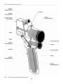
CONTENTS
SAFETY
1
SYSTEM TROUBLESHOOTING
GUIDE
CHART
26
PROBLER GUN
ILLUSTRATION
AIR PASSAGE & THREAD ILLUSTRATION
DAILY START-UP
DAILY SHUT-DOWN
SEAL and VALVE INTEGRITY TESTS
SEAL INSPECTION
CHAMBER DRESSING
PISTON THROW ADJUSTMENT
4
5
6
6
7
8
9
10
TROUBLESHOOTING GUIDE
11
ELECTRICAL TROUBLESHOOTING
GUIDE
HEATER FIREROD SPECIFICATIONS
THERMOCOUPLE SPECIFICATIONS
WATLOW ERROR CODE CHART
GENERATOR CONVERSION
28
28
29
29
Notes
30
LS GUN
ILLUSTRATION
INITIAL START-UP
SPRAY TECHNIQUE
DAILY SHUT-DOWN
EXTENDED SHUT-DOWN
14
15
16
17
17
MATERIAL PUMPS
19875-00 ILLUSTRATION
21835-00 IILUSTRATION
18
19
OVERHAUL PROCEDURE
TROUBLESHOOTING CHART
OVERPRESSURE SWITCH INSTALLATION
20
22
24
IF YOU HAVE AN EQUIPMENT
PROBLEM…
INSIDE BACK COVER
Basic Troubleshooting Guide__________________________________________________________
SAFETY
Operating Safely
Safe Handling And Use
of Urethane Foam Equipment
In operating urethane foam equipment safely, user should make
every effort to:
1. Handle chemicals safely.
2. Provide adequate ventilation.
3. Provide adequate safety equipment (gloves, respirators, safety
glasses, protective clothing, etc.) for operators and all others working
in areas where they may be exposed to the chemicals or their vapors.
4. Avoid operating equipment which has given any indication of
malfunction.
5. Become fully acquainted with the equipment and chemicals used.
Introduction
Any tool, if used improperly, can be dangerous. Safety is
ultimately the responsibility of those using the tool. In like manner, safe
operation of polyester processes is the responsibility of those who use
such processes and those who operate the equipment. This manual
outlines procedures to be followed in conducting polyester operations
safely.
All personnel involved in dispensing operations should read and
understand this manual. It is most important that equipment operators,
maintenance and supervisory personnel understand the requirements
for safe operation.
This manual cannot answer every circumstance; each user
should examine his own operation, develop his own safety program
and be assured that his equipment operators follow correct
procedures. Glas-Craft hopes that this manual is helpful to the user
and recommends that the precautions in this manual be included in
any such program.
Urethane foam systems are comprised of several different
chemical compounds, some of which may be hazardous if improperly
used.
Handling Chemicals Safely
Storage of polyisocyanates, diamines, and organic solvents
should be isolated and restricted to specially constructed storage
rooms. Store chemicals in original containers and according to
manufacturer's recommendations listed on the container. Maximum
ambient temperatures to which such chemicals should be exposed are
specified by the manufacturer and MUST NOT be exceeded either in
the storage area or in the spraying or pouring area.
To avoid moisture contamination, do not open containers until
ready for use. After use, the remaining material should be re-sealed in
the original container and stored in areas away from moisture.
During clean-up of spilled isocyanate-component, respirators,
gloves and eye protection must be worn. Isocyanates which have been
spilled can be controlled by covering them with dry saw dust and/or
other absorbent inert materials. Care should be taken to avoid skin
contact. The absorbent material and the absorbed isocyanate should
be collected promptly, placed in an open-top container, and treated
with dilute solutions of ammoniom hydroxide and/or alcohol. While
being treated in this manner, the material should be in an adequately
ventilated area. Clothing on which any material has been spilled
should be removed immediately, and cleaned before being worn again.
CAUTION
Particular caution must be taken with respect to the vapors
released during the use of urethane foam systems.
Isocyanate compounds are used in urethane foaming operations. The
medical history of persons who may be exposed to such isocyanates
should be examined. It is recommended that individuals with a history
of chronic respiratory ailments should avoid exposure to all
isocyanates.
In addition to the manual, Glas-Craft recommends that the user
consult the regulations established under the Occupational Safety &
Health Act (OSHA), particularly the following sections:
1910.94
Pertaining to ventilation.
1910.106 Pertaining to flammable liquids.
1910.107 Pertaining to spray finishing operations, particularly
Paragraph (m) Organic Peroxides and Dual Component Coatings.
Local codes and authorities also have standards to be followed in
the operation of your spraying equipment. Chemical manufacturer's
recommendations should be obtained and considered. Your insurance
carrier will be helpful in answering questions that arise in your
development of safe procedures.
Clean-Up Solvents
WARNING
A hazardous situation may be present in your pressurized fluid
system!
Halogenated Hydrocarbon Solvents can cause an explosion when
used with aluminum or galvanized components in a closed
(pressurized) fluid system (pumps, heaters, filters, valves, spray
guns, tanks, etc.).
Personnel Safety Equipment
The explosion could cause serious injury, death and/or
substantial property damage.
Glas-Craft recommends the following Personal Safety
Equipment for conducting safe operations of the Polyester Systems:
Cleaning agents, coatings, paints, etc. may contain Halogenated
Hydrocarbon Solvents.
Some Glas-Craft spray equipment includes aluminum or
galvanized components and will be affected by
Halogenated Hydrocarbon Solvents.
EYE
PROTECTION
HEARING
PROTECTION
BREATHING
PROTECTION
A. There are three key elements to the Halogenated Hydrocarbon
(HHC) solvent hazard.
1. The presence of HHC solvents. 1,1,1-Trichloroethane
and Methylene Chloride are the most common of these solvents.
However, other HHC solvents are suspect if used; either as part
of paint or adhesives formulation, or for clean-up or flushing.
2. Aluminum or Galvanized Parts. Most handling
equipment contains these elements. In contact with these metals,
Glas-Craft recommends that the user consult the state and local
regulations established for all Safety equipment listed.
1
Basic Troubleshooting Guide__________________________________________________________
HHC solvents could generate a corrosive reaction of a catalytic
nature.
3. Equipment capable of withstanding pressure. When
HHC solvents contact aluminum or galvanized parts inside a
closed container, such as a pump, spray gun, or fluid handling
system, the chemical reaction can, over time, result in a build-up
of heat and pressure, which can reach explosive proportions.
When all three elements are present, the result can be an
extremely violent explosion. The reaction can be sustained with
very little aluminum or galvanized metal: any amount of
aluminum is too much.
B. The reaction is unpredictable. Prior use of an HHC solvent
without incident (corrosion or explosion) does NOT mean that such
use is safe. These solvents can be dangerous alone (as a clean-up or
flushing agent) or when used as a component of a coating material.
There is no known inhibitor that is effective under all circumstances.
Furthermore, the mixing of HHC solvents with other materials or
solvents, such as MEK, alcohol, and toluene, may render the inhibitors
ineffective.
C. The use of reclaimed solvents is particularly hazardous.
Reclaimers may not add any inhibitors, or may add incorrect amounts
of inhibitors, or may add improper types of inhibitors. Also, the possible
presence of water in reclaimed solvents could feed the reaction.
D. Anodized or other oxide coatings cannot be relied upon to prevent
the explosive reaction. Such coatings can be worn, cracked,
scratched, or too thin to prevent contact. There is no known way to
make oxide coatings or to employ aluminum alloys, which will safely
prevent the chemical reaction under all circumstances.
E. Several solvent suppliers have recently begun promoting HHC
solvents for use in coating systems. The increasing use of HHC
solvents is increasing the risk. Because of their exemption from many
State Implementation Plans as Volatile Organic Compounds (VOC's),
their low flammability hazard, and their not being classified as toxic or
carcinogenic substances, HHC solvents are very desirable in many
respects.
F. Consult your material supplier to determine whether your solvent
or coating contains Halogenated Hydrocarbon Solvents.
G. Glas-Craft recommends that you contact your solvent supplier
regarding the best non-flammable clean-up solvent with the heat
toxicity for your application.
H. If, however, you find it necessary to use flammable solvents, they
must be kept in approved, electrically grounded containers.
I.
Bulk solvent should be stored in a well-ventilated, separate
building, 50 feet away from your main plant.
J. You should allow only enough solvent for one day's use in your
laminating area.
K. "NO SMOKING" signs must be posted and observed in all
areas of storage or where solvents and other flammable materials
are used.
L. Adequate ventilation (as covered in OSHA Section 1910.94 and
NFPA No. 91) is important wherever solvents are stored or used, to
minimize, confine and exhaust the solvent vapors.
M. Solvents should be handled in accordance with OSHA Section
1910.106 and 1910.107.
Toxicity of Chemicals
A. Glas-Craft recommends that you consult OSHA Sections
1910.94, 1910.106, 1910.107 and NFPA No. 33, Chapter 14, and
NFPA No. 91.
B.
Contact your chemical supplier(s) and determine the toxicity
of the various chemicals used, as well as the best methods to prevent
injury, irritation and danger to personnel.
C.
Also determine the best methods of first aid treatment for
each chemical used in your plant.
First Aid
If chemicals containing isocyanates are splashed on the skin,
they can produce ill effects. Steps to counteract such effects should be
started immediately.
1. Apply Tincture of Green Soap, full strength, to the contaminated
area. If Tincture of Green Soap is not immediately available, wash the
exposed area repeatedly with soap and water. Soap and water is not
as desirable as using Tincture of Green Soap because many
isocyanate components are not easily dissolved in water. In addition,
soap and water does not form a barrier to the isocyanates.
2. After approximately two to four minutes, wash off the Tincture of
Green Soap with water. If there is still an indication of isocyanate
present, repeat the application. If the isocyanate contamination is on
the facial area, care must be taken to avoid getting the Tincture of
Green Soap in the eyes.
3. If the person develops breathing difficulties, oxygen should be
administered. Quite often the exposed person will experience residual
effects such as coughing spells. CONTACT PHYSICIAN
IMMEDIATELY.
WARNING
If you are now using Halogenated Hydrocarbon solvents in
pressurized fluid systems having aluminum or galvanized wetted
parts,
IMMEDIATELY TAKE THE FOLLOWING STEPS:
> Empty system, shut-off, completely depressurize in
accordance with equipment service instructions.
> Remove equipment from service, disassemble in accordance
with equipment servicing instructions.
> Inspect all parts for corrosion and/or wear. Replace any
damaged parts.
> Thoroughl y clean all parts of the equipment with a nonhalogenated solvent and reassemble in accordance with
equipment servicing instructions.
> Flush equipment with non-halogenated solvent.
> Do NOT reuse equipment with HHC solvents or with
materials containing such solvents.
> Material suppliers and/or container labels should be
consulted to ensure that the solvents used are compatible with
your equipment.
WARNING
Contact a doctor immediately in the event of an injury and give
him the information you have collected. If your information
includes first aid instructions, administer first aid immediately
while you are contacting the doctor.
4. If a person accidentally swallows isocyanates, large amounts of
water should be swallowed immediately. Vomiting should then be
induced by patient sticking his finger down his throat, or by swallowing
large quantities of warm salt water or warm soapy water. After
vomiting, more water should be taken to dilute isocyanate further.
CONTACT PHYSICIAN IMMEDIATELY.
NOTE
Glas-Craft is aware of NO stabilizers available to prevent
Halogenated Hydrocarbon solvents from rea ction under all
conditions with aluminum components in a closed fluid system.
TAKE IMMEDIATE ACTION...
Halogenated Hydrocarbon solvents are dangerous when used
with aluminum components in a closed fluid system.
2
Basic Troubleshooting Guide__________________________________________________________
MUST use an approved (U.S. Bureau of Mines) fresh air supplied
respirator.
Respirators should be regularly inspected, cleaned and
disinfected according to good practices. Records must be kept of the
inspections. The user MUST have a medical clearance indicating that
he can safely use a respirator.
Respirators must fit securely; beards prevent a tight seal around
the face. Eye glasses have to be given special attention and contact
lenses are prohibited.
Safety goggles, gloves and other protective devices are
suggested for operators of foaming equipment. Refer to OSHA
Standards, sub-part 1, 1910.132, 1910.133 and 1910.134 for Federal
standards.
Ventilation
WARNING
Hazardous concentrations of some chemical vapors exist before
they can be smelled. Chemical component suppliers should be
contacted to determine at what concentrations the vapors of the
chemicals they supply become dangerous, and the procedures
and equipment needed to detect such dangerous concentrations.
Such equipment should be obtained.
Adequate ventilation must be provided in any area where foam
chemicals are sprayed or poured, and wherever the material
containers are opened.
IF YOU HAVE ANY QUESTIONS REGARDING THE ABOVE
PRECAUTIONS
OR
ANY
SERVICE
OR
OPERATION
PROCEDURES, CALL YOUR GLAS-CRAFT DISTRIBUTOR OR
GLAS-CRAFT, INC.
In industrial applications, foaming operations should be restricted
to specific areas, and proper ventilation should be provided in these
areas to prevent chemical vapors from spreading. Spray foaming
operations MUST be restricted to a spray booth where a minimum
exhaust of 100 feet per minute at the face of the booth is provided.
Special care should be taken to prevent unsuspecting personnel both
inside and outside of the plant from being exposed to chemical vapors.
The chemical vapors should be exhausted to atmosphere in such a
manner and at a sufficiently low concentration that personnel outside
the plant are not exposed to dangerous concentrations of chemical
vapors. Refer to OSHA Standards, sub-part G, 1910.107 and
particularly sub-section (m) for Federal standards. State and local
authorities may have applicable statutes or regulations concerning
ventilation.
n contractor applications (for example, at a construction site,
inside building or other enclosed space), the forced ventilation
normally provided is likely to be inadequate. These applications,
therefore, usually REQUIRE the use of forced, fresh air respirators for
all persons in the areas where foaming operations are conducted or
where the chemical vapors are likely to spread.
Notice
All statements, information and data given herein are believed to be
accurate and reliable but are presented without guaranty, warranty or
responsibility of any kind expressed or implied. The user should not
assume that all safety measures are indicated or that other measures
are not required.
5845 WEST 82nd STREET, SUITE 102
INDIANAPOLIS, INDIANA 46278 U.S.A.
In industrial and contractor applications, it is advisable to run
frequent tests to determine the exact concentration of isocyanate
vapor in the air. Industrial equipment is available for making such
determinations. Your chemical supplier can recommend such
equipment and procedures.
PHONE (317) 875-5592
FAX (317) 875-5456
APRIL 1996
Proper Safety Equipment
All persons spraying or working is areas where forced air
ventilation is not adequate to remove isocyanate vapors from the air
3
Basic Troubleshooting Guide__________________________________________________________
PROBLER GUN
4
Basic Troubleshooting Guide__________________________________________________________
Note:
All fractional dimensions recorded in inches.
5
Basic Troubleshooting Guide__________________________________________________________
DAILY START-UP
DAILY SHUT-DOWN
1.
2.
3.
4.
5.
6.
Seal and Valve Integrity Test (SVI)
1. Perform tests on gun
a. Side Block Seal Integrity test - With ball valves
in the on position, turn off gun air slide valve
for 15-20 sec. - now slide air valve back open
and note if any material is purged out. If so,
replace side block seals.
b. High Pressure ball valve test - Turn off
material valves, trigger gun several times.
Turn off air slide valve for 20-30 seconds. Now
turn on air slide valve and trigger gun several
times, checking for leaks. Correct leak if
necessary.
2. Switch all circuit breakers to the off position.
3. Turn off main air supply.
4. Apply Nitrogen blanket to drums of material.
5. Close material ball valves.
6. Remove side blocks from Probler gun and inspect
seals for nicks or scratches. Replace if
questionable.
7. Pack the head and slide ports of gun with
generous amounts of high quality lithium or
lubriplate then reconnect the side blocks. MR-515
aerosol is also acceptable for this operation.
Unwind hose.
Check nitrogen blanket or air dryer.
Check all lube reservoirs or felt wiper assemblies.
Check all material screens
Pressurize material transfer system.
Adjust main air regulator pressure to desired
setting (60-100 PSI).
7. Switch on main power, primary and hose heater
circuit breakers and make appropriate settings.
8. Open air slide valve on Probler gun which will
purge out grease from shut -down.
9. Open both material shut-off valves on Probler gun.
10. Ready to spray.
NOTE
A coat of lubricant on the gun will prevent overspray
build-up.
6
Basic Troubleshooting Guide__________________________________________________________
PROBLER GUN SEAL AND VALVE INTEGRITY TESTS (SVI Test)
CAUTION
CAUTION
Proper safety gear should always be worn during
operation and trouble shooting of the Probler Gun or any
Glas-Craft system.
Always wear safety goggles.
Material is under pressure and can cause injury. If you
have questions, call your authorized distributor or GlasCraft for assistance.
Never look down the nozzle barrel. Always observe
nozzle from the side. Never point the Probler Gun at a
person.
1.
2.
Side Block Seal Integrity Test (side block seal
16811-01 or T4 -132). This test will determine if the
side block seal assemblies are leaking (side block
seal assembly #17275-00).
a. With material ball valves in the on position,
turn off the air slide valve and wait for 15-20
seconds (material ball valves PG-15, air slide
valve assembly #16832-00).
b. Turn the air slide valve on and watch the
nozzle for A or B material. If material is
observed, turn to Probler Gun Seal Inspection,
section 5.
NOTE
Some air compressors will build up condensation
(moisture) in certain ambient conditions.
This
condensation can build up and blow out of the gun
nozzle, resembling a material leak. Hold a rag in front of
the gun, or point gun at a surface with a rag on it before
turning the slide valve to the on position. This will make
it easier to determine if it is A material, B material or
condensation. If condensation is observed, an air dryer
should be used between the air supply and the inbound
air fitting on the system.
7
Ball Valve Integrity Test
a. Turn material ball valves to the off position,
and trigger gun several times (material valves
#PG-15). Turn off air slide valve and wait 20-30
seconds (air slide valve assembly 16832-00).
b. Now turn on air slide valve and observe nozzle
for leaking material, triggering gun several times.
If material is observed, tighten valve packing on
the appropriate valve (see section 8, question 9).
Basic Troubleshooting Guide__________________________________________________________
PROBLER GUN SEAL INSPECTION
4.
When the Probler Gun SVI Test (Seal and Valve
Integrity) shows that the seals are leaking, it must be
determined where the leak originates to return the gun to
normal operation. See Section 4, “Seal and Valve
Integrity Test”.
There are four places where the gun can leak:
1. The side block seal (seal 16811-01 or T4 -132).
This is the main wear part in the gun, and is the
first place to look. If the seal is scratched or
damaged, replace with a new seal.
2. The mixing chamber surface (mixing chamber
17637-xx or18375-xx). The side block seal
seats against the flat mixing chamber surface.
Inspect mixing chamber surface for scratches,
and inspect the side ports in the mixing chamber
for a raised burr or lip. If either is observed,
refer to Chamber Dressing, section 6. The
chamber must be properly dressed before
continued operation.
3. a. The inside surface of the side block seal
housing (housing 16812-00). If the side block
seal and the mixing chamber both look good,
remove the side block seal from the side block
seal housing and inspect the inside diameter
surface of the housing. This is a honed surface.
If it is scratched, it must be replaced. Scratches
here are most likely from cleaning with a sharp
object.
b. Build up can also accumulate on this inside
diameter surface where the seal seats (housing
16812-00). This can cause the seal to seat
improperly with poor seal compression against
the mixing block surface. Carefully clean this
area and replace the seal. If build up is
excessive, consider soaking housing in a
suitable cleaning solution.
The check valve ball seat can become cracked if
the side block seal housing is tightened down too
far (seat #16810-00, check ball #16808-00, side
block seal housing #16812-00). This will allow
material to leak between the threads of the side
block seal housing and the side block body (side
block seal housing #16812-00, side block body #T4 144 or T4 -143).
Reassembly…
Replace the check valve assembly into the side block
body (assembly consists of the #16809-00 ball
spring, #16810-00 check valve ball seat and
#16808-00 check ball. Side block body #T4-144 or
#T4-143).
Before replacing the side block seal housing into the
side block body, make sure all threads are clean and
be sure not to over-tighten. (side block seal housing
#16812-00, side block #T4 -144 or #T4 -143).
Replace side block seal housing with side block seal and
compression spring into the side block body (side
block seal housing #16812-00, side block seal
#16811-01 or #T4-132, compression spring, #1682300, side block body #T4-144 or #T4-43). This
housing should be tightened to a snug fit, but no
further.
NOTE
The seal housing seats against the shoulder of the
check valve ball seat. If the seal housing is tightened
down too far it will crack the check valve ball seat,
causing a material leak between the threads of the side
block seal housing and the side block body (seal
housing #16812-00, check valve ball seat #16810-00,
side block seal housing 16812-00, side block body T4144 or T4-143).
8
Basic Troubleshooting Guide__________________________________________________________
CHAMBER DRESSING
The Probler mixing chamber can become scratched or
burred during normal use (chamber #17637-xx or
#18375-xx ). This can cause a mist of A or B material to
come out of the gun nozzle during the air purge.
Causes:
a. Mixing chamber develops a lip or burr on the
side port. Normally this happens from improper
cleaning with a drill bit.
b. Scaring along the side of chamber body from
were the side block seal rides against the
chamber, normal use (seal 16811-01 or T4-132).
NOTE
When dressing the mixing chamber, it is important to
use a flat surface to sand against. Hand sanding can
result in an uneven chamber surface that will not seal
properly.
Side block seals (16811-01 or T4-132)
The chamber can be reconditioned for use.
On a flat surface, put a piece of 1200 grit wet / dry
sandpaper with some light weight general purpose oil.
Dress the chamber with 1200 grit sand paper by sanding
against the flat surface until lip and / or scaring has been
removed.
Inspect chamber by shining a light through side port and
looking down snout for debris.
( a. )
NOTE
a.
Be sure to use proper size drill bit for cleaning the snout
and side ports. Refer to Probler Gun user manual.
b.
9
( b. )
Seal shows signs of scaring from lip on mixing
chamber. The cut or groove is consistent from
through port in seal to outer edge.
Seal shows signs of normal wear from
triggering gun and material pressure, most
normally seen on materials with heavy fill or
pigment. Groove will be deep and wide at the
through port, and taper out towards the edge of
the seal body.
Basic Troubleshooting Guide__________________________________________________________
PISTON THROW ADJUSTMENT
The Probler Gun piston throw is factory set, and as a
rule should not require adjustment. The piston throw
refers to how far back the air piston will travel when the
gun is triggered (air piston assembly 16820-00). A
proper throw adjustment will align the mixing chamber
side ports with the side block seal ports, allowing
material to flow out the nozzle when the gun is triggered
(mixing chamber 17637-xx or 18375-xx, side block seals
16811-01 or T4 -132). There is a set screw that
determines how far the piston will travel before it stops
(set screw 17259-16F).
7.
8.
9.
10.
11.
To determine if the throw is correct:
1. Turn material ball valves to the off position (valves
PG-15)
2. Turn off the air slide valve assembly (valve 1683200)
3. Remove side blocks from gun (side blocks T4 -143
and T4-144)
4. Remove one of the side block seal housings from
the side block (assembly 17275-00, side block T4 143 or T4 -144)
5. The housing will have the side block seal in it
(housing 16812-00, seal 16811-01 or T4 -132). This
piece (housing with seal) will be put into the front
gun housing to determine if the mixing chamber
port is lining up with the side block seal port
(housing 16812-00 placed in front gun housing
16800-00). When the gun is triggered, the mixing
chamber should line up with the port in the side
block seal (seal 16811-01). See drawings.
6. Turn on the air slide valve and trigger the gun. This
will draw the piston back. The mixing chamber side
port (hole in the side of the mixing chamber) should
line up in the center of the hole in the side block
12.
13.
14.
seal where it is inserted into the front housing (side
block seal 16811-01, housing 16800-00). (See Fig.
1)
If the port does not line up, the piston throw must
be adjusted.
Turn slide valve off.
Remove the cover screw on the back of the air
piston cap (cover screw 16858-16F, air piston cap
16802-00). This will expose the set screw (set
screw 17259-16F).
Remove the set screw and clean with solvent.
Using a non-permanent thread lock on the set
screw threads, replace the set screw in the air cap
close to the desired depth. (Use blue Loc-Tite or
another similar product.)
Turn the air slide valve back on and trigger the gun.
Adjust the set screw until the side block seal port
and the mixing chamber port line up when the gun
is triggered.
Allow the thread sealer to set.
Return gun to operation.
NOTE
If there is no air to the gun the piston throw can still be
adjusted. Remove the air cap and take out the return
spring, replacing the air cap (air cap 16802-00, return
spring 16865-00). The air piston can now be moved
manually to the trigger position. When piston throw is
adjusted, replace the return spring.
10
Basic Troubleshooting Guide__________________________________________________________
PROBLER GUN TROUBLESHOOTING GUIDE
1
Why did the clip ring on the
air piston inside the Probler
Gun break (clip ring #1682801) ?
2
When gun is air purging, I see
a mist of ISO (or Poly)
coming out the nozzle with
the purge air. Why and what
should be done?
3
I keep cutting side block seals
(16811-01 or T4-132 seals)
soon after installation. Why?
4
There are sharp edges on the
side ports of the mixing
chamber (mix chamber
17637-xx or 18375-xx). How
do I remove them?
a. Check air pressure to gun. Too much air pressure (over 100psi) can
break the clip ring. Regulate gun pressure to 90-100 psi at 10 CFM
b. Mixing chamber nozzle was pushed forcefully towards gun body,
breaking the clip ring. Causes are dropping the gun or improperly
forcing the gun to trigger.
NOTE…
If Probler Gun will not trigger and gun has required air supply, DO NOT
force chamber back into gun to “break it free”. This will result in costly
damage to the gun and is the result of poor maintenance or improper
shutdown procedure. The Gun needs to be taken apart and properly
cleaned.
a. Side block seal is leaking (16811-01 or T4 -132 seal). Remove seal
assembly #17275-00 and inspect seal, chamber and seal housing (see
seal inspection, section 5).
NOTE…
A raised, sharp edge on the side port of the mixing chamber can
damage the seal (mixing chamber 17637-xx or 18375-xx, seal 1681101 or T4-132). See chamber dressing, section 6.
NOTE…
When replacing a seal, be sure to inspect the inside of the seal
housing (housing 16812-00). If there is build up or contamination it
can keep the seal from seating properly.
a. Check the mixing chamber for burrs or scratches (mixing chamber
17637-xx or 18375-xx). See chamber dressing to recondition mixing
chamber.
NOTE…
If a drill bit is used to clean the side ports of the mixing chamber, a burr
can form on the mixing chamber side port. Always inspect the mixing
chamber surface after cleaning with a drill bit. It is important to insert
the drill bit into the mixing chamber side port as straight as possible.
Using an angle, other than 90°, can raise an edge on the side port.
NOTE…
The air purge will clean the chamber, but A and B materials can begin
to scale on the side of the mix chamber after continual use. This
needs to be cleaned periodically. If build up continues it can become
hardened and damage the seals. See chamber dressing, section 6.
a. See Chamber Dressing, section 6.
NOTE…
Cleaning the side port with a drill bit most likely causes this. Always
inspect mixing chamber surface after cleaning with a drill bit.
Attempt to insert drill bit straight into side port holes.
Going in at an angle can raise an edge.
11
Basic Troubleshooting Guide__________________________________________________________
5
There is air to the gun, and
air purge is good. When gun
is triggered, the piston is
sluggish to retract or doesn’t
move. Why?
6
When the side blocks are
removed, there is a material
build-up around the chamber
and where the chamber
passes through the gun head.
Why and what to do about it?
All the air passages in the
Probler were foamed up
(crossed-over). Why and
how are they cleaned out?
7
8
9
10
11
The mixing chamber does not
line up with the holes in the
side block seals when the
gun is triggered. Why, and
how are they lined up
correctly?
The high pressure ball valves
on the Probler seem loose
and may be leaking (valves
PG-15). How do I fix them?
The mixing chamber is not
smooth and is built up with
material. How is it fixed?
There are scores on the mix
chamber. Why and how are
they fixed?
a.
The mixing chamber slides through a guide channel in the front
housing of the Probler Gun (housing 16800-00). Remove side blocks
(side blocks T4-144 and T4-143) and front housing (housing 1680000). The mixing chamber should be able to slide freely through the
guide channel. Inspect and clean if needed.
b. Air starvation. Make sure that the gun is being supplied with 10 CFM
at 100 psi.
c. Air starvation. If the gun has the required air supply, check the internal
air passages in the Probler Gun body. If gun was recently crossed
over (crossed over = cured foam in the internal air passages), the
vertical passage elbow is most likely restricted. Clean out the air
passages with proper sized drill bits (see diagram of Probler Gun air
passages).
d. The air piston in the back of the gun needs to be well lubricated with
white lithium grease. If this area is dry, o-rings can dry out and make
for sluggish trigger actuation.
a. Build up is caused by leaking side block seals and / or ball valves
(seals 16811-01 and T4-132, ball valves PG-15). See seal inspection.
b. Gradual scaling of material on the sides of the mixing chamber is a
normal occurrence. See Chamber Dressing, section 6. When cleaned
periodically this creates no problem. More frequent gun inspection /
cleaning will correct the condition.
a. The high pressure ball valves were not closed when the bolts holding
the side blocks were loosened, causing material to fill the internal gun
chambers (ball valves PG-15, side blocks T4-144 and T4-143, bolts
9944-48C).
b. Total seal failure (seal 16811-01 or T4 -132). This is rare and can be
avoided with proper gun maintenance and timely seal replacement.
NOTE…
To clean the gun, take apart, drill out internal passages and soak in a
suitable cleaning solution.
a. The piston throw set screw (replace) is out of adjustment and needs to
be reset (nut 17259-16F). See resetting Piston Throw Adjustment,
section 7.
NOTE…
The piston throw is factory set, and should not be accessed unless the
piston is out of adjustment.
a. Tighten valve packings. Remove valve handles by loosening allen
screws and pulling handles off. This will expose the ball valve packing
flats. With a wrench, tighten the packings to snug. Reassemble the
gun and perform ball valve seal integrity test (see Ball Valve Seal
Integrity Test, section 4.)
a. With a new razor blade, shave the mixing chamber surface (mixing
chamber 17637-xx or 18375-xx). Be careful not to scratch the surface.
If the surface is scratched, see Chamber Dressing, section 6.
NOTE…
Be careful that your cleaning does not damage the mixing chamber. If
build up is severe, consider soaking in a suitable cleaning solution
before shaving.
a. Abrasive filler can cause this. Try Glas-Craft hardened mixing
chambers for longer life (mixing chambers 17637-G-xx or 18375-G-xx).
b. Hardened material on the seal surface can cause this (seal 16811-01
or T4 -132). See shutdown procedures.
c. Improper cleaning can cause this.
See chamber dressing to recondition mixing chamber, section 6.
12
Basic Troubleshooting Guide__________________________________________________________
12
13
14
15
16
17
When a new side block seal
is put in material seeps
around the shoulder of the
seal between the seal and
housing. Why and how do I
fix it?
The piston rod is bent. What
causes this?
The Probler continuously
leaks air from the bottom of
the handle. Why?
There is air leaking from the
trigger button (trigger button
PG-16). Why?
There is air leaking from the
trigger retaining nut (nut
16839-00). Why?
There is air leaking around
the side block and gun head.
Why and how to stop it?
18
When the gun is triggered,
the purge air stays on. Why
and how is it stopped?
19
There is air leaking from the
air on / off slide valve (slide
valve 16832-00 assembly).
Why and how is it fixed?
The Probler is leaking air
from between the gun body
and the front housing (gun
body 16867-00 and housing
16800-00). Why and how is it
fixed?
20
a. The honed inside of the seal housing is scratched (housing 16812-00).
Replace housing.
NOTE…
The scratch is most likely from a previous cleaning with a sharp object.
Use care when cleaning this housing. The inside surface is honed to
give a high pressure seal to the shoulder of the seal (seal 16811-01 or
T4-132, housing 16800-00).
b. There is material build up on inside of seal housing and it is not letting
the seal seat properly (housing 16812-00). Soak housing in a suitable
cleaning solvent to remove build-up. Be careful not to scratch the
inside surface when cleaning, see Seal Inspection, section 5.
a. The gun was dropped.
b. The gun mix chamber was improperly forced towards the gun body by
means of a hammer or pushing the nozzle against a solid surface.
a. The middle o-ring on the trigger assembly is cut (o-ring 7554-53,
trigger T4 -171). Replace o-ring.
c. The trigger adjustment nut is out too far (nut 16839-00). Adjust by
tightening nut until leaking stops.
NOTE…
If the trigger nut is adjusted out too far it will not allow the spring return
to shuttle the trigger spool to its normal position. If the trigger nut is
adjusted in too far, the gun will not trigger properly.
a. The front o-ring on the trigger assembly is cut and needs to be
replaced (o-ring 7554-53, trigger assembly T4-171).
a. The back o-ring on the trigger assembly is cut and needs to be
replaced (o-ring 7554-53, trigger T4-171).
a. There is material build up on the side blocks and / or the front housing
of the gun (side blocks T4-144 and T4-143, housing 16800-00). Using
a new razor blade, shave off the build up. Finish with a fine grit wet /
dry sandpaper (1,200 or finer grit).
a. An o-ring on the air piston is cut or damaged and needs to be replaced
(o-ring 7554-03, 7554-05 or 7554-29). Remove air piston assembly
and replace damaged o-rings (Air piston assembly 16820-00).
This can be caused by a scar in the air passage, debris in the air
passage or solvent contamination causing the o-ring to swell and be
cut during operation.
a. The slide valve o-rings are cut or damaged and need to be replaced
(o-rings 7554-09).
a. The o-ring that seals between these two parts is damaged and needs
to be replaced (o-ring 7554-12).
13
Basic Troubleshooting Guide__________________________________________________________
LS Gun
7959-20C
7554-03
23709-00
Shoulder Screw
Needle
O-Ring
23702-00
23708-00
23703-00
23710-00
Adjusting Air
Needle
Gun Coupling
Nut
23730-00
Air Cap
23729-00
Cylinder
Atomizing Air Ring
8212-16F
23728-00
Shoulder Screw
Retaining Ring
7554-04
7554-29
8212-20F
O-Ring
23707-00
O-Ring
7554-04
Piston Shaft
23704-00
7554-05
23735-01
O-Ring
ISO Check Valve
Filter Assy.
23734-00
Spring
Machine Screw
O-Ring
23721-00
Front Head
Teflon W asher
23706-00
16808-00
Rear Cap
17259-16F
7716-08C
Set Screw
Set Screw
7554-04
O-Ring
Ball Assy.
23712-00
13867-08
Packing Nut
O-Ring
23716-00
23711-00
23705-00
8560-23
7729-07
Air Piston
Filter Insert
Packing Washer
9869-19
Spring
23735-00
Elbow Fitting
Lock Nut
Fitting
16809-00
20984-01
Shoulder Screw
23717-00
POLY Check Valve
Filter Assy.
23733-00
Spring
Filter Screen
13867-11
21208-08C
O-Ring
Machine Screw
23713-00
23714-00
23715-00
Handle Insert
Filter Housing
Trigger Piston
23720-00
7554-16
20086-01
Stainless Steel
Tubing
O-Ring
Slide Valve
13867-28
1880-00
Replacement O-Ring
(NOT SHOW N)
Fitting
23701-00
17597-07
PG-18
Trigger
Straight Fitting
21208-08C
Machine Screw
PG-15
2-Way Ball Valve
Gun Hnadle
PG-13
Connector Fitting
23731-00
Guard
23739-00
21208-08C
SST. Dowel Pin
Machine Screw
23724-00
23723-00
Round Spray Mixing
Seal
Flat Spray
Seal Housing
23727-00
Flat Spray Tip
23725-00
Round Spray Seal Housing
Round Spray Tip
23722-00
23722-01
.023
.037
23726-00
23726-01
23737-00
Round Spray Kit
14
.013
.018
Flat SprayMixing
Seal
23736-00
Fla t Spra y Kit
Basic Troubleshooting Guide__________________________________________________________
INITIAL START-UP
With all material and air lines connected and power
cable attached, the system is now ready for start-up.
3.
Dispose of waste material properly and in
accordance with chemical suppliers instructions and
local, state and federal regulations.
1.
Remove the Gun from the hoses by loosening
and removing the nut and ferrule, P/N 17597-01 forward
of the PG-15.
4.
Clean nuts and ferrules before reassembly.
Make sure both fittings are tight and secure.
2.
Place separate clean containers under each
individual Ball Valve. With only the transfer pumps
operational, open each ball valve simultaneously to allow
trapped air to escape the hoses and material to flow into
the containers until all air is purged from the material
system. Close ball valves
5.
Slide Air Valve forward and turn Ball Valves on.
(See figure3.)
6.
The system is now ready for operation.
NOTE
Remember to dispense one to two gallons of material to
clear the system of grease and plasticizer that was used
during factory testing.
WARNING
Do not place any part of the body in the path of the
material spray.
Do not point the gun at or near other personnel.
Do not look into the Mixing Chamber orifice at any time.
Because of the hazardous materials used in this
equipment, it is recommended that the operator use an
air mask, goggles, protective clothing, and other safety
equipment as prescribed by current regulations,
recommendations of the chemical suppliers, and the
laws in the area where the equipment is being used.
15
Basic Troubleshooting Guide__________________________________________________________
SPRAY TECHNIQUE
1.
Viscosity of the material being sprayed directly
correlates with thickness of the end product. In other
words the thinner the material the thinner the
material thickness.
2. The thicker the viscosity of the material is, the more
heat will be required to achieve a proper spray
pattern and thickness of material.
3.
4.
5.
We can also adjust individual material heat to adjust
unbalanced pressures. For example if one material
has a viscosity of 1200 and the other material has a
viscosity of 200, the material pressures between the
two will not be exact, but we can adjust the higher
temperature to the more viscous material and less
heat to the less viscous material to achieve a more
balanced pressure between the two.
Pressure of the material being sprayed directly
correlates with the shape of the spray pattern and
can affect the thickness of the part being sprayed.
6.
Taking these two factors into consideration and
consulting with the material manufacture we should
be able start with a preset heat setting and material
pressure setting. (Further adjustments to both
pressure and heat may be required).
7.
It may be necessary to purge the cold viscous
material. This is most easily achieved by removing
the material delivery tubes from the gun (PN 2372000)
8.
With the air containment needle valve completely
closed, purge the cold material from the unheated
section of hose.
9.
Within a few seconds the spray-pattern will begin to
open-up. Once the pattern opens to its optimal
spray-pattern, open the air containment needle valve
to achieve the proper atomization and pattern width.
10. The spraying of a waxed test panel is recommended
not only for material thickness testing, but also for
testing material quality.
Typically the higher the material-pressure the wider
the pattern. The wider the pattern the more atomized
the material, resulting in less mil thickness.
16
Basic Troubleshooting Guide__________________________________________________________
DAILY SHUT-DOWN
spray-tip (23726-00 Round 23727-00 Flat) and
retaining nut (23728-00 and tighten to 100 in. lbs.
Release main trigger. (see fig 2)
WARNING
Before attempting to perform any maintenance on this
Gun - Relieve All Fluid and Air Pressures!
To relieve fluid and air pressures:
1. Turn OFF all air supplies at System except Gun
Trigger Air.
2. Trigger Gun until all fluid pressures have been
relieved.
3. Turn OFF Gun Trigger Air at System.
1.
Remove air pressure from main proportional
pumps and transfer pumps.
2.
Pull trigger until all material pressure is removed.
3.
Turn Ball valves into the OFF position.
4.
Remove retaining cap (23730-00) and air cap
(23729-00) remove any over spray with solvent.
5.
Remove retaining nut (23728-00) and spray tip
(23726-00 Round) (23727-00 Flat) clean with
solvent.
6.
Rotate air containment needle clockwise until it
stops. (This action turns off the air containment).
7.
Pull main trigger back and release. The mixing
module will be pushed forward (23724-00 2372200 Round) (23725-00 23723-00 Flat)
Remove mixing module from needle. Clean side
ports with .011-inch drill.
8.
9.
13. Replace air cap (23729-00) and retaining cap
(23730-00).
EXTENDED SHUT-DOWN
This procedure should be performed when the system
is to be stored for an extended period of time (i.e.
winter shut-down, etc.)
1. Perform DAILY SHUT-DOWN PROCEDURE steps.
Push down on seal housing (23722-00 Round)
(23723-00 Flat) to expose holes. Clean side ports
with .025-inch drill. (See fig 1)
10. Clean front face and needle with solvent. Remove
any build-up on needle surface and check needle
tip for any wear or burrs.
11. Push seal housing (23722-00 Round) (23723-00
Flat) back up on mixing seal (23724-00 Round
23723-00 Flat.
12. Place mixing module onto the end of the needle
(23709-00) and pull main trigger back. Replace
17
Basic Troubleshooting Guide__________________________________________________________
19875-00 MATERIAL PUMP
18
Basic Troubleshooting Guide__________________________________________________________
21835-00 MATERIAL PUMP
19
Basic Troubleshooting Guide__________________________________________________________
MATERIAL PUMP OVERHAUL PROCEDURE
19875-00 (-01) Pumps
21835-00 Pumps
1.
NOTE
On P/N 21835-00 pumps, watch out for APS-119, APS128, & 19633-00. The 19633-00 will push these parts
out. Observe which side of the APS-119 comes out,
Keep right side up for diagnostics.
Dump pressure off system
WARNING
Be sure air and power are off to system.
This is achieved by splitting side blocks off of gun,
opening ball valves and purging materials into clean
containers.
2.
3.
Remove Valve Housing from the cylinder.
P/N UF-118 on 19875-00 pump.
P/N, 19634-00 on 21835-00 pump.
4.
Using a rubber mallet, tap shaft out through the
bottom of the cylinder, P/N 18219-00.
5.
Remove cylinder, P/N 18219-00 from Pump Head,
P/N 18227-00.
6.
Remove Cup Adapter, P/N 21440-00 from Pump
Head, P/N 18227-00.
Flush system side to be rebuilt with suitable solvent.
NOTE
This is optional, it makes the process easier.
3.
Disconnect inlet fitting from the bottom of the pump.
4.
Disconnect outlet fitting from the top of the pump.
DISASSEMBLE SUB-ASSEMBLIES
a. Systems with Over Pressure Valve: remove DIN
connector from switch, Phillips screw.
1. Cup Adapter, P/N 21440-00.
a. Remove Support Washer, P/N 18295-01.
b. Remove Over Pressure Switch from fitting.
b. Remove Seal, P/N 21595-00.
CAUTION
c. Remove Snap Ring, P/N 1005-02, Nylon Washer,
P/N 21896-01, & Felt Wipers, P/N 21897-01.
Do not immerse Over Pressure Valve in solvents
externally. (Flushing will not affect).
2.
5.
Remove pump from base.
a.
a) Remove P/N 21598-00, Transfer Seat from P/N
21597-00, Transfer Housing. Watch for P/N
APS-133, Ball and P/N 21803-00, Spring. The
Ball is loaded with spring tension.
Loosen and remove P/N 7729-10 Nylon Lock
Nut from yoke.
(Older MX Systems), loosen allen screw screw in
yoke, remove Hitch Pin, pull out Clevis Pin.
b.
b.
Loosen and remove four bolts, P/N 9945-48C.
PUMP DISASSEMBLY
1.
Loosen four nuts, P/N 7733-17 at the base of pump
and remove, break loose, in a criss-cross pattern.
2.
Remove Base, P/N P33-11 from Tie Rods, P/N
18289-00.
Shaft Assembly:
20
Remove FS-110, Piston Guide and P/N 2159500 Pump Seal.
Basic Troubleshooting Guide__________________________________________________________
CLEANING
1.
Thoroughly wash all parts in suitable solvent.
2.
If parts have any build-up of hardened material, it is
acceptable to polish parts with fine sand paper,(1200
grit) or steel wool(000).
3.
4.
Lubricate and install O-Ring, P/N 13867-43 on
bottom groove.
5.
Install P/N 18295-01 with lip facing toward P/N
21595-00 seal.
6.
Place P/N 21595-00 Seal and P/N FS-110 guide on
P/N 21597-00. The lips of the Seal will face away
from P/N FS-110.
6.
Set P/N 21803-00 Spring in P/N 21597-00 Housing
and set APS-133 Ball on Spring.
7.
Apply blue lock-tite to the threads of P/N 21598-00
and install on P/N 21597-00. Tighten these two
parts!
8.
Lubricate and install two P/N 13867-49 O- Rings on
P/N 18219-00 cylinder.
9.
Using a light weight non-detergent oil, coat the seal
on the shaft assembly and the walls of the cylinder,
then install the shaft assembly into the cylinder,
leave approximately 4” of the shaft exposed on the
top side.
It is recommended that the cylinder be honed with a
fine grit bead honer,(P/N RK5-2).
INSPECTION
1.
2.
3.
The Pump Cylinder, P/N 18219-00 inner wall should
be smooth. No pitting or scarring should be seen. If
slight scars show in the wall, they must not be able
to be felt with a finger nail.
The Pump Shaft, P/N 21599-00 must not have any
scoring, pitting, or build up of any debris on the
shaft.
Set the Ball, P/N APS-133 in the Seat, P/N 2159800 and hold up to a light. Observe for light between
seat surface and the ball.
10. Install cylinder/shaft assembly into P/N 18227-00
Pump Head, careful not to cut O-Ring for Pump P/N
21835-00.
NOTE
If a large sliver of light shows, check for debris or
scarring on Seat or Ball.
4.
11. With the Pump Assembly upside down, (easy if
clamped in a vise) install Foot Valve Housing P/N
19634-00.
P/N APS-128 & P/N APS-119 repeat the above step.
12. Set P/N 19633-00 Spring in place and set P/N APS128 Ball on Spring.
NOTE
The APS-119 is reversible, you can use either side.
13. Lubricate and install P/N 13867-44 O-Ring in groove
of P/N 19634-00.
14. Lubricate the outer edge of P/N APS-119 and set
top of ball, square and center flats of P/N APS-119
and P/N 19634-00.
RE-ASSEMBLE
NOTE
All parts underlined are contained in repair kit.
15. Gently set P/N P33-11 through P/N 18289-00 Tie
Rods and push down square and firm until it sets
down over cylinder O-Ring.
1.
Soak P/N 21897-01 in a light weight, non detergent
oil, then install in P/N 21440-00.
16. Continue holding P33-11 down, install (4) P/N 773412 Lock Washers and hand thread (4) P/N 7733-17
Nuts.
2.
Install P/N 21896-01, push down and install Snap
Ring P/N 1005-02 in groove.
3.
On bottom side of P/N 21440-00 install P/N 2159500 in housings so that the lip faces out.
17. Tighten P/N 7733-17 in a criss-cross pattern until
tight.
21
Basic Troubleshooting Guide__________________________________________________________
FOR 19875-00 PUMPS:
1.
Set UF-118 in cylinder.
2.
Set P/N APS-128 in body.
3.
Lubricate P/N 13867-44 and install in groove of UF118.
4.
Install P/N APS-119.
5.
Gently set P/N P33-11 through P/N 18289-00 Tie
Rods and push down square and firm until it sets
down over cylinder O-Ring.
6.
Continue holding P33-11 down, install 4 P/N 773412 Lock Washers and hand thread 4 P/N 7733-17
Nuts.
7.
Tighten P/N 7733-17 in a criss-cross pattern until
tight.
8.
Lubricate P/N 21595-00 Seal (inside of P/N 2144000 housing.
9.
Gently push down over Pump Shaft P/N 21599-00
and set flush to P/N 18227-00 Pump Head.
10. Re-install pump in reverse order of removal.
MATERIAL PUMP TROUBLESHOOTING CHART
q
q
Use this chart when trying to diagnose off ratio or poor mix conditions.
Use only after verifying the following information.
1.
2.
3.
4.
5.
Transfer pump filters (when used) are clean.
Gun filters are clean.
Auxiliary filters (when used) are clean.
Porting in the gun are clean and proper alignment is checked.
If transfer pumps are used;
a. spring loaded pumps: pump set at 100 psi fluid pressure (Aro 2:1)
b. unloaded pumps: not to exceed 100 psi fluid pressure (50 psi on Aro 2:1)
q
q
q
q
Remove side blocks from gun.
Set main pump air regulator at 0 psi.
Heat settings normal.
Transfer pumps at recommended setting.
Fig. 1
Pump looses pressure on up stroke.
Ø Upper ball/seat damaged or debris caught in seat.
Ø Inner cylinder seal damaged.
Pump looses pressure on down stroke.
Ø Lower ball/seat damaged or debris caught in seat.
22
Basic Troubleshooting Guide__________________________________________________________
Open Ball Valves and get Transfer Pumps only to run for 30 seconds.
NOTE: Due to extreme viscosity differences on certain material systems, output may be off, but for most
material systems, output should be fairly equal.
One pump cycles continuously
when ball valve is shut off, or
Output uneven ot
no output on one
NO
one pump does not cycle
side
Output equal
during test.
YES
Pull
malfunctioning
With ball valves off, dial main air motor
pump, clean
regulator to 100 psi.
and/or rebuild
While increasing pressure, watch both fluid
gauges to verify they both increase at the
same rate.
Also note the direction of pump travel as 100
Both pumps
psi is reached.
increase at the
YES
Systems with 5" air motor, 100 psi air = 1600
same rate
psi fluid
Systems with 6" air motor, 100 psi air = 2200
psi fluid
NO
Set for 5 minutes,
observe gauges
Remember the stroke travel (up/down).
The pump that lost pressure needs service,
Pressure
changes?
see Fig. #1.
YES
NO
YES
YES
Decrease air pressure 20 psi, open
each valve to relieve 400-500 psi
Set for 5 minutes,
Pressure
equally. Re-increase air pressure
observe gauges
changes?
to 100 psi. This should be enough
to reverse the stroke of the system.
NO
At this point, the
system works.
23
Basic Troubleshooting Guide__________________________________________________________
OVERPRESSURE SWITCH INSTALLATION
Installation of #21830-00 Over Pressure Switch
b.
NOTE
The din connector/cord sub-assembly is part of the
21830-00 switch assembly. It is not necessary to
replace cord when replacing switch, if cord/connector is
not damaged.
5.
System will reach set point pressure before
activating the switch.
a.
This section outlines the proper procedure for pressure
setting the switch will activate at, because the switch is
common to all equipment, the pressure is not pre-set. It
must be set at the pressure limit outlined below. If
proper setting is not achieved equipment failure or
damage can occur.
1.
b.
6.
NOTE
After installing new switch, bleed air out of system.
Most effectively achieved by re-circulating the main
unit at a low pressure and transfer pumps at normal
operating pressure.
The Micro, Maxi, Mini II systems will self reset, all other
systems require being reset by the reset button before
power and air reactivates.
a.
Power will have to be on, turn heaters off, or down to
lowest setting.
b.
2.
c.
The side that needs set will be the side we will want
to “dead head”, for reference purposes we will call
this the “A-side”, and the “B -side” being the other
component pump.
d.
7.
WARNING
Point gun side blocks down, away from all personnel.
Existing fluid pressures could cause material to exit the
side blocks with considerable force, causing personal
injury.
4.
Turn internal hex setscrew clockwise until reset
is achieved.
Dial up pressure until switch reactivates or
desired set point is achieved.
If switch reactivates before set point pressure
repeat steps a and b.
Once set point is achieved, turn setscrew
clockwise 1/8 turn past set point.
Turn main pump regulator down to zero pressure
setting.
WARNING
Point gun side blocks down, away from all personnel.
Existing fluid pressures could cause material to exit the
side blocks with considerable force, causing personal
injury.
Close the “A-side” gun ball valve (PG-15), leave the
“B-side” gun ball valve open. If you have transfer
pumps at operating pressure, the “B-side” will
continue to re-circulate.
Slowly increase main pump pressure, ref. to below
chart. Note: “A-side” will increase in pressure while
“B-side” will not have any pressure on it. Continue
increasing until:
a.
You will need to slowly turn the internal hex
setscrew (located on pressure switch) counter
clockwise until the switch is activated.
After activation of switch turn clockwise 1/8 turn.
The switch activates before set point pressure is
achieved.
NOTE
3.
The switch activates, dumping the air off the
system. →Go to 6
8.
Open “A-side” gun ball valve (PG-15) to zero
pressure.
9.
Allowing both transfer pumps to cycle, turn ball
valves off simultaneously.
10. Return system to service.
You have reached the desired set pressure.
→Go to 5
24
Basic Troubleshooting Guide__________________________________________________________
SYSTEM
OVER PRESSURE
SET-POINT
Micro
Micro II
Maxi
Maxi II
Maxi III
Mini II
Mini III
Super Maxi
MX
MX II
MH
MH II
VR Systems
Micro, Maxi, Mini II
2000 psi
2200 psi
2000 psi
2200 psi
2200 psi
2000 psi
2200 psi
3200 psi
3200 psi
3200 psi
3200 psi
2200 psi
2200 psi
25
Basic Troubleshooting Guide__________________________________________________________
SYSTEM TROUBLESHOOTING GUIDE
PROBLEM
SYMPTOM
INCORRECT RATIO
White spray and/or soft
foam
CAUSE
Lacking Isocyanate
?restriction
?starvation
Alternate white bursts
and/or soft foam
Dark spray and/or brittle
foam
Intermittent lack of Isocyanate
?intermittent starvation
Lacking Polyol
?restriction
?starvation
?if high pressure on Isocyanate pressure
gauge check between gun and console
?check from console to material supply system
?check pumps on Isocyanate side
?if high pressure on Polyol pressure gauge,
check between gun and console
?check from console to material supply system
Intermittent lack of Polyol
?intermittent starvation
?check pumps on Polyol side
Stream of material not a
spray
Low temperature
?incorrect setting
?electrical fault
?increase as necessary
?troubleshoot electrically
Foam not fully expanded
Low temperature
?incorrect setting
?electrical fault
?increase as necessary
?troubleshoot electrically
Popcorn appearance on
foam surface
High temperature
?incorrect setting
?electrical fault
?reduce as necessary
?troubleshoot electrically
Large droplets, small spray
pattern
Low pressure
?incorrect setting
?starvation
?pump fault
?increase air pressure to proportioning unit
?check from console to material supply system
?repair as necessary
Foam not fully expanded
Low pressure
?incorrect setting
?starvation
?pump fault
?increase air pressure to proportioning unit
?check from console to material supply system
?repair as necessary
Alternate dark bursts
and/or brittle foam
INCORRECT
TEMPERATURE
INCORRECT
MIXING
OFF RATIO CONDITIONS
•
•
•
Verify that the Heaters and Hose Heat are working properly
A = ISO
B = POLY
26
Basic Troubleshooting Guide__________________________________________________________
CAUSE
SOLUTION
A-side RICH (gauge high or normal)
B-side LACKING (gauge low)
n B-side Pump
will not pickup material
?Check fittings in-bound
?If Transfer Pumps are used
?if they are loose, they will pull in air
? verify that B Transfer Pump is properly
operating
?Check B-side Transfer Pump Filter
?Check B-side Main Pump
?see if it is holding pressure on the up and down
stroke
a. If there is no pressure on the upstroke,
check the Upper Ball, P/N APS-133 and
Seat, P/N FS-112
b. If there is no pressure on the down stroke,
check the Lower Ball, P/N APS-128 and
Seat, P/N APS-199
c. If there is no pressure on wither stroke,
check the seal, P/N APS-305Y
A-side RICH (gauge low or normal)
B-side LACKING (gauge high)
n Restriction on ?Check Gun for cross-over in B-side block
B-side of
system
?Check for kinked Hose or debris in the system from out-bound side of Heater to Gun
A-side LACKING (gauge low)
?Check fittings in-bound
n A-side Pump
will not pickup material
B-side RICH (gauge high or normal)
?if they are loose, they will pull in air
?Check Filter Screen in A-side of gun
?If Transfer Pumps are used
? verify that A Transfer Pump is properly
operating
?Check A-side Transfer Pump Filter
?Check A-side Main Pump
?see if it is holding pressure on the up and down
stroke
a. If there is no pressure on the upstroke,
check the Upper Ball, P/N APS-133 and
Seat, P/N FS-112
b. If there is no pressure on the down stroke,
check the Lower Ball, P/N APS-128 and
Seat, P/N APS-199
c. If there is no pressure on wither stroke,
check the seal, P/N APS-305Y
A-side LACKING (gauge high or normal)
n Restriction on
A-side of
system
B-side RICH (gauge low)
?Check Gun for cross-over in A-side block
?Check Filer Screen in A-side of Gun
?Check for kinked Hose or debris in the system from out-bound side of Heater to Gun
27
Basic Troubleshooting Guide__________________________________________________________
ELECTRICAL TROUBLESHOOTING GUIDE
HEATER FIREROD SPECIFICATIONS
VOLTS
WATTS
OHMS
208
1750
24.7
P/N 22075-00
P/N 22019-00
208
1500
25
P/N 21875-00
P/N 21885-00
P/N 21876-00
208
1000
43.3
P/N 22105-00
P/N 22110-00
P/N 21089-00
208
1750
24.7
Micro II / Maxi II / Maxi III
Heater
Fire Rod
P/N 22975-00
P/N 21089-00
Super Maxi / Mini III / MH II
Heater
Fire Rod
MX / MX II
Heaters
ISO
POLY
Fire Rod
MH
Heaters
Fire Rod
THERMOCOUPLE SPECIFICATIONS
TYPE
OHMS
T
33 ohm @ 70º F
J
1 ohm @ 70º F
T
5 ohm @ 70º F
J
33.5 ohm @ 70º F
MX II
Hose
P/N 22074-00
Micro II / Maxi II /Super Maxi /
Mini III / MX / MX II / MH / MH II
Heater
P/N 21074-00
Hose
P/N 21146-00
Hose
P/N 21874-00
MH
MX
OLDER SYSTEMS
Micro / Maxi / Mini II
8 ohm @ 70º F
P/N T3-136
MX II / Mini III (prior to NOV. 2001)
T
P/N 21146-00
NOTE: As temperature increase, resistance will increase.
28
5 ohm @ 70º F
Basic Troubleshooting Guide__________________________________________________________
WATLOW ERROR CODE CHART
DISPLAY
PROBABLE CAUSE
RECOMMENDED ACTION
• Reversed thermocouple
connection + to - .
• Sensor type mismatch or
open RTD
Er 1
Er 2
• Change the sensor leads on Terminals 1 and 2.
• Sensor type mismatch
Er 3
•
•
•
•
Er 4
Open Thermocouple
Bad connection
Broken wire
Electrical nose
Er 5
Blank Screen
• Control is inoperable
•
•
•
•
•
•
•
Go to In prompt
Check selection or RTD
Replace as necessary
Go to In prompt
Check selection
Check sensor
Replace as necessary
•
•
•
•
Cycle power to system
See if error clears
Check system for electrical interference
Check for line voltage at Terminals 7 and 8
GENERATOR CONVERSION
SYSTEM
Micro II
Maxi II
Super Maxi
Mini III
MX
MX II
MH
MH II
PHASE
Single
Single
Three
Three
Single
Three
Three
Three
Three
Single
Three
Three
VAC
AMP
KW
220
220
220
220
220
380
220
220
220
380
220
380
220
220
380
15
25
50
50
20
20
60
60
20
20
60
63
60
25
25
5.5
5.5
11.0
11.0
4.4
7.6
13.2
13.2
13.2
13.2
13.86
23.94
13.2
5.5
9.5
29
Basic Troubleshooting Guide__________________________________________________________
NOTES
______________________________________________
______________________________________________
______________________________________________
______________________________________________
______________________________________________
______________________________________________
______________________________________________
______________________________________________
______________________________________________
______________________________________________
______________________________________________
______________________________________________
______________________________________________
______________________________________________
______________________________________________
______________________________________________
______________________________________________
______________________________________________
______________________________________________
______________________________________________
______________________________________________
______________________________________________
______________________________________________
______________________________________________
______________________________________________
______________________________________________
______________________________________________
30
IF YOU HAVE AN EQUIPMENT PROBLEM…
If you have a problem that
requires Distributor or GlasCraft Service Department help,
gather the following information
BEFORE you pick-up the
telephone.
SPRAY GUN MODEL NO. ________
MATERIAL PUMP MODEL NO._________
CATALYST SYSTEM TYPE_________
CHOPPER MODEL NO. _________
TYPE of MATERIAL BEING SPRAYED________
TYPE of CATALYST BEING SPRAYED________
SYSTEM GUAGE PRESSURES
AAC
_____________psi
ATOMIZ ING AIR
_____________psi
RESIN
_____________psi
AIR LINE PRESSURE at SYSTEM___________psi
VOLUME
_____________cfm
COMPRESSOR SIZE
_____________hp
COMPRESSOR to SYSTEM SUPPLY LINE SIZE___inch
Model No.
Serial No.
SPRAY GUN
MATERIAL PUMP
TYPE of MATERIAL BEING SPRAYED
SYSTEM GUAGE PRESSURES
ISO HEATER GUAGE
PSI
POLY HEATER GUAGE
PSI
MATERIAL PUMP AIR MOTOR
PSI
MAIN AIR LINE PRESSURE at SYSTEM
MAIN AIR LINE VOLUME
COMPRESSOR SIZE
COMPRESSOR to SYSTEM SUPPLY LINE SIZE
Have a general equipment or operation question?
Check out www.glascraft.com for Technical Service pages or
you can contact the Glas-Craft Service Department
via E-Mail at [email protected]
PSI
CFM
HP
INCHES