1
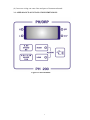
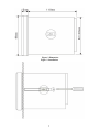
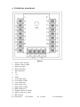
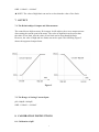
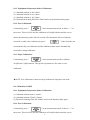
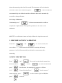
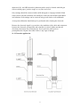
Proprietary Material
The information and descriptions contained herein are the property of ANJUN. Such
information and descriptions may not be copied or reproduced by any means, or
disseminated or distributed without the express prior written permission of ANJUN.
Statement of Limited Warranty
ANJUN warrants equipment of its manufacture, and bearing its identification to be
free from defects in workmanship and material for a period of 36 months for
electronics and 6 months for mechanical parts and electrodes from date of delivery
from the factory or authorized distributor under normal use and otherwise when such
equipment is used in accordance with instructions furnished by ANJUN and for the
purposes disclosed in writing at the time of purchase, if any. ANJUN's liability under
this warranty shall be limited to replacement or repair, F.O.B SHANGHAI, CHINA of
any defective equipment or part which, having been returned to ANJUN,
transportation charges prepaid, has been inspected and determined by ANJUN to be
defective. Replaceable elastomeric parts and glass components are expendable and are
not covered by any warranty.
THIS WARRANTY IS IN LIEU OF ANY OTHER WARRANTY, EITHER
EXPRESS OR IMPLIED, AS TO DESCRIPTION, QUALITY, AND
MERCHANTABILITY, FITNESS FOR ANY ARTICULAI PURPOSE OR USE, OR
ANY OTHER MATTER.
TABLE OF CONTENTS
1. INTRODUCTION.............................................................................................2
2. FEATURES & SPECIFICATIONS...................................................................2
2.1. Features...........................................................................................................2
2.2. Specifications..................................................................................................2
3. INSTALLATION...............................................................................................2
3.1. Appearance & Installation Dimensions..........................................................3
4. TERMINAL DIAGRAM...................................................................................5
5. FRONT PANEL.................................................................................................6
6. ALARM SETTINGS OF HIGH AND LOW LIMITS.......................................6
7. OUTPUT.............................................................................................................7
7.1. The Relationship of Output and Measurement................................................7
7.2. The Range of Setting Current Span.................................................................7
8. CALIBRATION INSTRUCTIONS...................................................................7
8.1. Calibration of pH.............................................................................................7
8.1.1. Equipment Preparation before Calibration...................................................8
8.1.2. Zero Calibration...........................................................................................8
8.1.3. Slope Calibration..........................................................................................8
8.2. Calibration of ORP..........................................................................................8
8.2.1. Equipment Preparation before Calibration...................................................8
8.2.2. Zero Calibration............................................................................................8
8.2.3. Slope Calibration...........................................................................................9
9. RESTORE FACTORY CALIBRATION.............................................................9
10. MENU DESCRIPTION.....................................................................................9
10.1. Sensor Selection..............................................................................................9
10.2. High Limit of Current....................................................................................10
10.3. Low Limit of Current.....................................................................................10
10.4. Calibration Setting of Temperature................................................................10
10.5. Exit Menu.......................................................................................................10
11. MAINTENANCE AND APPLICATION OF ELECTRODE...........................10
11.1. Electrode Maintenance...................................................................................10
11.2. Electrode Application......................................................................................11
1
1. INTRODUCTION
The ANJUN PH200 Series pH/ORP Controller can be applied to Petrochemical, Oil
Refining, Metallurgy, Machinery, Power Plants, Paper, Pharmaceutical, Printing and
Dyeing, Food, Fermentation and Environment Protection Industries for continuous
monitoring of pH/OPR of industrial processes.
2. FEATURES & SPECIFICATIONS
2.1. FEATURES
•High anti-interference ability.
•The distance from pH/ORP controller to electrode is up to 100m.
•Isolated output :4~20mA.
•LCD display with back light.
•High and low limits alarm.
•The solution can automatic compensate the temperature which is from 0 to 100℃.
2.2. SPECIFICATIONS
• Display: LCD display with back light.
• Measuring Range:
pH:0.00~14.00pH; ORP:-1999~+1999mV
• Output:4~20mA
• Ambient Temperature:-10~+60℃; Relative Humidity:0~95%, Non-condensing
• Storage Environment:-20~+70℃; Relative Humidity:0~95%, Non-condensing
• Relay:Two relays; SPDT contact; 3A 110/220V, 3@30VDC impedance
• Temperature Compensation:PT1000RTD, 0~100℃
• Accuracy:0.25%
• Stability:0.1% per 24 hours, No cumulative
• Repeatability:0.1%
• Power Supply:90~130VAC, 50/60HZ (MAX 10VA) or 180~260VAC, 50/60HZ
(MAX 10VA)
• Dimensions:96×96×125mm
• Weight:About 1kg
3. INSTALLATION
The instrument is installed on the switchboard and gripped both sides with attached
clips, then tighten the bolts.
★ NOTE:The following steps should be confirmed before wiring.
(1) If the power supply is matched with the instrument, 220VAC or 110VAC.
(2) The power is cut off.
(3) It is best that the power is three wires, one of which is the ground wire.
2
(4) Incorrect wiring can cause lines and parts of instrument burned.
3.1. APPEARANCE & INSTALLATION DIMENSIONS
Figure 1 Panel Mounted
3
Figure 2 Dimension
Figure 3 Installation
4
4. TERMINAL DIAGRAM
Figure 4
1. Positive Pole of Input
2. Negative Pole of Input
3. Input of PT1000
4. Input of PT1000
5. No Connection
6. -5V
7. +5V
8. GND
9. Low Alarm (NO)
10. Low Alarm (COM)
11. Low Alarm (NC)
12. High Alarm (NO)
13. High Alarm (COM)
14. High Alarm (NC)
15. Negative Pole of 4~20mA
16. Positive Pole of 4~20mA
17. BNC Socket
P1: Neutral (N)
P2: 220VAC
P3: 110VAC
5
P4: Ground (G)
5. FRONT PANEL
1. LCD display, it can show measurements, alarm settings and calibrate settings.
2. "pH" or "mV" are the measuring tip lights, which flash when pH/ORP is ok.
3. "H" is the alarm light of high limit, which flashes when the value of pH/ORP
exceeds the high limit.
4. "L" is the alarm light of low limit, which flashes when the value of pH/ORP below
the low limit.
5. "
" : Set up "High" alarm parameter.
6. "
" : Set up "Low" alarm parameter.
7. "
" : Calibration of 6.86pH or 86mV.
8. "
" : Calibration of 4.01pH & 9.18pH or 256mV.
9. "
" : Mode switch button.
6. HIGH & LOW ALARM SETTINGS
Press "
“into the high alarm setting, the running light is off and
the high alarm setting light is on. Then press "
“to change the
high alarm parameters, the parameters can be changed quickly when
Continuously pressed. Press "
“again into the low alarm
Setting, the running light is off and the low alarm setting light is on. Then press
"
" to change the low alarm parameters, the parameters can
be changed quickly when continuously pressed.
Setting range of alarm parameters:
pH: 0.00pH ~ 14.00pH
6
ORP: -1999mV~+1999mV
★ NOTE: The value of high limit can not be set less than the value of low limit.
7. OUTPUT
7.1. The Relationship of Output and Measurement
The controller use high accuracy D/A output. It will achieve the reverse output current
after setting the current span in the menu. The value of high limit can be more than
the value of low limit, also the value of low limit can be more than high limit.
However, the value of high and low limits can not be equal. The following Figure 5
shows the supported output forms.
Figure 5
7.2. The Range of Setting Current Span:
pH: 0.00pH~14.00pH
ORP: -1999mV~+1999mV
8. CALIBRATION INSTRUCTIONS
8.1. Calibration of pH
7
8.1.1. Equipment Preparation before Calibration:
(1)
(2)
(3)
(4)
Standard solution (6.86) 100mL.
Standard solution (4.01) 100ml.
Standard solution (9.18) 100ml.
Demonized cleaning fluid 300~500mL and several absorbent filter paper.
8.1.2. Zero Calibration:
Continuously press "
" in the measurement mode, it shows "---" in
the screen. Then it will be into the calibration of 6.86pH solution and the screen
shows the measuring value after 20 seconds. The instrument will exit when the
electrode is stable. Also continuously press "
" if the electrode can
not automatically exit calibration and the calibration data can be automatically
saved after exiting calibration.
8.1.3. Slope Calibration:
Continuously press "
" in the measurement mode to calibrate
4.01pH and 9.18pH solution. The specific operations are the same as zero
calibration.
★NOTE: Zero calibration is must and only calibrate the slope does not work.
8.2. Calibration of ORP
8.2.1. Equipment Preparation before Calibration:
(1) Standard solution (86mV) 100mL.
(2) Standard solution (256mV) 100mL
(3) Deionized cleaning fluid 300~500mL and several absorbent filter paper.
8.2.2. Zero Calibration:
Continuously press "
" in the measurement mode, it shows "---" in
the screen. Then it will be into the calibration of 6.86pH solution and the screen
8
shows the measuring value after 20 seconds. The instrument will exit when the
electrode is stable. Also continuously press "
" if the electrode can
not automatically exit calibration and the calibration data can be automatically
saved after exiting calibration.
8.2.3. Slope Calibration:
Continuously press "
" in the measurement mode to calibrate
4.01pH and 9.18pH solution. The specific operations are the same as zero
calibration.
★NOTE: Zero calibration is must and only calibrate the slope does not work.
9. RESTORE FACTORY CALIBRATION
Press both "
" and "
" for several seconds, the
screen shows "---" , which means the instrument is restoring the factory
parameters. And it will automatically switch back to measurement after
recovering.
10.MENU DESCRIPTION
Press "
" and "
the screen shows "
" for several seconds into the menu when
". Press "
" to look at the menu and
press "
" into the menu, the meanings for menu are as follows:
10.1. "
" Sensor Selection:Press "
sensor selection, press "
press "
" into the menu of
" to select sensor of pH or ORP, then
" to save it.
9
10.2. "
" High Limit of Current:20mA corresponding measured
values, press "
10.3. "
press "
10.4. "
" to change and save automatically.
" Low Limit of Current:4mA corresponding measured values,
" to change and save automatically.
" Calibration Setting of Temperature:Don't change it, or it
may affect the accuracy of measurement.
10.5. "
" Exit Menu:Press "
" to exit menu and return to
state of measurement.
11. MAINTENANCE AND APPLICATION OF ELECTRODE
The PH200 control module itself needs very little maintenance. Clean the outside of
the controller enclosure with a damp cloth. Do not spray down the controller unless
the enclosure door is closed and latched. "Pigtails" should be protected from spray or
wash-down. Check the cords and cables for damage.
11.1. Electrode Maintenance
The pH or ORP electrodes require periodic cleaning and calibration. These electrodes
are like batteries and their voltage outputs will change with time even if they are not
being used. After installation, the rate of change increases, and factors such as
temperature, extremes of pH, abrasion and chemical attack will increase the required
frequency of calibration. If the process solution contains oils, scale or other solids, the
electrode surface will tend to coat, its response time will slow down and cleaning will
be required.
The frequency of cleaning and calibrating will vary greatly depending upon the
application, the factors listed above, as well as the accuracy of control you require.
The best way to determine the optimum number of days between calibrations is to
remove the electrode from the process periodically (weekly in clean water
applications, daily in dirty or hot applications) and check its accuracy in a buffer
solution. If using manual temperature compensation, remember to change the
temperature from that of the process to that of the buffer. If the accuracy of the
reading is within your required tolerances, and the speed of response is good, replace
the electrode in the process. If not, clean the electrode and perform a two point
calibration.
The method of cleaning the electrode will depend upon the coating, as well as the
materials of construction of the electrode. Do not use a solvent that will attack the
electrode! Care must be taken to avoid scratching the pH electrode's glass, as this will
10
shorten its life. An ORP electrode's platinum surface may be cleaned with 600 grit
silicon carbide paper, jewelers rouge or very fine steel wool.
Oily coatings should be removed with a mild detergent or isopropyl alcohol. Hard
scales such as calcium carbonate can usually be removed with a dilute hydrochloric
acid solution. Soft coatings can be removed using a soft cloth or soft toothbrush.
A two point calibration should always be performed after cleaning the electrode.
Because the electrode signal is so sensitive, the condition of the cable and connectors
between the electrode, preamplifier and controller is critical. Make sure that all
electrical connections stay clean and dry. Never splice the cable prior to
preamplification. Replace the cable if there is any sign of damage.
11.2. Electrode Application
11