1
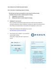
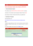
Available online at www.pelagiaresearchlibrary.com
Pelagia Research Library
Der Pharmacia Sinica, 2015, 6(5):75-80
ISSN: 0976-8688
CODEN (USA): PSHIBD
Laboratory practice of high performance liquid chromatography (HPLC)
Ufere Emele N. and Ajanwobu O. Innocent
Department of Pharmaceutical and Medicinal Chemistry, Faculty of Pharmaceutical Sciences, Nnamdi Azikiwe
University, Awka
_____________________________________________________________________________________________
ABSTRACT
This compilation is intended to guide for efficient and smooth operation of HPLC system, especially those that are
problems free. Its primary aims are to maximize system operation time and to promote good chromatographic
practices. It has also been extended to cover some aspect of troubleshooting. Wherever possible, diagrams or
schematics are used for clarity. This enables the guide to be used quickly and efficiently by operators with varying
experience. Correct solvent preparation is very important. It can save vast amounts of time spend troubleshooting
spurious peaks, baseline noise, etc…
_____________________________________________________________________________________________
INTRODUCTION
High-performance liquid chromatography (HPLC) is a form of liquid chromatography to separate compounds that
are dissolved in solution. HPLC instruments consist of a reservoir of mobile phase, a pump, an injector, a separation
column, and a detector. Compounds are separated by injecting a plug of the sample mixture onto the column. The
different components in the mixture pass through the column at different rates due to differences in their partitioning
behavior between the mobile liquid phase and the stationary phase.
All reagents and solvents should be of the highest quality. HPLC grade reagents may cost slightly more than lower
grade reagents, but the difference in purity is marked. HPLC grade reagents contain no impurities to produce
spurious peaks in a chromatogram baseline. Water used in buffer preparation is of highest purity, demonized water
often contains trace levels of organic compounds, therefore, is not recommended for HPLC use. Ultra pure HPLC
water (18M_ resistivity) is generated by passing demonized water through an ion exchange bed. Modern water
purification instruments use this mechanism to produce water of suitable quality in high volumes. Alternately,
HPLC grade water can be purchased from solvent suppliers..1 Quality
All buffers should be prepared freshly on the day required. This practice ensures that the buffer pH is unaffected by
prolonged storage and that there is no microbial growth present. Changes in pH and microbial growth will affect
chromatography.
If buffer solutions are stored, be aware that they have a finite lifetime. This can be found in pharmacopeia or
monographs on buffer shelf life.
Buffer reagents can contain a stabilizing agent (chemicals that inhibit reaction of other chemicals), eg. Sodium
metabisulphite. These stabilizing agents often affect the optical and chromatographic behaviour of buffer solutions,
so it is worth buying reagents that contain no stabilizer. Containers of solid reagent are easily contaminated by
repeated use. For this reason, we recommend that regents be purchased in low container weights.
75
Pelagia Research Library
Ufere Emele N. and Ajanwobu O. Innocent
Der Pharmacia Sinica, 2015, 6(5):75-80
_____________________________________________________________________________
MATERIALS AND METHODS
2.1 Mobile Phase Properties
Do not use highly acidic or basic solvents unless your HPLC system and column have been engineered to
accommodate them. Seals, plungers etc. can be damaged by extreme pH conditions. If in doubt, please contact your
column or instrument supplier before using an aggressive solvent.
The use of highly aqueous mobile phases is becoming more popular as safety guidelines demand less exposure to
organic solvents. Care should again be taken that the HPLC column has been engineered to accommodate highly
aqueous solvents. Highly aqueous mobile phases are ideal breeding grounds for microbes. Ensure that an organic
solvent is flushed through the HPLC system and column at least once every 48 hours to kill unwanted microbial
growth.
2.2 Solvent Use4.2.1 Instrument
Each solvent line should be fitted with an inlet filter. This is the first line of system defense against particulate
contamination from solvents. The filters should be kept clean to prevent cross contamination.
When they are not being used, it is recommended that they are stored in a solution of 50% acetonitrile/50% water.
This will inhibit microbial growth and stop dust and dirt from embedding in the filter pores.
The solvent lines should be clean, growth-free and should have no sharp bends or creases in them. Solvent reservoirs
should be placed as high as possible on or in the instrument – always higher than the pump inlet manifold. The
solvent lines and filters should be of sufficient length to reach the bottom of the solvent reservoir.
Note: Before starting an analysis, calculate the total volume of mobile phase required.
Prepare all the phases at the same time and place in reservoirs that are large enough to accommodate them.
Insufficient mobile phase may cause the system to pump dry. This is undesirable because it will fill the system with
air. If this does happen, purge the solvent lines and pump with fresh solvent then allow the system to pump solvent
until it is equilibrated.
2.3 Changing Solvents1 Buffered Phase to Wash or S
Ensure that the buffer is soluble in the proposed wash or storage phase. If it is not, first flush the system with a
solvent mix that is highly aqueous to remove the buffer from the system and column, and then change to the
proposed wash or storage solvent mixed.
There are few occasions where these solvent changes will be necessary. Such occasions include columns that can be
used with both solvent types or systems where both normal and reversed phase analyses are performed. Where
possible, systems should be dedicated to normal or reversed phase chromatography.
To convert a normal phase system/column to a reversed phase system/column, flush with a solvent that is miscible
with both the current normal phase solvents and ideally, the proposed reversed phase solvents. If the final reversed
phase solvents include a buffer, then it is advisable to move from the 100% methanol flush to a 50% aqueous
methanol flush. For example,
Normal Phase Hexane/Ethyl Acetate
Flush IPA then Methanol
Finally 50:50 Methanol/Water
Reversed Phase Buffered Aqueous Methanol
Flush 50:50 Methanol/Water
Normal Phase Hexane/Ethyl Acetate
2.4 Filtration
Ideally, all HPLC solvents should be filtered through a 0.45 µm filter before use. This removes any particulate
matter that may cause blockages. After filtration, the solvents should be stored in a covered reservoir to prevent
contamination with dust etc. Filtering HPLC solvents will benefit both your chromatography and the wear and tear
of the HPLC system. Pump plungers, seals and check valves will perform better and lifetimes will be maximized.
76
Pelagia Research Library
Ufere Emele N. and Ajanwobu O. Innocent
Der Pharmacia Sinica, 2015, 6(5):75-80
_____________________________________________________________________________
2.5 Degassing
Before the freshly prepared mobile phase is pumped around the HPLC system, it should be thoroughly degassed to
remove all dissolved gasses. Three methods of degassing are listed below;
• Bubbling with helium
• Sonication
• Vacuum filtration
If the mobile phase is not degassed, air bubbles can form in the high-pressure system resulting in problems with
system instability, spurious baseline peaks etc.
Fig 2.1 Degassed and non Degassed mobile phase
The most efficient form of degassing is bubbling with helium or another low solubility gas. If this method is
available, I recommend that the mobile phase is continually degassed at very low levels throughout the analysis.
This will inhibit the re-adsorption of gases over the analysis time.
2.6 Column Cleaning
In all instances, the volume of solvent used is 40-60 column volumes unless otherwise stated.
Ensure that no buffers/samples are present on the column and that the solvent used prior to the clean-up is miscible
with the first wash solvent.
After the clean-up, ensure that the test mobile phase is compatible with the last solvent in the column.
2.5.1 Normal phase media
1. Flush with tetra hydro furan
2. Flush with methanol
3. Flush with methylene chloride
4. Flush with benzene-free n-hexane
2.5.2 Reversed phase media
1. Flush with HPLC grade water; inject 200 µL DMSO during this flush
2. Flush with methanol
3. Flush with chloroform
4. Flush with methanol
2.6.3 Anion exchange media
1. Flush with HPLC grade water
2. Flush with methanol
3. Flush with chloroform
2.5.4 Cation exchange media
1. Flush with HPLC grade water; inject 200 µL DMSO during this flush
77
Pelagia Research Library
Ufere Emele N. and Ajanwobu O. Innocent
Der Pharmacia Sinica, 2015, 6(5):75-80
_____________________________________________________________________________
2. Flush with tetrahydrofuran
2.5.5 Protein size exclusion media
There are two wash/regeneration procedures associated with the removal of contaminants from protein size
exclusion media.
Weakly retained proteins
Flush with 30 mL, 0.1M, pH = 3 phosphate buffer
Strongly retained proteins
Flush for 60 minutes using 100% water to 100% acetonitrile gradient.
2.5.6 Porous graphitic carbon
There are four wash or regeneration procedures associated with porous graphitic carbon. The one(s) used will
depend on the analytes and solvents that have been used with the column.
2.5.7 Acid/Base Cleaning
Suitable for ionized species analyzed in strongly aqueous mobile phases.
1. Invert the column
2. Flush at 1 mL/min with 50 mL tetrahydrofuran/water (1:1) containing 0.1% trifluoroacetic acid.
3. Flush at 1 mL/min with 50 mL tetrahydrofuran/water (1:1) containing 0.1% triethylamine or sodium hydroxide
4. Flush at 1 mL/min with 50 mL tetrahydrofuran/water (1:1) containing 0.1% trifluoroacetic acid
5. Flush with methanol/water (95:5) to re-equilibrate
6. Re-invert the column
2.5.8 Strong Organic Cleaning
Suitable for applications involving polar and/or ionized species analyzed in aqueous mobile phases.
1. Flush at 1 mL/min with 50 mL acetone
2. Flush at 1 mL/min with 120 mL dibutylether
3. Flush at 1 mL/min with 50 mL acetone
4. Flush with aqueous mobile phase until equilibrated
2.5.9 Normal Phase Cleaning
Suitable for applications running predominantly in normal phase mobile phases.
1. Flush at 1 mL/min with 50 mL dichloromethane
2. Flush at 1 mL/min with 50 mL methanol
3. Flush at 1 mL/min with 50 mL water
4. Flush at 1 mL/min with 50 mL 0.1 M hydrochloric acid
5. Flush at 1 mL/min with 50 mL water
6. Flush at 1 mL/min with 50 mL methanol
7. Flush at 1 mL/min with 50 mL dichloromethane
8. Flush with mobile phase until equilibrated
2.5.10 Removal of Trifluoroacetic acid
Suitable for applications running mobile phases containing trifluoroacetic acid.
Flush the column with acetonitrile that has been heated to 75°C. the column should also be maintained at this
temperature.
2.6 System plumbing and fittings
The purpose of a well-plumbed HPLC system is to minimize dead volume between its components and to eliminate
leaks. System tubing errors show themselves in many ways, for example as band broadening, baseline noise, etc…
detection of incorrect diameter tubing is often very difficult. The internal diameter of tubing used in a HPLC system
varies with the position in the instrument; refer to your system maintenance manuals.
The type of tubing used is determined by the application that is being performed. The two most common types of
tubing are steel and PEEKTM, although others are also available, when changing tubing, make sure that the
replacement is manufactured from a material that is compatible with any solvents that may be flushed through it.
78
Pelagia Research Library
Ufere Emele N. and Ajanwobu O. Innocent
Der Pharmacia Sinica, 2015, 6(5):75-80
_____________________________________________________________________________
2.7 Cutting tubing
Tubing should always be cut using instruments that are designed for the purpose. The use of scissors and wire
cutters is not recommended as they can deform the tubing bore and almost always produce angled cuts that are one
of the biggest causes of leaks and increased dead volume.
Note: Where possible, pre-cut tubing should always be used.
2.7.1 Stainless Steel
Stainless steel can be effectively cut using the procedure outlined below:
1. Estimate the length required. Remember to allow extra length if the tubing is to go around corners as sharp bends
in the tubing will distort the inside bore and hence the solvent flow through it.
2. Using a stainless steel cutter, score cleanly round the tubing. If a cutter is unavailable, use a knife-file to score
the tubing. Care should be taken, whichever method is used, not to distort or damage the tubing.
3. Using two pairs of smooth jawed pliers, one above the score and one below it, gently bend the tubing back and
forth until it snaps. Excessive bending should be avoided as this will damage the tubing and not give a clean break.
4. There will be one or two burrs present on the cut surface. These can be carefully filed away to give a smooth, flat
cut surface. Care should be taken not to allow any filed material to block the tubing bore.
2.7.2 PEEK or Polymeric Tubing
The simplest way to cut polymeric tubing is using a blade, for example a razor blade or craft knife. The polymeric
tubing cutters that are supplied by many manufacturers are essentially a razor blade in safety housing. The
advantage of using one of these cutters is that they hold the tubing at 90° to the blade so a clean, flat cut is assured.
Polymeric tubing can be effectively cut using the procedure outlined below:
1. Estimate the length required. Remember to allow extra length if the tubing is to go around corners as sharp bends
in the tubing will distort the inside bore and hence the solvent flow through it.
2. Use a sharp blade or specialist cutter to cut the tubing. Do not use a “sawing” action. This will give an uneven
cut surface. Make the cut in a single action.
3. Inspect the cut surface for burrs. These can be carefully filed away to give a smooth, flat cut surface. Care should
be taken not to allow any filed material to block the tubing bore.
As a final action, after cutting the tubing and before connecting it to the HPLC, flush it with solvent to remove any
filed material, dust or other debris that could be in the tubing bore. The tubing is now ready to have fittings attached
to it.
2.7 Fittings
Fittings are available in stainless steel and a range of polymeric compounds. In general, you should use stainless
steel fittings with stainless steel tubing, PEEK fittings with PEEK tubing etc.
I recommend that compression fittings and ferrules from different manufacturers are never interchanged. The
dimensions of the fitting and ferrule vary between suppliers, so mixing them often leads to leaks, stripped threads
and damage to female ports such as column inlet and outlets, detector inlets etc.
The amount of tubing that extends past the ferrule also varies with manufacturer. If the tubing does not seat properly
within the female fitting, then leaks and increases in dead volume will occur.
Laboratories that contain instruments from more than one manufacturer often find it useful to purchase “universal”
fittings. These fittings are compatible with all instruments.
RESULTS
3.1 Band spreading or Band broadening
Broad peaks, often accompanied by a change in retention time, indicate band spreading. It can occur within the
HPLC column, but is more often due to incorrect system plumbing. The following procedure describes a method for
measuring band spreading due to the HPLC system. Column effects can be measured using efficiency calculations.
1. Remove the HPLC column from the system and replace with a zero dead volume union.
2. Configure the HPLC system with the following parameters:
Flow rate: 1 mL/min Detector sensitivity: 0.5 to 1.0 AUFS
Detector time constant: 0.2 or less Chart speed (if required): 20 cm/min
79
Pelagia Research Library
Ufere Emele N. and Ajanwobu O. Innocent
Der Pharmacia Sinica, 2015, 6(5):75-80
_____________________________________________________________________________
3. Perform a ten-fold dilution of the column efficiency test solution. Inject 5 µL of this diluted mix.
4. Adjust the detector sensitivity until the peak height is approximately 75% of the full-scale readout.
5. Measure the peak width at 4.4% peak height (5-sigma column efficiency method).
6. Convert the peak width to mL using the following conversion:
Band spread (µL) = peak width x (1/20) x 1 x 1000
Where peak width is measured at 4.4% peak height and expressed in cm; (1/20) represents the chart speed, min/cm;
1 represents the flow rate, mL/min and 1000 represents the volume correction factor, µL/min.
RFERENCES
[1] Jerry Demenna, workshop in spectroscopy and chromatography, Buck Scientific Incorporated, USA, pp 9, 27,
127,
[2] Gurdeep R. Chatwal, Instrumental methods of chemical analysis 5th ed. Mumbai, Himalaya publishing house
2002, pp 2.566-2.568-2.640
[3] Chmwiki. eucdavis.edu@api/deki/pages/2928/pdf
[4] www.fda.gov/ucm
[5] www.hplctraining.blogspot.com
[6] User manual for Liquid chromatography, buck scientific incorporated, BLC Series, pp.172-186,
[7] http://www.kobisi.si/material/HPLCTroubleshooting.pdf
[8] www.kobis.s/material/hplctroubleshooting
[9]http://www.knauer.net/fileadmin/user_upload/product/files/document/applica
tion_notes.si/material/HPLC_troubleshooting_guide.pdf
[10] www.sigma-aldrich.com
[11] http://www.pharmatutor.org
[12] www.unine.ch/files/content/sites/s
80
Pelagia Research Library